An Introduction to ASM86 - Internet Archive
111
I® AN INTRODUCTION I Order Number: 121689-001
Transcript of An Introduction to ASM86 - Internet Archive

I®
ANINTRODUCTION
I
Order Number: 121689-001

Order Number: 121689-001
Copyright % 1981 Intel Corporation
Intel Corporation, 3065 Bowers Avenue, Santa Clara, California 95051

Additional copies of this manual or other Intel literature may be obtained from:
Literature Department
Intel Corporation
3065 Bowers AvenueSanta Clara, CA 95051
The information in this document is subject to change without notice.
Intel Corporation makes no warranty of any kind with regard to this material, including, but not limited
to, the implied warranties of merchantability and fitness for a particular purpose. Intel Corporation
assumes no responsibility for any errors that may appear in this document. Intel Corporation makes no
commitment to update nor to keep current the information contained in this document.
Intel Corporation assumes no responsibility for the use of any circuitry other than circuitry embodied in
an Intel product. No other circuit patent licenses are implied.
Intel software products are copyrighted by and shall remain the property of Intel Corporation. Use,
duplication or disclosure is subject to restrictions stated in Intel's software license, or as defined in ASPR7-104. 9(a)(9).
No part of this document may be copied or reproduced in any form or by any means without the prior
written consent of Intel Corporation.
The following are trademarks of Intel Corporation and its affiliates and may be used only to identify Intel
products:
BXPCREDIT
Intel Library Manager
MCSMegachassis
Micromainframe
Micromap
Multibus
Multimodule
Plug-A-Bubble
ICEiCS
im
Inlellec
iRMXiSBC
iSBX
Intelevision
PROMPTPromware
RMX/80System 2000
UPlInsite
and the combination of ICE, iCS, iRMX, iSBC, iSBX, MCS, or RMX and a numerical suffix.

REV. REVISION HISTORY DATE
-001 Original issue. 9/81

Digitized by the Internet Archive
in 2014
https://archive.org/details/introductiontoasOOinte

PREFACE
This manual iS an introduction to ASM86. Intel's 8086/8088 assembly language. It is designed to
teach you the fundamentals of constructing an ASM86 source module, and to provide the
conceptual background you will need in order to write ASM86 code. To aid your understanding,
a number of drawings, examples, and syntax diagrams are presented along with the text.
Occasionally, generality is sacrificed in favor of simplicity, so that the most important points
can be brought to your attention. Refer to the related publications listed below, particularly the
ASM86 Language Reference Manual . for details and additional information to supplement the
material in this manual.
MOV AX.BX
Does the above line make sense to you? It should. This manual is written for programmers whohave some knowledge of the 8086/8088 architecture, and some familiarity with assembly
language. It is assumed that you will recognize, for instance, that MOV is an 8086/8088
instruction, that AX and BX are registers, and that the line MOV AX.BX is an assembly
language instruction statement. Although this is an introductory manual, describing the
8086/8088 architecture and explaining the principles of coding in assembly language are con-
sidered to be outside the scope of this manual.
This manual contains seven chapters and an appendix, which are briefly described below:
• Chapter 1 , "Overview of the 8086/8088 Assembly Language." describes the elements that
make up an ASM86 source module and then explains a few of the features of the assembly
language.
• Chapter 2, "Segmentation," explains the segmented memory structure presented by the
8086 and 8088 miicroprocessors and how this is reflected in the assembly language,
• Chapter 3, "Data," describes the ASM86 constructs used to allocate and access the data
portion of your assembly language program.
• Chapter 4. "Modular Programming." explains how programs may be divided into several
source modules and how procedures are defined and called in ASM86 modules.
• Chapter 5. "Combining ASM86 and PL/M-86 Modules." describes hov./ assembly
language modules may be used together with modules written in PL/M-86 'a high-level
language) to construct a program. Although PL/M is discussed throughout this chapter,
much of the material will be valuable even to programmers who will not be writing PL'Mcode.
• Chapter 6. "Helpful Hints," is a brief chapter which takes up some sidelights, useful
programming ideas, that were purposely avoided in the chapters presenting core
material.
• Chapter 7, "What's Next?," is a preview of coming attractions. This chapter briefly
summarizes some of the areas not covered in this manual, but described in other ASM86documentation.
• Appendix A. "Source Module Templates." shows the assembly language statements that
make up the framework of ASM86 modules designed to be used with PL/M-86.

RELATED PUBLICATIONS
For further, more detailed information about Intel's 8086/8088 assembly language and ASM86assembler, see the following manuals:
• ASM86 Language Reference Manual, ^2^703
• 8086/8087/8088 Macro Assembler Operating Instructions for 8086-Based Development
Systems. 121628
or
• 8086/8087/8088 Macro Assembler Operating Instructions for 8080/8085-Based
Development Systems , 121624
or
• MCS-86 Macro Assembler Operating Instructions for ISIS-II Users , 9800641
For a description of the 8086/8088 architecture and an overview of the ASM86 and PL/M-86
languages, see:
• Morse, Stephen P., The 8086 Primer, Hayden Book Company, Inc., Rochelle Park. NewJersey, 1980.
For information on the 8086 and 8088 microprocessors and the 8087 Numeric Data Processor,
see:
• The 8086 Family User 's Manual , 9800722
• The 8086 Family User's Manual, Numerics Supplement, 121586
For information on the PL/M-86 programming language and compiler, see:
• PL/M-86 User's Guide for 8086-Based Systems, 121636
or
• PL/M-86 Programming Manual, 9800466
• PL/M-86 Compiler Operating Instructions for 8080/8085-Based Development Systems,
9800478
For information on the LINK86 and LOC86 utility programs, see:
• iAPX 86, 88 Family Utilities User 's Guide ,121616
or
• 8086 Family Utilities User's Guide , 9800639
NOTATIONAL CONVENTIONS
UPPERCASE Assembler keywords and program symbols are shown in uppercase to
distinguish them from other text. In syntax diagrams, characters shown in
uppercase must be entered exactly as shown.
Examples:
MOV, EQU, VAR_1

italics Italics are used in syntax diagrams to indicate variable information.
Italicized words are placeholders for other symbols to be substituted into
a statement.
Examples:
[ ]
{ }
symbol-name, expression
Brackets indicate optional arguments or fields within an assembly
language statement. When a list of items, separated by vertical bars, is
enclosed in brackets, then only one of the items may optionally be
specified.
Examples:
[var-name], [ NEAR |FAR
]
Brackets followed by ellipses indicate that the enclosed arguments or
fields may occur zero or more times. In particular, the construct item[ ,
item ]... is used to indicate that one item is required, and others mayoptionally follow in a list, where items are separated by commas.
Example:
segname[ ,segname ]...
Braces indicate that one and only one of the enclosed items must be
selected. Options are stacked inside the braces.
Example:
special
symbols
Vertical dots indicate that some assembly language statements have
been omitted to emphasize the statements shown.
Example:
NAME EXAMPLE 1
BVAR DB 0
Special symbols ('$&?;:=,[]. + -()*/<>) and spaces shown in ASM86statements are required by the assembly language and must be entered
as shown.
Examples:
MOV AX.BXPACK: MOV AX, WORD PTR
DW 1,2 DUP (3 DUP (0)
,
BYTE WIDE NUMBER DB ? ;
ES:UNPACKED_NUMBER[SI]4)
indeterminate initialization
VII


CONTENTS
Page
CHAPTER 1: OVERVIEW OF THE 8086/8088 ASSEMBLY LANGUAGEWhatlsASM86? 1
Elements of the 8086/8088 Assembly Language 1
Operand Typing and Code Generation 3
Registers 3
Variables 3
Labels 4
Constants 4
Generating Opcodes from General Purpose Mnemonics 4
Convenience Features 5
Equates 5
Forward References 6
Example Code 7
Chapter Summary 8
CHAPTER 2: SEGMENTATIONThe Concept of Segmentation 9
The Parts of a Program: Code, Data, and Stack 9
Addressing from a Base Location 10
Addressing on the 8086/8088 11
The 8086/8088 Segmented Architecture 13
Base Locations and Physical Addresses 13
The ASM86 Programmer's View of Segmentation 14
Another Kind of Segment 14
The SEGMENT and ENDS Statements 14
Setting Up the Segment Registers 15
Changing Segment Register Values 17
The ASSUME Statement 18
Example Program 19
Chapter Summary 22
CHAPTERS: DATAData Allocation 25
Defining Variables 26
Referencing Variables 27
Addressing Modes 27
Direct Offset Addressing 27
Indirect Addressing 28
Register-Offset Addressing 29

CONTENTS (Cont'd.)
Page
Addressing Through Two Registers 30
Summary of Addressing Modes 30
Attribute Overrides 30
Segment Overrides 31
Type Overrides 32
Example Program 33
Chapter Summary 36
CHAPTER 4: MODULAR PROGRAMMINGProgramming v^/ith Multiple Source Modules 37
Linking Modules Together 37
The PUBLIC and EXTRN Directives 38
Combining Logical Segments 39
The Attributes of Logical Segments 40
The Combine-Type Attribute 41
The Align-Type Attribute 44
The Class-Name Attribute 44
Groups 44
Using Procedures 47
Defining Procedures: The PROC/ENDP Statements 47
Passing Parameters to Procedures 48
Returning Values from Procedures 49
Example Program 49
Chapter Summary 54
CHAPTER 5: COMBINING ASM86 AND PL/M-86 MODULESThe PL/M-86 Procedural Interface 55
The PL/M Method of Passing Parameters 55
Retrieving Parameters from the Stack 56
Choosing a Method to Access Parameters 59
Returning Values from Functions 59
Register Conventions 59
Models of Computation 60
Case Study: PL/M SMALL 60
CGROUPand DGROUP 60
Register Initialization 61
Offsets in the SMALL Model 62
The SMALL Case Procedural Interface 62
Extending the SMALL Model 62
Example Program 63
Other Models of Computation 69
The COMPACT Model 69
The MEDIUM Model 70
The LARGE Model 70
Program Templates 70
Chapter Summary 70
X

CONTENTS (Cont'd.)
PageCHAPTERS: HELPFUL HINTSAliases for Variables 73
Aliases for Parameters on the Stack 74
Long ConditionalJumps 74
Short Jumps 75
Using a Number for Direct Offset Addressing 76
Absolute Code 77
Chapter Summary 77
CHAPTER 7: WHAT'S NEXT?8086/8088 instruction Set 79
8087 Code 79
Expressions 79
Structures 80
Records 80
Macros 81
Assembler Controls 82
Chapter Summary 82
APPENDIX A: SOURCE MODULE TEMPLATESUsing the Templates 83
The PL/M-86 SMALL Model of Computation 84
Notes on the SMALL Model 85
The PL/M-86 COMPACT Model of Computation 86
Notes on the COMPACT Model 87
The PL/M-86 MEDIUM Model of Computation 88
Notes on the MEDIUM Model 89
The PL/M-86 LARGE Model of Computation 90
Notes on the LARGE Model 91
ILLUSTRATIONS
FIGURE TITLE PAGE
1-1 A Partial ASM86 Module 7
2-1 A Simple Program in Memory 9
2-2 The Code, Data, and Stack Portions of the Simple Program 10
2-3 The Address of W0RD_3 Relative to Physical Location 0 10
2-4 The Address of W0RD__3 Relative to the Data Region Base Location 11
2-5 The Address of WORD^S as an Offset from the DS Register 12
2-6 The Program Regions Associated with the CS, DS, SS, and ES Registers 12

ILLUSTRATIONS (Cont'd.)
FIGURE TITLE PAGE
2-7 Calculating the Physical Address of WORD^S 14
2-8 The Run-Time Stack 16
2-9 A Simple ASM86 Module Using the SEGMENT/ENDS and ASSUME Statements 20
2-10 The ASSUME and SEGMENT/ENDS Statements in the Example Program 21
3- 1 A Simple ASM86 Module Demonstrating Data Definition, Addressing Modes,
and Attribute Overrides 33
4-1 Uncombined Logical Segments from M0DULE_1 and M0DULE_2 39
4-2 Desired Combination of Logical Segments from M0DULE_1 and M0DULE_2 . 40
4-3 Combining the PROG_DATA Segments 42
4-4 Combining the PROG STACK Segments 43
4-5 The Three Distinct Data Regions: PROG_CONST, PROG_DATA,and PROG_STACK 45
4-6 The Data Group, Composed of Three Regions: PROG_CONST, PROG_DATA,and PROG„STACK 46
4-7 Bases and Offsets in DATA^GROUP 46
4-8 Main Module for Example Program 50
4-9 Other Module for Example Program 51
5- 1 State of the Stack Following CALL P(WVAL,BVAL,PVAL); 56
5-2 State of the Stack Inside P After PUSH BP and MOV BP,SP 58
5-3 Memory Layout fora PL/M SMALL Program 61
5-4 A Template for a SMALL Case Program 61
5-5 PL/M Main Module for Example Program 63
5-6 ASM86 Module Containing Support Procedures and Data Table Segment 64
6- 1 Long Jufnp on Zero to TARGET: Vectored-Jump Method 74
6-2 Long Jump on Zero to TARGET: Jump-Around-Jump Method 75
A-1 SMALL Model Template 84
A-2 COMPACT Model Template 86
A-3 MEDIUM Model Template 88
A-4 LARGE Model Template 90
TABLES
TABLE TITLE PAGE1-1 8086/8088 Registers 3
3-1 Addressing Modes on the 8086/8088 30
7-1 Partial List of Assembly-Time Operators 80
xii

CHAPTER 1
OVERVIEW OF THE 8086/8088ASSEMBLY LANGUAGE
This chapter introduces ASM86, Intel's 8086/8088 assembly language. It describes the makeupof an ASM86 source file and then explains a few of the features of the assembly language. Thechapter concludes with an example program fragment containing samples of commonly used,
easy-to-understand assembly language statements.
What is ASM86?
ASM86 is the name of Intel's 8086/8088 assembly language. Statements written in this
language are used to specify machine instructions for the 8086 or 8088 and to allocate memoryspace for program data. These human-readable statements are translated into a machine-
readable form by a program called the ASM86 assembler. The input to the assembler is a
source file containing assembly language statements. The assembler produces two output
files: an object file and a listing file . The object file contains the machine-readable translation
of the statements in the source file; the listing file shows this machine code in hexadecimal
form, along with the ASM86 source statements from which it was produced.
The name "ASM86" is used in a variety of ways. For example, a program written in Intel's
8086/8088 assembly language is often called an ASM86 program, and the statements in a
source file for such a program are generally referred to as ASM86 code . The assembler itself is
often called ASM86 after the language it recognizes. Keep in mind, though, that the topic of
this manual is writing ASM86 code, not operating the assembler.
ELEMENTS OF THE 8086/8088 ASSEMBLY LANGUAGE
The statements in an ASM86 source file can be classified in three general categories: instruc-
tion statements, data allocation statements, and assembler directives. An instruction state-
ment uses an easily-remembered name—a mnemonic—and possibly one or two operands to
specify a machine instruction to be generated. A data allocation statement reserves, and
optionally initializes, memory space for program data. An assembler directive is a statement
that gives special instructions to the assembler. Although directives may produce something
in the object file, they are unlike the instruction and data allocation statements in that they do
not specify the actual contents of memory.
Examples of the three types of ASM86 statements are given below. These are provided to give
you a general idea of what the different kinds of statements look like. Do not be concerned if,
at this point, you do not fully understand these example statements. One of the goals of this
manual is to make them understandable to you.
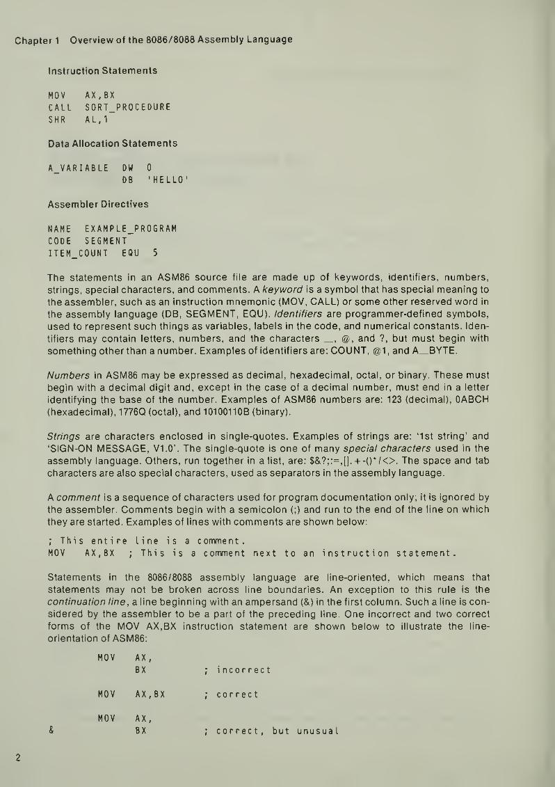
Chapter 1 Overview of the 8086/8088 Assembly Language
Instruction Statements
MOV AX.BX
CALL SORT_PROCEDURESHR AL,1
Data Allocation Statements
A_VARIABLE DW 0
DB 'HELLO'
Assembler Directives
NAME EXAMPLE_PROGRAMCODE SEGMENTITEM_COUNT EQU 5
The statements in an ASM86 source file are made up of keywords, identifiers, numbers,
strings, special characters, and comments. A keyword is a symbol that has special meaning to
the assembler, such as an instruction mnemonic (MOV, CALL) or some other reserved word in
the assembly language (DB, SEGMENT, EQU). Identifiers are programmer-defined symbols,
used to represent such things as variables, labels in the code, and numerical constants. Iden-
tifiers may contain letters, numbers, and the characters _, @, and ?, but must begin with
something other than a number. Examples of identifiers are: COUNT, @1 , and A_BYTE.
Numbers in ASM86 may be expressed as decimal, hexadecimal, octal, or binary. These must
begin with a decimal digit and, except in the case of a decimal number, must end in a letter
identifying the base of the number. Examples of ASM86 numbers are: 123 (decimal), OABCH(hexadecimal), 1776Q (octal), and 10100110B (binary).
Strings are characters enclosed in single-quotes. Examples of strings are: '1st string' and
'SIGN-ON MESSAGE, VI. 0'. The single-quote is one of many special ctiaracters used in the
assembly language. Others, run together in a list, are: $&?;:=,[]. + -()*/<>. The space and tab
characters are also special characters, used as separators in the assembly language.
A comment is a sequence of characters used for program documentation only; it is ignored by
the assembler. Comments begin with a semicolon (;) and run to the end of the line on which
they are started. Examples of lines with comments are shown below:
; This entire line is a comment.MOV AX,BX ; This is a comment next to an instruction statement.
Statements in the 8086/8088 assembly language are line-oriented, which means that
statements may not be broken across line boundaries. An exception to this rule is the
continuation line, a line beginning with an ampersand (&) in the first column. Such a line is con-
sidered by the assembler to be a part of the preceding line. One incorrect and two correct
forms of the MOV AX,BX instruction statement are shown below to illustrate the line-
orientation of ASM86:
MOV AX ,
BX incorrect
MOV AX, BX correct
MOV AX,
BX& correct. but unusual
2

An Introduction to ASM86
With two exceptions, the ASM86 source lines may be entered in a free-form fashion; that is,
without regard to the column-orientation of the symbols and special characters. One exception
was just mentioned: the ampersand used to indicate a continuation line must be placed in the
first column. The other exception is similar: a dollar-sign ($) indicating a control line must also
be placed in the first column. (Assembler controls are briefly described in Chapter 7.)
OPERANDTYPING AND CODE GENERATION
ASM86 is a strongly typed assembly language. What this means is that operands to instruc-
tions (registers, variables, labels, constants) have a type attribute associated with them which
tells the assembler something about them. For example, the operand 4 has type number,which tells the assembler that it is a numerical constant, rather than a register or an address in
the code or data. The following discussion explains the types associated with instruction
operands and how this type information is used to generate particular machine opcodes from
general purpose instruction mnemonics.
Registers
The 8086/8088 registers fit into two categories: general purpose registers and segmentregisters. The upper and lower bytes of four of the 16-bit general purpose registers are
separately addressable and may be treated as 8-bit general purpose registers. Thus, the
possible register types are: general purpose byte register (8 bits), general purpose wordregister (16 bits), and segment register (16 bits). The registers associated with each of these
types are shown below:
Table 1-1. 8086/8088 Registers
General Purpose Registers Segment Registers
Type WORD Type BYTE (Type WORD)
AX AL.AHBX BL.BHCX CL.CH CSDX DL,DH OSSI SSDl ESSPBP
Variables
A variable is a unit of program data with a symbolic name. Variables are discussed in Chapter
3. For now, we will simply note that a variable is given a type at the time it is defined, which
indicates the number of bytes associated with its symbol. Variables defined with a DB state-
ment are given type BYTE (one byte), those defined with the DW statement are given type
WORD (two bytes), and variables defined with the DD statement are given type DWORD(double-word, four bytes). The following data allocation statements are examples of BYTE,
WORD, and DWORD variable definitions:
BYTE_VAR DB 0 ; A byte variable.WORO_VAR DW 0 ; A word variable.DWORD_\/AR DD 0 ; A double-word variable.
3

Chapter 1 Overview of the 8086/8088 Assembly Language
Labels
A label is a symbol referring to a location in the program code. The simplest form of a label is
an identifier, followed by a colon (:), used to represent the location of a particular instruction.
Such a label may be on a line by itself or it may immediately precede an instruction statement
(on the same line). In the following example, LABEI 1 and LABEI 2 are both labels for the
MOV AX.BX instruction.
LABEL_1
:
LABEL_2: MOV AX.BX
Labels also have types associated with them. These types, NEAR and FAR, are discussed in
the next chapter.
Constants
A constant is a numerical value computed from an assembly-time expression. For example,
123 and 3 + 2-1 both represent constants. A constant differs from an address (a variable or
label) in that it specifies a pure number rather than a location in memory. Constants have type
number.
Generating Opcodes from General Purpose Mnemonics
Intel's 8086/8088 assembly language uses general purpose mnemonics to represent classes of
machine instructions rather than having a different mnemonic for each opcode. For example,
the MOV mnemonic is used for all of the following: move byte register to byte register, load
word register from memory, load byte register with constant, move word register to memory,
move constant to word in memory. This feature saves you from having to distinguish "move"from "load," "move immediate" from "move memory," "move byte" from "move word," etc.
Because the same general purpose mnemonic can apply to several different machine
opcodes, ASM86 uses the type information associated with an instruction's operands in deter-
mining the particular opcode to produce. For example, the instruction statement MOVVAR_1 ,123 will produce "move immediate byte to memory" (06) if the type of VAR__1 is BYTE,
and "move immediate word to memory" (07) if VAR„1 is a WORD variable.
The type information associated with instruction operands is also used to discover pro-
grammer errors, such as attempting to move a word register to a byte register, or attempting to
use a label as an operand to MOV.
The examples that follow illustrate the use of operand types in generating machine opcodesand discovering programmer errors. In each of the examples, the MOV instruction produces a
different 8086/8088 opcode, or an error. The symbols used in the examples are assumed to be
defined as follows: BVAR is a byte variable, WVAR is a word variable, and NEARLAB is a NEARlabel.
As you examine these MOV instructions, notice that, in each case, the operand on the right is
considered to be the source and the operand on the left is the destination . This is a general
rule that applies to ail two-operand instruction statements.
4

An Introduction to ASM86
MOV AX , BX
MOV DS , AX
MOV BX, DL
MOV CX,5
MOV BVAR , 1
0
MOV AL.WVARMOV NEARLAB,
5
MOV WVAR , DX
MOV BL, 1 024
(8B) Move word register to word register.(8E) Move word register to segment register.ERROR: Type conflict (word, byte).(B9) Move constant to word register.(C6) Move constant to byte in memory.ERROR: Type conflict (byte, word).ERROR: Can't use a label with MOV.
(89) Move word register to word in memory.ERROR: Constant is too large to fit in a byte
CONVENIENCE FEATURES
In addition to general purpose instruction mnemonics, ASM86 offers many more features
designed for programmer convenience. You will be introduced to many of these features as
you read through this manual. In this section, two such convenience features are discussed:
equates and forward references
.
Equates
The 8086/8088 assembly language contains a powerful equate facility, which allows you to
define symbolic names for commonly used expressions. These symbols are created with the
EQU directive, which has the following syntax:
The EQU Directive
symbol-name EQU expression
The expression field may specify a constant, an address, a register, or even an instruction
mnemonic. The symbol-name is an identifier, the name you will use to represent the
expression
.
As a simple example, suppose you are writing a program that manipulates a table containing
100 names and that you want to refer to the maximum number of names throughout the source
file. You can, of course, use the number 100 to refer to this maximum each time, as in MOVex. 100. but this approach suffers from two weaknesses. First of all, 100 can mean a lot of
things; in the absence of comments, it is not obvious that a particular use of 100 refers to the
maximum number of names. Secondly, if you extend the table to allow 200 names, you will
have to locate each 100 and change it to a 200.
Suppose, instead, that you define a symbol to represent the maximum number of names with
the following statement:
HAX_NAMES EQU 100
Now when you use the symbol MAX_NAMES instead of the number 100 (for example, MOVCX,MAX_NAMES), it will be obvious that you are referring to the maximum number of namesin the table. Also, if you decide to extend the table, you need only change the 100 in the EQUdirective to a 200 and every reference to MAX_NAMES will reflect the change.
5

Chapter 1 Overview of the 8086/8088 Assembly Language
Forward References
As another convenience feature, ASM86 allows names for a variety of program elements to be
forward referenced . This means that you may use a symbol in one statement and define it later
with another statement. As an example, you might code the following two statements:
COUNTER EQU BYTE_VARBYTE_VAR DB 0
The first line creates a new symbol, COUNTER, to be used as another name for BYTE _\/AR.
Since BYTE VAR is yet undefined, COUNTER must be remembered temporarily as a symbol
without a meaning. The next line declares BYTE VAR to be a byte variable. Using this
information, the assembler "goes back" and defines COUNTER to also be a name for this byte
variable.
Most forward references are avoidable and are introduced only to better organize the source
file. For example, reversing the order of the above lines eliminates the forward reference,
since BYTE^VAR is already defined (by BYTE__VAR DB 0) by the time COUNTER EQUBYTE^VAR is seen. There is one case, however, where a forward reference cannot be
avoided. Consider the following code fragment:
JNZ TARGET
TARGET: ADD AX, 10
In this example, a conditional jump is made to TARGET, a label farther down in the code. WhenJNZ TARGET is seen, TARGET is undefined, so this is a forward reference. Since the ADDAX, 10 instruction cannot simply be moved above the JNZ TARGET instruction, this forward
reference is unavoidable.
While forward references are necessary in cases where you jump ahead, they should general-
ly be avoided in other types of instruction statements. For example, suppose you were to code
the following two statements:
MOV VAR',
5
VAR7 DW 0
When the assembler sees a forward reference, as in MOV VAR?, 5 above, it has to guess what
the symbol is likely to represent. For instruction statements, a bad guess can lead to pro-
blems. In the above example, if the assembler had guessed that VAR? was going to be a BYTEvariable, it would not have reserved enough space for a WORD constant in the instruction. This
would produce an error message. On the other hand, if the assembler guessed that VAR? wasa WORD variable and it turned out to be a BYTE variable, then the assembler would have
reserved too much space for the instruction. In this case, no error would be reported; the
space would simply be filled with a NOP (no operation) instruction. This kind of bad guesswastes code space.
6

An Introduction to ASM86
As a general rule, it is best to restrict your forward references to assembler directives andjump ahead code, paying particular attention to avoiding them in the rest of your instruction
statements. This is easily done if you organize your source file so that the statements defining
variables and constants precede your instruction statements. Keep in mind that the fevi^er
guesses the assembler has to make, the better job it will do.
EXAMPLE CODE
The ASM86 code that follows is a program fragment, a partial source module. The vertical dots
indicate places where statements are missing. These missing statements, which are neededin order to make the source module complete, will be explained in the next chapter. For now,
let's concentrate on a few simple instruction statements, data allocation statements, and
assembler directives, shown in the program fragment below. A discussion following the codelisting explains each of the lines in the example program.
NAME EXAMPLE 1
BVAR
WVAR
HI BYTE
DB
DU
EQU
0
0
1 OH
A byte variable.A word variable.A symbol equated to a constant
MOV AL,BVARMOV AH,HI_BYTEINC AX
MOV WVAR, AX
Load byte register from byte in memoryLoad byte register with constant.Increment word register.Move word register to word in memory.
END
Figure 1-1. A Partial ASM86 Module
First, look at the comments in the code. With the exception of the first and last lines, each line
in the code contains a comment, which begins with a semicolon (;) and runs to the end of the
line. Comments are used for program documentation and can be very helpful in indicating the
programer's intent when it may not be clear from the code alone. The comments in this frag-
ment are used to indicate the function of the various assembly language statements. As such,
they are far from being typical of the comments you would find in real code.
Now, start at the top and go down through the statements in the program fragment. The first
line shows the NAME directive:
NAME EXAMPLE 1
The NAME directive gives an internal name to the object module produced by the assembler.
This module name should not be confused with a filename; it is stored inside the object file.
7

Chapter 1 Overview of the 8086/8088 Assembly Language
The next two lines are data allocation statements which define a byte variable named BVARand a word variable named WVAR:
BVAR DB 0 ;Abytevariable.WVAR OW 0 ;Awordvariable.
The define byte (DB) and define word (DW) statements are further explained in Chapter 3. Until
then, only very simple forms of these statements will be used in examples.
The line following the data allocation statements is an example of the equate directive:
HI_BYTE EQU 10H ; A symbol equated to a constant.
This statement defines a symbol named HLBYTE used to represent the hexadecimal number10H.
The next four lines are all instruction statements:
MOV AL.BVAR ; Load byte register from byte in memory.MOV AH,HI_BYTE ; Load byte register with constant.INC AX ; Increment word register.
MOV WVAR, AX ; Move word register to word in memory.
At run-time, the first instruction will move the byte variable BVAR into the AL register, the low
byte of the word-length AX register. The next instruction will load AH, the high byte of AX, with
the constant 10H (using the symbol HLBYTE). The AX register will then be incremented (INC
AX) and moved into the word variable WVAR (MOV WVAR, AX).
The last statement in the program fragment, and the last statement in any assembly language
module, is the END statement. This directive tells the assembler that it has reached the end of
the source code; no more statements will follow. (If the assembler does find text after the ENDstatement, it is flagged as an error.) The END statement may also be used to indicate the start
address for a main module (this will be shown in the next chapter).
CHAPTER SUMMARY
An ASM86 source file is made up of instruction statements, data allocation statements,
assembler directives, and comments. Instruction statements specify 8086/8088 machine codeto be generated, data allocation statements reserve space for program data, and directives
give special instructions to the assembler. Comments are used for program documentationonly; they are ignored by the assembler.
ASM86 uses general purpose mnemonics and typed operands to specify particular machine in-
structions. Programmer symbols (variables, labels, and symbols created with the EQU direc-
tive) are given a type at the time they are defined. Registers and numbers also have types. In
addition to determining particular machine opcodes to be generated, the types of operandscan also be used to discover programming errors indicated by a type conflict.
The general purpose instruction mnemonics used by ASM86 allow you to concentrate on the
function being performed, rather than forcing you to remember the name used for the par-
ticular opcode you need. For example, the instructions "move," "move immediate," "movebyte," "move word," and so on, are all specified by the mnemonic MOV in the 8086/8088
assembly language. General purpose mnemonics, equates, and forward references are
among the many convenience features designed into ASM86.
8

CHAPTER 2SEGMENTATION
The 8086 and 8088 microprocessors present a segmented view of program memory. This
chapter explains what this means and how segmentation is reflected in the assembly language
for the 8086/8088.
THE CONCEPT OF SEGMENTATION
The Parts of a Program: Code, Data, and Stack
Suppose you are designing a very simple assembly language program to be contained in a
single source file. The program you write will be a functional unit, which when assembled and
loaded will occupy one "chunk" of memory. If you had to draw a picture of this program
located in memory, you could simply sketch a band to show the extent of memory and draw
two lines across this band to show where the program starts and ends, as depicted below.
INCREASINGADDRESSES PROGRAM
Figure 2-1. A Simple Program in Memory 121689-1
The simple program you write, then, will ultimately become just a sequence of bytes in
memory, as the diagram shows. However, to you, the assembly language programmer, writing
the program is something more than merely listing a sequence of bytes. To specify machine
instructions to be executed, you use mnemonics and operands. Data is handled differently.
For example, if you need a byte of memory to hold a value, you define a variable with the DBstatement. A run-time stack, another kind of data structure used to hold return addresses and
some temporary values, also must be defined.

Chapter 2 Segmentation
As viewed by the programmer, an assembly language program is partitioned into code, data,
and stack . These conceptually different parts of the program also tend to reside in their owndistinct portions of memory, since intermixing these regions can lead to chaos: data executed
as code, a stack wiping out variables as it grows, etc. The following sl<etch clearly shows the
code, data, and stack portions of the simple assembly language program.
Figure 2-2. The Code, Data, and Stack Portions of the Simple Program 121689-2
Addressing from a Base Location
How are the bytes which make up a program addressed? One way to specify the location of an
instruction or variable would be to provide its offset relative to physical location 0. In the follow-
ing diagram, the variable W0RD_3 is located at address 206H, six bytes from the start of the
data region at 200H.
LOCATION 0
+ 206H
206H
200H
Figure 2-3. The Address of W0RD__3 Relative to Physical Location 0 i2i689-3
10

An Introduction to ASM86
An alternative method of addressing an instruction or variable is to provide its offset relative to
a l^nown base location. In the above example, the data region is knov\/n to start at location 200H.
The variable W0RD_3 is located six bytes in from the start of the data region, at offset 6 from
the data region base, as shown in the following diagram.
+ 6
DATA REGION BASE
DATA
W0RD_3
I
206H
200H
J—I f
121689-4
Figure 2-4. The Address of WORD 3 Relative to the Data Region Base Location
The two methods of addressing discussed above are clearly equivalent. The first method
locates W0RD„3 at offset 206H from implied base of 0; the second method finds W0RD__3 at
offset 6 from the data region base (location 200H). In both cases, the variable W0RD_3 has the
physical address 206H.
Addressing on the 8086/8088
The 8086 and 8088 microprocessors use the notion of addressing relative to base locations.
Four registers (CS, DS, SS, and ES) are used to hold base values. An address is a pair of
values; a base from one of these registers and an offset from the base location. For example,
the DS register points to the base of the data region. Thus the address of a variable in this
region consists of the base in DS and an offset from the base location.
Consider the variable W0RD„3 mentioned earlier. If DS is set to indicate the base of the data
region containing W0RD_3 (location 200H), then the address of W0RD_3 can be expressed
as "offset 6 from DS." Using the notation base .offset as shorthand for an 8086/8088 address,
the address of W0RD_3 can be written as DS:6.

Chapter 2 Segmentation
THE ADDRESS OF THEVARIABLEWORD 3
IS OFFSET 6 FROM DS.
+ 6
DS
DATA
W0RD_3206H
200H
t 1
Figure 2-5. The Address of W0RD_3 as an Offset from the DS Register 121689-5
At this point you may wonder, "Why are there four different registers used to indicate baselocations?" Recall that even a simple program is made up of discrete code, data, and stack
regions. The DS register, as we have seen, is used to point to the data region. The CS register
is used to indicate the base of the code region and the SS register points to the stack region.
ES is "extra" and is generally used to indicate the base of a second data region. Note that the
first character in the names of these registers helps you remember the correspondence: CSfor Code, DS for Data, SS for Stack, and ES for Extra.
ES
SS
DS
CS
EXTRADATA
STACK
DATA
CODE
121689-6
Figure 2-6. The Program Regions Associated with the CS, DS, SS, and ES Registers
12
An Introduction to ASM86
The 8086/8088 Segmented Architecture
The 8086 and 8088 microprocessors are designed to access one megabyte (1,048,576 bytes) of
physical memory. However, since an offset from a base location is represented by 16 bits (one
word), only 64K bytes (65,536 bytes) of memory are addressable from each of the registers
holding base values. A physical segment is defined to be the 64K bytes addressable from a
particular base location using word-length offsets.
The four registers, CS, DS, SS, and ES, are called the segment registers. (The "S" in each
name means "Segment." For example, CS is the Code Segment register.) Each segmentregister points to the base of a physical segment. Because only a subset of the one megabytememory space is addressable at a given moment—those portions contained in the 64K byte
physical segments pointed to by the CS, DS, SS, and ES registers—the 8086 and 8088
microprocessors are said to have a segmented architecture.
Base Locations and Physical Addresses
By now you know that a base location indicates the start of a physical segment of memory and
that the segment registers are used to point to base locations. What hasn't been explained is
the value held in a segment register. As you may recall, the segment registers are 16-bit
registers. Since 16 bits are not enough to specify addresses in a one megabyte memory space,
it follows that the values held in the segment registers are not simply physical addresses. Howthen does the word-length value in a segment register indicate a base location?
In order to represent physical addresses from zero to one megabyte, 20 bits are required; thus
each segment base address must be a 20-bit number. The value in a segment register
represents the uppermost 16 bits of a 20-bit base address, with the low four bits understood to
be 0. Put another way, each segment register indicates a 20-bit base address with a low nibble
(four bits) of zero, using a value equal to this address shifted right by four binary positions. For
example, if DS contains the value 1234H, then DS points to the physical segment with base
location 12340H.
Terminology: An address divisible by 16 (i.e., with a low nibble of zero) is said to fall on a
paragraph boundary. Physical segments always start at such an address and are said to be
paragraph-aligned . Because the value in a segment register determines a unique paragraph
boundary, the term paragraph number is often used to describe the 16-bit representation of a
20-bit base address.
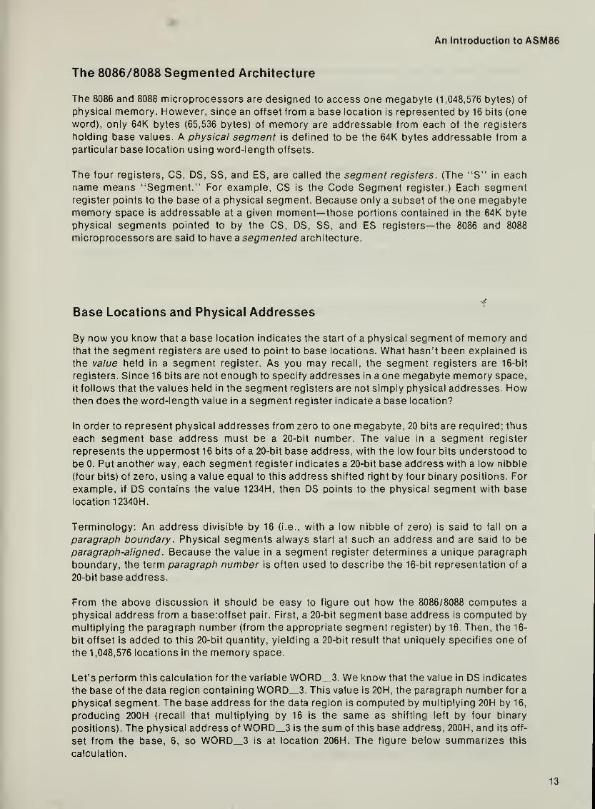
From the above discussion it should be easy to figure out how the 8086/8088 computes a
physical address from a base:offset pair. First, a 20-bit segment base address is computed by
multiplying the paragraph number (from the appropriate segment register) by 16. Then, the 16-
bit offset is added to this 20-bit quantity, yielding a 20-bit result that uniquely specifies one of
the 1,048,576 locations in the memory space.
Let's perform this calculation for the variable W0RD_3. We know that the value in DS indicates
the base of the data region containing W0RD„3. This value is 20H, the paragraph number for a
physical segment. The base address for the data region is computed by multiplying 20H by 16,
producing 200H (recall that multiplying by 16 is the same as shifting left by four binary
positions). The physical address of W0RD_3 is the sum of this base address, 200H, and its off-
set from the base, 6, so W0RD_3 is at location 206H. The figure below summarizes this
calculation.
13

er 2 Segmentation
+200 H6H
DS X 16+ OFFSET OF WORD 3
206H PHYSICAL ADDRESS OF WORD 3
Figure 2-7. Calculating the Physical Address of WORD 3 121689-7
it is important to note that computation of physical addresses from segment register and offset
values, as described above, is a function performed by the 8086/8088 CPU automatically. As an
assembly language programmer, you will only be concerned with loading appropriate values
into the segment registers and providing the proper offsets. The remainder of this chapter
explains how this is done in an ASM86 program.
Intel's assembly language for the 8086 and 8088 introduces the concept of a logical segment,
meaning a "piece of a program." Logical segments reflect the programmer's view of a pro-
gram as being composed of distinct code, data, and stack regions. In fact, a simple program
would consist of only three logical segments: one for machine code, one for variables, and one
for the run-time stack.
Logical segments (a feature of the assembly language) are related to physical segments (a
feature of the 8086/8088 architecture). Each logical segment in an ASM86 program defines a
region that will be addressed from a single segment register value. This means that a logical
segment is a programmer's specification of some or all of the contents of a physical segment.
Since the emphasis is on writing ASM86 code, the segments discussed in the remainder of this
manual will generally be logical segments.
An ASM86 source file usually contains several logical segments. Each segment begins with a
SEGMENT statement and ends with an ENDS statement. The syntax for the SEGMENT and
ENDS statements is given below.
The Segment and End-Segment Statements
segname SEGMENT [attribute-list]
segname ENDS
The segname is an identifier used as a symbolic name for the segment. The segnames on
corresponding SEGMENT and ENDS statements must match each other. The attribute-list field
is optional and is used when a program is divided into several source files. The attribute-list
will not be used or further discussed until Chapter 4.
THE ASM86 PROGRAMMER'S VIEW OF SEGMENTATION
Another Kind of Segment
The SEGMENT and ENDS Statements
An Introduction to ASM86
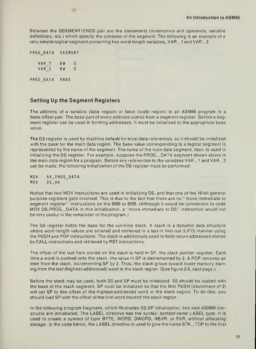
Between the SEGMENT/ENDS pair are the statements (mnemonics and operands, variable
definitions, etc.) which specify the contents of the segment. The following is an example of a
very simple logical segment containing two word-length variables, VAR_1 and \/AR_2.
PROG_DATA SEGMENT
VAR_1 DW 0
VAR_2 DW 0
PROG DATA ENDS
Setting Up the Segment Registers
The address of a variable (data region) or label (code region) in an ASM86 program is a
base:offset pair. The base part of every address comes from a segment register. Before a seg-
ment register can be used in forming addresses, it must be initialized to the appropriate base
value.
The DS register is used by machine default for most data references, so it should be initialized
with the base for the main data region. The base value corresponding to a logical segment is
represented by the name of the segment. The name of the main data segment, then, is used in
initializing the DS register. For example, suppose the PROG^DATA segment shown above is
the main data region for a program. Before any references to the variables VAR_1 and VAR_2can be made, the following initialization of the DS register must be performed:
MOV AX,PROG_DATAMOV DS.AX
Notice that two MOV instructions are used in initializing DS, and that one of the 16-bit general
purpose registers gets involved. This is due to the fact that there are no "move immediate to
segment register" instructions on the 8086 or 8088. (Although it would be convenient to codeMOV DS,PROG^DATA in this initialization, a "move immediate to DS" instruction would not
be very useful in the remainder of the program.)
The SS register holds the base for the run-time stack. A stack is a dynamic data structure
where word-length values are entered and retrieved in a last-in first-out (LIFO) manner using
the PUSH and POP instructions. The stack is additionally used to hold return addresses stored
by CALL instructions and retrieved by RET instructions.
The offset of the last item stored on the stack is held in SP, the stack pointer register. Eachtime a word is pushed onto the stack, the value in SP is decremented by 2. A POP removes an
item from the stack, incrementing SP by 2. Thus, the stack grows toward lower memory start-
ing from the last (highest-addressed) word in the stack region. (See figure 2-8, next page.)
Before the stack may be used, both SS and SP must be initialized. SS should be loaded with
the base of the stack segment. SP must be initialized so that the first PUSH (decrement of 2)
will set SP to the offset of the highest-addressed word in the stack region. To do this, you
should load SP with the offset of the first word beyond the stack region.
In the following program fragment, which illustrates SS:SP initialization, two new ASM86 con-
structs are introduced. The LABEL directive has the syntax: symbol-name LABEL type. It is
used to create a symbol of type BYTE, WORD, DWORD, NEAR, or FAR, without allocating
storage. In the code below, the LABEL directive is used to give the name STK_TOP to the first
15

Chapter 2 Segmentation
PUSH AXDECREMENTS SP BY 2.
THEN STORES THE VALUEOF AX ATSS;SP
(old SP) r
I
SP
SS
AX VALUE
POP AXLOADS AX WITH THE VALUEAT SS;SP. THEN INCREMENTSSP BY 2.
- (oldSP)
SP
SS
Figure 2-8. The Run-Time Stack 121689-8
word beyond the contents of the PROG_STACK segment. The OFFSET operator, whenapplied to a variable or label name, returns a constant equal to the offset of the variable or label
from the start of its segment. Thus, OFFSET STK_TOP, to which SP is initialized, refers to the
offset of the first word beyond the stack region. SS is initialized to PROG^STACK, a symbol
representing the base of the stack segment.
PROG STACK SEGMENT
STK TOP
DM
LABEL0,0,0,0,0WORD
Five wordsFirst word
in stack.
BEYOND stack region,
PROG STACK ENDS
MOV AX , PROG_STACKMOV SS.AXMOV SP, OFFSET STK_TOP SS:SP reflects an empty stack
The initialization of the DS, SS, and SP registers is typically the first code executed in a pro-
gram, since data and stack references in the rest of the program rely on the fact that these
registers have been properly set up. This raises a new question: How do you indicate whereyour assembly language program starts?
The 8086 and 8088 use a pair of registers, OS and IP, to mark the current point of execution. The
OS register holds the base for the code segment, a region containing machine instructions.
The value in IP, the instruction pointer register, is the offset (within the code segment) of the
instruction to be executed.
16

An Introduction to ASM86
In order for your program to be executed, the CS and IP registers must be set up to point to the
first instruction in the program. This initialization is performed by the program loader (file-
based systems) or bootstrap code (ROM-based systems). When writing an ASM86 program,
you need only indicate where your program begins. To do this, mark the first instruction to be
executed with a label (a symbol followed by a colon), then refer to this label in the optional
start-address field of the END statement. This field is to the right of the l^eyword END, as
shown in the syntax diagram below:
The END Statement
END [start-address]
A source file in which a start-address is specified is called amain module. When a program is
divided into several source files (modules), only one will be the main module for the program(since a program can have only one start address!). Programming with multiple modules is
discussed in Chapter 4. Until then, all example programs will consist of a single source file—
a
main module—and will thus specify a start-address
.
In the following program fragment, the label START is used in the END statement to indicate
that MOV AX,PROG_DATA is the first instruction to be executed. Notice that the programbegins by setting up the DS, SS, and SP registers with the same initialization code shownpreviously.
PROG CODE SEGMENT
START: MOV AX,PROG_DATA
PR06_C0DE ENDS
END START ;Program begins with instruction labelled by START.
Changing Segment Register Values
The values in the four segment registers (CS, DS, SS, and ES) determine the code, data, stack,
and extra regions currently accessible by your program. You are likely to use the same stack
region throughout your program, but you may want to access code or data in several different
regions. In order to change the current address space so that it includes a new region, one of
the segment registers must be reloaded.
The DS register holds the base for the main data segment. If you need to access a variable out-
side this region, you have two choices: you may reload DS or you may use ES to address the
variable. If you choose to reload DS (using a MOV, POP, or LDS instruction), you will be chang-
ing your program's main data region so that it includes a whole new set of variables. Since you
will probably want to refer to the previous data region again, you should save the value of DS
prior to reloading it. This save/restore overhead makes changing DS impractical for occasional
references to variables outside the main data segment.
MOV
MOV
MOV
MOV
DS.AXAX , PROG_STACKSS, AX
SP, OFFSET STK_TOP
17

er2 Segmentation
A special instruction byte, the segment override prefix byte , can be used to tell the 8086 or 8088
that a segment register ottier than DS is to be used in forming the address of a variable. This
prefix byte may be explicitly coded (see Chapter 3) or automatically generated by the
assembler (see "The ASSUME Statement" below). A common use of the segment override
prefix byte is to specify that ES, rather than DS, is to be used for the base part of a variable
address. Since loading ES (using a fVlOV, POP, or LES instruction) does not alter your pro-
gram's main data region, and since ES need not be saved and restored, the ES register should
be used for occasional references to variables outside the DS-addressed main data segment.
Control transfer instructions (JMP, CALL, RET, etc.) are used to direct your program to a newpoint of execution. For example, a JMP instruction breaks the current instruction sequenceand causes execution to resume elsewhere in the program code. Program control can be
transferred within the current code segment or to a new code segment. For a control transfer
within the current code segment, only the value of IP is changed. When control is transferred
to a new code segment, both CS and IP are changed.
The assembler uses the type of the label operand for the CALL and JMP instructions to deter-
mine whether to produce an opcode that changes only IP, or an opcdde that changes both CSand IP. A label should be given type NEAR if only IP needs to be changed to access the label.
In other words, jumps and calls within the current code segment are always to NEAR labels. Asimple code label (a symbol followed by a colon) is considered to have type NEAR. A label to
be accessed from a different code segment should be given type FAR, indicating that both CSand IP will have to be changed in order to transfer control to the label. Labels of either type
NEAR or FAR may be defined using the LABEL directive (described earlier) or the PROC direc-
tive (described in Chapter 4).
As an example of how type information is used to decide whether a JMP should alter only IP or
both CS and IP, consider the following program fragment:
CODE SEGMENT
N_LAB: MOV AX.BX
JMP N LAB
COO'. ENDS
I', this example, the label N LAB has type NEAR, since it is defined using a colon. Thus, the
JMP N__LAB instruction statement will produce an opcode that changes only IP. This is
appropriate, since the MOV instruction labelled by N„LAB and the JMP N_LAB instruction
are in the same code segment; i.e., they use the same value of CS.
The ASSUME Statement
In order to correctly generate instructions which access memory, the ASM86 assembler needsinformation about the base values loaded into the segment registers. Using this information,
the assembler can decide which of the segment registers can be used in addressing a par-
ticular memory location and if a segment override prefix byte is necessary. If none of the seg-
An Introduction to ASM86
ment registers can be used in forming an operand address, the assembler produces an error
message.
This information about the contents of the segment registers is provided in the ASSUME state-
ment, which has the following syntax:
Assume Statement
ASSUME segreg-.base-value[ ,segreg.base-value ]...
The segreg field is the name of a segment register: CS, DS, SS, or ES. The base-value in-
dicates the region addressable from the segment register. One type of base-value is a seg-
ment name, as in:
ASSUME DS : PROG_DATA
This ASSUME statement tells the assembler that variables defined in the PROG„DATA seg-
ment may be addressed using offsets from DS. Seeing this ASSUME statement, the assembleralso learns (by implication) that DS cannot be used in accessing any other segment.
A special base-value option is the keyword NOTHING. Saying that NOTHING is in a segmentregister tells the assembler not to generate instructions which use this segment register to
access memory, since the segment register has not been loaded with a usable base value.
Initially, NOTHING is assumed for all of the segment registers. It is therefore important that
you put an ASSUME statement in your source module, prior to any memory accessing instruc-
tions, to tell the assembler the true state of the segment register contents.
As indicated in the example above, the DS-assume identifies a program's main data region. All
variables defined in this region will be addressed using DS. If an ASSUME for ES is in effect, an
additional data region is identified, which contains variables that must be addressed using ES.
Using this information, the assembler will automatically generate an ES segment override
prefix byte for instructions that access variables in this extra data region. The SS-assume is
similar: ordinary data references to this region will require an SS segment override prefix byte.
The OS-assume indicates the segment currently accessible from the CS register (a module
may contain more than one code segment). Labels of type NEAR may only be defined in a seg-
ment to which the CS-assume applies. Also, any data references to locations in this segmentwill automatically generate a CS segment override prefix byte.
It should be emphasized that the ASSUME statement is used only to tell the assembler what it
should assume about the segment register contents. This directive does not generate code; it
is up to you to properly initialize the segment registers.
EXAMPLE PROGRAM
The program that follows (figure 2-9, next page) is a comp/efe, though very simple, ASM86 source
module. It is intended to illustrate the use of the SEGMENT/ENDS and ASSUME statements.
The important features of this example program are highlighted in the discussion below.
The first thing to notice about the example program is that it is composed of three distinct
logical segments: PROG DATA, PROG„_STACK, and PROG CODE. Each segment begins
with a SEGMENT statement and ends with an ENDS statement. The ASSUME statement near
the top of the program indicates that CS will hold the base for PROG CODE, the code seg-
ment, and DS will point to the base of PROG_DATA, the data segment. (NOTHING is assumed
19

Chapter 2 Segmentation
NAME EXAMPLE_2
ASSUME CS : PROG_CODE ,DS:PROG_DATA
PROG_DATA SEGMENT
VAR_1 DW 0
VAR_2 DW 0
PROG_DATA ENDS
PROG_STACK SEGMENT
DW 10 DUP (?)
STK_TOP LABEL WORD
PROG_STACK ENDS
PROG CODE SEGMENT
MOV AX , PROG_DATAMOV DS , AX ; Initialize DS.
MOV AX, PROG STACK
MOV SS.AX ; Initialize SS.
MOV SP, OFFSET STK_TOP ; Initialize SP for empty stack
PUSH AX ; The following code loops.
MOV AX, VAR_1
ADD AX,
5
MOV VAR_2, AX
POP AX
JNP MAIN
PR06_C0DE ENDS
END BEGIN
Figure 2-9. A Simple ASM86 Module Using the SEGMENT/ENDS and ASSUME Statements
for SS and ES, since these segment registers will not be used in addressing variables.) In the
following diagram (figure 2-10, opposite page), all but the ASSUME and SEGfvlENT/ENDSstatements have been removed so that the information supplied to the assembler by these
statements can be clearly shown.
Examine the contents of the three segments. The first segment, PROG DATA, contains two
variables, VAR_1 and \/AR_2, defined using DW statements. This simple program, then, has
only two words of storage in its main data region.
The first line inside PROG^STACK is a rather strange looking DW statement:
DW 10 DUP C)
20

An Introduction to ASM86
ASSUME CS : PROG_CODE , DS:PROG DATA
iTells the assembler that
variables in PROG_DA TA useDS for their base part.
Tells the assembler that
PROG_CODE is the current
code segment, with base in CS.
PROG DATA SEGMENT
Data segment:
contains variables
PROG DATA ENDS
PROG STACK SEGMENT
Stack segment:
defines a block of storage
PROG STACK ENDS
PROG CODE SEGMENT
Code segment:
contains instructions
PROG CODE ENDS
Figure 2-10. The ASSUME and SEGMENT/ENDS Statements in the Example Program
This statement reserves ten words of uninitialized storage. The 10 DUP says, 'Give me 10
copies of the value in parentheses." The question mark is used to indicate an uninitialized
value. Thus, the stack in the example program is ten words deep.
The next statement in PROG_STACK is a LABEL directive:
STK TOP LABEL WORD
21

I

I


CHAPTERSDATA
This chapter describes the ASM86 constructs used to allocate and access the data portion of
your assembly language program. The topics of data allocation, addressing modes, and
attribute overrides are covered in detail because, in order to write even simple programs, you
will need a good working knowledge of these subjects.
DATA ALLOCATION
The 8086 and 8088 microprocessors support three fundamental data types: byte, word, and
double-word. A byte is eight bits, a word is sixteen bits (two bytes), and a double-word is
thirty-two bits (two words). The ASM86 data allocation statement is used to specify the bytes,
words, and double-words which your program will use as data. We have already seen several
simple data allocation statements in previous chapters. What follows is the general syntax for
the data allocation statement, and a discussion of how this statement specifies initial values
for program data.
Data Allocation Statement
\var-name\
DBDWDD
in it[
, in it
The DB statement is used to reserve bytes of storage, DW words, and DD double-words. Theinit field, to the right of the DB, DW, or DD, serves two purposes. It specifies how many bytes,
words, or double-words are allocated by the statement, as well as what their initial values
should be. As indicated above, the init field may contain a single init or a list of inits, separated
by commas. One kind of init is an expression indicating the initialization value for a single unit
of storage, if you don't care what initialization value is used, you can use ? for an init.
Examples of single-unit /n/Ys are as follows:
DW 5 ; allocate one word, initialized to 5
OB 1, 0 ; allocate three bytes, second value unimportant
A variable or label name may be used as an init in either a DW or DD statement. In a DW state-
ment, such an init specifies an initialization value equal to the offset of the variable or label
from its segment. In a DD statement, the initialization value is the complete base:offset
address of the variable or label, with the offset occupying the lower-addressed word.


I

Chapters Data
Before we go on to the next addressing mode, another point should be made regarding the
above CMP instruction. Recall the data allocation statement used to define VAR„2:
VAR_2 DB 1, 2, 3
You may wonder how the second and third bytes allocated with this statement will be
accessed, since they cannot be accessed directly with a variable name. The expression
\/AR_2 + 1 used in the CMP instruction is one way of accessing the byte that follows VAR_2.
The variable specified by VAR_2 + 1 has the same type and segment as VAR_2 (BYTE,
PROG DATA), but has an offset equal to one more than the offset of VAR_2. It should be ob-
vious that the third byte (initialized to 3) could be accessed using the expression VAR 2 + 2.
Indirect Addressing
A second kind of addressing mode is often called indirect addressing , since the offset part of
the memory address comes from a register, rather than a field in the instruction. Four of the
word-length 8086/8088 registers can be used for indirect addressing: BX, BP, SI, and Dl.
Indirect-mode memory addresses use DS as the default segment register, except for cases
where BP is used, when the default segment register is SS. The following are examples of
instructions that use indirect addressing:
MOV AX,[BX]
ADD [Sn.DL
Notice the use of brackets to signify this indirection. The instruction MOV AX,BX says, "Load
the AX register with the contents of the BX register." When the brackets are present, the
meaning is changed. The instruction MOV AX,[BX] says, "Load the AX register with the word
in memory specified by the offset in register BX."
The advantage of indirect addressing lies in the fact that, since the offset is in a register rather
than frozen into the instruction, the offset may be altered at run-time. The following program
excerpt illustrates the utility of the indirect addressing mode:
(data definition)
NUMBERS DB 0,1,2,3,4,5,6,7,8,9
(code fragment)
MOV BX, OFFSET NUMBERS [BX] is offset for first data byte.
MOV CX,10 CX is the loop counter
.
MOV AL,30H Constant used for ASCII conversion.
ADD [BX] , AL Convert number to ASCII character.
INC BX Point BX at next number.
LOOP ASCII Continue until counter is zero.
28

An Introduction to ASM86
The above loop, when executed, converts the ten bytes with values 0 through 9 to ASCII
characters by adding the value 30H to each of them, initially [BX] specifies the offset of the first
data byte. Each time through the loop BX is incremented, causing (BX) to become the offset of
the next byte. It is easy to see that this loop is a significant improvement over the code-wasting
alternative:
ADD NUMBERS, 30H
ADD NUMBERS + 1 ,30H
Other advantages of such a loop are that the initial offset and counter values may be set at run-
time. For example, the loop code above (minus the first two tVlOV instructions) could be used
as part of a procedure designed to convert a string of numbers (values between 0 and 9) to
ASCII, with the initial offset and loop counter (length of the string) passed in as parameters.
Register-Offset Addressing
The register-offset addressing mode uses a value in a register ancy an offset in the 8086/8088
instruction. In this case, the offset part of the memory address is the sum of the register value
and the offset encoded in the instruction. As with indirect addressing, the registers which can
be used are BX, BP, SI, and Dl, and the default segment register is DS for all but BP, which
uses SS. Below are two examples where the register-offset addressing mode is used:
MOV AX,[BP+6]SUB VAR_2[DI],17
Again notice that brackets indicate a register used for addressing. The first example, MOVAX,[BP + 6], addresses the location six bytes beyond SS:BP. If SS:BP is used to point to the
base of a data structure, then [BP + 6] can be thought of as "offset 6" within the data structure.
The second example, SUB VAR_2[DI],17, uses the value in Dl together with the offset of
\/AR_2 in order to form a memory address. In this case, Dl can be thought of as being an index
value, an offset from the location named by \/AR_2.
The following is a minor modification of the program excerpt used to convert the NUMBERSarray to ASCII characters. This time, register-offset addressing is used, with BX holding the
index into the NUMBERS array. Also, for variety, the constant used to make the adjustment
(30H) is part of the ADD instruction.
(data definition)
NUMBERS DB 0,1,2,3,4,5,6,7,8,9
(code fragment)
MOV BX,0
MOV CX,10
ASCII: ADD NUMB E R S [ B X ] , 3 0
H
INC BX
LOOP ASCII
[BX] is index for first data byte
CX is the Loop counter
.
Convert number to ASCII characterI nc rement array index.
Continue until counter is zero.

er3 Data
Addressing Through Two Registers
The 8086/8088 also supports addressing modes involving two registers and, optionally, an off-
set encoded in the instruction. Again, the registers used in addressing are BX, BP, SI, and Dl.
The pairs allowed are combinations of BX or BP with either SI or Dl. When BX is used, the
default segment register is DS, and with BP it is SS. Again, the offset, used together with the
base value from a segment register to form an address, is the sum of the register values and,
possibly, an offset encoded in the instruction. Examples follow;
MOV AX,[BX][OI]ADD [BP-12] [Sn ,BL
CMP VAR_1 [BX] [S I ] , 1 234H
MOV DX,[BP][DI]
The above examples show the various allowable combinations of the BX/BP and SI/DI
registers. The first and last (both fvlOV instructions) use no offset field in the instruction, so the
offset part of the memory address will be the sum of the values in two registers. The ADD andCfVlP instructions use two registers along with an offset encoded in the instruction in specify-
ing a memory address. Again notice the brackets; when more than one bracketed expression
occurs, the sum of the two expressions is indicated. For example, the two expressions
[BX][DI][5] and [BX-i-DI + 5] are equivalent.
Summary of Addressing Modes
The following table briefly summarizes the addressing modes available on the 8086/8088:
Table 3-1 . Addressing Modes on the 8086/8088
Addressing Mode Form and Alternatives Examples
direct offset <instr> MOV AX , VAR_1
indirect <reg>BX / BP* / SI/DI
MOV AX , [ BX
]
register-offset <reg> + <instr>
BX + c / BP + c* / Sl + c / Dl + c
MOVMOV
AX , [ BX + 1 0 ]
AX , VAR_1 [ BX
]
two registers <reg> + <reg>BX + SI / BX + DI
BP + SI* / BP + DI*
MOV AX , [ BX ] [ s n
two registers
with offset
<reg> + <reg> + <instr>
BX + SI + c / BX + DI + c
BP + SI + c* / BP + DI + c*
MOVMOV
AX,[BX][SI+10]AX , VAR_1 [ BX ] [ S I
]
Key to symbols:
<instr>, c — indicates offset field encoded in the instruction
<reg> — indicates that a register is used for addressing* — addressing modes involving BP use SS as the default segment register;
the others default to DS.
ATTRIBUTE OVERRIDES
As we have seen, a variable has three attributes: a type, a segment, and an offset within the
segment. ASM86 allows you to temporarily change either the type or segment associated with
a variable through the use of special attribute override operators. In the discussion that
follows, both the segment override and the type override are discussed.

An Introduction to ASM86
Segment Overrides
Suppose you are writing an assembly language program with several different data regions,
each addressable from a different base value. Let's say, for example, that there are four such
data regions, corresponding to logical segments called DATA_MAIN, DATA_1, DATA_2, and
DATA_3. The DATA„MAIN segment contains commonly used variables, so DS is used to hold
its base. The program's initialization code will load DS with DATA_MAIN and an ASSUMEDS:DATA_MAiN will remain in effect for the duration of the program.
The other data regions will be accessed only occasionally, so ES will be used as the segmentregister pointing to these extra data segments. Each time the extra segment changes, as whenyou stop referencing DATA_1 and want to start referencing DATA_2, your code must reload
the ES register. How do you tell the assembler that ES is to be used in instructions referencing
variables in DATA_2? One method would be to use the ASSUME statement to provide this
information: ASSUME ES:DATA^2.
However, there is an alternative that can be more convenient when only a few references
through ES are needed. This alternative is the segment override operator, which is merely a
segment register name, followed by a colon (:), placed in front of the variable name. This
operator tells the assembler which segment register to use in addressing the variable in this
particular instance. For example, if VAR_2 is a variable in DATA_2 and ES holds the base for
DATA_2, then an instruction to increment VAR_2 could be coded as:
INC ES:VAR_2
When used with variables, as shown above, the segment override operator serves as a short-
term (one instruction only) ASSUME statement. In effect, the segment override says, "Nomatter what the previous ASSUME statement says, use this segment register." Thus, even if
the program contained the statement ASSUME DS:DATA_2, the instruction INC ES:VAR_2would use the ES register.
The segment override operator may also be used with anonymous references; i.e., memoryaddresses specified without a variable name. For example, the indirect address [BX] will use
the base in DS by (machine) default, but may be changed to use ES by prefixing the instruction
with a segment override prefix byte. This need for a prefix byte is indicated in the assembly
language by coding a segment override operator in front of the memory reference, as in the
following example:
MOV AX,ES:CBX]
Although the segment override operator and the segment override prefix byte seem closely
related, the use of the segment override operator does not guarantee that a segment override
prefix byte will be generated. The segment override operator tells the assembler which seg-
ment register should be used in addressing memory. The assembler may determine from this
information that no segment override prefix byte is needed for tiiis instruction. For example,
suppose you code the following instruction:
MOV AX,SS:[BP+8]
The assembler is told to generate an instruction which uses SS as the segment register to be
combined with [BP-i-8] in forming an address. Since SS is the (machine) default for a reference
involving BP, no segment override prefix byte is necessary; the assembler will not generate an
SS-prefix.
31

er3 Data
To summarize: The ASM86 assembler uses the information in ASSUME statements to decide
which segment register should be used in addressing variables, and assumes the machine
default is acceptable for anonymous references where registers are used for addressing. The
segment override operator tells the assembler explicitly which segment register should be
used for a particular instruction. Using this information, the assembler will generate an
instruction that uses the segment register indicated. The instruction generated will contain a
segment override prefix byte only if it is necessary to override the machine's default selection
of a segment register.
Type Overrides
Each variable has associated with it a type which indicates the number of bytes referenced by
the symbol. The type of a variable tells the assembler what kind of instructions to generate for
the variable. For example, if VAR_1 has type WORD, then MOV \/AR_1,5 specifies that a 16-
bit constant with value 5 should be placed at the location indicated by VAR„1 . Additionally, the
type of VAR_1 can be used to tell whether you are unintentionally misusing this WORDvariable. For instance, the assembler will produce an error message if you code MOVVAR_1 , AL, since AL is a BYTE register and VAR_1 is a WORD variable.
If you want to code something like MOV VAR^I ,AL, or to have MOV VAR_1 ,5 produce a BYTEinstruction, then you must make it clear that you are referring to the first BYTE of the word
variable. VAR_1. To do this, use the type override operator. The syntax of the type override
operator is as follows:
BYTE)WORD \ PTR var-name
DWORD J
The expression type PTR var-name means. "Use the segment and offset of the variable with
name var-name, but with the type explicitly given.'" For example, the two operations on the
first BYTE of VAR_1 would be coded as shown below:
MOV BYTE PTR VAR_1 , AL
MOV BYTE PTR VAR_1 ,
5
The type override operator is also used to resolve the ambiguity sometimes present with
anonymous references. For example, consider the following instruction statements:
MOV [BX],3INC [BP+6]
Since both BYTE and WORD versions of the MOV and INC instructions exist, and since neither
of these instruction statements tells the assembler whether BYTE or WORD is intended, both
instruction statements are ambiguous—they will produce error messages. If the MOV is to be a
BYTE operation and the INC a WORD operation, you must make this clear, as follows:
MOV BYTE PTR [BX],3INC WORD PTR [BP+6]
Note that not all anonymous references result in ambiguity. When two operands are present,
only one needs to convey type information. Thus, the statement MOV [BX],AX indicates a
WORD operation due to the fact that AX is a WORD register. In this case, the fact that [BX]
conveys no type information is unimportant.

An Introduction to ASM86
To summarize: The ASM86 assembler uses the type information from variables and register
operands to determine whether an instruction operates on a byte, word, or double-word. Whenyou want to refer to a named location using a type other than the one given to the variable
when it was defined, you need to explicitly override the type attribute with the PTR operator.
With some instructions, a simple anonymous reference to memory does not distinguish
between the BYTE and WORD operations. In this case, the type override operator is needed to
explicitly indicate whether BYTE or WORD is intended.
The following program is a simple ASM86 source module which demonstrates the concepts
covered in this chapter: data allocation, addressing modes, and both segment and type over-
rides. The function performed by this program is to convert an unpacked representation of a
number (in this case, eight bytes with one decimal digit per byte) to a packed representation
(four bytes with two digits per byte—one per nibble). For the sake of illustration, the unpaddednumber lies in a data region other than the main (DS-based) data region, so ES is used to hold
its base. As you examine the program, notice the addressing modes and overrides used.
Following the program listing is a discussion highlighting the important features of the
module.
NAME EXAMPLE_3
ASSUME CS : PROG_CODE,DS:MAIN_DATA
MAIN DATA SEGMENT
EXAMPLE PROGRAM
PACKED NUMBERDW '
DB 4 DUP (0)
MAIN DATA ENDS
OTHER DATA SEGMENT
DW 2 DUP C)UNPACKED_NUMBER 08 8,7,6,5,4,3,2,1
OTHER DATA ENDS
PROG CODE SEGMENT
PROG START:MOV
MOV
MOV
MOV
MOV
AX,MAIN_DATADS , AX
AX ,OTHER_DATA
ES , AX
BX, OFFSET PACKED_NUMBER
DS is MAIN DATA base.
ES is OTHER_DATA base.
DS: [BX] addresses the
start of PACKED NUMBER.
Figure 3-1 . A Simple ASM86 Module Demonstrating Data Definition,
Addressing Modes, and Attribute Overrides
33

Chapters Data
PACK:
MOV
MOV
MOV
MOV
SHL
SHL
SHL
SHL
ADO
MOV
ADD
INC
LOOP
HLT
S I , 0
01 , SI
CX,4AX, WORD
AH , 1
AH , 1
AH, 1
AH , 1
AL, AH
[BX] [DI]
SI , 2
DI
PACK
PTR ES:UNPACKEO
AL
Source Index (init. 0)
Dest . Index (init. 0)
Loop counter (init. 4)
.NUMBER[SI]
; Fetch two unpacked bytes
AH := 16 * (higher byte)Pack two bytes into one.
Store the packed byte.SI will i ndex next WORD.DI will index next BYTE.Do until counter = 0.
<end of progrann>
PROG CODE ENDS
END PROG START
Figure 3-1 . A Simple ASM86 Module Demonstrating Data Definition,
Addressing Modes, and Attribute Overrides (Cont'd.)
First, look at the definition of the variable PACKED_NUMBER:
PACKED_NUMBER DB 4 DUP (0)
This statement defines a variable with type BYTE, segment MAIN_DATA (since the statement
is within the SEGMENT/ENDS pair for MAIN_DATA), and offset 2. The DUP construct is used
here to initialize four bytes to zero, the four bytes which will be used to hold a packedrepresentation of a decimal number.
The other variable in this program, UNPACKED NUMBER, is defined in another segment,
using a list of initialization values:
UNPACKED_NUMBER DB 8,7,6,5,4,3,2,1
This variable also has type BYTE. Its segment is OTHER DATA and its offset within the seg-
ment is 4. The initialization list allocates eight bytes which can be thought of as an unpackedrepresentation of an eight-digit decimal number with value 12345678 (assuming that higher-
addressed positions represent greater powers of ten).
The DW statements preceding the variable definitions are not really needed by the program,
but were provided for the purposes of illustration. Because both variables are preceded by
other data allocation statements, they each have a nonzero offset (as already mentioned). TheDW statements are also useful for pointing out the significance of the ? init. The first DW state-
ment, DW ?, allocates one word of storage, initialized to an indeterminite value. The other DWstatement, DW 2 DUP (?), uses the special construct n DUP (?) to allocate two uninitialized
words.
34

An Introduction to ASM86
Now, let's move on to the code, which the END statement tells us will begin at the location
labelled PROG _START. The first four lines are segment register initializations:
PROG_START:MOV AX,MAIN_DATA
When this initialization sequence is executed, the DS register is loaded with the base of the
MAIN_DATA segment, allowing DS to be used in addressing PACKED_NUMBER. The basefor OTHER_DATA is loaded into ES, so instructions referencing UNPACKED^NUMBER will
require an ES prefix byte. SS and SP are not initialized, since this example program uses no
stack. (This is unusual; almost all programs need to initialize SS:SP.)
Now, skip ahead to the first instruction of the loop:
PACK: MOV AX, WORD PTR E S : UN P A C K E D_N UM B E R [ S 1]
; Fetch two unpacked bytes.
This instruction uses the register-offset addressing mode, with both the contents of the SI
register and the offset of UNPACKED_NUMBER entering into the address calculation. A seg-
ment override operator, ES:, tells the assembler to produce an instruction which uses ES for
the base part of the UNPACKED___NUMBER address. (Notice that, by default, ASSUMEES:NOTHING is in effect.) Finally, because it is desirable for efficiency, two bytes from
UNPACKED„NUMBER are fetched at one time. Since the type of UNPACKED NUMBER is
BYTE (it is defined using a DB statement), a type override operator is needed to tell the
assembler that a WORD reference is intended.
In this program, the value of SI is used as a source index. If you think of
UNPACKED„NUMBER as an array, then SI is an offset into this array. Notice that SI is initial-
ized to zero and, since UNPACKED NUMBER is accessed a WORD at a time, the value of SI is
adjusted by two each time through the loop:
MOV SI,0 ; Source Index (init. 0)
ADD SI, 2 ; SI will index next WORD.
For the sake of illustration, the PACKED NUMBER array is accesssed using a two-register
addressing mode. First, BX is initialized to the offset of PACKED_NUMBER, so that DS:[BX]
will address the start of the PACKED_NUMBER array:
MOV BX, OFFSET P A C K E D_N UM B E R ; DS:[BX] addresses the
; start of P A C K E D_NUMB E R
.
The Dl register will be used as the destination index, that is, an offset into the
PACKED„NUMBER array. Thus, the bytes in PACKED_NUMBER are addressed using a com-
bination of the values in the BX and Dl registers:
MOV [BX][DI],AL ; Store the packed byte.
MOV
MOV
MOV
DS , AX
AX , OTHER_DATAES , AX
DS is MAIN DATA base.
ES is OTHER DATA base.
35

Chapters Data
Notice that the above instruction contains no attribute override operators. The segmentregister needed to form an address for PACKED NUIVIBER is DS, which is the default for two-
register references using BX, so no segment override operator is required. The anonymousreference (BXKDI) contains no type information, but the use of AL as an operand tells the
assembler that a BYTE operation is intended, so no type override operator is necessary.
The Dl register, used in accessing the bytes of PACKED NUf\/IBER, is initialized to zero (by
moving the initial value of SI, also zero, into Dl). Each time through the loop, Dl is incremented
(by one), since PACKED_NUMBER is being accessed a BYTE at a time.
MOV DI,SI ; Dest. Index (init. 0)
INC Dl ;DIwiUindexnextBYTE.
Once again, CX is used as a loop counter. Initially CX is set to four, since only one of the four
PACKED NUMBER bytes is computed each time through the loop. The loop structure is
outlined below:
MOV CX,4;
Loop counter (init. 4)
PACK:
LOOP PACK ; Do until counter = 0.
Except for the HLT instruction (used here to mark the end of the program), the rest of the
instructions are used in packing two decimal digits from two separate bytes into one byte. This
is done by shifting the more significant digit into the upper nibble (four bits) of AH, then adding
AH to AL, creating a byte with one digit in each nibble:
SHL AH,1SHL AH,1SHL AH,1SHL AH,1 ; AH := 16 * (higher byte).ADD AL.AH ; Pack two bytes into one.
Like the example in Chapter 2, the framework for this module consists of the NAME, ASSUME,SEGMENT/ENDS, and END statements. These statements, as used here, should already befamiliar, so no elaboration will be given.
CHAPTER SUMMARY
The DB, DW, and DD statements are used to allocate storage for data and (optionally) assign
initial values. An ASM86 variable is a unit of program data with a symbolic name. Each variable
has an associated type, offset, and segment attribute. The attribute override operators are
used to specify the type or segment register involved in a particular memory reference. Oneuse of these operators is to override the attributes that are assigned to a variable when it is
defined.
The 8086 and 8088 microprocessors allow a variety of addressing modes. The offset part of anaddress may come from a field in the instruction, a register, a pair of registers, or a combina-tion of an offset in the instruction and one or two registers. The register modes are dynamic in
that they allow for programmatic manipulation of address components. This wide variety of
addressing modes makes accessing even complex data types (such as arrays) a rather simple
task.
36

CHAPTER 4MODULAR PROGRAMMING
A modular program is one that is made up of different pieces, whiere each piece can be
independently understood. There are two ways in which an ASM86 program can be modular:
(1) the program may be divided into several source modules (separately assembled files con-
taining the code and data for the program), and (2) the program may use procedures as func-
tional blocl<s to perform specific data transformations.
This chapter covers both types of program modularity. The first, and larger, part of the dis-
cussion deals with the methods used to recombine a program that has been split into several
different source modules. Here it is explained how variables and labels defined in one modulemay be referenced in another, and how logical segments may be combined so that their con-
tents are addressable from the same segment register value. Following this discussion is a
section devoted to the use of procedures, which shows how procedures are defined in ASM86,and introduces the topic of parameter passing.
PROGRAMMING WITH MULTIPLE SOURCE MODULES
Up to this point in the discussion, you have been lool^ing at small programs completely con-
tained in one ASM86 source module. While this single-module approach is appropriate for very
small programs— in particular, simple programs used for instructional purposes— the size and
complexity of most real-world applications maizes a multiple-module approach much moredesirable.
There are many advantages to developing a program as a collection of component modules.
One obvious reason for dividing a program into several modules is that smaller modules are
easier to manage: you have less text to search to find what you're looking for, and you do not
have to keep track of all the program symbols at once. Another advantage of multiple modules
is that you can design your modules to be functional blocks which are largely self-contained
and, thus, may be individually tested and debugged.
Yet another benefit of splitting a program into several modules is that you can code some of
your modules in a high-level language (such as PL/M-86, PASCAL-86, or FORTRAN-86). Con-
structing assembly language modules to work with modules written in PL/M-86 is the subject
of the next chapter.
Linking Modules Together
You may wonder, "If I split my program into several modules, how do I put it back together
again?" By using special directives in the assembly language, you can reference elements in
other modules (such as variables, labels, segments, etc.) and you can also make elements of
the current module available to other modules. These inter-module references hold the other-
wise fragmented program together.
Chapter 4 Modular Programming
Each source module that you create will be separately assembled (or compiled), producing an
object file unique to that module. When a source module contains references to other
modules, its object file will contain information about these inter-module references. It is the
job of a utility program called the linker (LINK86) to consolidate the individual object files that
make up a program into a single object file where inter-module references have been
resolved. Thus, getting a multi-module program into a form where it can be located or loaded is
a two-stage process: first, the individual source modules are assembled or compiled, then the
individual object files which make up the program are linked together (using LINK86) to form a
single object file.
The discussion that follows explains the assembly language constructs used in writing
multiple-module programs. The mechanics of linking object files together will not be covered.
Refer to the 8086 Family Utilities User's Guide or the iAPX 86,88 Family Utilities User's Guide
for information regarding the use of LINK86.
The PUBLIC and EXTRN Directives
Suppose you are developing a program made up of two modules: f\/IODULE 1 and
M0DULE__2. M0DULE_1 contains a byte variable, VAR_1, which you would like to access in
MODULE 2. To do this, a statement must first be put into f^0DULE_1, which says that
VAR_1 \s public (that is, available to other modules). This is done with the PUBLIC directive,
as shown below:
(inMODULE^I)
VAR_1 DB 0
PUBLIC VAR_1
Next, a statement in M0DULE_2 is needed to say that VAR_1 is a byte variable from another
module, an external symbol. You provide this information with the EXTRN directive, as follows:
(in M0DULE_2)
EXTRN VAR_1:BYTE
Notice that the EXTRN directive requires that type information be given, while the PUBLICdirective does not. The reason for this is very simple: the PUBLIC directive is used in the
module where VAR 1 is defined, so the assembler already knows the type of VAR 1. Since
the definition of VAR„1 is not seen in f\/IODULE_2, the EXTRN directive must provide the
necessary type information.
The general syntax of the PUBLIC and EXTRN statements is given below:
Public Statement
PUBLIC symbol [, symbol]...
External Statement
EXTRN symbol.type[ ,symbol.type ]...
The symbol used in the PUBLIC and EXTRN statements is the name of a variable, label (in the
code), or constant value (defined using EQU). The type will be either BYTE, WORD, or DWORDfor variables, NEAR or F.AR for labels, and ABS for constants.
38

An Introduction to ASM86
A note about the placement of EXTRNs: An EXTRN statement inside a SEGMENT/ENDS pair
tells the assembler that the external symbols listed belong in that particular logical segment. It
is important that you list external symbols belonging to segments in the current module inside
the proper SEGMENT/ENDS pairs and list other external symbols (belonging to none of the
logical segments in the current module) outside any SEGMENT/ENDS boundaries.
When the assembler sees a reference to an external symbol, it does not know the address or
value of the symbol, so it cannot generate an instruction in the usual manner. Instead, a
placeholder is put into the instruction and a record of this placeholder is put into the object file.
In the process of combining several object files into one. LINK86 sees these placeholder
records and, using the public symbol information also present, fills in the appropriate
addresses and values.
COMBINING LOGICAL SEGMENTS
Suppose that you are writing a two-module program, and that each of the modules contains
logical segments corresponding to code. data, and stack regions. Let's call these segments
C0DE_1, DATA_1. and STAGK_1 for M0DULE_1. and C0DE_2, DATA_2, and STACK_2for M0DULE„2. When the two object files are linked together, the layout of the resulting pro-
gram in memory will be as shown in figure 4-1 (below).
A problem with the situation depicted is that no two of the logical segments from M0DULE_1and M0DULE^2 are addressable from the same segment register. Thus, each time control
transfers between modules, the contents of CS must be changed. The two data regions must
be accessed either by constantly changing the value of DS to reflect the data region being
used, or by using DS to address one data region and ES to address the other (causing a pro-
fusion of segment override prefix bytes). Worse yet. since the program needs only one stack
region, the other will have to go unused!
STACK_2
DATA_2
CODE _2
STACK_1
DATA 1
CODE^I
Figure 4-1 . Uncombined Logical Segments from M0DULE_1 and MODULE 2 121689-9
39

Chapter 4 Modular Programming
Assuming that the combined size of the code segments is less than the size of a physical seg-
ment (64K), it would be efficient if they could be put together in such a way that the instructions
in both regions would be accessible from the same CS value. That way, all transfers of control
between modules would require only a change of the IP value, so the long forms of the CALLand JMP instructions could be avoided. A similar argument can be made in favor of combining
the data regions so that both are addressable from DS. The stacks, too, should be combined.
Figure 4-2 illustrates the combination of segments desired.
How can we get the segments from M0DULE_1 and MODULE 2 to combine correctly? The
answer lies in the SEGMENT statement. Recall the syntax of the SEGMENT and ENDSstatements, given in Chapter 2:
segname SEGMENT [attribute-list]
segname ENDS
First of all, the logical segments to be combined should have identical segnames. Thus, the
code regions in MODULE^I and M0DULE_2 should have a common name— for example,
PROG_CODE. The data and stack regions should also share common segnames. Let's use
the name PROG_DATA for the data regions and PROG_STACK for the stack regions.
The Attributes of Logical Segments
Up to this point, the attribute-list (in the SEGMENT statement) has not been used. The reason
for this is that the default attributes of a segment were acceptable in the simple cases where
no combining of logical segments occurred. Now that we want to combine segments, the
ss
DS
CS
STACK_2
STACK_1
DATA 2
DATA 1
CODE 2
CODE 1
121689-10
Figure 4-2. Desired Combination of Logical Segments from M0DULE_1 and M0DULE_2
40

An Introduction to ASM86
attribute-list becomes important. The attribute-list is composed of three fields, Vne align-type
,
combine-type , and class-name, as shiown in the expanded SEGMENT/ENDS syntax given
below:
The Segment and End-Segment Statements
segname SEGMENT [align-type] [combine-type] ['class-name'
segname ENDS
The Combine-Type Attribute
The combine-type is the attribute used to indicate how a segment should be combined with
other logical segments ofttie same name. When no combine-type is specified for a segment, it
is considered to be non-combinable . In other words, if the default combine-type attribute is
given to a segment, it will not be combined with any other logical segments, even otfiers witti
the same name
.
At the moment, two combine-type options are of interest: PUBLIC and STACK. The PUBLICattribute is used for logical segments which are to be concatenated (located adjacent to each
other in memory). When a segment is combined with other PUBLIC segments, offsets within
the segment are adjusted by the total size of the already combined segments. For example, if
two PUBLIC segments of lengths 16 and 32 are combined, offsets within the first segmentrequire no adjustment, but offsets within the second are adjusted by 16 (the size of the
preceding logical segment). This adjustment of offsets allows the combined PUBLICsegments to be addressed from the same segment register value.
The PUBLIC combine-type is appropriate for both the PROG ^ CODE and PROG _ DATAsegments. Assume that a 16-byte array called HEX_NUMS is defined in the PROG DATAregion of M0DULE_1, and that two byte variables, BVAR _1 and BVAR_2, are defined in the
PROG_DATA region of M0DULE_2. The two logical segments, both using the PUBLICcombine-type , would be coded as shown below:
(in MODULE^V
PROG_DATA SEGMENT PUBLIC
HEX_NUMS DB 0.1,2,3,4,5,6,7,8,9,10,11,12,13,14,15
PROG_DATA ENDS
(in M0DULE_2)
PROG_DATA SEGMENT PUBLIC
BVAR_1 DB ?
BVAR_2 DB ?
PROG DATA ENDS
41
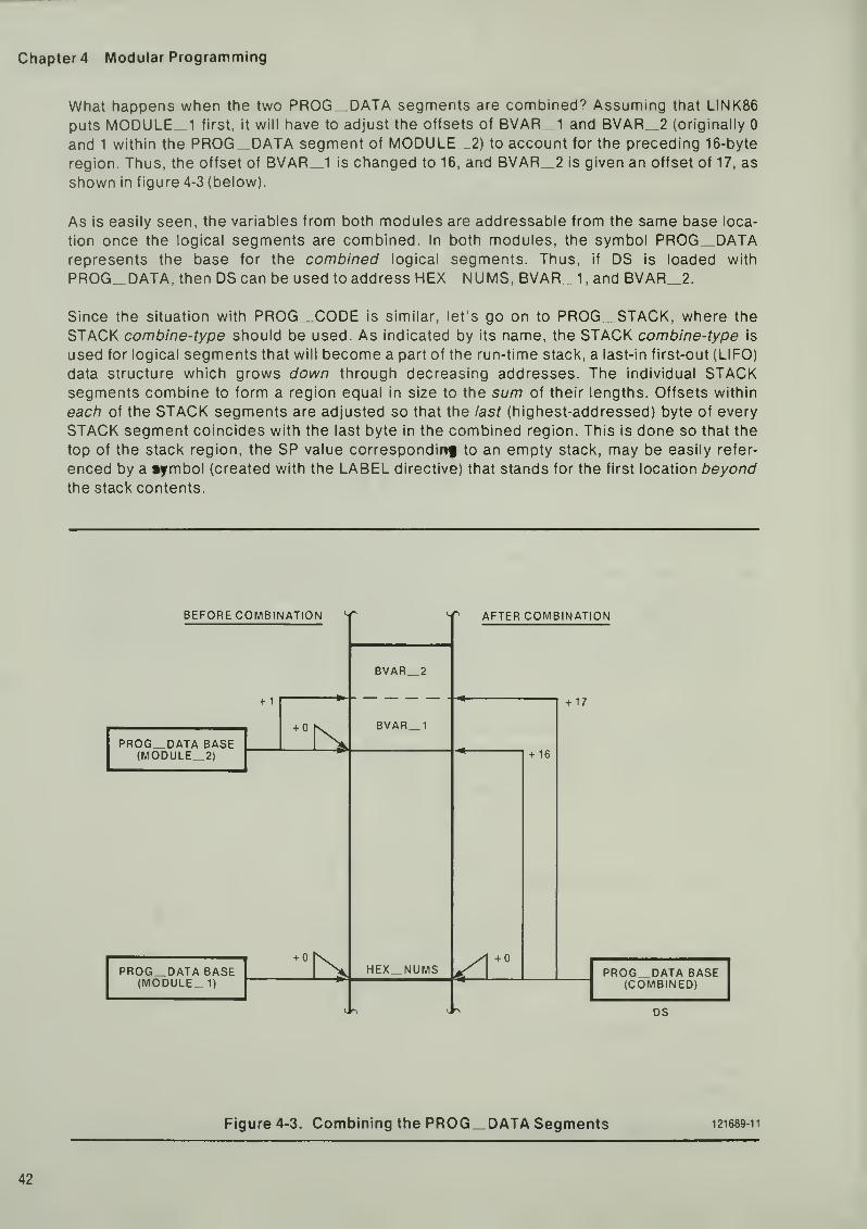
er4 Modular Programming
What happens when the two PROG DATA segments are combined? Assuming that LINK86
puts MODULE 1 first, it will have to adjust the offsets of BVAR 1 and BVAR 2 (originally 0
and 1 within the PROG DATA segment of M0DULE_2) to account for the preceding 16-byte
region. Thus, the offset of BVAR_1 is changed to 16, and BVAR_2 is given an offset of 17, as
shown in figure 4-3 (below).
As is easily seen, the variables from both modules are addressable from the same base loca-
tion once the logical segments are combined. In both modules, the symbol PROG„DATArepresents the base for the combined logical segments. Thus, if DS is loaded with
PROG_DATA, then DS can be used to address HEX_NUMS, BVAR_1, and BVAR_2.
Since the situation with PROG_CODE is similar, let's go on to PROG_STACK, where the
STACK combine-type should be used. As indicated by its name, the STACK combine-type is
used for logical segments that will become a part of the run-time stack, a last-in first-out (LIFO)
data structure which grows down through decreasing addresses. The individual STACKsegments combine to form a region equal in size to the sum of their lengths. Offsets within
eacti of the STACK segments are adjusted so that the last (highest-addressed) byte of every
STACK segment coincides with the last byte in the combined region. This is done so that the
top of the stack region, the SP value correspondinf to an empty stack, may be easily refer-
enced by a mbol (created with the LABEL directive) that stands for the first location beyondthe stack contents.
BEFORE COMBINATION S
+ 1
PROG_DATA BASE(M0DULE_2)
PROG„DATA BASE(MODULE 1)
+ 0
BVAR 2
BVAR_1
1EX_NUMS
AFTER COMBINATION
+ 16
+ 17
PROG DATA BASE(COMBINED)
DS
Figure 4-3. Combining the PROG DATA Segments 121689-11

An Introduction to ASM86
Assume that M0DULE__1 defines a STACK segment 24 words in length and uses the symbolSTK_TOP to indicate the top of the stack region. The PROG_STACK segment would be
coded as follows:
(in M0DULE_1)
PROG_STACK SEGMENT STACK
DW 24 DUP (?)
STK_TOP LABEL WORD
PROG_STACK ENDS
Now suppose that MODULE 2 requires that 16 words be added to the stack. If the symbolT_0_S is used to indicate the top of the stack region in this module, then the PROG_STACKsegment would be coded as shown below:
(in MODULE 2)
PROG STACK SEGMENT STACK
T 0 S
DW
LABEL16 DUP
WORD
(?)
PROG_STACK ENDS
When combined, these two STACK segments will form a region 40 words in length, and the off-
sets of STK_TOP and T^O^S will both be adjusted so that they refer to the first location
beyond the stack region. The resulting program stack is shown in the following diagram:
BEFORE COMBINATION
+ 32T_0_S
PROG STACK BASE(M0DULE_2)
+ 48STK__TOP
PROG_STACK BASE(MODULE^I)
AFTER COMBINATION
+ 80
STK_TOPT_0_S
PROG STACK BASE(COMBINED)
SS
Figure 4-4. Combining the PROG STACK Segments 121689-12
43

er4 Modular Programming
"[he Align-Type Attribute
The align-type attribute specifies the boundary on which a logical segment must be located.
The PARA align-type indicates that the logical segment must start on a paragraph boundary
(that is, at an address divisible by 16). Since this is the default, paragraph alignment will be
assumed if no align-type is explicitly specified. Other align-type options are WORD, which
specifies that the segment should begin at an even address, and BYTE, which indicates that
the segment may begin at any address. The BYTE align-type ensures that no gaps will occur
between logical segments. However, since word-alignment of variables is needed for fast
memory access by the 8086, the BYTE align-type should not be used for data regions in 8086
programs.
The Class-Name Attribute
If a class-name is given to a logical segment, it will be used by the locator (LOC86) in collecting
together all regions with identical class-names. For example, suppose you are writing a pro-
gram composed of code, constants, data, and a stack region, where each region is made up of
a combination of logical segments named PROG__CODE, PROG_CONST, PROG_DATA, and
PROG_„STACK, respectively. If you want to place the code and constants in ROfvl, you can
indicate that the PROG_CODE and PROG^CONST regions belong next to each other by
assigning these segments a common class-name , such as 'ROM^^REGION'. Similarly, you
can collect the PROG_DATA and PROG_STACK regions by assigning these segments the
same class-name , such as 'RAM_REGION'.
Notice that the class-name merely indicates that certain (already combined) regions are to be
placed next to each other in physical memory. Unlike the combine-type , the class-name doesnot force regions to be addressable from a common segment register value.
GROUPS
Suppose you do want dissimilar regions to be addressable from the same segment register
value. For instance, your data and stack regions may be small enough to fit into the samephysical segment. If they could be combined so that they would share a common base loca-
tion, then you could load SS and DS with identical values, and use only offsets from this com-mon base as pointers to variables and items in the stack. This combination of distinct program
regions is accomplished by using groups.
A group is simply a set of program regions combined so that they share a common base loca-
tion. The individual regions, such as PROG__DATA and PROG_ STACK, are contiguous within
the group. In effect, a group is a "combination of combinations," since a group is made up of
individual regions which themselves are made up of individual logical segments.
The GROUP statement is used to tell the assembler that two or more regions are to be com-bined. This directive has the following syntax:
Group Statement
grpname GROUP segname[ ,segname]...
The grpname is the name of the group. The segnames refer to combined logical segments that
are to be further combined into a group.

An Introduction to ASM86
A simple example should make the concept of groups clear. Suppose your program uses three
distinct data regions: read-only data in the PROG_CONST segments (combine-type PUBLIC),
read-write data in the PROG_DATA segments (combine-type PUBLIC), and a stack composedof PROG_STACK segments (combine-type STACK). Let's assume further that all three
regions will fit in one 64K physical segment.
If no groups are used, then the PROG_CONST, PROG DATA, and PROG_STACK regions
will each have a unique base. As far as data access is concerned, this may not be a big
problem; you could use DS to access PROG^DATA, SS for PROG^STACK, and ES for
PROG_CONST. (See figure 4-5, below.) However, if you want to store the address of a variable
(or pass the address to a procedure), you will have to use two words, since both the base andoffset part of the address need to be specified. (Note: In this looser sense, variable refers to a
unit of program data, named or unnamed, which could be in a data or stack region.)
Now, assume that the PROG^CONST, PROG DATA, and PROG_STACK regions share a
common base. (Refer to figure 4-6, next page.) This simplifies things in two ways: (1) you can
load DS and SS with this base value and use any of the available addressing modes (with the
default choices of segment register) to access all three regions, and (2) you can now use just
tlie offset of a variable to indicate its address, with the understanding that the base part is
always the value in SS and DS. This can be done if the PROG__CONST, PROG_DATA, and
PROG_STACK regions are combined into a group:
DATA_GROUP GROUP PROG_CONST, PROG_DATA, PROG_STACK
Recall that, when segments with the same name are combined, the segname is used to refer
to the base of the combined segments. Similarly, the grpname is used to refer to the base
common to all the regions in a group. Notice that the group base and the base for a segment
within a group are generally not ttie same. When groups are used, the segment registers
should be initialized using grpnames, not segnames. The grpnames should also be used in
the ASSUME statements for segment registers that will hold the base for a group.
SS
DS
ES
PROG_STACK
PROG DATA
PROG_CONST
121689-13
Figure 4-5. The Three Distinct Data Regions: PROG„CONST, PROG^DATA, and
PROG STACK
45

Chapter 4 Modular Programming
Because they refer to different base locations, the offset of a variable or label from its segment
and the offset from its group are also different. The OFFSET operator, introduced in Chapter 2,
always returns the offset of a variable or label from its segment. How/ever, when groups are
used, the offset from the group base is needed. This is specified by adding a group override to
the symbol referenced. The group override is a grpname, followed by a colon (:), in front of the
name of a variable or label. Thus, if VAR_1 is a variable in PROG_DATA, a segment in
DATA_ GROUP, then OFFSET VAR^I refers to the offset of VAR_1 from the PROG^DATAbase, while OFFSET DATA_GR0UP:VAR_1 refers to the offset of VAR^I from the
DATA_GROUPbase.
Figure 4-7, below, illustrates the differences between the group and segment bases for
DATA GROUP, which is made up of PROG CONST, PROG_DATA, and PROG STACK. The
figure also shows the offset of VAR_1 , a variable in PROG_DATA, from its segment and from
its group.
DS SS
PR0G_STACK
PROG_DATA
PROG_CONST
V DATA_GROUP
Figure 4-6. The Data Group, Composed of Three Regions: PROG CONST,PROG DATA, and PROG STACK 12 1689-14
PROG_STACK
OFFSET VAR_1
PROG DATA
PROG_CONST
VAR 1 OFFSETDATA GR0UP:VAR_1
DATA_GR0UP
Figure 4-7. Bases and Offsets in DATA GROUP 121689-15
46

An Introduction to ASM86
USING PROCEDURES
Programs written in a modular fashion tend to rely heavily on procedures (code sequencesexecuted out-of-line using the CALL instruction). A procedure is often designed to be a func-
tional block that produces a set of output data by performing a transformation on a well-defined
set of input data, or parameters . This section describes the ASM86 constructs used to define
procedures, and discusses parameter passing in general terms. This discussion is resumed in
the next chapter, where the PL/M-86 method of parameter passing is described.
Defining Procedures: The PROC/ENDP Statements
A procedure is a sequence of code containing one or more RET instructions designed to be
activated by a CALL instruction. The entry point of a procedure, the location where execution
begins for that procedure, is marked with a label. A CALL instruction using this label as its
operand will put a return address (the address of the instruction following the CALL instruc-
tion) on the stack, and transfer control to the location indicated. The code in the procedure will
continue to be executed until a RET instruction is encountered, at which time control returns
to the location specified by the return address on the stack.
The ASM86 PROC and ENDP directives are used to label the entry point of a procedure and to
indicate its extent. The PROC statement belongs at the beginning of a procedure, and the
ENDP statement goes at the end. The syntax of the PROC and ENDP statements is given
below:
The Procedure and End-Procedure Statements
procname PROC [NEAR|FAR]
(procedure body)
procname ENDP
The procname is a label used to indicate the procedure entry point. The type of this label,
NEAR or FAR, is indicated to the right of the keyword PROC. If no type is given, NEAR is
assumed. The type associated with aprocname is used by the assembler in determining which
CALL instruction to generate for the procedure. If FAR is indicated, the long form of the CALLinstruction will be used. In this case, both the OS and IP values are changed when control is
transferred, so a two-word return address (CS and IP) is pushed on the stack. For NEAR pro-
cedures, only IP gets changed, so the return address is a single word indicating an IP value.
Since there are two kinds of return addresses, there must be two kinds of RET instructions.
The RET for a FAR procedure restores both CS and IP using values from the stack, while the
RET used for NEAR procedures reloads only IP with the word stored on the stack. Both types
of return instruction are specified with the mnemonic RET. The assembler decides which RETinstruction to generate, based on the type associated with the surrounding PROC/ENDPstatements. Thus, the reason for indicating the extent of a procedure with the ENDP directive
is that the PROC/ENDP pair describes a domain where RET instructions of only one type are
generated.
47

er4 Modular Programming
The following is an example of a very simple procedure used to load the DX register with the
arithmetic mean of the values in AX and BX:
AVERAGE PROC NEAR
MOV DX, AX
ADD DX.BXRCR DX , 1 ; DX : = (AX + BX)/2
RET
AVERAGE ENDP
The above procedure begins with the MOV DX.AX instruction. This entry point is labelled with
the name AVERAGE. Since AVERAGE has type NEAR, a CALL AVERAGE elsewhere in the pro-
gram will generate the CALL instruction that changes IP only. Because the RET instruction is
inside a PROC/ENDP pair for a NEAR procedure, it will generate the RET instruction that
restores only IP.
So, the PROC/ENDP pair establishes a type (either NEAR or FAR) that is used in defining a
label for the procedure entry point and in determining which kind of RET instruction should be
generated between the PROC and ENDP statements. It is important to note that this is all the
PROC/ENDP directives do.
Unlike procedures written in high-level languages, procedures defined in ASM86 with
PROC/ENDP pairs do not have restricted scope. That is, the names defined within the
PROC/ENDP pair for either variables or labels may be referenced anywhere in the module, and
an instruction sequence just prior to a PROC statement will "fall into" (rather than "goaround") the procedure if executed. The best way to avoid accidental execution of procedure
code is to place your procedures above the code sequence from which they are called, and to
avoid nesting PROC/ENDP pairs.
Passing Parameters to Procedures
The values used as input data by a procedure are called parameters. A parameter may be a
numerical value, an address, or any number of other things. Parameters are supplied or
passed to procedures in many ways. One method of passing a parameter to a procedure is to
put its value in a variable in the data region, where it can then be retrieved by the procedure.
For example, a variable named PARf\/l 1 could be used to hold the first parameter for a pro-
cedure named COMPUTE DISTANCE. In this case. PARM 1 should be loaded with an
appropriate value prior to the call to COMPUTE DISTANCE, since the COMPUTE DISTANCEprocedure will use the value of PARM _1 in its calculations.
Another simple method of passing a parameter to a procedure is to place its value in a register.
In the example procedure above (named AVERAGE), two input parameters are passed in
registers, the values in AX and BX. Before calling the AVERAGE procedure to compute the
arithmetic mean of two values, the programmer must first write some code to load the two
values into the AX and BX registers.
Yet another parameter passing technique involves pushing the parameters onto the program's
run-time stack, where the procedure can then access them by popping from the stack or by
using an addressing mode involving BP. This is the PL/M-86 method of passing parameters,
which is discussed in the next chapter.

An Introduction to ASM86
Returning Values from Procedures
The effect of a procedure may be to alter a data structure, to return a value, or to do both. Aprocedure may use a variable or a register to return a value to its caller. A procedure that
returns a single value is considered to be a function. For example, the AVERAGE procedure
above is a function that returns the arithmetic mean of the values in AX and BX in the DXregister. The PL/M-86 conventions for values returned by functions vk/ill be covered in the next
chapter.
EXAMPLE PROGRAM
The example program for this chapter is made up of two separate assembly language source
modules, shown on the following two pages. This example is designed to illustrate the con-
cepts of public and external variables, segment combination, groups, and procedures. Thediscussion below will guide you through the example program and point out its most important
features.
First, look at the SEGMENT/ENDS and GROUP statements common to the two modules
EXAMPLE_4Aand EXAMPLE 4B:
DATA_GROUP GROUP PROG_DATA, PROG_STACK
PROG DATA SEGMENT WORD PUBLIC
PROG_DATA ENDS
PROG STACK SEGMENT WORD STACK
PROG_STACK ENDS
PROG CODE SEGMENT BYTE PUBLIC
PROG_CODE END5
Both modules have a word-aligned data segment (PROG DATA) with combine-type PUBLIC, a
word-aligned stack segment (PROG^STACK) with combine-type STACK, and a byte-aligned
code segment (PROG_CODE) with combine-type PUBLIC. The GROUP directive tells us that
the data and stack regions are further combined into a group called DATA_GROUP. This
means that the contents of PROG^DATA and PROG_STACK will be addressed using offsets
from a common base location.
Now look at the ASSUME statements, which are the same in both modules:
ASSUME CS : PROG_CODE , DS : DATA_GROUP
49

Chapter 4 Modular Programming
NAME EXAMPLE_4A
OATA_GROUP GROUP PROG_DATA, PROG_STACK
ASSUME CS:PROG_CODE, DS : DATA_GROUP
PROG_DATA SEGMENT WORD PUBLIC
NUMBER_AVERAGES DW 4 DUP (0) ; an array to hold averages of
; number pairs from other module,
EXTRN NUMBER_PAIRS:WORD, PA I R_COUNT : ABS
PROG DATA ENDS
PROG_STACK SEGMENT WORD STACK
DU 5 DUP C)STACK_TOP LABEL WORD
PROG STACK ENDS
PROG_CODE SEGMENT BYTE PUBLIC
EXTRN AVERAGE:NEAR
START
:
AVG
MOV AX , DATA_GROUPMOV DS , AX
MOV SS , AX
MOV SP, OFFSET DATA_GROUP:STACK_MOV CX,PAIR_COUNTMOV SI,0MOV DI , SI
MOV AX,NUMBER_PAIRS[SI]MOV BX,NUMBER_PAIRS[SI+2]CALL AVERAGEMOV NUMBER_AVERAGES [DI ] , DX
ADD SI ,4
ADD DI , 2
LOOP AVG
HLT
ENDS
END START
Figure 4-8. Main Module for Example Program
50

An Introduction to ASM86
NAME EXAMPLE_4B
DATA_GROUP GROUP PROG_DATA, PROG_STACK
ASSUME CS : PROG_CODE , DS : DATA_GROUP
PROG_DATA SEGMENT WORD PUBLIC
NUMBER_PAIRS OW 100, 28 ; an array of four number pairs.DW 37,1121DW 511, 512
DW 15, 7
PAIR_COUNT EQU 4 ; a constant, the number of pairs.
PUBLIC NUMBER_PAIRS, PAIR_COUNT
PROG_DATA ENDS
PROG_STACK SEGMENT WORD STACK
DW 2DUP(') ; add two words to stack length.
PROG_STACK ENDS
PROG_CODE SEGMENT BYTE PUBLIC
PUBLIC AVERAGE
AVERAGE PROC NEAR
MOV DX,AXADD DX,BX
RCR DX,1 ;DX:=(AX+BX)/2.RET
AVERAGE ENDP
PR06_C0DE ENDS
END
Figure 4-9. Other Module for Example Program
51

er4 Modular Programming
Since the data region is in a group, DS will contain a pointer to the base of the group, not the
data region. Since variables are to be addressed as offsets from the group base, it would be
incorrect to tell the assembler ASSUME DS:PROG DATA. The code region is not included in
any group, so CS will point to the base of PROG CODE, as indicated by ASSUMECS:PROG CODE.
The initialization code in the main module. EXAMPLE _ 4A, shows that both DS and SS will hold
the base of DATA GROUP, the group containing the data and stack regions:
START: MOV AX , DATA_GROUPMOV DS,AX
MOV SS,AXMOV SP, OFFSET D AT A_G ROU P : S T A C K_TO
P
Notice the group override used in the line initializing SP. Since SS contains the base for
DATA_GROUP, SP must be initialized with the offset of the top of the staci< region relative to
the group base, expressed as OFFSET DATA __GROUP:STACK_TOP. It would be incorrect to
initialize SP with the instruction MOV SP,OFFSET STACK__TOP (i.e., with no group override),
since OFFSET STACK_TOP refers to an offset from the base of the stack region,
PROG^STACK, not from the group base.
Thus far, the discussion has been concerned with the framework of the example program, its
structure in terms of logical segments and groups. Let's go on to the code and data that makeup the "working" part of the program.
Look first at the contents of PROG_DATA in EXAMPLE_4B:
NUMBER PAIRS
PAIR COUNT
DW
DU
DW
DW
EQU
100, 28
37,1121511, 512
15. 7
an array of four number pairs
a constant, the number of pairs
PUBLIC NUMBER_PAIRS,PAIR_COUNT
The variable NUMBER ^PAIRS refers to the first of eight words that will be treated by the pro-
gram as four pairs of numbers. The symbol PAIR_COUNT, defined with an EQU statement, is
a constant (a number with a name). Since both of these symbols need to be referenced outside
the EXAMPLE_4B module, they are made PUBLIC.
Now look inside the PROG_DATA segment in EXAMPLE_4A:
NUMBER_AVERAGES DW A DUP (0) ; an array to hold averages of
; number pairs from other module.
EXTRN NUMBER_PAIRS :WORD , PAI R_COUNT : ABS
The EXTRN statement indicates that NUMBER PAIRS, a word variable, and PAIR COUNT, a
constant, are symbols from another module that will be referenced in this module. The place-
ment of this EXTRN statement is crucial: the fact that this EXTRN statement is seen inside the
SEGMENT/ENDS pair for PROG DATA tells the assembler that NUMBER PAIRS wasdefined inside another segment named PROG DATA that will be combined with this one. That
is, the assembler learns from this EXTRN statement that NUMBER PAIRS belongs to
PROG DATA. (Since constants like PAIR COUNT do not have base:offset addresses like
variables, they may be referenced in EXTRN statements anywhere in the module.)

An Introduction to ASM86
The NUMBER_AVERAGES array consists of four words. The function of the program is to find
the average of each of the number pairs (always rounded down) and store these averages in
the NUMBER_AVERAGES array. For example, the first number pair is 100,28; its average (64)
will be stored in the first word of the NUMBER„AVERAGES array.
The actual computation of the numerical averages is done using the AVERAGE procedure,
found in the PROG„CODE segment of the EXAMPLE_4B module;
PUBLIC AVERAGE
AVERAGE PROC NEAR
MOV DX,AXADD DX,BX
RCR DX,1 ; DX := (AX + BX)/2.RET
AVERAGE ENDP
This is a NEAR procedure, as indicated by the PROC statement. This means that only IP will be
changed when a CALL AVERAGE is executed, so only an IP value will be stored on the stack as
a return address. The assembler will generate the proper RET instruction (which restores only
IP) since the RET mnemonic is seen between the PROC and ENDP statements for a NEAR pro-
cedure. Notice that AVERAGE, too, is a PUBLIC symbol, to be referenced outside the module
in which it is defined.
Returning to the EXAMPLE__4A module, we see the following statement in the PROG_CODEsegment:
EXTRN AVERAGE:NEAR
This statement says that AVERAGE is a NEAR label (in this case, a procedure entry point)
defined in another module. Once again, the placement of the EXTRN statement is crucial.
Because the EXTRN statement for AVERAGE is seen inside the SEGMENT/ENDS pair for
PROG_CODE, the assembler knows that AVERAGE belongs to the PROG_CODE segment.
All we have left to consider is the mainline code for this program, found in the PROG_CODEsegment for EXAMPLE^4A:
MOV CX, PAIR_COUNTMOV SI ,0
MOV DI , SI
MOV AX,NUMBER_PAIRS[SI]MOV BX,NUMBER_PAIRS[SI+2]CALL AVERAGEMOV NUMBER_AVERAGES [DI ] , DX
ADD SI ,4
ADD DI , 2
LOOP AVG
HLT
In this code, the CX register is used as a loop counter, and is initialized with the constant
PAIR_COUNT. The SI and DI registers, both initialized to zero, are used for indexing. SI holds
the offset of a particular number pair in NUMBER PAIRS, so it is advanced by 4 each time
through the loop. The expression NUMBER_PAiRS[SI] refers to the first of a pair of numbers;
53

er4 Modular Programming
the second number in the pair is referenced by NUMBER PAIRS[SI + 2). Dl is the offset into
the NUMBER AVERAGES array. Since each of the averages requires a word of storage, Dl is
adjusted by 2 each time through the loop.
An important feature of this code is the parameter passing. Before the AVERAGE procedure is
called, the AX and BX registers must each be loaded with a value to be used by the AVERAGEprocedure in its calculation. In other words, AVERAGE takes two parameters, two numbers to
be averaged, that are passed in the AX and BX registers. The AVERAGE procedure is a func-
tion, which returns the average of the two numbers in the DX register. After the AVERAGEprocedure is called for a pair of numbers, their average, in DX, is stored into the
NUMBER_AVERAGES array.
This ends the discussion of the example program for this chapter. By going to two modulesand employing a procedure to do some of the work, we have arrived at an example program of
realistic complexity. We can now go on to see how the concepts introduced in this chapter are
used in designing assembly language modules to work with modules written in PL/M-86, a
high-level language.
CHAPTER SUMMARY
An ASM86 program can be modular in two different senses: it can be composed of several
source files, and it can be designed around functional blocks implemented as procedures.
Breaking a program up into separate source modules produces a need for inter-module
references and methods of combining logical segments. The PUBLIC and EXTRN directives
allow symbols in one module to be referenced in another module. The combine-type attribute
given to a segment describes how it will be combined with other segments with the samename. Segments may be further combined into groups. These combinations are a means of
optimizing a program by making more and more of it accessible from the same base location.
Procedures are defined using the PROC and ENDP statements. These statements define a
label for the entry point of a procedure, and describe a domain where RET instructions of only
one type are generated. The values supplied to a procedure are called parameters; these maybe passed from the caller to the procedure in a variety of ways. In the next chapter, the
PL/M-86 method of parameter passing will be explored.

CHAPTERSCOMBINING ASM86 AND PL/M-86 MODULES
This chapter applies the modular programming concepts introduced in the previous chapter to
the special case of a program written partly in assembly language and partly in PL/M-86 (a
high-level language). First the PL/M procedural interface is discussed in general terms. This is
followed by an analysis of the PL/M SMALL "model of computation," one of the ways in which
segments can be combined and groups formed for PL/M code. The example program for this
chapter then illustrates the interface between a PL/M SMALL module and an assembly
language module. The chapter concludes with an overview of the other PL/M-86 models of
computation, highlighting their important features.
Although the PL/M theme runs throughout this chapter, much of the material can be valuable
even if you are not interested in writing PL/M-86 modules. Since the PL/M LARGE model is
used by FORTRAN-86 and PASCAL-86, this chapter can also be helpful if you are using these
programming languages. In addition, many of the concepts presented in this chapter will be of
interest even to the assembly language "purist." For example, you may decide to use the
PL/M procedural interface even if your entire program is written in assembly language.
The focus of this chapter is on writing assembly language modules to work with modules
written in PL/M-86. However, for the sake of illustration, a small amount of PL/M code is
shown. This chapter assumes that you are familiar with the PL/M language; no instruction in
writing PL/M code is given. Refer to the PL/M-86 Programming Manual or the PL/M-86 User's
Guide for 8086-Based Systems for information about this language.
THE PL/M-86 PROCEDURAL INTERFACE
When you write assembly language procedures to be called by PL/M code, and when you call
PL/M procedures from assembly language, you need to conform to the procedural interface
conventions used by PL/M. Simply put, the assembly language code which talks to PL/M codemust behave like PL/M code; it must do what PL/M expects it to do. The next few sections
discuss the PL/M-86 procedural interface in general terms. Later, a case study of PL/M SMALLwill show how these rules apply in a particular model of computation.
The PL/M Method of Passing Parameters
In PL/M code, all parameters for procedures are passed on the run-time stack. Bytes and
words are both passed as words pushed onto the stack. In the case of a byte parameter, the
value passed occupies the low-order byte of the word pushed onto the stack; the high-order
byte of this word is undefined. Pointer parameters (addresses of variables and labels) are also
pushed onto the stack. Short pointers (offsets from fixed segment register values) are passed
as words on the stack, while long pointers (complete base:offset addresses) are passed as
two words, with the base part being pushed first, followed by the offset part.

er 5 Combining ASM86 and PL/M-86 Modules
The parameters are pushed onto the stack in the order that they are seen in the PL/M CALLstatement. Because the parameters are pushed onto the stack before the CALL instruction is
executed, they are located above the return address, which is also stored on the stack.
As an example, suppose P is a procedure that accepts three parameters in the following order:
a word value, a byte value, and a long pointer value. If you assume that the PL/M-86 compiler
uses the long form of the CALL instruction for calls to P, then the statement CALLP(WVAL,BVAL,PVAL); will cause the stack to be set up as shown in figure 5-1 below. (Note:
This is not an example of the PL/M SMALL model of computation.)
Retrieving Parameters from the Stack
A program written in assembly language and called from PL/M may access its parameters on
the stack in either of two ways. One technique is to pop each of the parameters off the stack
and into either a register or a local variable. To do this, you must first pop the return address
off the stack into a place where it can be saved, then restore the return address by pushing it
back onto the stack after the parameters have been retrieved. With this method, a "normal"
RET instruction (with no operand) should be used, since the parameters will already have been
removed from the stack when the RET is executed.
As an example of this technique, suppose that the procedure P, mentioned above, is coded in
assembly language and called from PL/M. The following sequence of code saves the return
address in the SI and Dl registers, then restores this address to the stack once the parameters
have been removed. The parameter WVAL is popped into CX, the word containing BVAL is
popped into AX (BVAL is in AL), and the PVAL parameter is popped into a double-word variable
called PVAI TEMP.
WVAL
BVAL
PVAL (base part)
PVAL (offset part)
RETURN ADDRESS (CS)
RETURN ADDRESS (IP)
Figure 5-1 . State of the Stack Following CALL P(WVAL, BVAL, PVAL); 121689 16

An Introduction to ASM86
(in the data region)
PVAL_TEMP DD 0
(in the code region)
PROC FAR
p n p 0 1 odvc reLurnPOP DI add ress .
POP WORD PTR PVAL..TEMP PVAL_TEMP getsPOP WORD PTR pval|_TEMP + 2 ; pointer pa name t e r
.
POP AX AL gets byte parameterPOP CX CX gets word parameterPUSH DI Restore returnPUSH SI address.
RET/ Use a ' norma L ' RET
.
P ENDP
Another method of accessing parameters passed on the run-time stack is to address themusing a BP-relative addressing mode (recall that addresses involving BP use SS, the stack
base, as the default segment register). This is the technique used by PL/M code. The idea
behind this method of accessing parameters is to establish SS:BP as a pointer to the begin-
ning of the data structure on the stack containing the parameters, and then address the
parametersjjsing offsets from BP.
Since PL/M procedures make heavy use of the BP register, assembly language code used
with PL/M must preserve the value of BP. When parameters are popped off the stack, BP maybe preserved by simply not using this register. However, since the "BP method" requires that
BP be loaded with a new value, the contents of BP must first be saved. An easy way to save
BP—again, the method used by PL/M— is to first push its value, thereby allowing you to safely
load it with a new value, with the understanding that its old value must be restored with a pop
before the procedure returns to its caller.
Once BP has been pushed, it should be loaded with the current stack pointer, the value in SP,
so that offsets from BP can be used to address the parameters on the stack. It is very important
to note that the last parameter pushed will be addressed using the smallest offset from BP,
and that this offset will be greater than zero, since the parameter region is behind the saved
value of BP and the return address. (To be specific, the last word pushed on the stack as a
parameter will be at offset [BP + 4] for a NEAR procedure and at offset [BP-i-6] for a FARprocedure.)
When a procedure uses BP-relative addressing modes to access its parameters, they remain
on the stack. These parameters must be removed from the stack upon returning to the caller.
To do this, you use a special RET instruction, which allows you to specify (as an operand) a
value to be added to SP during the return. Note that this value is the number of bytes in the
parameter region, and does not include the word used to save BP (since it is popped prior to
the return) or the return address (since it is popped as part of the RET instruction).
57

Chapter 5 Combining ASM86 and PL/M-86 Modules
Again, consider the procedure P described above. Suppose P uses the BP method of
accessing parameters instead of the "pop method." The prologue for P (its first couple
instructions) should save BP with a push, then load BP with the current stack pointer. Oncethis is done, BP-relative addressing can be used to access the parameters. Figure 5-2, below,
shows the state of the stack after this procedure prologue has been executed.
The code fragment that follows shows how BP-relative addressing is used in the procedure P.
The prologue instructions, which save BP and then set it up for parameter addressing, as well
as the epilogue instructions, which restore BP and remove the parameters when returning, are
shown. Three additional instructions show a possible use of the parameters on the stack.
P PROC FAR
PUSH BP
MOV BP.SPSave caller's BP value.Point BP to stack f r ame
MOV
LES
ADD
AL, [BP+1 0]
BX, [BP+6]
CX , [BP+1 2]
Load AL with byte parameter.Load ES-:BX with long address.Add word parameter to CX value,
POP
RET
ENOP
BP
8
Restore old BP value.Remove parameters (8 bytes)when returning to caller.
WVAL
BVAL
PVAL (base part)
PVAL (offset part)
RETURN ADDRESS(CS)
RETURN ADDRESS (IP)
OLD BP
15
BP + 12
BP + 10
BP + 6
BP SP
Figure 5-2. State of the Stack Inside P After PUSH BP and MOV BP,SP 121689-17
58

An Introduction to ASM86
Choosing a Method to Access Parameters
When you are writing an assembly language procedure to be called from PL/M, you are faced
with the choice between the pop method and BP method of accessing parameters. Which is
best, which method should you choose?
The method you choose for accessing parameters will depend on the nature of the procedure
you are writing. The pop method can be an effective optimization when all parameters are
popped into registers, since accessing registers is faster than accessing memory. For this
reason, it usually makes sense to consider the pop method first for short procedures with few
parameters.
There are many factors that can make the pop method ineffective. If a procedure has manyparameters, the overhead for the pop method (the sequence of POP instructions) can nullify
the advantages to be gained from register accessing. Since some of the registers get used up
in holding parameters, the pop method should not be used when register space is at a
premium, as in a procedure which does extensive calculations on temporary values held in the
registers. A big advantage of the BP method over the pop method is that the parameter values
may be left unaltered and thus may be referenced many times in the procedure. The pop
method works best when each parameter value needs to be referenced only once and then
either altered by a calculation or discarded.
Returning Values from Functions
A function is a procedure that returns a single value to its caller. By convention, PL/M-86 func-
tions return values in registers. Word and integer values are returned in AX, and byte values
are returned in AL. Short pointers (offsets) are returned in BX, even though they are word-
length values, since an offset value in BX is directly usable for addressing. For a similar
reason, long pointers are returned with the base part in ES and the offset part in BX.
When writing functions in assembly language to be called by PL/M code, you must observe
these conventions. Also, when you call a PL/M function, you can use these rules to determine
where values will be returned.
Register Conventions
PL/M-86 code expects a procedure (or function) to preserve the values of BP, SS, and DS. That
is, a procedure is expected to restore the caller's stack frame and data segment before return-
ing. Upon return, SP should be adjusted so that all parameters are removed from the stack. IP
is always restored by the RET instruction, and in cases where CS is not reset by the RET
instruction, its value will be unchanged by the CALL, so (in correct code) restoration of CS and
IP is automatic. Thus, the list of registers to be preserved by a procedure or function is: SP,
BP, IP, CS, DS, SS.
The other registers may be used and not restored— they are volatile . Except when a function is
returning a value, PL/M assumes that the contents of the AX, BX, CX, DX, SI, Dl, ES, and flags
registers are unreliable upon return from a procedure.
When you write an assembly language procedure to be called from PL/M code, you must
ensure that the appropriate registers are preserved. Perhaps even more importantly, you must
realize that calling a PL/M procedure from assembly language destroys the AX, BX, CX, DX, SI,
Dl, and ES registers. Be careful not to get caught assuming that these registers are still
reliable after calling a PL/M procedure.
59

er 5 Combining ASM86 and PL/M-86 Modules
MODELS OF COMPUTATION
As seen in the previous chapter, there is a variety of ways in which segments can be combined
and groups formed using ASM86 directives. A rule which says how segments are to be com-
bined and possibly put into groups is called a model of computation . PL/M-86 offers several
models of computation, chosen by a compile-time control. The PL/M model of computation
you choose will determine what you must put in your assembly language SEGMENT and
GROUP statements. The model will also affect the particulars of the procedural interface— for
example, whether long (base:offset) or short (offset) pointers should be passed as
parameters.
The following discussion is a detailed analysis of one of these models, PL/M SMALL. Once
you understand one of the models, the others should be easy to understand. An overview of
the other PL/M models of computation is given later in the chapter.
CASE STUDY: PL/M SMALL
The PL/M SMALL model is easily summarized: code in one physical segment, data and stack
in another. The SMALL model, then, is used for programs that require no more than 64K of
code and 64K of combined data and stack. The advantage of the SMALL model is that all
pointers are merely offsets. OS is fixed, so a JMP or CALL needs only to change IP. DS and SSare fixed— to the same value— so only an offset is needed to specify the address of a variable
or item on the stack. As a result of these optimizations, the SMALL model offers the tightest
code and fastest instructions of the PL/M models.
CGROUPand DGROUP
The code for a PL/M SMALL program goes into a segment appropriately named CODE. As you
might have guessed, the data belongs in the DATA segment, and the stack in the STACK seg-
ment. Two other segments, CONST and MEMORY are also available to hold data values. Since
these segments are seldom used in assembly language modules, they will be left out of mostof the discussion to follow.
The SMALL program is split into two groups, reflecting the rule, "Code in one physical seg-
ment, data and stack in another." The CODE segment is the only member of CGROUP. a group
with base in CS. The DATA, STACK, CONST, and MEMORY segments are all members of
DGROUP, which has its base in both DS and SS. Figure 5-3 (opposite page) shows the memorylayout for the SMALL case program.
Following the figure is a template for an assembly language module conforming to the PL/MSMALL model of computation, the framework in which a SMALL case program is built. Thetemplate shows the SEGMENT statements for the CODE, DATA, and STACK segments, as well
as the GROUP and ASSUME statements, exactly as they should appear in the module. Thesegment align-type attributes may differ from the PARA default used below, but the combine-
type and class-name attributes must be as shown. (Note: For simplicity, two other segments,
CONST and MEMORY, have been omitted from this template. See Appendix A for a completeSMALL case template.)

An Introduction to ASM86
DGROUP J(MAXIMUM 64K) A
CGROUP J(MAXIMUM 64K) A
MEMORY
STACK
DATA
CONST
CODE
DS = SS= DGROUP
CS=CGROUP
Figure 5-3. IVIemory Layout for a PL/M SMALL Program 121689-18
CGROUP GROUP CODE
DGROUP GROUP DATA, STACK
ASSUME CS:C6R0UP, DS:DGROUP, SS:DGROUP
DATA SEGMENT PUBLIC 'DATA'
DATA ENDS
STACK SEGMENT STACK 'STACK'
STACK ENDS
CODE SEGMENT PUBLIC 'CODE'
CODE ENDS
Figure 5-4. A Template for a SMALL Case Program
Register Initialization
If the main module of your SMALL model program is written in assembly language, it is impor-
tant that you correctly initialize the segment registers and SR. As indicated above, CS should
point to CGROUP. This means that the END statement in the main module must use a label in
the CODE segment (which is in CGROUP) for the start address. DS and SS should both hold the
DGROUP base. SP should be set to the offset of the top of the stack region relative to
DGROUP. The following program fragment shows how code in an assembly language main
module sets up the registers for a SMALL case program. In this fragment it is assumed that
STK_TOP is a symbol used to indicate the top of the stack region.
61


Chapter 5 Combining ASM86 and PL/M-86 Modules
NAME EXAMPLE_5B
CGROUP GROUP CODE
DGROUP GROUP DATA, STACK
ASSUME CS:CGROUP, DS:DGROUP
DATA_TABLE SEGMENT
DB 256 DUP (8 DUP (0)) ; Room for 256 eight-byte entries.
DATA TABLE ENDS
DATA SEGMENT PUBLIC 'DATA*
NEXT_INDEX DB 0 ; Index of next entry to be entered.EXTRN ENTRY_BUFFER:BYTE
DATA ENDS
STACK SEGMENT STACK 'STACK
DW 4 DUP (?)
STACK ENDS
CODE SEGMENT PUBLIC 'CODE-
PUBLIC CREATE_ENTRY , LOOKUP_ENTRY
CREATE_ENTRY PROC NEAR
; Parameters:
; WVAL, a word value, at location [BP+6]
; Offset of a six-byte string, at location [BP+4]
; Function:
; Makes a new entry in DATA_TABLE, with WVAL in first word and
; string in next six bytes. Returns index for new entry in AL.
PUSH BP
MOV BP,SPMOV AX,DATA_TABLEMOV ES,AX ; ES holds base for DATA_TABLE.MOV AL,NEXT_INOEXMOV AH,0MOV DI.AX
Figure 5-6. ASM86 IVIodule Containing Support Procedures and Data Table Segment
64

An Introduction to ASM86
; Set DI to 8 * NEXT_INDEX,; so ES:DI addresses next entry.
; Store WVAL into entry.
; Point ES:DI to string portion of entry.; OS:SI addresses string to go in entry.
; String is 3 words (6 bytes) long.
; Use string move to put string in entry.; Update index for next entry.
; AL reflects index for entry stored'
CREATE_ENTRY ENDP
LOOKUP_ENTRY PROC NEAR
; Parameter is an entry index, popped into BL.
; Procedure moves entry with given index into ENTRY_BUFFER array.
RETRIEVE
POP AX Save return address.POP BX BL := index parameter.PUSH AX Restore return address.MOV AX , DATA TABLEMOV ES,AX ES holds base for DATA_TABLE.MOV BH , 0
SHL BX , 1
SHL BX , 1
SHL BX,1 ES:BX points at entry to retrieveMOV DI ,0 Offset for first word in entry.MOV CX,4 Entry is four words long.ENTRY :
; Move entry a word at a time into buffer in DGROUP.MOV AX,ES: [BX] [DI]
MOV WORD PTR E N T R Y_B U F F E R [ D I] , A
X
ADD DI,2LOOP RETRIEVE_ENTRYRET
LOOKUP_ENTRY ENDP
CODE ENDS
END
Figure 5-6. ASM86 Module Containing Support Procedures and Data Table Segment (Cont'd.)
Let's go through the assennbly language nnodule first, since this is the main area of emphasis.The first thing to notice is the frameworl< of the module. This module conforms to the SMALLmodel of computation, so CGROUP and DGROUP are defined and assumed into the OS and DSregisters, respectively. These groups contain the CODE, DATA, and STACK segments, which
will be combined with the CODE, DATA, and STACK segments created by the PL/M compiler
for the main module.
SHL DI,1
SHL 01,1SHL DI,1
MOV BX,[BP+6]MOV ES:[DI],BXADD DI,2MOV SI,[BP+4]MOV CX,3CLD
REP MOVSWINC NEXT_INDEXPOP BP
RET 4
65


Chapter 5 Combining ASM86 and PL/M-86 Modules
This procedure uses the pop method to access its single parameter. The first three instruc-
tions save the return address in AX, pop the parameter word into BX (the index goes into BL),
and then restore the return address to the stacl<:
POP AX ; Save return address.
POP BX ;BL:=index parameter.
PUSH AX ; Restore return address.
Again, ES is used to address the entry in DATA TABLE, so ES is loaded with the base for the
DATA_TABLE segment:
HOV AX , DATA_TABLE
MOV ES.AX ; ES holds base for DATA_TABLE.
The offset for the entry is eight times its index:
MOV BH,0
SHL BX,1
SHL BX,1
SHL BX,1 ; ES:BX points at entry to retrieve.
The entry will be moved a word at a time into ENTRY_BUFFER. The Dl register is used as the
offset of the word being moved, for both the source and the destination. Initially, then, Dl is
zero. The words are moved using a loop, where OX serves as loop counter. OX is initialized to
4, since four words need to be moved. The rest of the code in the LOOKUP_ENTRY procedure
is shown below:
MOV DI,0 ; Offset for first word in entry.
MOV CX,4 ;Entry is four words long.
RETRIEVE_ENTRY
:
; Move entry a word at a time into buffer in D6R0UP.MOV AX , ES : [BX] [Dl ]
MOV WORD PTR ENTRY_BUF FER [ D 1] , AX
ADD DI,2LOOP RETRIEVE_ENTRYRET
In the above code, notice how the rather complex address expressions (ES:[BX][DI) and WORDPTR ENTRY_BUFFER[DI]) allow a very tight loop, where only one offset value (Dl) needs to be
adjusted. In two lines, you can see why the discussion in Chapter 3 of addressing modes, seg-
ment overrides, and type overrides is so important!
The RET instruction in LOOKUP_ENTRY uses no operand, no value to be added to SP upon
return to the caller. The reason for this is that the parameter for LOOKUP„ENTRY was
removed from the stack at the beginning of the procedure, when it was popped into BX.
Now, let's move on to the main module for this program, coded in PL/M. The assembly
language support procedures are declared external with the following statements:
CREATE_ENTRY : PRO C E DUR E ( W V A L , S T R I N 6_PT R ) BYTE EXTERNAL;DECLARE WVAL WORD, STRING_PTR POINTER;
END CREATE_ENTRY
;
LOOKUP_ENTRY : P ROC E OUR E ( I N D EX ) EXTERNAL;DECLARE INDEX BYTE;
END LOOKUP_ENTRY;
68

An Introduction to ASM86
The data declarations define the eight-byte ENTRY BUFFER region (public, so that it can beused by the assembly language nnodule), a six-byte string, and a byte to hold an index value:
DECLARE ENTRY_BUFFER (8) BYTE PUBLIC-
DECLARE STRING1 (6) BYTE I N I T I A L ( ' E N T R Y 1 ') ,
ENTRY_INDEX BYTE;
The main program code for this example consists of two lines of PL/M:
ENTRY_INDEX = C R E AT E_E N T R Y (1 0 0 , 3 S T R I N G 1 )
;
CALL LOOKUP_ENTRY (ENTRY_INDEX)
;
The above lines illustrate the use of the assembly language support procedures. Since
CREATE_ENTRY is a function (it returns a value), it is called v^/ith an assignment statement.
This call produces a new entry in DATA_TABLE with value 100 and string 'ENTRY1'. The index
for the new entry is returned in the ENTRY^JNDEX variable (PL/M assigns AL to
ENTRY_iNDEX). The next line shows a call to LOOKUP_ENTRY, which moves the entry just
created into the ENTRY^BUFFER region.
The last thing to notice about the PL/M module is the control line at the top. By specifying
SSMALL you tell the compiler that you want the PL/M SMALL model of computation. Using this
information, the compiler will automatically create CGROUP and DGROUP, NEAR calls, etc. for
this module.
OTHER MODELS OF COMPUTATION
In addition to SMALL case, PL/M-86 offers three other models of computation called
COMPACT, MEDIUM, and LARGE. Each of these models allows either more code, more data,
or more code and data than the SMALL model, but at the price of slightly less efficiency. Thediscussion below is a brief summary of these other models of computation.
The COMPACT Model
The PL/M COMPACT model of computation differs only slightly from the SMALL model. TheCODE segment is still in CGROUP and the DATA and CONST segments are still in DGROUP.but the STACK and MEMORY segments stand alone, outside of any group. As a result, these
segments may occupy a full 64K bytes of memory.
Because variables on the stack have a different base from those in the data region, long
pointers (base:offset) are allowed with the COMPACT model. This means that the PL/MPOINTER data type is a double-word address, and that the PL/M @ operator refers to a long
address. Recall that long pointers passed as parameters occupy two words on the stack, with
the base part pushed first, followed by the offset part. Short pointers (offsets from DGROUP)are also allowed, and are associated with the WORD data type and the dot (.) operator.
With the introduction of long pointers, the PL/M code becomes capable of addressing data
anywhere in the physical memory space. For example, if an additional data segment (outside
of DGROUP) is created in an assembly language module, addresses of variables in this region
may be passed to PL/M procedures as parameters.
69

er 5 Combining ASM86 and PL/M-86 Modules
The MEDIUM Model
The PL/M MEDIUM model of computation is essentially another variation on the SMALL case.
In this model, the DGROUP is exactly the same as in SMALL case, containing the DATA,STACK, CONST, and MEMORY segments. There is no CGROUP, however: each module pro-
duces its own, non-combinable (i.e., not PUBLIC) code segment. Thus, the key feature of the
MEDIUM model is that it allows large amounts of program code.
Because each module produces its own code segment, inter-module calls use the long form of
the CALL instruction; that is, they change both OS and IP. This means that calls to assemblylanguage procedures will store a two-word return address on the stack, and that external PL/Mprocedures should be declared as type FAR in the ASM86 EXTRN statement.
In order to allow labels in different code segments to be referenced, the MEDIUM model also
allows long pointers. Again, the PL/M POINTER data type and (g operator are associated with
long addresses (baseioffset), and the WORD data type and dot (.) operator are used for offset
addressing.
The LARGE Model
The PL/M LARGE model, which is also used by PASCAL-86 and FORTRAN-86, allows for large
amounts of code and data. In this model, all code and data segments are non-combinable and
no groups are used. There is still only one STACK segment, however, with the STACKcombine-type.
Like the MEDIUM model, the LARGE model requires that inter-module calls use the long form
of the CALL instruction, which saves both CS and IP in the return address. Because data
references across modules refer to different base locations, all address parameters for inter-
module calls should be long pointers.
Since the data segments are not combined in LARGE case, each module has its own local data
region. This means that a procedure to be called from other modules must save the caller's DSvalue, set up DS so that its own local variables can be addressed, and then, before returning,
restore the caller's DS value. A public procedure can avoid this save and restore of DS only if it
uses no local variables, or if all the local variables it uses are on the stack, rather than in the
data region.
PROGRAM TEMPLATES
Appendix A contains program templates for each of the PL/M-86 models of computation.
These are shells for assembly language modules, showing the SEGMENT, GROUP (if
necessary), and ASSUME statements compatible with the various models. If you start with one
of these templates when writing an assembly language module to be used with PL/M, you will
have a ready-made frame in which you can immediately begin defining data and coding instruc-
tions. See Appendix A for details.
CHAPTER SUMMARY
With the PL/M-86 procedural interface, all parameters for procedures are passed on the run-
time stack. These parameters may be accessed by popping them off the stack or by address-
ing them using offsets from the BP register. Functions return values in registers: AX for words,

An Introduction to ASM86
AL for bytes, and BX or ES:BX for pointers. By convention, procedures used with PL/Mpreserve the SP, BP, IP, CS, DS, and SS registers: the AX. BX, CX, DX, SI. Dl, ES, and flags
registers, when not employed for returning values, are considered volatile.
PL/M-86 offers several different models of computation . methods of combining segments and
forming groups. The particular model used will determine the specifics of the procedural inter-
face, such as whether pointers are long or short and whether return addresses occupy one or
two words on the stack. The templates in Appendix A will help you get started writing
assembly language modules to conform to the PL/M models of computation.
71


CHAPTERSHELPFUL HINTS
In the previous chapters, sidelights were purposely avoided in order to keep a focus on the
core material being presented. This chapter serves as a catchall for some of the useful
programming ideas that were left out of the preceding discussion. The material in this
supplementary chapter draws heavily on the information already supplied and is presented in
a loosely-organized, topic-by-topic style.
ALIASES FOR VARIABLES
The 8086 and 8088 allow you to access the high and low bytes of the word-length AX, BX, CX,
and DX registers independently. In an analogous sense, you will find it quite useful to be able
to independently address the low and high bytes of a word variable, and the low and high
words of a double-word variable. This section shows how variable aliases can be used to
access the bytes in a word variable. The case of a double-word variable is very similar.
As was shown earlier, the type override operator can be used to access a byte in a word
variable. For example, MOV AH, BYTE PTR WVAR + I will load the AH register with the high
byte in the word variable WVAR. This construct is adequate for an occasional reference, but if
the individual bytes in WVAR are to be accessed often, it would be convenient to define simple
names for BYTE PTR WVAR and BYTE PTR WVAR + 1. One way of doing this is by using a pair
of equates, as shown below:
UVAR DW 0
LOW_BYTE EQU BYTE PTR WVAR
HIGH_BYTE EQU BYTE PTR WVAR+1
Now the symbols LOW_BYTE and HIGH_BYTE may be used to address the bytes in WVAR,as in MOV AH,HIGH„BYTE. These symbols are called aliases, since they are new names for
data units already allocated.
An even simpler technique for making two bytes addressable individually, and together as a
word, makes use of the LABEL statement:
WVAR LABEL WORD
LOW_BYTE DB 0
HIGH_BYTE DB 0
In this case, the data is allocated as two separate bytes, and WVAR is used as an alias for the
word composed of the two byte variables LOW_BYTE and HIGH„BYTE. Notice that the loca-
tion of the LABEL directive in the source file determines the segment and offset associated
with the variable (or label) being defined. WVAR is defined to be a variable with type WORD,but with the same segment and offset as LOW„BYTE.

Chapter 6 Helpful Hints
ALIASES FOR PARAMETERS ON THE STACK
The equate directive can also be used to create aliases for parameters passed to a procedure
on the run-time stack. For example, suppose A PROC is a NEAR procedure which uses the
BP method to access two parameters, a byte count and a word offset, passed on the stack.
Following the procedure prologue (PUSH BP/ MOV BP.SP), the two parameters may be
accessed using the symbols, COUNT_PARM and OFFSET^PARM, defined below:
COUNT_PARM EQU BYTE PTR [BP+6]
OFFSET_PARM EQU WORD PTR [BP+4]
By defining aliases, like COUNT_PARM and OFFSET_PARM, for parameters passed on the
stack, you create symbols that are both easy to use and easy to understand. Your code will be
a lot more readable if it contains self-documenting lines like MOV CL,COUNT_PARM instead
of mysterious lines like MOV CL,[BP + 6].
LONG CONDITIONAL JUMPS
The 8086/8088 conditional jumps (JC, JBE, JZ, ...) are two-byte instructions, where the first
byte is the opcode and the second indicates a signed number to be added to the instruction
pointer (IP) if the jump is taken. This signed offset byte reduces the size of the frequently-
occuring conditional jump instructions, but gives them a limited range -128 to +127 bytes. In
other words, the target label for a conditional jump must be within -128 to +127 bytes of the
instruction.
Usually, the restricted range of the conditional jump instructions is not a problem, but
occasionally you will need to do a long conditional jump to a label outside the -128 to +127
byte range. There are two techniques you can use to do this, which we can call the vectored-
jump and \hejump-around-jump methods.
With the vectored-jump, a conditional jump is taken to an intermediate target, a JMP instruc-
tion, which then transfers control to the desired location in the code. This method assumesthat there is a spot somewhere inside the -128 to +127 byte range of the conditional jumpwhere a JMP instruction may safely be placed, such as below another JMP instruction or just
following a RET instruction. In the following example, a vectored-jump is used to code a "jumpon zero" to TARGET, a label outside the -128 to +127 byte range of the JZ instruction:
TARGET :
JMP SOMEWHERE
GOTO_TARGET
:
JMP TARGET
JZ GOTO_TARGET
Figure6-1. Long Ji/mp on Zero to TARGET: Vectored-Jump Method
74

An Introduction to ASM86
The jump-around-jump technique also uses a JMP instruction to extend the range of the condi-
tional jump. However, in this case the JMP instruction immediately follows a conditional jumpwith reversed sense. This way, control flows normally—around the JMP instruction—when the
original condition is not met, and the JMP is taken when the original condition is met. Anadvantage of this technique is that you do not have to find a safe place for your JMP instruc-
tion, you create one. In the example below, the jump-around-jump method is used to again
code a "jump on zero" to TARGET, a label outside the range of the JZ instruction. (Notice the
JNZ!)
TARGET
:
JNZ CONTINUEJMP TARGET
CONTINUE:
Figure 6-2. Long Jty/np on Zero to TARGET: Jump-Around-Jump Method
The vectored-jump and jump-around-jump techniques do the same job, with the same numberof instruction bytes. How, then, do you know which to choose? The first consideration has
already been mentioned: if you cannot find a safe place to put a JMP instruction for the
vectored-jump method, then a jump-around-jump must be used. Assuming that such a place
exists, the only other consideration is one of instruction timing. The vectored-jump is just as
efficient as a regular conditional jump in the condition-not-met case, but adds time to the case
where the condition is satisfied. The jump-around-jump distributes added time more evenly
between the two cases. If you have a reason to prefer adding time to the condition-met cases
(for example, if they occur less frequently), then you should use the vectored-jump method. If
you don't want to treat either case preferentially, then the jump-around-jump should be
employed.
SHORT JUMPSThe 8086 and 8088 offer two different JMP instructions for accessing labels within the current
code segment. Both consist of a single-byte opcode, followed by a displacement field specify-
ing a value to be added to IP. The first, which can be called the NEAR JMP, has a word-length
displacement field, and can thus transfer control to any NEAR label. The other is called the
SHORT JMP, since it uses a sign-extended byte displacement and can only reach labels within
-128 to -1-127 of the current location. The SHORT JMP instruction is an optimization, since it
eliminates one byte of code each time it is used instead of the more general NEAR JMPinstruction.
When you code a jump to a NEAR label that precedes the JMP instruction in the source file,
the assembler will automatically generate a SHORT JMP, if it finds the label to be less than 129
bytes away. Thus, for backward jumps, the assembler does the code optimization for you. In
the following example, the JMP BACKWARD instruction will produce a two-byte SHORT JMP if
BACKWARD is inside the 128 byte range; otherwise, the three-byte NEAR JMP instruction will
be used.
BACKWARD:
JMP BACKWARD
75

Chapter 6 Helpful Hints
If you instead code a forward jump (to a label following the JfVIP instruction in the source file),
the assembler will not know the distance between the Jf\/IP and the target label. To guarantee
that the target will be reached, the assembler will always reserve space for the longer NEARJMP instruction. Thus, in the following code, JfVlP FORWARD will produce three bytes of
machine code, even if FORWARD is inside the range of the SHORT JMP.
JMP FORWARD
FORWARD
:
In order to optimize a forward jump, you must tell the assembler that the target label is in
range. If you estimate that the code between the forward jump and its target label is less than
128 bytes, you should use the SHORT operator in the JMP instruction, as shown in the examplebelow:
JMP SHORT FORWARD
FORWARD:
When the assembler sees the SHORT operator applied to a JMP target, it always tries to
generate the SHORT JMP instruction. If the label is found to be outside the 127 byte range of
this instruction, the assembler will issue an error message, saying that the label cannot be
reached. This error message tells you that your code size estimate was too low, and that the
SHORT JMP optimization is not possible in this case. To fix this error, you must edit your
source file to remove the SHORT operator from the JMP instruction.
Thus, the process of SHORT JMP optimization for forward jumps involves guesswork on your
part; it does not come automatically. Still, it is often very easy to see that a label is within the
range of the SHORT JMP, so the trial-and-error approach is seldom required. Keep the SHORToperator in mind, then, when you code your forward jumps.
USING A NUMBER FOR DIRECT OFFSET ADDRESSING
In the discussion of the direct offset addressing mode (Chapter 3), only variable accessing wasshown, as in MOV AX.VAR 1. What happens if you know the offset needed and want to
specify it explicitly? In this case, you need to be able to tell the assembler that a number is
being used, not as a constant value, but as an offset value. To do this, you use the type over-
ride operator to give a new type to the number.
For example, you may know that ES holds the base of a large data table and that you want to
load the AX register with the word at offset 8 from the start of the table. If you codeMOV AX,ES:8, you will get an error message, telling you that you cannot use the segment over-
ride operator with a number. In order to use 8 as the offset of a word variable, you need to
change its type from number to WORD, using the type override operator. Thus, the correct wayof coding the instruction to load AX with the word in memory at ES:8 is:
MOV AX,ES:WORD PTR 8
76
An Introduction to ASM86
A word of caution : when a number is used to specify an offset value, the assembler assumesnothing about the segment register intended to be used for the base part of the address. This
means that a segment override operator is always necessary in these cases. For example, if
you want to load the AX register with the word at offset 8 from DS, you must include a
DS-override in the instruction. MOV AX,DS:WORD PTR 8 is correct; MOV AX,WORD PTR 8 is
incorrect and will produce an error message.
ABSOLUTE CODE
All of the example code shown thus far has been relocatable . which means that it was not
assigned a particular memory address at assembly-time. Sometimes you need to be able to
specify exactly where your code will be located in physical memory. For example, you mayhave a program that initializes one or more of the interrupt vectors, which start at location zero.
Code assigned to a particular memory address is called absolute code and is produced by
using the AT combine-type for logical segments.
The construct AT expression is a combine-type which allows you to specify the start address
of a logical segment, and thus fix the location of its contents. The expression indicates a
paragrapti number, equal to the base value needed to access the segment.
To define a variable or label at a specific offset from the start of a segment, you use the ORGdirective to adjust the value of the location counter, a value used by the assembler to keep
track of the current offset within the segment. The ORG directive is specified as ORG expres-
sion , where the expression specifies the new location counter value. Thus, for example, ORG50 tells the assembler that the next variable or label defined should have offset 50 within the
current segment.
The following example shows how the AT combine-type and the ORG directive may be used to
define a double-word variable to access location 8 in physical memory, the address of the
interrupt 2 (NMl) vector. Notice that, since a LABEL statement is used instead of a DD, no
storage is allocated by this code.
ABSOLUTE_ZERO SEGMENT AT 0
ORG 8
INT1_VECT0R LABEL DWORD
ABSOLUTE_ZERO ENDS
CHAPTER SUMMARY
This chapter is intended to save you some time by teaching you a few useful programming
ideas that you might otherwise have to discover on your own. When you use aliases for
variables and procedure parameters, you make your code easier to write and more under-
standable. By cleverly coding your jump instructions, you can extend the range of the condi-
tional jump and save code with the SHORT JMP. Finally, as shown in the last two sections, you
can even specify addresses explicitly, if you know how to use the PTR, AT, and ORGconstructs.
77


CHAPTER?WHAT'S NEXT?
The focus of this manual is on teaching you the fundamentals of constructing ASM86 source
modules and providing you with the conceptual background you will need in order to write
ASM86 code. The emphasis throughout is on the basics, the information you will need in
getting started writing 8086/8088 assembly language code. This chapter briefly summarizessome of the areas not covered in this manual, but described in other ASM86 documentation.
Note : in this preview of coming attractions, the title of the ASM86 Language Reference Manualis abbreviated to Reference l^anual, and the term Operating Instructions refers to either the
8086/8087/8088 l^acro Assembler Operating Instructions or the MCS-86 Macro AssemblerOperating Instructions
.
8086/8088 INSTRUCTION SET
The main reason for writing an assembly language module is to specify each instruction to be
executed by the 8086 or 8088. This manual teaches you how to construct an ASM86 source file
and provides some basic information about instruction statements, while neglecting to tell you
about the instruction set you will be using in your assembly language modules. You should
refer to the Reference Manual for a complete description of the 8086/8088 instruction set.
8087 CODE
Some versions of the ASM86 assembler support code written for the 8087 Numeric Data Pro-
cessor, in addition to assembling code for the 8086 or 8088 Central Processing Unit. The
Reference Manual describes the instruction set for the 8087 and provides other information
you will need in order to write code for the NDP. Included in this information is a description of
how to define and access the additional data types supported by the 8087 (QWORD and TBYTE)
and how to reference the elements of the on-chip floating point stack.
EXPRESSIONS
ASM86 supports a large number of operators to be used" in forming assembly-time expres-
sions, and allows for some very complex combinations of operators and operands within
expressions. In this manual, only a few of these operators have been used, such as + and
OFFSET. The table below is provided to give you an idea of the variety of assembly-time
operators available. Refer to the Reference Manual for an explanation of how these operators
function and where they may be used.

er7 What's Next?
Table 7-1 . Partial List of Assembly-Time Operators
Arithmetic + ,-,*./, MOD. SHL, SHRLogical NOT, AND. OR. XORRelational EQ, NE, LT, LE. GT. GEAttribute-Returning TYPE, SEG, OFFSETData-Specific LENGTH, SIZE
Record-Specific WIDTH, MASK
STRUCTURES
The ASIV186 structure provides a convenient means of defining and accessing variables with
complex data types. The STRUC and ENDS statements are used to define a template for a data
structure composed of fundamental data units (bytes, v^/ords, etc.), and the name of this
template may then be used to allocate variables mth the newly-defined data type. The various
fields within such a variable are accessed using the special dot (.) operator. The following pro-
gram fragment shows an example of a structure template definition, a variable allocated using
the template, and the use of the dot operator in accessing one of the fields in the variable. For
more information about structures, see the Reference Manual.
(definition of structure template)
THREE_DIMENS IONS STRUCL DW ? ; This structure defines a new,
W DW ? ; three-word data type, with length,
H DW ?;
width, and height fields.THREE_DIMENSIONS ENDS
(allocation of variable using template)
BOX THREE_DIMENSIONS <1,2,3>
; Allocates a three-byte variable named BOX, with length = 1,
; width = 2, and height = 3.
(access to a field wittiin variable)
MOV AX, BOX. W ; Loads AX with the width field in BOX.
RECORDS
While structures help you deal with large composite data types, records are provided in ASM86to aid you in defining and accessing small, bit-encoded data types. As with structures, first a
record template is defined, assigning a name and bit count to each field within a byte or word;
then the name of the template may be used to allocate data. Special record-specific operators
assist you in accessing the fields within a bit-encoded variable. In the example code that
follows, a record template is defined and then used to allocate a bit-encoded byte variable.
Finally, the MASK operator is used to test the setting of one of the bit fields in the variable. For
a more detailed discussion of records, see the Reference Manual.
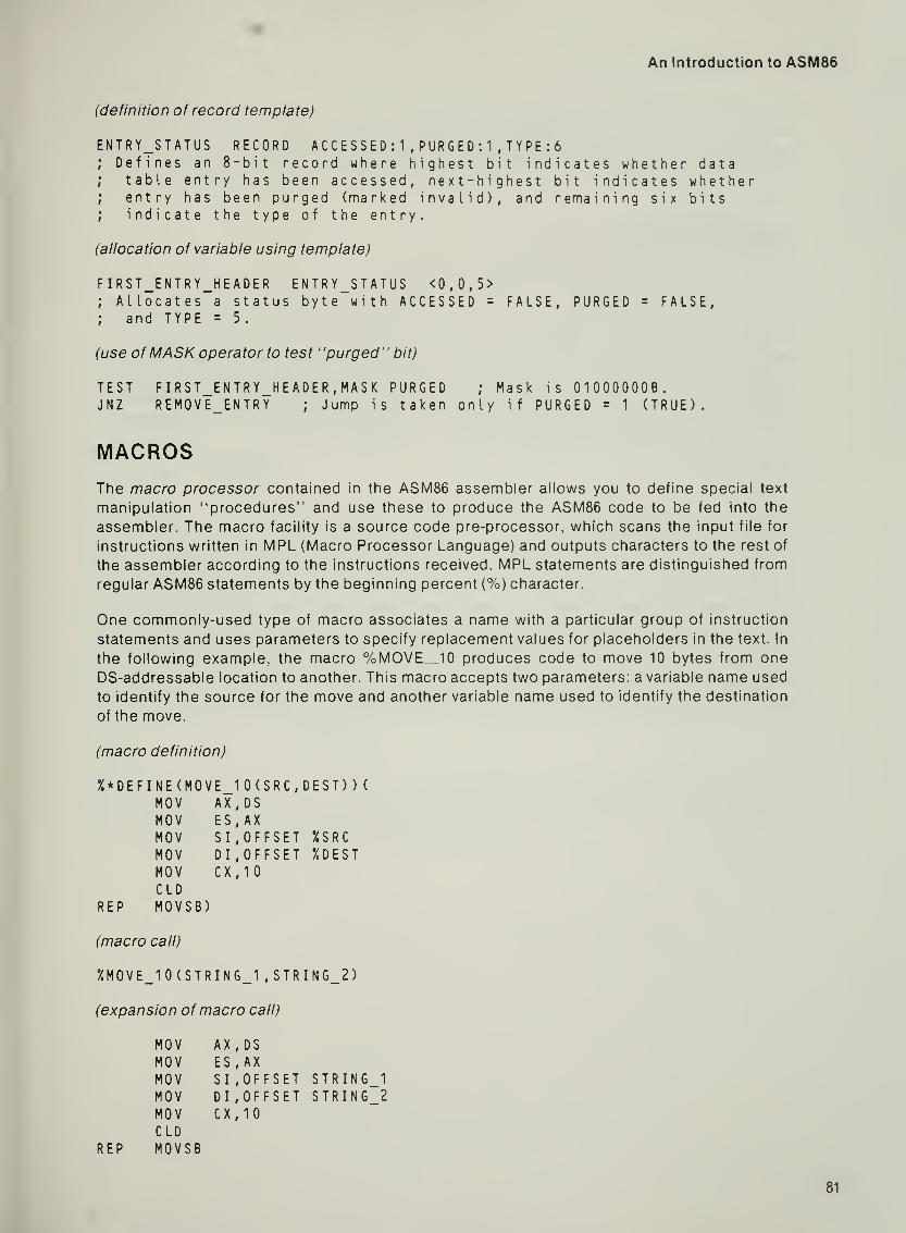
An Introduction to ASM86
(definition of record template)
ENTRY_STATUS RECORD A C C E S S E D : 1 , PU R G E D : 1 , T Y P E :
6
; Defines an 8-bit record where highest bit indicates whether data; table entry has been accessed, next-highest bit indicates whether;
entry has been purged (marked invalid), and remaining six bits; indicate the type of the entry.
(allocation of variable using template)
FIRST_ENTRY_HEADER ENTRY_STATUS <0,0,5>; Allocates a status byte with ACCESSED = FALSE, PURGED = FALSE,; and TYPE = 5.
(use ofMASK operator to test "purged" bit)
TEST FIRST_ENTRY_HEADER,MASK PURGED ; Mask is 01000000B.JNZ REMOVE_ENTRY
; Jump is taken only if PURGED = 1 (TRUE).
MACROSThe macro processor contained in the ASM86 assembler allows you to define special text
manipulation "procedures" and use these to produce the ASM86 code to be fed into the
assembler. The macro facility is a source code pre-processor, which scans the input file for
instructions written in MPL (Macro Processor Language) and outputs characters to the rest of
the assembler according to the instructions received. MPL statements are distinguished from
regular ASM86 statements by the beginning percent (%) character.
One commonly-used type of macro associates a name with a particular group of instruction
statements and uses parameters to specify replacement values for placeholders in the text. In
the following example, the macro %MOVE„10 produces code to move 10 bytes from one
DS-addressable location to another. This macro accepts two parameters; a variable name used
to identify the source for the move and another variable name used to identity the destination
of the move.
(macro definition)
%*DEFINE(MOVE_10(SRC,DEST))(MOV AX,DSMOV ES,AXMOV SI, OFFSET %SRCMOV DI, OFFSET 7.DEST
MOV CX,10C LD
REP MOVSB)
(macro call)
%MOVE_10(STRING_1 ,STRING_2)
(expansion of macro call)
MOV AX,DSMOV ES.AXMOV SI, OFFSET STRIN6_1MOV DI, OFFSET STRING_2MOV CX.IOC LD
REP MOVSB
81

er7 What's Next?
The above example shows one of many ways the macro processor can be used to produce
code for the assembler. By using MPL text processing instructions in your source file, you can
save yourself a lot of programming work and, at the same time, make your programs more con-
cise and easy to understand. For more information about the macro processor, see the
Reference Manual
.
ASSEMBLER CONTROLS
Special keywords in control lines (lines beginning with a $ in the first column) and in the
command tail are used to direct the assembly process. These keywords are called assembler
controls, since they tell the assembler what to do. Controls are used to specify whether or not
a listing is to be generated (PRINT/NOPRINT). if local symbol information should be put into
the object file (DEBUG/NODEBUG). if macros are used (MACRO/NOMACRO). etc. Most con-
trols have a default setting, so you need only specify settings other than the defaults. For
example, the defaults for the controls just mentioned are: PRINT. NODEBUG. and MACRO. If
you desire a listing, use macros, and want local symbol information to be placed in the object
file, you need only specify the DEBUG control, since PRINT and MACRO are automatic. Fur-
ther information about the assembler controls can be found in your Operating Instructions
manual.
CHAPTER SUMMARY
The purpose of this manual is to teach you the fundamentals of constructing an ASM86 source
module and provide the conceptual background you will need in order to write ASM86 code.
This manual covers only the basics: it does not provide complete coverage of Intel's 8086/8088
assembly language or of the ASM86 assembler. Some of the topics not covered here, but
described in detail in the Reference Manual, are: the 8086/8088 instruction set. the 8087 NDPinstruction set and data types, assembly-time expressions, structures, records, and macros.
The assembler controls are described in the Operating Instructions . Refer to your Reference
Manual and Operating Instructions for further, more detailed information about ASM86.

APPENDIX ASOURCE MODULE TEMPLATES
The diagrams that follow are ASM86 source module templates to be used with the PL/M-86
SMALL, COMPACT, MEDIUM, and LARGE models of computation. These templates show the
assembly language statements that make up the framework of each of the models. By starting
with one of these templates, you will spend a minimal amount of time worrying about ASM86directives and can concentrate on the task of defining data and writing code.
Using the Templates
The templates are designed to be used in a "fill in the blanks" fashion. The basic statements,
to be copied into your source file, are capitalized. The statements in angle brackets (<>) are
placeholders for text to be supplied by you. These statements are instructions to you; they
should not be copied into your source file.
Each template contains SEGMENT statements for all the segments used by PL/M-86 code.
You may define additional segments, as when you extend the SMALL model, and you may omit
segments that you will not be using. If you omit a segment belonging to a group, you must
remember not to name this segment in the GROUP statement. For example, you may be using
the SMALL model and have no need for the CONST and MEMORY segments. If these are
omitted from your source module, then the GROUP statement for DGROUP should only men-
tion the DATA and STACK segments:
DGROUP GROUP DATA, STACK
Facing each template is a notes section, which briefly summarizes some of the programming
considerations associated with the model. You should keep these in mind as you build your
assembly language module from a particular template.

Appendix A Source Module Templates
THE PL/M-86 SMALL MODEL OF COMPUTATION
NAME <module-name>
CGROUP GROUP CODEDGROUP GROUP CONST, DATA, STACK, MEMORY
ASSUME CS:CGROUP, DS:DGROUP, SSrDGROUP
CONST SEGMENT PUBLIC 'CONST'
<Program constants may be put here. >
CONST ENDS
DATA SEGMENT PUBLIC 'DATA'
E X T R N Kexternal variables>
<Define program data here. >
DATA ENDS
STACK SEGMENT STACK 'STACK'
<Use a DW statement tiere to add words to stack. >
STACK ENDS
MEMORY SEGMENT MEMORY 'MEMORY'
<This is a special data segment, above the other segments. >
MEMORY ENDS
CODE SEGMENT PUBLIC 'CODE'
E X T R N <external NEAR labels, such as procedure names><Put instruction statements here.>
CODE ENDS
END <Optional start-address, for main module only. >
Figure A-1. SMALL Model Template
84

An Introduction to ASM86
Notes on the SMALL Model
• Total program code is less than 64K bytes.
• Combined size of data, constant, stack, and memory regions is less than 64K bytes.
• The segment registers do not change: CS holds the base of CGROUP; DS and SS both
hold the DGROUP base.
• All procedures should be given type NEAR.
• Offsets of variables are group-relative, so the group override operator (DGROUP:) must
be used with the OFFSET operator and when initializing a DW to a variable's offset or
initializing a DD to a variable's base:offset address.
• All addresses are short pointers (offsets). Thus, the PL/M POINTER data type and @operator use a short (offset) address, just like the WORD data type and dot (.) operator.
85

Appendix A Source Module Templates
THE PL/M-86 COMPACT MODEL OF COMPUTATION
NAME <module-name>
CGROUP GROUP CODEDGROUP GROUP CONST, DATA
ASSUME CS:CGROUP, DS:DGROUP, SSrSTACK
CONST SEGMENT PUBLIC 'CONST'
KProgram constants may be put here. >
CONST ENDS
DATA SEGMENT PUBLIC 'DATA'
E X T R N <external variables>
KDefine program data fiere. >
DATA ENDS
STACK SEGMENT STACK 'STACK'
<Use a DW statement here to add words to stack. >
STACK ENDS
MEMORY SEGMENT MEMORY 'MEMORY'
<This is a special data segment, above the ottier segments. >
MEMORY ENDS
CODE SEGMENT PUBLIC 'CODE-
EX T R N Kexternal NEAR labels, such as procedure names><Put instruction statements here. >
CODE ENDS
END <Optional start-address, for main module only. >
Figure A-2. COMPACT Model Template
86

An Introduction to ASM86
Notes on the COMPACT Model
• Total program code is less than 64K bytes.
• Connbined size of data and constant regions is less than 64K bytes.
• Stack may be up to 64K bytes in size.
• Memory segment may be up to 64K bytes in size.
• The segment registers do not change: CS holds the base of CGROUP; DS holds the
DGROUP base; and SS holds the base of the STACK segment. ES should be used to
access the MEMORY segment and for indirect references using long pointers.
• All procedures should be given type NEAR.
• Offsets of variables are group-relative, so the group override operator (DGROUP:) must
be used with the OFFSET operator and when initializing a DW to a variable's offset or
initializing a DD to a variable's base:offset address.
• The PL/M POINTER data type and 'g operator use a long (base:offset) address, though
offset addressing is possible using the WORD data type and the dot (.) operator.
87

Appendix A Source Module Templates
THE PL/M-86 MEDIUM MODEL OF COMPUTATION
NAME <module-name>
DGROUP GROUP CONST, DATA, STACK, MEMORY
ASSUME CSrCODE, DS:D6R0UP, SS:DGROUP
CONST SEGMENT PUBLIC 'CONST'
KProgram constants may be put here. >
CONST ENDS
DATA SEGMENT PUBLIC 'DATA'
E X T R N <external variables>
KDefine program data here. >
DATA ENDS
STACK SEGMENT STACK 'STACK'
<Use a DW statement here to add words to stack.
>
STACK ENDS
MEMORY SEGMENT MEMORY 'MEMORY'
<This is a special data segment, above the other segments. >
MEMORY ENDS
E X T R N Kexternal FAR labels, such as procedure names>
CODE SEGMENT 'CODE'
<Put instruction statements here.>
CODE ENDS
END <Optional start-address, for main module only. >
Figure A-3. MEDIUM Model Template
88

An Introduction to ASM86
Notes on the MEDIUM Model
• Program code may exceed 64K bytes.
• Combined size of data, constant, stack, and memory regions is less than 64K bytes.
• The DS and SS segment registers hold the base of DGROUP and do not change. ESshould be used for indirect references using long pointers.
• Local procedures may have type NEAR, but all public and external procedures must have
type FAR.
• Offsets of variables are group-relative, so the group override operator (DGROUP:) mustbe used with the OFFSET operator and when initializing a DW to a variable's offset or
initializing a DD to a variable's base;offset address.
• The PL/M POINTER data type and (a operator use a long (base:offset) address, though
offset addressing is possible using the WORD data type and the dot (.) operator.
89

Appendix A Source Module Templates
THE PL/M-86 LARGE MODEL OF COMPUTATION
NAME <module-name>
ASSUME CSiCODE, DSiDATA, SS:STACK
EXTRN <external variables>
DATA SEGMENT 'DATA'
<Define program data here. >
DATA ENDS
STACK SEGMENT STACK 'STACK'
<Use a DW statement here to add words to stack. >
STACK ENDS
MEMORY SEGMENT MEMORY 'MEMORY'
<This is a special data segment, above the other segments. >
MEMORY ENDS
EXTRN <external FAR labels, such as procedure names>
CODE SEGMENT 'CODE'
<Put instruction statements here. >
CODE ENDS
END <Optional start-address, for main module only. >
Figure A-4. LARGE Model Template
90

An Introduction to ASM86
Notes on the LARGE Model
• Program code may exceed 64K bytes.
• Data region may exceed 64K bytes.
• Stack may be up to 64K bytes in size.
• Memory segment may be up to 64K bytes in size.
• The SS segment register holds the base of the STACK segment and does not change.
• The DS segment register holds the base of the local data region; thus, its value is different
for each module. The previous value of DS should always be saved when DS is reloaded,
and later restored.
• Local procedures may have type NEAR, but all public and external procedures must have
type FAR.
• All pointers passed between modules must be long (baseioffset) addresses. The PL/MPOINTER data type and @ operator use a long address.
• External variables use a different base than local variables. Thus, you must load DS or ESwith the appropriate segment base before addressing an external variable.
91


INDEX
64K, 13, 40, 45, 60 thru 63, 69, 85, 87, 89, 91
8086/8088 microprocessors, 9,11, 13 thru 16,
18, 22, 25, 27 thru 30, 36, 44, 75, 79
8087 numeric data processor (NDP), 79, 82
& (ampersand), 2, 3
@ operator in PL/ M-86, 69, 70, 85, 87, 89, 91
[ ](brackets), 28 thru 30
.(colon), 4, 17, 18, 31,46
$ (dollar sign), 3, 82
. operatorinPL/M-86,69, 70,85,87, 89
in structures, 80
% (percent sign), 81
? (question mark), 21 , 25, 26, 34, 66
;(semicolon), 2, 7
ABStype, 38
absolute code, 77
accessing data
see addressing modes, variable
referencesaddress, 5, 11 thru 15, 18, 19, 22, 27, 30, 31,
39,45,55,62,68,70calculation, 13, 14
starting
see start addressADDRESS data type (PL/M-86), 62
addressing, 10,11, 17 thru 19, 22, 27 thru 32,
35,41,42,59addressing modes, 25, 27 thru 30, 33, 36, 45,
57, 58, 68
see also direct offset addressing mode,indirect addressing mode, register-
offset addressing mode, two-register
addressing modeAL register, 3, 8, 59, 62, 66, 67, 69, 71
alias, 73, 74, 77
align-type attribute, 41 ,44, 60
see also BYTE align-type, PARA align-
type, WORD align-type
allocation of data
see data allocation
ambiguous statements, 32
ampersand (&), 2, 3
anonymous references, 31 thru 33, 36
array, 29, 35, 36, 52, 53
see also index
ASCII, 26, 28, 29
see also string
ASM86see assembly language
assembler, 1
assembler controls
see controls
assembler directives
see directives
assembly language, 1 , 3, 4, 8, 14
ASSUME statement, 18 thru 23, 31 , 32, 36, 45,
49, 60, 70
AT combine-type, 77
attribute
of logical segment, 40, 41 , 60
of variable, 26
override, 25, 30 thru 33
override operators, 30 thru 33, 36
attribute-list, 14, 40, 41
AX register, 3, 8, 59, 62, 70, 71 , 73
backward jump, 75
bad guess, 6
base, lOthru 13, 15, 18, 19, 21, 22, 27, 30, 31,
42, 44 thru 46, 49, 52, 54, 55, 59, 62, 69,
70, 77
base address, 13
base:offset addressing, 11,13, 15, 22, 25, 52,
55,60,69,70,87,89,91binary number, 2
bit-encoded data, 80
BP method of retrieving parameters,
57 thru 59,66,70,74
BP register, 3, 28 thru 31 , 57 thru 59, 66, 67, 71
brackets ([ ]), 28 thru 30
branching
see control transfer instructions
BX register, 3, 28 thru 30, 59, 62, 71 , 73
byte, 3, 25, 55, 56, 59, 62, 71
BYTE align-type, 44, 49
BYTE data type, 3, 6, 8, 15, 25 thru 27,
32 thru 35,38
calculating addressessee address calculation
CALL instruction, 15, 18, 40, 47, 48, 56, 59, 60,
62,70
CGROUP, 60 thru 62, 65, 69, 70, 85, 87
changing segment registers, 17, 18, 31
character string
see string
class-name attribute, 41 , 44, 60

Index
code, 1. 4, 6, 8. 14, 18, 23, 35, 37. 47,
52 thru 54, 60, 62, 69,70
generation, 1 , 3 thru 5, 8, 19, 23, 31 , 32, 39,
47, 48, 54
optimization, 75, 76
region, 9, 10, 12, 14, 15, 17, 39, 40, 44, 52
segment, 16, 18, 19, 21, 49, 70
CODE segment, 60, 61 , 65, 69
colon (:), 4, 17, 18, 31 , 46
combine-type attribute, 41 thru 43, 45, 49,
54, 60
see also AT combine-type,non-combinable segment, PUBLICcombine-type, STACK combine-type
combining logical segments, 37, 39 thru 45,
49,54,55,60,71comment, 2, 7, 8
COMPACT model of computation, 69, 83, 86,
87
conditional jump, 6, 74, 75, 77
CONST segment, 60, 61 , 69, 70, 83
constant, 2 thru 5, 7, 8, 38, 52
continuation line, 2, 3
control line, 3, 82
control transfer instructions, 18, 39, 40, 47,
60
controls, 82
CS register, 3, 11 thru 13, 16thru 19, 21, 22,
39,40, 47, 59 thru 62, 65, 70,71
CX register, 3, 28, 29, 36, 53, 59, 67, 68, 71 , 73
data, 1 , 8, 15, 16, 19, 22, 23, 25 thru 37, 48, 52,
60, 62, 69, 70
accesssee addressing modes, variable
referencesallocation, 25 thru 27, 33, 34, 36, 80, 81
allocation statements, 1 thru 3, 7, 8, 23, 25,
26,28,34,36,62region, 9 thru 15, 17 thru 20, 31 , 33, 39, 40,
44,45,48,49,52,62,63,69,91segment, 17 thru 19, 21 , 31 , 49, 59, 63, 70
type
see typeDATA segment, 60, 61 , 65, 69, 70, 83
DB statement, 3, 8, 9, 25, 26, 35, 36
DD statement, 3, 25, 26, 36, 85, 87, 89
decimal number, 2, 34
default
attribute of logical segment, 40, 41 , 44, 60
controls, 82
segment register, 28 thru 32, 45, 57
segment register assumptions, 19, 35, 77
define byte, 8
see also DB statementdefine word, 8
see also DW statementdefining variables
see data allocation, variable
destination
address, 67
index, 35
operand, 4
DGROUP, 60 thru 63, 65 thru 67, 69, 70, 83, 85,
87, 89
Dl register, 3, 28 thru 30, 35, 59, 67, 71
direct offset addressing mode, 27, 28, 30, 76
direction flag, 67
directives, 1, 2, 7, 8, 37, 83
see also statementsdollar sign ($), 3, 82
dot operator
inPL/M-86,69, 70,85, 87, 89
in structures, 80
double-word, 3, 25 thru 27
DS register, 3, 11 thru 13, 15 thru 19, 21, 22, 28
thru 31,33,39,40,42,44,45,52,59 thru 61, 63, 65, 67, 71, 91
DUP construct, 20, 21 , 26, 34, 66
DW statement, 3, 8, 20, 25 thru 27, 34, 36, 85,
87, 89
DWORD data type, 3, 15, 26, 32, 38
DX register, 3, 59, 71, 73
elements of ASM86 module, 1 thru 3, 37
empty stack, 15, 16, 22
see also register initialization
END statement, 8, 17, 22, 35, 36, 61
ENDP statement, 47, 48, 53, 54
ENDS statementin SEGMENT/ENDS pairs, 14, 15,
19 thru 21 , 23, 34, 36, 39 thru 41 , 49,
52, 53
inSTRUC/ENDS pairs, 80
entry point
see procedure entry point
epilogue of procedure, 58, 66, 67
EQU directive, 5, 8, 38, 52
equate, 5, 8, 73, 74
error, programmer, 4, 8, 32, 76
ES register, 3, 11 thru 13, 17 thru 19, 31, 33,
39,45,59,63,67,71expression, 4, 5, 28, 30, 32, 53, 68, 77, 79, 82
extending the SMALL modelsee SMALL model of computation
external symbol, 38, 39, 49, 66, 68, 70, 91
EXTRN directive, 38, 39, 52 thru 54, 70
FAR label, 4, 15, 18, 38, 47, 48, 57, 70, 89, 91
file
see listing file, object file, source file
flags
see register conventionsfloating point stack, 79
format of source file
see elements of ASM86 module,framework of source module, line-
orientation of statements, templateFORTRAN-86, 37, 55, 70
forward jump, 76
see also jump aheadforward reference, 6 thru 8
94

framework of source module, 36, 52, 60, 65,
70, 83
see also templatefunction, 49, 54, 59, 62, 66, 69, 70
see also procedurefunctional block, 37, 47, 54
general purpose mnemonics, 3, 4, 8
general purpose registers, 3, 15
generation of codesee code generation
group, 44 thru 46, 49, 52, 54, 55, 60, 62, 70, 71
,
83
name, 44 thru 46
offset, 46, 52,62, 66,85, 87, 89
override, 46, 52, 62, 85, 87, 89
GROUP statement, 44, 45, 49, 60, 70, 83
grpnamesee group name
hexadecimal number, 2, 8
high-level language, 37, 48, 54, 55
see also PL/M-86
identifier, 2, 4, 5, 14, 26
indeterminate initialization, 26, 34
see also data allocation
index, 29, 53, 63, 66, 67, 69
see also destination index, source index
indirect addressing mode, 28 thru 31
init, 25, 26, 34, 62
initialization of data
see data allocation
initialization of registers
see register initialization
instruction, 1, 4, 8, 9, 16thru 19, 21, 22, 27, 30,
32, 33, 35, 36, 39, 58
pointer
see IP register
set, 79, 82
statements, 1 , 2, 4, 6 thru 8, 79, 81
inter-module references, 37 thru 39, 54, 70
see also linking modulesinterrupt vector, 77
IP register, 16 thru 18, 40, 47, 48, 53, 59, 60,
62, 70, 71, 74, 75
jump, 18, 40, 60, 62, 77
ahead, 6, 7
backward, 75
conditional, 6, 74, 75, 77
forward, 76
vectored, 74, 75
see also SHORT jumpjump-around-jump, 74, 75
keywords, 2, 19, 82
label, 2, 4, 6, 8, 15 thru 19, 25, 37, 38,
46 thru 48, 54,55,61,62,70,73see also FAR label, NEAR label
An Introduction to ASM86
LABEL directive, 15, 18, 21 , 42, 73, 77
languagesee assembly language, high-level
language, PL/M-86LARGE model of computation, 55, 69, 70, 83,
90,91
last-in first-out (LIFO), 15, 42
line-orientation of statements, 2
LINK86 (linker), 38, 39, 42
linking modules, 37 thru 39
listing file, 1
loading segment registers
see changing segment registers, register
initialization
LOC86 (locator), 44
local variables, 70, 91
location
counter, 77
in codesee label
in data
see variable
logical segment, 14, 15, 19, 22, 26, 31, 37,
39 thru 42,44,52,54,55,60,77long conditional jump, 74, 75
long pointer, 55, 56, 59, 60, 69 thru 71, 87,
89, 91
loop, 22, 29, 35, 36, 53, 54,68loop counter, 28, 29, 36, 53, 68
machine instruction
see instruction, opcode, operandmacro, 81, 82
processor, 81, 82
processor language (MPL), 81 , 82
main module, 8, 17, 61, 63, 65, 68
MASK operator, 80, 81
MEDIUM model of computation, 69, 70, 83,
88, 89
megabyte, 13
memory, 9, 10, 13, 18, 19, 22, 39, 59 thru 61
see also physical memoryMEMORY segment, 60, 61 , 69, 70, 83, 87
mnemonic, 1 thru 5, 8, 9, 15
model of computation, 55, 60, 62, 63, 65,
69 thru 71,83
see also COMPACT model of
computation, LARGE model of
computation, MEDIUM model of
computation, SMALL model of
computationmodular programming, 37, 47, 54, 55
modulesee main module, object module, source
modulemodule name, 7
MOV instruction, 4, 5, 8, 15
NAMEdirective, 7, 22, 36
NEARjump, 75, 76
95

Index
label, 4, 15, 18, 19, 22, 38, 47, 48, 53, 57, 62,
66, 69, 75, 85, 87, 89, 91
nibble, 13, 33, 36
non-combinable segment, 41, 66, 70
NOP (no operation) instruction, 6
NOTHING, 19, 35
number, 2 thru 4, 8, 76, 77
see also constant
numeric data processor (NDP), 79, 82
object file, 1, 7, 38, 39
object module, 7, 22
octal number, 2
offset, 10 thru 16, 19, 22. 25 thru 27, 29, 30, 32,
34 thru 36, 41 thru 46, 49, 52 thru 55,
59 thru 62, 66, 67, 69, 70, 73, 76, 77, 85,
87, 89
see also base:offset addressingOFFSET operator, 16, 22, 46, 62, 79, 85, 87, 89
opcode, 3, 4, 8, 18, 74, 75
operand, 1, 3, 4, 8, 9, 15, 18, 19, 32, 33, 47, 56,
57, 67, 68
operand type, 3 thru 5, 8, 32, 33
operating instructions (manual), 79, 82
operator, assembly-time, 79, 80
optimization of codesee code optimization
ORG directive, 77
override
see attribute override, segment override
packed number, 33, 34
PARAalign-type, 44, 60
paragraphalignment, 13, 44
boundary, 13, 44
number, 13, 77
parameter, 29, 47, 48, 54 thru 57, 59, 60,
66 thru 70,74,81
parameter passing, 37, 45, 48, 54 thru 56, 69,
70
parameter retrieval
see retrieving parametersPASCAL-86, 37, 55, 70
percent sign (%), 81
physical
address, 13, 14
memory, 13, 44, 69, 77
segment, 13, 14, 40, 44, 45, 60, 63
placeholder
in object module, 39
in template, 83
placement of EXTRNs, 39, 52, 53
PL/ M-86, 37, 54 thru 71 , 83 thru 91
data types
see ADDRESS data type, POINTERdata type
model of computationsee model of computation
parameter-passing method, 48, 55, 56, 70
procedural interface, 55 thru 60, 62, 63, 66,
69 thru 71
register conventionssee register conventions
pointer, 44, 55, 60, 62, 71
see also long pointer, short pointer
POINTER data type (PL/M-86), 69, 70, 85, 87,
89,91
POP instruction, 15, 16, 22, 59
pop method of retrieving parameters,56 thru 59,68,70
prefix byte
see segment override prefix bytepreserving registers
see register conventionsPROC directive, 18, 47, 48, 53, 54
procedural interface
see PL/M-86 procedural interface
procedure, 29, 37, 47 thru 49, 53 thru 59,
62 thru 71
call
see CALL instruction, parameterpassing
entry point, 47, 48, 53, 54
return
see RET instruction
scope, 48
value-returning
see function
procnamesee procedure entry point
prologue of procedure, 58, 66, 74
PTR operator, 32, 33, 76, 77
PUBLIC combine-type, 41 , 42, 45, 49, 70
PUBLIC directive, 38, 54
public symbol, 38, 39, 49, 52, 53, 66, 69, 70
PUSH instruction, 15, 16, 22
question mark (?), 21 , 25, 26, 34, 66
QWORD data type, 79
record, 80, 82
reference manual, 79, 80, 82
references
see anonymous references, inter-module
references, variable referencesregister, 3, 5, 8, 11 thru 13, 27 thru 30, 32, 33,
36,48,49,56,59,61,70see also listings by name: AL,AX,BP,BX,
CS,CX,D1,DS,DX,ES,IP,SI,SP,SSconventions, 57, 59, 71
initialization, 15 thru 17, 19, 22, 23, 31, 35,
52, 61
register-offset addressing mode, 29, 30, 35
relocatable code, 77
reserved w/ords
see keywordsRET instruction, 15, 18, 47, 48, 53, 54, 56, 57,
59, 67, 68
96

retrieving parameters, 48, 56 thru 59, 66
see also BP method of retrieving
parameters, pop method of retrieving
parametersreturn address, 9, 15, 47, 53, 56 thru 58, 62,
67,70,71
returning values from a proceduresee function, procedural interface
scope of procedures, 48
segmentattributes
see align-type attribute, class-nameattribute, combine-type attribute
combinationsee combining logical segments
name,14,15, 19,22, 40,42, 44,45
override, 30 thru 33, 68
override operator, 31 , 32, 35, 36, 77
override prefix byte, 18, 19, 31 , 32, 35, 39
register, 3, 11 thru 15, 17 thru 19, 22, 23, 27,
31,32,36,39,41,44,55,61,62,77see also listings by name:
CS,DS,ES,SS, changing segmentregisters, register initialization
register value, 13
see also logical segment, physical
segmentSEGMENT directive, 14, 15, 19 thru 21, 23, 34,
36, 39 thru 41 , 49, 52, 53, 60, 70, 83
segmentation, 9 thru 23
segnamesee segment name
semicolon (;), 2, 7
separate assembly/compilationsee linking modules
SHORTjump, 75 thru 77
SHORT operator, 76
short pointer, 55, 59, 60, 69, 71 , 85
SI register, 3, 28 thru 30, 35, 59, 67, 71
SMALL model of computation, 55, 60 thru 70,
83 thru 85
extensions, 62, 63, 83
procedural interface, 62, 63, 66
sourceaddress, 67
file,1,2,6thru9, 14,17, 54,79
index, 35
module, 7, 19, 22, 33, 37, 38, 49, 54, 82
operand, 4
SP register, 3, 15, 16, 22, 35, 42, 52, 57 thru 59,
61,67,68,71
special characters, 2
SS register, 3, 11 thru 17, 19, 22, 28 thru 30,
35,44,45,52,57,59 thru 61,71
stack, 9, 14 thru 16, 22, 39, 40, 42 thru 44, 47,
48, 53, 55 thru 60, 62, 66, 69 thru 71 , 74
An Introduction to ASM86
frame, 58, 59, 67
pointer
see SP register
region,9, 10,12,14, 15, 17, 39,40,
42 thru 45,49,52,62,63segment, 15, 21 , 49
STACK combine-type, 42, 43, 45, 49, 70
STACK segment, 60, 61 , 65, 66, 69, 70, 83, 87,
91
start address, 8, 17, 35, 61
statements, 1, 2, 8, 15
see also directives
string, 2, 26
string move instruction, 67
STRUC statement, 80
structure, 80, 82
subroutine
see proceduresupport procedure, 63 thru 69
symbolsee equate, external symbol, identifier,
keywords, label, public symbol,variable
TBYTEdata type, 79
template, 60, 70, 71 , 80, 81 , 83, 84, 86, 88, 90
text manipulation, 81
top of the stack region, 15, 16, 22, 42, 43, 52,
61,62
two-register addressing mode, 30, 35
type, 3, 4, 8, 18, 25, 26, 28, 30, 32 thru 34, 38,
47, 48, 76, 80, 82
conflict, 4, 8, 32
information, 3, 4, 8, 18, 27, 32, 33, 36, 38
override, 30, 32, 33, 68
override operator, 32, 33, 35, 36, 73, 76
unitialized data, 21, 26, 34
unpacked number, 33, 34
variable,2,3,7, 8, 11,12, 14thru 22,
25 thru 28, 30 thru 34, 36 thru 38, 42,
44 thru 46, 48, 49, 52, 55, 56, 60, 62, 73, 85
attributes, 26, 30
offset, 26 thru 28, 30, 32, 34, 36, 73
segment, 26 thru 28, 30 thru 32, 34, 36, 73
type, 26 thru 28, 30, 32 thru 34, 36
references, 27, 28, 31 , 32, 35, 36, 54, 70, 76
vectored-jump, 74, 75
volatile registers
see register conventions
word,3, 13, 25, 55, 56, 59,62,70
WORD align-type, 44, 49
WORD data type, 3, 6, 8, 15, 25 thru 27, 32, 33,
35, 38, 69, 70, 85, 87, 89
97