An Intelligent Peripheral in the Intelligent Network - TU/e
142
Eindhoven University of Technology Faculty of Electrical Engineering Information and communications systems group P.D.Box 513 5600 MB Eindhoven The Netherlands Ericsson Telecommunications Division R&D IN Application Laboratory P.D.Box 8 5120 AA Rijen The Netherlands An Intelligent Peripheral in the Intelligent Network A. Ventevogel Graduation Report Rijen, January 1997 Coaches: Prof.ir. J. de Stigter (TUE) ir. J. van der Meer (Ericsson) The Faculty of Electrical Engineering of the Eindhoven University of Technology does not accept any responsibility regarding the contents of student projects and graduation reports
Transcript of An Intelligent Peripheral in the Intelligent Network - TU/e

Eindhoven University of TechnologyFaculty of Electrical EngineeringInformation and communications systems groupP.D.Box 5135600 MB EindhovenThe Netherlands
Ericsson TelecommunicationsDivision R&D
IN Application LaboratoryP.D.Box 8
5120 AA RijenThe Netherlands
An Intelligent Peripheralin the Intelligent Network
A.Ventevogel
Graduation Report
Rijen, January 1997
Coaches:
Prof.ir. J. de Stigter (TUE)ir. J. van der Meer (Ericsson)
The Faculty of Electrical Engineering of the Eindhoven University of Technology does not accept any responsibilityregarding the contents of student projects and graduation reports

Preface
This report fonns the conclusion of my Master's thesis, fulfIlled as a part of the electricalengineering studies at the Eindhoven University of Technology. Between March 1996 andJanuary 1997 I worked at the Intelligent Networks Application Laboratory (INAL), part of theR&D division of Ericsson Telecommunicatie B.V. in Rijen, the Netherlands.
In the INAL I was given the opportunity to work on the RSP-tool project. The main goal of theproject is to gain insight in the consequences and demands of introduction of IntelligentNetworks. For me, working in this project was an opportunity to experience the way ofworking in a research & development department of a big company. Also, it gave me theopportunity to apply the theoretical knowledge on the area of telecommunications to a practicalproblem in the area of Intelligent Networks.

Acknowledgments
At this point I would like to thank prof.ir. J. de Stigter for taking the responsibility for mygraduation project, his interest in my progress and his useful comments.
Also I would like to thank Jan van der Meer for accepting my project at the IN ApplicationLaboratory, and for his competent and nice coaching during the project.
Furthermore, I would like to thank my colleagues at Ericsson Telecommunication B.V. inRijen, in special Barbara Bomkamp, Yun-Chao Hu, Lucas Klosterman, YuZhang Liu, andAndre Marinissen, for their fruitful discussions and being nice colleagues. Special thanks toJohn Kroeze, Erik Reitsma, and Erik van der Velden for their actual help on someimplementation issues, next to being nice colleagues.
Finally and foremost, I would like to thank my girlfriend Ieteke, my parents, and all my friendsfor their support during my study. Their support gave me the energy, the joy, and theinspiration to persevere in difficult periods.
January 1997Andre Ventevogel
iii

Summary
Intelligent Networks enhance the existing telephony network with possibilities to provide avariety of services to the users. Especially in these days of competition introduced in thenetwork, and of fast evolving technologies, this gives operators the opportunity to distinct fromothers, and thus become more interesting for customers. Ericsson Telecommunications is aleading company on the area of Intelligent Networks.
The Intelligent Networks Application Laboratory (INAL), part of the R&D division ofEricsson Telecommunicatie B.V. in Rijen, is instituted to make full profit out of theopportunities provided by the Intelligent Network concept.
One of the projects in the INAL, the Rapid Service Prototyping (RSP) tool is a model of thereal Ericsson Intelligent Network. It provides Ericsson a means to get insight in theconsequences and demands of the introduction of new services in the Intelligent Network on thenodes in the network and on the network capabilities. Also, the RSP-tool makes it possible totest new ideas within a very short time.
However, the RSP tool is not complete yet. One of the missing parts is a physical entity thatcontains specialized resources in the network, the Intelligent Peripheral (IP). This IntelligentPeripheral takes care of specialized tasks in the network, such as recording and playing ofspeech messages. To get the full potential out of the Intelligent Network capabilities, theIntelligent Peripheral is a very important node.
In this document I provide an overview of the research to such an Intelligent Peripheral,especially aimed on the wish to extend the RSP-tool with such a node. First, the researchconcentrates on the functional aspects of an Intelligent Peripheral. The result of this research isa set of capabilities, which the IP should at least provide. The capabilities of the prototype,which will be developed, will be used in a service, that is also described in the report. Animportant issue is the distribution of logic in the Intelligent Network, and this will be describedextensively.
The research also covers the architecture of an Intelligent Peripheral, dealing with aspects likescalability and modularity. The research results in a proposal for the architecture of theprototype of the Intelligent Peripheral, which has to interwork in the RSP-tool.
Furthennore, research to the interfaces of an Intelligent Peripheral is needed. To integrate theIntelligent Peripheral in the existing telephony network, two options are described, and one ofthe options is selected to be used in the prototype in the RSP-tool.
Before the results of the research are used to implement the prototype, the report describes afonnal description of the system. The Specification and Description Language, SOL, is used todescribe and explain the breakdown of the prototype in four functional blocks. It also describesthe processes in the prototype on a detailed level.
Finally, the report describes the implementation issues of the prototype Intelligent Peripheral.In this implementation, the results of the research are used as a guideline. The report describesthe hardware and software architectures, needed to provide the prototype with the demandedcapabilities and interfaces to the RSP-tool in the Intelligent Network Application Laboratory.
v

Contents
PREFACE I
1. INTRODUCTION 1
1.1 SCOPE OF THE PROIECT 11.2 PROBLEM DEFINITION 21.3 PROIECTINFORMATION 21.4 REPORT OUTI..INE 2
2. BACKGROUNDS 5
2.1 INTELLIGENT NE1WORKS 52.1.1 Objectives ofIntelligent Networks 62.1.2 Scope ofIntelligent Networks 62.1.3 Conceptual model 62.1.4 Service Plane 72.1.5 Global Functional Plane 72.1.6 Distributedfunctional plane 92.1.7 Physical Plane 102.1.81nterfaces 12
2.2 ERICSSON INTELLIGENT NE1WORK 122.2.1 Service Management Application System 132.2.2 Service Control Point 152.2.3 Service Switching Point 152.2.41nterfaces 15
2.3 THE RSP TOOL 162.3.1 Environment 162.3.2 The Line Interface Module 172.3.3 The software 18
2.4 SPECIAUZED REsOURCES 212.4.1 General aspects 222.4.2 Available resources 25
2.5 CONCLUSIONS 26
3. FUNCTIONAL ASPECTS 29
3.1 FuNCTIONAL REQUIREMENTS OF A GENERIC IP 293.1.1 Resource requirements 293.1.2 Management requirements 303.1.3 Service processing requirements 323.1.4 Functional model 36
3.2 THEPROTOTYPEIP 383.2.1 Prototype benchmark service 393.2.2 Functional model ofprototype 44
3.3 CONCLUSIONS 453.3.1 Generic IP 453.3.2 Prototype IP 46
4. ARCIDTECTURAL ASPECTS _.....•....................................49
4.1 DESIGN PHILOSOPHY 494.2 lIARDwARE ARCHITECTURE OF A GENERIC IP 504.3 SOFIWARE ARCIDTECTURE OF A GENERIC IP 544.4 ARCHITECTURE OF THE PROTOTYPE IP 56
4.4.1 Hardware architecture 564.4.2 Software architecture 59
4.5 CONCLUSIONS 61
vii

An Intelligent Peripheral in the Intelligent Network
s. INTERFACES.................................•.........................................•..............•..................................63
5.1 SIGNALING AND PROTOCOLS 635.1.1 Signaling 635.1.2 Protocols 645.1.3 Signaling System No.7 665.1.4 ISDN signaling 71
5.2 INTERFACES TO A GENERIC INTELLIGENT PERIPHERAL 735.2.1 The Switching Interface 745.2.2 The Control Interface 765.2.3 The Management Interface 80
5.3 INTERFACES TO TIiE PROTOlYPE INTELLIGENT PERIPHERAL 815.3.1 The SSF interface 825.3.2 The SCF interface 825.3.3 The NMF interface 835.3.4 The SMF interface 83
5.4 CONCLUSIONS 84
6. TIlE MODEL OF TIlE INTELLIGENT PERIPIlERAL 85
6.1 THE SPECIFICAnON AND DESCRIPTION LANGUAGE SDL. 856.2 THE SDL MODEL ON SYSTEM LEVEL 866.3 THE SDL MODEL ON BLOCK LEVEL 876.4 THE SDL MODEL ON PROCESS LEVEL 89
6.4.1 The Access Part 896.4.2 The Control Part 916.4.3 The Resource Part 956.4.4 The Switch Part 97
6.5 THE MESSAGE SEQUENCE CHART 976.5.1 The setup phase 986.5.2 The processing phase 986.5.3 The disconnect phase 99
6.6 CONCLUSIONS 100
7. TIlE IMPLEMENTATION OF TIlE PROTOTYPE 103
7.1 OVERVIEW OF TIiE DESIGN OF TIiE IMPLEMENTAnON 1037.2 THE IMPLEMENTATION OFF TIiE MODEL 106
7.2.1 The Access Part 1077.2.2 The Switch Part 1087.2.3 The Resource Part 1087.2.4 The Control Part 1107.2.5 Other software 111
7.3 SCRIPTS AND BUILDING BLOCKS IN TIiE SCP AND IP 1117.4 THE BUILDING BLOCKS 114
7.4.1 The SCF building blocks 1147.4.2 The IP building blocks and scripts 117
7.5 TESTING OF THE IMPLEMENTAnON OF TIiE IP 1227.6 CONCLUSIONS 124
8. CONCLUSIONS 127
8.1 CAPABILITIES OF TIiE INTELLIGENT PERIPHERAL 1278.2 ARCHITECTURE OF THE INTELLIGENT PERIPHERAL 1278.3 INTERFACES OFTIiEINTELLIGENTPERIPHERAL 1288.4 PROTOlYPE IMPLEMENTAnON 1288.5 RECOMMENDAnONS AND FUTURE WORK 129
REFERENCES 133
ANNEX A : CODE OF PA40 BUILDING BLOCK 139
viii

1. Introduction.This chapter provides the reader an introduction to the subject of this report. It identifies theproblem and defines the scope of the project. Next the project is put in a broader context. Finally itgives the outline of the report.
1.1 Scope of the project.Nowadays the telecommunication market is a very fast evolving one. Not only the new, hottopics like broadband, mobile and ISDN are demanding big investments of thetelecommunication industries. Also POTS (plain Old Telephone Service) is evolving towards aservice-level that requires innovation and big investments from operators and equipmentvendors. The demands from both big companies and individual subscribers constantly increasesand operators need to satisfy their customers to keep in line with their competitors.
In the old telephony networks the call control and service control are often integrated in theswitches. This causes problems when new services have to be introduced in the network. Itmakes it a difficult and slow process, because each service and its next releases has to beinstalled in every switch. Next to that, operators often use equipment from several vendors,which makes the introduction of new service even more difficult.
To make it possible to introduce new services quickly, the telecommunication industries, incooperation with the standardization institutes, have been defming the Intelligent Networkconcept. This concept separates the service control from the call control. The call controlremains in the switches, while the service control is put into a general purpose computerplatform. To install a new service only the software in the computer platform has to bechanged, instead of making adaptations in all the switches. Next to the advantage of fastintroduction of new services, the use of general purpose computers increases the possibilities tooffer more sophisticated services. Examples of these services are the Virtual Private Network(VPN) and Universal Personal Telephone (UPT) services.
In the past few years Ericsson made its own Intelligent Network implementation, based ontechnology that has already been used in the switches before the IN concept arose. TheEricsson IN system is used as special services platform by many operators (Le. Dutch PTT) in28 countries. The system makes it possible to create services in a graphical service creationenvironment. Also functionality for administration, network management and servicemanagement is provided in the system.
With the growing complexity of services there is an increasing need for a good user-interface.To achieve this, using the limited possibilities of the present terminals, there is an extensive useof menu's leading the user to the desired destination. These menu's require the playing ofannouncements and the recognition of digits, entered on the users' terminal. The resourceswhich take care of this are often located in the local- and transit exchanges.
To simplify the maintenance and installation of these resources the IN concept provides thepossibility to place the resources in a separate network node. The IN terminology for thecollection of resource functions is Specialized Resource Function (SRF). The physical node onwhich these functions reside is called Intelligent Peripheral (IP). The centralized placement ofthe resources in an IP makes it easy to extend the number of resources or to install newresource functionality, e.g. speech storage, speech recognition and protocol conversionfacilities.
1

An Intelligent Peripheral in the Intelligent Network
Till now the telecommunication industries have concentrated mainly on the telecommunicationaspects of the Intelligent Network concept. Therefore, few effort has been put on thespecialized resource functionality and architecture. In contradiction to this, in the computerfield the development of resources is going very fast. The resources often have the samefunctional requirements as the ones needed in the telecommunication field, and it would be goodto integrate these resources in the network.
The research to several aspects of the specialized resource function is the subject of thisproject.
1.2 Problem definition.This document describes my research on the SRF, it identifies functional requirements, itdermes a possible architecture and takes care of the interfacing aspects, thereby keepingstandardization and flexibility in mind.
The international standardization institutes (ITU, ETSI, ANSI) prescribe several aspects of theSRF, like architecture, functionality and interfacing. Next to the fact that theserecommendations leave much room for individual interpretation, it is a good thing to study theseveral aspects of the SRF outside the scope of the standardization documents.
The result of the research is to be demonstrated in an Intelligent Peripheral prototype. Thisreport describes the implementation of this prototype. The prototype has to interwork in theexisting prototyping environment, which has been developed by Ericsson in the past few years.This prototyping environment, the RSP (Rapid Service Prototyping) tool, consists of a softwaremodel of the Intelligent Network, which simulates the behavior of the real Ericsson IntelligentNetwork. This software model controls the low level hardware.
Finally, the prototype has to be tested. This is done by running a benchmark service, whichuses the resources in the implemented Intelligent Peripheral. The benchmark service is dermedin this document.
1.3 Project information.The Intelligent Networks Application Laboratory (INAL) was officially started end 1993. Itcovers a time-frame from 2 to 5 years from now. Several projects are running to investigaterequired network capabilities for future service applications. Current projects tackle e.g. datadistribution and service management aspects. Also, INAL participates in IN-standardization,focusing on the time-frame mentioned above. In the past years an IN-simulator tool, the RapidService Prototyping (RSP) tool is developed. This tool makes it possible to test new ideas.However this RSP tool is not complete. To enhance the functionality covered by the RSP tool aSpecialized Resource Function is to be included. This Specialized Resource Function (SRF) issubject of my graduation project. Several aspects are studied and a prototype is developed,which has to be integrated in the RSP tool.
1.4 Report outline.
This section provides a brief synopsis of the remaining chapters of the report.
Chapter 2 provides the user with some basic concepts used in this report. This helps the readerto understand the rest of the report. The topics described in the chapter are listed below.- Intelligent Networks: This subsection describes the objectives, benefits and structure ofIN.- Ericsson IN: This subsection contains some Ericsson specific IN-information.- The RSP-tool : This subsection describes the existing prototyping environment.- specialized resources: This subsection covers important aspects on specialized resources.
2

Introduction
Readers who are already known to the concepts described here, can skip the concerningsubsections.
Chapter 3 covers the functional aspects of the Intelligent Peripheral. It describes therequirements of the Intelligent Peripheral, and lists the capabilities that the resources shouldprovide. It also covers the management requirements and the service processing requirements.It describes the concept of distribution of logic in the Intelligent Network, and presents afunctional model for the Intelligent Peripheral.
Chapter 4 describes the architecture of the Intelligent Peripheral. It identifies important issueson the architecture of Intelligent Peripherals. It presents a software and hardware architectureof a generic Intelligent Peripheral. It also applies the results of the research on a proposal forthe architecture of the prototype Intelligent Peripheral.
Chapter 5 describes the interface aspects of the Intelligent Peripheral in the Intelligent Network.It covers the interfaces towards the Service Control Point, the Service Switching Point, themanagement entities, and to the Internet. It identifies several possible configurations for theinterfacing of an IP.
Chapter 6 describes the model of the prototype Intelligent Peripheral. It describes the model bymeans of the Specification and Description Language SOL. It identifies three levels ofabstraction for the model; system level, block level, and process level. Finally, it describes themodel by means of a Message Sequence Chart, indicating message flows between processes.
Chapter 7 describes the implementation of the prototype Intelligent Peripheral. It applies theresult of the research in the previous chapters to the prototype implementation. It describes howthe model described in chapter 6 is integrated in the prototype, and how building blocks can beused to create scripts that can be executed by the Intelligent Peripheral.
Chapter 8 gives the results of the research, and some recommendations for future work on thearea of the Intelligent Peripheral.
3

2_ Backgr_ou_D_d_s_- _This chapter introduces some basic concepts used in this document It is meant for people who areunfamiliar to these concepts. The purpose is not to be complete, but the interested reader will fmdreferences for detailed information. First the general concept of Intelligent Networks is described.This is done according to the ITU standardisation documents Q.1200. The next subsection describessome deviations from these standardised IN concepts in Ericssons implementation. The thirdsubsection gives a short introduction in the Rapid Service Prototyping tool, which is developed bythe Intelligent Network Application Laboratory in the past few years. This is the environment inwhich the SRF prototype has to be integrated. Finally, the last subsection covers some generalaspects on specialised resources in telecommunication networks. The integration of new media, theintroduction of new techniques, the position of special resources in the network, and other aspectsare described. The last subsection also lists the resources available for the implementation of theprototype IP.
2.1 Intelligent Networks.Traditionally, customers needing telecommunication selVices were highly depending on thetelecommunications operators. However, with the introduction of an open telecommunicationmarket, customers are given the opportunity to choose between telecommunication operators.Business customers of today use more and more sophisticated technology to support theoperation of their company. The need for more sophisticated telecommunication selVices hasincreased considerably and a fast introduction of these selVices is necessary for thetelecommunication operators to compete in the market.
However, to install new selVices the telecommunication operators depend on the switchmanufacturers. The infrastructure of the telecommunication operator is implemented usingswitches supplied by different manufacturers. SelVices in the infrastructure are implemented asdedicated software inside the switches and new selVices can therefore only be developed byswitch manufacturers. To introduce a new selVice, the operator has to negotiate with severalswitch manufacturers, who have to adapt all the switches to offer these new selVices.
The above mentioned reasons makes the introduction of new selVices a long and troublesomeprocess.
Intelligent Networks solves the problems of the telecommunication operators by moving theintelligence for support of the selVices out of the switches into general purpose computerplatforms. New selVices can be introduced by adding new software onto these computerplatforms. This can be done by the operators themselves, but also by other parties such assoftware houses. So the introduction of Intelligent Networks concept make the operators nolonger dependent on switch manufacturers for the development of new selVices.
To be independent of the switch manufacturers, the interface between switches and generalpurpose computer platforms have to be standardized. The standardization of IntelligentNetworks is described in ITU's (formerly CCITT) Q.l200 series [Q.1200]. The structure ofthese Q.1200 series enables the ITU to defme so called Capability Sets (CS). The ten's digitsdefme the number of the CS. At this moment CS-l (Q.121x) is approved, CS-2 is draft nowand will be approved March 1997, and CS-3 studies started May 1995 and will probably beapproved end 1998.
The ones digits in the Q.1200 series defme the subject of the Recommendation. For example,Q.1215 describes the physical plane for CS-l, and Q.l228 describes the interfacerecommendations for CS-2.
5

An Intelligent Peripheral in the Intelligent Network
This section describes the Intelligent Network according to recommendations Q.12Ox. Theserecommendations describe the general aspects of IN, and are independent of the CapabilitySets.
The European Telecommunications Standards Institute (ETSI) defmed its own IN standards.These standards are based on the ITU Q.1200 series. The main and most important differenceis in the defmition of the Intelligent Network Application protocol (INAP), which will bedescribed in subsection 2.1.8.
2.1.1 Objectives of Intelligent Networks
Intelligent Networks are aiming at the introduction of additional capabilities in atelecommunication network. They facilitate service/network implementation independentprovisioning of services in a multi-vendor environment [Q.1201].
Summarized, the Intelligent Network concept solves the vendor dependencies problem by:
• Moving the •intelligence' out of the switches into general purpose computer platforms.
• Defming interfaces between the switches and the computer platforms so that vendorindependence can be realized.
2.1.2 Scope of Intelligent Networks
The scope of IN contains a wide variety of networks, including but not limited to the PublicSwitched Telephone Network (PSTN), the Packet Switched Public Data Network (PSPDN),mobile networks (e.g. PLMN,GSM) and Integrated Services Digital Network (ISDN, bothnarrow band and broadband).
IN supports a wide variety of services, including supplementary services, and utilizes existingand future bearer services (e.g. those defmed in N-ISDN and B-ISDN contexts).
2.1.3 Conceptual modelAn Intelligent Network is an architectural concept that can be applied to anytelecommunication network. The model that captures this concept is called the IntelligentNetwork Conceptual Model (lNCM). The INCM specifies the framework for the design anddescription of any Intelligent Network based network. For example, the concept of IntelligentNetworks can be applied to public switched data telecommunication networks, mobile networksand integrated services digital networks (ISDN).
The INCM consists of four planes. Each plane specifies an Intelligent Network from a differentlevel of abstraction:
• Service Plane describing what a service (feature) must do.
• Global Functional Plane describing how it is done, without taking distributions aspectsinto account.
• Distributed Functional Plane describing how it is done, including the distribution aspects.
• Physical Plane describing how it is done, including the physical aspects.
The four planes with an example of the entities they contain and a mapping of entities from aplane onto another plane, are depicted in Figure 2.1. Each of the planes will be sketched in thenext subsections, except the service plane, since this plane is not yet described in [Q.1202].
6

Backgrounds
Service Plane
, .
Global Functional Plane
Distributed Functional Plane
Physical Plane
Figure 2.1: Intelligent Network Conceptual Model
2.1.4 Service Plane
The Service Plane (SP) is described in [Q.1202]. The SP represents a service-oriented view onIN. This view contains no infonnation whatsoever regarding the implementation of the servicesin the network. Only the network's service related behavior as seen, for example, by a user isdescribed. At this point it is valuable to consider the defmition of a service and service featurewithin the IN context as stated by the lTV recommendations [Q.1202].
A service is defmed as a stand-alone commercial offering, characterized by one or more coreservice features, which can be optionally enhanced by other service features.
A service feature is a specific aspect of a service that can also be used in conjunction withother services or service features. It is either a core part of a service or an optional part offeredas an enhancement to a service.
Furthennore the SP mentions the problem of service and service feature interaction. Service orservice feature interaction occurs when one service/service feature influences the behavior ofanother service/service feature in an unexpected (unwanted) way.
Next to usual telecommunications services, the SP also contains management related services.These services provide IN management aspects of services, e.g. customer control, charging,statistics collecting, service deployment and service provisioning.
2.1.5 Global Functional Plane
The Global Functional Plane (GFP) is described in [Q.1203]. The GFP models the IntelligentNetwork from a global network-wide point of view, which means that no distributed aspectswill come up for discussion. The elements of the GFP are used to build the elements in theService Plane (being services or service features). A description of the service decomposition inthe GFP can be found in [Q.1203].
7

An Intelligent Peripheral in the Intelligent Network
The elements of the GFP are not service or service feature specific and are therefore calledService Independent Building Blocks (SIBs). A SIB is a re-usable network-wide function.Reusable means that a specific type of building block can be used for the creation of differentservice features, whereas network-wide means that the distribution aspects are hidden.
Figure 2.2 depicts a Service Independent Building Block.
Service Support Data
Logical StartSIB
Call In stanceData
Logical End
Figure 2.2 : Representation ofa Service Independent Building Block
Figure 2.2 shows that a SIB has the following input parameters:
• Logical Start used to trigger the SIB. This can be done by another SIB.
• Service Support Data which is data required by the SIB and specific to the servicedescription. The Service Support Data is detennined at service defmition time and cannotbe changed during execution time. For example to access a certain service, a pin-code isneeded. The pin-code data is Service Support Data.
• Call Instance Data which is data required by the SIB and specific to the call instance. Forexample: the A-number from the calling user is Call Instance Data.
And that is has the following output parameters:
• Logical End one or more logical ending points, used to trigger the next SIB in the chain.
• Call Instance Data which is data returned by the SIB after processing, and can serve asinput for another SIB.
A special kind of SIB is the Basic Call Process (BCP) which contains the functionality ofhandling nonnal (i.e. non-IN) calls (Figure 2.3).
8
Point ofInitiation
Basic Call Process
____---+~ Pan of global service logic
Figure 2.3 : Model ofthe global functional plane
Point ofReturn

Backgrounds
In the presence of an IN call, the BCP gives control to a chain of SIBs. These SIBs areconnected by their logical starting and ending points and execute the intelligent part of the call.The SIBs and the BCP SIB are chained together by the global service logic. The global servicelogic describes the point of initiation and a set of return points. Further it defmes the patternand order of the SIBs, along with the service support data for each SIB.
The point of initiation is the functional launching point from which a chain of SIBs executesthe IN-service. The chain of SIBs ends at a point of return. This is depicted by Figure 2.3.
2.1.6 Distributed functional plane
The Distributed Functional Plane (DFP) is described in [Q.1204]. The elements of the GFP arespecified in the terms of functional entities of the DFP.
The DFP provides the distribution aspects of the higher GFP elements. An important issue ofthe DFP is the IN functional model, which shows the grouping of functional entities, theirrelations and their actions. The IN functional model is shown in Figure 2.4, followed by a shortdescription of the functional entities.
Figure 2.4 : INfunction model
• Call Control Agent Function (CCAF), provides access for users to the network.
• Call Control Function (CCF), provides call/connection processing and control.
• Service Switching Function (SSF), invokes IN Service Processing.
• Service Control Function (SCF), controls the processing of the IN services.
• Service Data Function (SDF), contains the customer and network data for real timeaccess by the service control function.
• Special Resource Function (SRF), provides special resources required for the executionof the IN services (e.g. playing announcements, recognizing digits).
• Service Management Function (SMF), allows deployment and provision of IN services.
9

An Intelligent Peripheral in the Intelligent Network
• Service Management Agent Function (SMAF), provides an interface between servicemanagers (i.e. persons) and the service management function.
• Service Creation Environment Function (SCEF), allows IN services to be defmed,developed, tested and put into the service management function.
The functional entities are named according to the functions they peIform. The relation betweenthe functional entities, along with the information flows, are indicated with lines. Theinformation flows will not be discussed. Interested readers are referred to [Q.1204].
The CCAF and the CCF are related to normal call processing, no other functional entities areinvolved in a normal telephone call. When the SSF recognizes that IN call processing isrequired (e.g. a 06-number), normal call processing is suspended and call control is given to theSCF. The SCF, which keeps the intelligent part of call processing, executes a service program.For example, the SCF can perform a number translation depending on the time of the day. TheSCF requests the SOF, which contains the database functions, to return the number related tothe time of the day. Another scenario which can take place is that the SCF requests the SRF toplay an announcement to the user. Mter the SCF has completed the service program, callcontrol is returned to the SSF.
The SCEF, SMAF and SMF are not related to call processing, but to the creation andmanagement of IN services. The SCEF is used to defme, develop and test new IN services. TheSMF is concerned with the deployment and management of IN services. It manages, updatesand/or administers service related information in the SSF, SCF, SOF and SRF. The SMF canbe accessed by a service manager by means of the SMAF. A description of the mapping of theSIBs to the functional entities is beyond the scope of this document. Interested readers arereferred to [Q.1204].
2.1.7 Physical Plane
The Physical Plane (PhP) is described in [Q.120S]. The functional entities of the OFP can bemapped on the physical entities that are present in the physical plane. Figure 2.5 depicts thismapping. The PhP identifies the different physical entities along with the interface betweenthem.
10

Backgrounds
SMP
~
SCP
@)@) @)
Signalling NetworkIP ~
---GF)~
S~SCFSSFCCF
@)@)
---GS"f)~
SSP
Figure 2.5 : Possible IN Physical Plane architecture
In the preceding planes the functions have been defmed and grouped and can now be fit into thephysical entities. These physical entities make different configurations possible. The identifiedentities are given below:
• Service Switching Point (SSP), contains the call control function, the service switchingfunction, and if the Service Switching Point is a local exchange a call control agentfunction.
• Service Control Point (SCP), contains the service control function and may optionallycontain the service data function.
• Service Data Point (SDP), contains the service data function.
• Intelligent Peripheral (IP), contains the special resource function.
• Adjunct (AD) (not depicted in Figure 2.5) is identical to a Service Control Point, but isdirectly connected to the Service Switching Point by a high speed interface.
• Service Node (SN), contains the service control function, the service data function, thespecial resource function, and a combination of the service switching function and the callcontrol function.
• Service Switching and Control Point (SSCP) (not depicted in Figure 2.5), contains theservice control function, the service data function, the call control function, the call controlagent function and the service switching function. The connection between the combinationservice control function/service data function and the combination call control function/callcontrol agent function/service switching function is proprietary and closely coupled. TheService Switching and Control Point may also contain a special resource function.
• Service Management Point (SMP), contains the service management function, andoptionally the service management agent function and the service creation environmentfunction. A service management point can access all other physical entities.
11

An Intelligent Peripheral in the Intelligent Network
• Service Creation Environment Point (SCEP) (not depicted in Figure 2.5), contains theservice creation environment function.
• Service Management Access Point (SMAP) (not depicted in Figure 2.5), contains theservice management agent function, and provides access to the service management point.
2.1.8 Interfaces
The interfaces between these physical entities are described in lTV recommendation [Q.1208].This recommendation describes the defmition of the Intelligent Network Application Protocol(lNAP). At the moment the transaction sub-layer (TCAP) [Q.771] of SS No.7 and the callcontrol functions of DSS 1 [Q.932] can be used by INAP. Other protocols (e.g. TCP-IP) maybe added at a later date. INAP allows the physical entities to communicate in terms of anumber of operations, each accompanied by its own parameters. These operations andparameters are described in ASN-l notation (Abstract Syntax Notation 1)[X.208].
INAP is meant for communication between the SCP, SSP, IP, and SDP physical entities. Theinterface to the management related entities is not defmed yet. This results in proprietaryimplementations of these interfaces.
As stated before, ETSI defmed its own INAP version, core INAP. This core INAP is fullycompatible with the lTV INAP, but some operations are reused, thus decreasing the number ofoperations.
This subsection concludes the introduction to the Intelligent Network concept. The descriptionis not complete, but a more complete introduction is behind the scope of this document. Moreinformation can be found in the references mentioned in the several subsections. Anotherinteresting reference is [Thorner].
2.2 Ericsson Intelligent Network.This section provides information about Ericsson's application of the Intelligent Networkconcept. A possible configuration of the Ericsson IN architecture is depicted in Figure 2.6. Thestructure and functionality of the elements will be explained in the next subsections.
12

Backgrounds
Figure 2.6 : A possible configuration ofthe Ericsson IN architecture
2.2.1 Service Management Application System
The Service Management Application System (SMAS) provides the operator tools to defme,install, administrate and maintain services and subscriptions in the network. SMAS alsoprovides tools to generate and present statistical information about the use of IN services in thenetwork [SMAS94].
First a description of a service on SMAS-level will be provided, to understand the servicecreation process using SMAS.
The Service Independent Building Blocks (SIBs) as been discussed in the previous section canbe used for the creation of different services. In Ericsson terms a SIB without any data is calleda Control Type. A Control Type has several attributes which specify among other things whichmode and how many logical end points (outlets) a Control Type has. When these parametershave been supplied, a Control Type is called a Logical Module. The logical module is theEricsson equivalent of a SIB. SIBs can be connected to form a Service Script.
A service not only consists of Service Logic, but it also contains service data, being required bythe SIBs (in IN-standardization called Service Support Data). Three types of data modules canbe distinguished:
1. Local Data, a Local Data Module stores service data local to the Service Script Logic.
2. Global Data, a Global Data Module stores service data that can be used by several ServiceScript Logics. Global Data Modules are common for the entire Service Control Point.
3. Customer Data, a Customer Data Module stores service data which is local to asubscriber, and can be connected to one of the subscriptions of a subscriber.
Each Logical Module needs data to perform its function. Just one Data Module can beconnected to a Logical Module and is called an Instantiated Logical Module. A Service Scriptis defmed as a sequence of instantiated logical modules.
Three categories of Service Scripts exists:
13

An Intelligent Peripheral in the Intelligent Network
1. System Script, System Scripts are shared by all services in the Service Control Point.There are only two system scripts: the Access script, which is always executed first, whena request to a service is detected. Usually this script performs a number analysis todetermine which service has to be executed. The other system script is the Error script.This script is automatically invoked when a fault has occurred during the interpretation ofa service in the Service Control Point.
2. Group Script, the Group Script is intended for a specifIc group of services and is commonfor all subscribers to a specifIc service.
3. Subscriber Script, the Subscriber Script is intended for a specific service subscriber.
A Service can now be defmed as a sequence of Service Scripts.
Roughly, the service creation process in SMAS consists of three phases:
1. Service logic defmition
2. Service data defmition/administration
3. Subscription of subscribers to the created Service.
Figure 2.7 shows the service design process in SMAS.
.. .. .
Service CreationEnviromn ent Function
(SCEF)
Service Management Function(SMF)
Define ServiceLogic
mr................................................................................ ~ ......
......................................... .. ..
............ , ..
....\
CreateSubcriptions
Subser.mme :-•...Subser.addr :- ..Subser.tel:- .
' ............. ................................................................................
Figure 2.7 : Service design in SMAS
Legend:cr Control TypeLOM Local Oata ModuleGOM Global Data ModuleCOM Customer Data Module
The Service Creation Environment Function (SCEF) provides the service logic definitionphase, which is the activity of creating the logic of a service as discussed above.
14

Backgrounds
The Service Management Function (SMF) provides the functions for administration anddeployment of the services into the network. Further more the SMF provides service monitoringfunctionality and network traffic management (e.g. congestion control).
2.2.2 Service Control PointThe Service Control Point (SCP) is a network element which contains the service controlfunction and the service data function. The service control function is based on an AXE-IOAPZ control system, and contains a Service Script Interpreter (SSI) which is responsible forthe interpreting of service scripts. The SSI is a service independent platfonn whichis capable ofexecuting Sills. The service data function is used for the storage of the customer data (e.g. thestorage of the pin-code, which is necessary to get access to a service).
When a service has to be executed by the SCF, it always starts interpreting the system Accessservice script. Depending on the dialed number, the Access script determines which servicescript should be activated. When the service script has been found, the fIrst service script logicis detennined along with the customer data. The fIrst Sill of the service script logic is identifIedand started.
The Sill takes over, perfonns its intended functions, and then returns the results to theinterpreter, which will detennine the next Sill according to the obtained results.
2.2.3 Service Switching PointThe Service Switching Point (SSP) perfonns service switching functions, which means that itdetects trigger conditions in the nonnal switching process indicating that a service is requested.The triggering event that invokes an IN service could for example be the dialed digits (06number), or a call ending in 'busy'. The SSP also perfonns the nonnal call control functions.The SSP optionally includes a specialized resource function. The subject of this document is toinvestigate the possibility of the implementation of this specialized resource function in aseparate network node. The service switching functions are divided into fIve sub-functions:
• General, this general functionality handles calls and operations. It must also be able tostart monitoring a part of a connection of a call at the request of the service controlfunction. The monitored events are reported back to the service control function.
• Congestion Control, the congestion control functionality is used to control the callintensity towards the service control function, to protect the service control function fromoverload.
• Special Resources, the Special resources functionality controls the sending ofannouncements and allows digit reception from a subscriber.
• Charging, the charging functionality provides an interface towards the charging functions.
• Triggering and Invocation, the triggering and invocation functionality handles theaccessing of IN services via triggers.
2.2.4 Interfaces
Because none of the management interfaces (e.g. SMF - SCF or SMF-SCEF) have beenstandardized yet, Ericsson uses its own interfaces. The present interface between SMAS andthe Service Control Point is based on a proprietary protocol, using Ericsson's message transfer
15

"
An Intelligent Peripheral in the Intelligent Network
protocol (MTP) with X.25 as bearer. The protocol consists of Man Machine Language(MML)-eommands. which are described in [MML].
The communication between the SCP, SSP, and IP takes place via Ericsson's IntelligentNetwork Application Protocol (INAP). This interface, Ericsson INAP CSl+, is based on ETSICore INAP CS 1, enhanced with ITU CS1 and CS2 features in addition to Ericsson specificfeatures.
This description of the interfaces used by Ericsson concludes the subsection about the Ericssonimplementation of IN. The RSP tool, described in the next subsection, represents thearchitecture of the Ericsson IN architecture. This tool provides the developers with the testpossibilities lacked by the real hardware.
2.3 The RSP toolThe introduction of Intelligent Networks requires extensive knowledge of network capabilities.These capabilities partially determine the limitations in service-degree and complexity of theoffered services. To obtain insight in the required network capabilities Ericsson's INALdeveloped the Rapid Service Prototyping (RSP) tool. Initially the RSP tool, also called INsimulator and Flexible Service Proftle (FSP) prototype, was used to demonstrate user/servicemobility. At the moment however, the RSP tool is used as testbank tool for advanced INservices, such as personal mobility (OPT), terminal mobility (FPLMTS), and service mobility(FSP). Also it can be used to get insight in the matter of integration of the Intelligent Networkwith other and new techniques, such as ISDN, TINA, and multimedia connections.
2.3.1 Environment
In this subsection an overview will be given of the RSP tool environment. Figure 2.8 depictsthis environment in an abstract way. In this figure the several components can be identified,which will be described briefly below. In the subsequent sections the main components will bedescribed detailed.
mobile terminal
1":'\analog terminal LIM SUN
workstation
eligital terminal E=:!J""""L__--.r--__..J serialline"",! ....l\
trunk to
other LIM
Figure 2.8 .. RSP tool environment
• SUN Workstation, this is the place where the simulation software resides. It simulates theIntelligent Network functional entities SCEF, SMF, SDF, SCF. and SSF. The software iswritten in Erlang. This is a concurrent programming language, developed by Ericsson.
16
Backgrounds
• Line Interface Module, this is the hardware implementing the Intelligent Network CCFfunctional entity. It consists of a cabinet in which circuit boards can be inserted, providingthe interfaces to the several terminals and other equipment. One of the circuit boardsprovides the interface towards the Sun workstation via a serial communication link.
• Mobile terminals and base station, this is a DECT base station to which several DECTterminals can be connected. The real situation is somewhat different as Figure 2.9suggests. The base station is connected to a mobile switch, which at its tum is connected tothe LIM via a trunk.
• Analog terminals, this are conventional analog terminals, only facilitated with normalspeech connection and simple key pads.
• Digital terminals, this are ISDN-alike terminals. They are facilitated with an extended keypad which allows e.g. hands-free dialing and assignment of function keys. Also a limitedtext display is available on the terminals.
• Trunks, provides the LIM the possibility to connect to other equipment, e.g. other LIM,radio exchange, and other equipment, like an Intelligent Peripheral.
• ISDN·PRA link, to connect ISDN-PRA equipment to the LIM (e.g. PABX). There areplans to enhance the LIM with an ISDN-BRA interface.
Now that the environment of the RSP tool is clear, the next two subsections provide a moredetailed description of the LIM and the software on the SUN workstation.
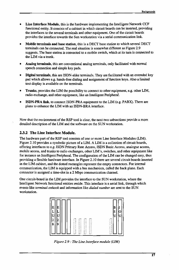
2.3.2 The Line Interface Module.The hardware part of the RSP tool consists of one or more Line Interface Modules (LIM).Figure 2.10 provides a symbolic picture of a LIM. A LIM is a collection of circuit boards,offering interfaces to e.g. ISDN Primary Rate Access, ISDN Basic Access, analogue access,mobile access, and trunks to radio exchanges, other LIM's, switches, and other equipment likefor instance an Intelligent Peripheral. The configuration of the LIM can be changed easy, thusproviding a flexible hardware interface. In Figure 2.10 there are several circuit boards insertedin the LIM cabinet, and the dotted rectangles represent the empty connectors. For internalcommunication, the LIM is equipped with a bus mechanism, called the back plane. Eachconnector is assigned a time-slot in a 2 Mbps communication channel.
One circuit-board in the LIM provides the interface to the SUN workstation, where theIntelligent Network functional entities reside. This interface is a serial link, through whichevents like terminal onhook and information like dialed number are sent to the SUNworkstation.
,.... - r- - r- -E E B IL 1.J S 0U U U U2 2
,"
f1,"
il,", ' · . , .· . , .
, ' , . , ., . , ' , .8 9 ' . , . , .
, . · ., . , . · . , ., . · . . '· '. ., .
, ' · '' ., ' , ., . · ', .
, ' · . , .- - .... - ." ..' ·".,' .,' .... ....
Figure 2.9: The Line Interface module (LIM)
17

An Intelligent Peripheral in the Intelligent Network
2.3.3 The software
This subsection provides an overview of the (Erlang) software running on the SUNworkstation. It describes the most important processes used by normal call processing andservice call processing.
2.3.3.1 Normal call processing
Figure 2.10 depicts a situation where two digital telephones are connected to a digital terminalinterface circuit board in the LIM cabinet. To receive signals from and to send signals to thehardware boards each board in the LIM has an erlang-process controlling it. In Figure 2.10,this is indicated with the circuit board controlling (C.B.C) processes. These processes receivebit-streams from and send bit-streams to the hardware boards.
The lim_driver process coordinates all these processes: it knows which process is controllingwhich board and it receives the signals from the boards via these processes. Lim_driverencodes and decodes the bit streams to messages and the other way around, respectively.
For each terminal connected to the LIM a process is running which controls the state andactions of the terminal. For a digital terminal this process is called dts (for digital trunk server).
Workstation •.. .
SSF
~ 1111 IMI ;1--__....1..
~ ..
.. _--- .. - ... __ .. _-.··'2·
r-- ...... ----·---· .. --· ........ --- .. --·.---. .
Figure 2.10: Normal call processing
In Figure 2.10 user 2 is off-hook. This is detected by the digital terminal's interface circuitboard and the an event off-hook is sent to the lim driver process (via the LIM's I/O unit andthe serial link). The lim_driver process sends this message to the circuit board controller,where the message is translated to a format understandable by the other processes. The circuitboard controller will notify the process dts(2) of the off-hook event. This process requests themaster-origcall process (not depicted) to create an originatin~basic3all_state_model (0BCSM), origcall(2) for the incoming side. This process will be started together with anssf50(2) process. This ssf50(2) will play an important role in the next subsection, where aservice has to be invoked. For now it is enough to know that it supervises the state-changes ofthe origcall(2) process. If the origcall(2) process reaches state 'call-proceeding' the processwill request the master-termcall process to start a terminatin~basic_calCstate_model for user1. This termcall(1) process will be created together with a ssf50(1) process, which will becomeimportant in the next subsection. If everything proceeds normally the switch circuit board(BSU) in the LIM will be instructed to set up a speech connection between the two terminals.This will be maintained until one off the terminals goes on hook or until one off the BCSM'sreach the 'exception' state.
18

-.
Backgrounds
Once again it is noted that only the important processes are mentioned here. In the nextsubsection four other processes will be introduced which run in the SSP. They are used todetermine that a service in the SCF has to be invoked.
2.3.3.2 Service call processing
The previous subsection described the SSF actions required for normal call processing. Thissubsection describes the service related call processing. Only the processing for the originatingcall-party is taken into account (originating side service processing). For the terminating callparty the same processing procedures apply (terminating side service processing).
Before the service call processing is described, it is required to know something about themechanism used for communication between SSF and SCF. This is called the breakpointmechanism. It allows the SCF to monitor state changes (events) in the BCSM. To receive anotification of a certain event, the SCF can subscribe to a breakpoint. There are two kind ofbreakpoints, which are listed below.
• Static breakpoints (in IN-terms Trigger Detection Points: TOP), used to check ifinvocation of a service is required. These static breakpoints are equal to the BCSM states,e.g. Collecting Info, Analyzing Info, Waiting For Answer.
• Dynamic breakpoints (in IN-terms Event Detection Points: EDP), used to monitor the useron certain events during a call. These breakpoints are used to influence the execution of theservice logic. Examples of this kind of breakpoints are : hook-flash and on-hook.
After a static breakpoint is encountered and reported to the SCF only dynamic breakpoints aredetected by the SSP. So it is impossible to have the call controlled by more than one service.Only after call control is returned to the normal call segment (i.e. IN service processing isended), a new static breakpoint can be detected and a new service can take over the call control.
Figure 2.11 again depicts the processes as described in the previous subsection As stated in theprevious subsection, the ssf50 process plays an important role in the service invocation. Theprocess controls the state changes of the BCSM's. Before each state transition in theoriginating BCSM, represented by the origcall(2) process, the ssf50 process checks whetherservice invocation is required. The process which keeps control of the breakpoints is called the(originating) static breakpoint server. In Figure 2.11 also the terminating static breakpointserver is depicted. This process takes care of breakpoints in the terminating BCSM. Thismakes it possible to provide terminating side service processing.
In the SCF three important processes are always running. The limyadJO acts as a protocoladapter towards the SSP. It receives all messages from and sends all messages to the initiatingssf50 process. The scfJ0 process is the main process, for every service relation, it spawnsseveral other process. Finally, the pdbJ0 process acts as an interface to the database, where theservice logic and service data reside.
19

An Intelligent Peripheral in the Intelligent Network
SCF
.............................
SSF
.. .. .. .. .. .. .. .. .. .. .. .. .. .. .. .. .....,............... __ .. ·I Workstation •
" __ __ __ _ • .1
Figure 2.11 : SSF part ofservice call processing
If the origcall BCSM process executes a state transition on which a (static) breakpoint is set,the ssf50 process is notified. It will gather the data associated with this breakpoint and it willsend an initiate message to the SCF. The ssf50 creates an originating dynamic breakpointserver to detect dynamic breakpoints during service execution. This is depicted in Figure 2.12.
·········• Workstation •.. __ ._ __ -. __ _ ~
SSF
SCF
'--__--I,........... __ .... _--
.....................................·.................. :···: I
··Figure 2.12 : SCF part ofservice call processing
In the SCF a service relationship is initiated on reception of the initiate message which initiatesthe processing in the SCF. Then a provide message from the ssf50 process is received, which
20

Backgrounds
contains all data associated with the breakpoint. This message is forwarded to the scfJ0process. This process creates a handlerlO process, which at its tum creates afspiJO process(flexible seIVice profile interpreter). This process reads the seIVice logic from the database andinterprets it. Then it takes the appropriate actions, defmed by the seIVice logic and the seIVicedata.
During the execution of the seIVice logic, events can be created (Le. operations to send to theSSp). The handler process collects these events and sends them to the scfJ0 process. Via thelim"'pad]0 process these events are sent to the appropriate ssf50 process, which takes thecorresponding actions. This process also sends an event message to the SCF if a dynamicbreakpoint is encountered in the originating BCSM (origcall). The only way the seIVicerelationship can be ended is by sending a transfer message from the SCF to the SSF. Onprocessing this message, the SCF and SSF kill the appropriate processes. Normal callprocessing resumes and static breakpoints will be detected again.
2.3.3.3 Non call reloJedfunctions
Next to the software representing the SSF and SCF functions, the RSP tool also includesrepresentations of the functional entities NMF, SMF, SDF and SCEF. These entities are of lessinterest because they are non call related. The list below gives a short description of theseentities.
• Network Management Function, needed to manage the several IN Network Elements. EachNetwork Element can include several Functional Entities. The NMF is aware of the statusof each of these Functional Elements (e.g. node down, active, stopped). The NMF is builtup out of two parts: the user-interface and the NMF-Kernel. The kernel consists of anNMF-application layer, used to adapt the kernel to different users, and an NMF-core layer,implementing the main functions of the NMF.
• SeIVice Management Function, which allows the user to install, re-install, de-installseIVices and to set triggers and trigger-conditions to allow users to use the installedseIVices. •
• SeIVice Data Function. This is the functional entity where the several types of data arestored. This includes SeIVice Logic, SeIVice Data and user data. The SDF consists of twoimportant processes: an interface process through which the other functional entities canaccess the main database process which contains the real database functions (e.g. put, get,show, erase).
• SeIVice Creation Environment Function. This is the environment where the seIVices arecreated. In the RSP-tool environment this functional entity is called the SeIVice Builder. Itprovides the user with a graphical environment, where SIB's (Control Types) can bepicked out of a library and connected to each other.
The description of these entities concludes this section about the RSP tool. The RSP tool willbe used to interwork with the IP which has to be developed. The implementation of the IP andthe results of the integration in the RSP tool is described in chapter 6 and chapter 7.
2.4 Specialized Resources.This subsection gives an introduction in the area of specialized resources in the telephony field.It describes several aspects of these resources. This includes the quality of seIVices that users
21

An Intelligent Peripheral in the Intelligent Network
experience, the integration of new media types, the introduction ofnew techniques, and networkaspects like delays, traffic and distribution of intelligence. Most of these items will be describedmore specific in the subsequent chapters.
Next to these general aspects this section describes the resources available for the IP that has tobe developed.
2.4.1 General aspects
In this subsection some general aspects on specialized resources in telephony networks. Theseaspects are important to keep in mind during development of an Intelligent Peripheral, and theywill therefore return in the subsequent chapters of this document.
2.4.1.1 Introduction
In the early days of telephony the main specialized resources were human resources. Users ofthe plain telephony service frrst had to connect to the operator, after which they whereconnected to the other party. Later this operator function was taken over by first 'dumb' andlater 'intelligent' switches. However, there are still many human resources in the telephonyservices of today, just think of the number information service provided by telecom operators.Next to these human resources the telecom operators use more and more sophisticatedequipment to provide their customers with the information they are looking for. Examples ofthis information services are : weather forecast services, time service, and various amusementservices.
The Intelligent Network concept provides the operators with the possibility to enhance thenumber and complexity of the services. The main characteristic of the new services is theirinteractive behavior. In stead of listening to the weather forecast service as one long message,the user can guide himself through a menu to just obtain the information he wants to hear andskip the rest. A shop can allow its clients to order products by phone just by pushing theappropriate digits on their telephone sets.
2.4.1.2 Quality ofservice.
The perceived quality of the services offered by a telecommunications company, and therebythe perceived quality of that company is, in part, derived from experiences which customershave when using or encountering voice services. In particular, such perceptions tend to bebased upon the ease of use and naturalness of these services. As such, it is important that voiceautomation and voice services are used in appropriate circumstances and are designed andstructured so as to improve perceptions rather than lower them.
In many cases, given the choice of interacting with a person or a machine, callers would notchoose to interact with an automated service. An illustration of this is the response which manypeople have when confronted with an answering machine. In some cases, the caller will simplyhang-up and not leave a message. As the caller may be disappointed at not having made directcontact with the person they have called, this behavior is accepted, but is difficult to explainrationally. In addition, the owner of the answering machine has installed the answering machinenot only for their own convenience but also for that of the caller. This demonstrates theimportance of the quality of the user interface provided by voice services.
2.4.1.3 New media
While traditional IN services require a fairly "dumb" resources for announcements andinteractive dialogues with users, the resources are becoming increasingly intelligent. The IN
22

Backgrounds
architecture and concept developed for narrow-band services may also be capable ofsupporting broadband applications, such as video-on-demand. Also integration of data services,such as E-mail, and voice services, such as voice-mail is possible in the IN architecture. Thisintegration of new media in the telephone network puts additional design-requirements on theIP.
2.4.1.4 New techniques.
To make optimal use of the development of new resources requires a well-structured designedIP and well-defmed interfaces. To give an impression of the fast evolution of the resources afew examples are described below.
• Playing of speech: The sending of speech towards users was fIrst accomplished byconnecting the user to a human operator. This was taken over by the use of announcementequipment. First these machines used magnetic tapes to playback earlier recordedmessages. Nowadays there is an extensive use of digital techniques. The messages aresampled and digitized, after which they are stored in RAM or ROM or at fast magneticmedia like hard disks. At this moment the possibility to use speech synthesis isinvestigated.
• Recording of speech: Just as the sending of speech to users the receiving of speech fromusers was fIrst accomplished by human operators. Later the use of magnetic tapes tookover, enabling the well known voice mail services and answering machines. At the momentthe recording of speech is often accomplished by sampling and digitizing it and store it inRAM. Research is focused on automatic speech recognition, after which the recognizedspeech can be StOled using digital media or can be used in interactive services.
• User interaction: For many services there is a need for user interaction. This can of coursebe accomplished by connecting the user to a human operator. Often this solution is notinteresting, because of the relative high costs. Therefore often the telephone keypad is used.The key-presses, converted to DTMF signaling signals can be automatically detected. Thelimited number of keys (often 12 buttons) on the conventional telephone sets limit thepossibilities for the user interface. Digital telephones (ISDN) are therefore equipped withspecial menu-buttons, to which functions can be assigned. Next to these function-keysthese telephones are facilitated with LCD text displays. At this moment research focuses ongraphical user interfaces towards users of wireless terminals. These are equipped withtouch screens, thus eliminating the need for normal press-buttons.
• Conversion of media: To integrate the use of various media types (i.e. pronounce areceived E-mail to the user) there is need for conversion. Examples of these conversions arealready mentioned above, think of speech recognition and synthesis. With the integration ofthe computer world and the telephony world conversions like E-mail to fax, postscript tofax and the other way around are needed. With the introduction of broadband applications(video) exotic conversions like video to fax and html to video become interesting.
The above mentioned list gives an impression of the possibilities of the functionality ofresources. The prototype IP as it will be developed will include some of the mentionedfunctions. These functions will be accomplished by a combination of hardware boards andsoftware tools. The second section of this chapter describes the used resources.
2.4.1.5 Network aspects
To make optimal use of the capabilities of the special resources, it is important to optimize theconfIguration of the special resources in the network. The Intelligent Network recommendationQ.1205 allows two physical confIgurations (regarding position of SRF):
23

An Intelligent Peripheral in the Intelligent Network
1. Integrated SRF. The SRF can be integrated with SSF and CCF in a Service SwitchingPoint, or even with the SCF, SDF, SSF, and CCF in a Service Node.
2. SRF in Intelligent Peripheral. In this case there is a complete physical separation betweenthe SRF and the SCF and SSF.
The advantages of the second option are listed below.
• Effective use of resources:
Using separate IP's allows some systems to be dedicated to some type of dialogues. Theresources can be shared by more than one SCP, increasing the efficiency of these resources.
If the SRF is integrated in the SSP, each SSP must support all the possible dialogues. Inaddition, the number of resources on each SSP has to be scaled to the network demands duringthe busiest hour on the busiest day.
• Maintenance and Operation,
Maintenance and operation of separate IP's is easier than with integrated systems, as they canreside in a single location, independent of the other network elements.
For example, in case of an integrated SRF, updating the user-dialogues (e.g. voiceannouncements) involves accessing all the network SSP's. In case of the separate SRF, onlythe IP has to be accessed.
• Network delay's
Separating the SRF from the SSF causes an increasing use of signaling traffic. This can resultin network delays, thus decreasing the quality of the service experienced by the user. Byincreasing the number of separate IP's in the network, this problem can be minimized.
Another way to decrease the amount of signaling traffic, is to distribute the IN Service Logic.When a service requires the user to browse through a menu, each step can be coordinated bythe SCP, but it is also possible to let the IP control the complete menu processing. The SCPonly initiates the menu processing and gets the result from the IP when further SCP processingis necessary.
• Network load
In the case of a separate IP, accessing IP resources involves telephone line switching, whichmay become network resource-consuming. Integrating the IP in an SSP has the advantage ofminimizing the use of the telephone network resources, when voice processing capabilities arerequired for dealing with a call.
• Defmed interfaces
An advantage of a separate SRF is that the interfaces to the resources are well defmed. Thisallows keeping the development of special resources separate from the other aspects, e.g. thedevelopment of switching-equipment and service-building. Therefore the telecommunicationcompanies can profit from fast evolving technology, especially in the electronics and computerfields.
Also the voice dialogues for performing operations, such as collecting a PIN code or a callednumber, can be worked on by people other than the person in charge of designing the INservice in which these operations are requested.
24

Backgrounds
Considering these aspects, one can conclude that implementing the SRF as a separate networknode, the IP, is a good option. The impact of some of the aspects mentioned above on theimplementation of the IP will be one of the subjects in the subsequent chapters in thisdocument.
2.4.1.6 Summary
In this subsection several aspects of resources in the telecommunication were described. Theimplications of these aspects are summarized below.
The ever increasing demand of (voice) resources and the increasing complexity of the servicesdemanding the resources require a flexible way to adapt the number and functionality of theresources in the network.
The quality of service is an important factor in the customers satisfaction. This quality ofservice will for a great deal determine the success of the service. It is therefore important to beable to improve the resources in the network as fast as possible.
Integration of new media in the telephony network opens doors to a big variety of newpossibilities. The resources in the network have to be prepared to participate in this integration.This puts a requirement on the flexibility of these resources.
To make optimal use of the fast evolution of techniques the design of the IP has to be asgeneric as possible. The interfaces has to be standardized, so that new resources can beintegrated without problems.
Deliberating network aspects like maintenance of resources, network load, network delays, anddefmed interfaces, the implementation of a separate IP is to be recommended. Of course thisoption has some drawbacks, but these can be minimized by taking them into account during thedevelopment of the IP.
2.4.2 Available resources
The IP prototype has to be implemented in a LIM cabinet. This LIM cabinet is describedbefore in section 2.3.2. It consists of a number of slots, which are all connected to a PCMcommunication bus. New hardware can be add to the IP by plugging a board in the LIM andupdating the software that controls this hardware. For the implementation of the IP prototype anumber of hardware boards are available, which are described below.
• DTMF receiving:
A possibility to guide the user through a menu is by means of the telephone keypad. The keyson the keypad are coded as DTMF (Dual Tone Multi Frequency) tones. These are sent throughthe telecommunication network as in-band signals. To receive these DTMF tones a ToneReceiver Unit (TRU) is available. This TRU consists of a mother board, where an analyzeprocessor (68000) and a serial channel processor (68121) are placed, and a daughter boardwith logic for fIlter calculation.
The signal interface contains operations for activation of the board, board identification, tonedetect requesting, test-program requesting, tone detect result transmission, and so on.
• DTMF and tone sending:
One way to give the user information on the status of the service is by sending tones throughthe speech channel. The hardware to do this is the Tone Sending Unit (TSU). This is a digitaltone generator, which generates sequences of PCM samples. It can generate in-band signaling
25

An Intelligent Peripheral in the Intelligent Network
tones (e.g. busy tone, congestion tone, ringing tone). It can also generate key-code digits tomimic a real DTMF telephone.
The signal interlace contains operations for board activation and identification, tone sendingrequests, and changing the frequencies and cadences of tones.
• Speech recording and play-back
To provide the user with a good user-interlace, the playing of speech towards the user isessential. Next to the playback of speech, the possibility to record speech creates the possibilityof voice-mailbox applications. The hardware available for these tasks is the Voice Server Unit(VSU) board, which is designed with the Signal Processing Unit (SPU) as a base. The VSUincludes a number of basic functions as recording, playing, copying and backup of speechmessages. The speech messages are stored as fIles at the board, on the battery backed up RAMdisk.. controlled by the VSU fIle system. To increase the storage capacity, the speech messagesare stored in a compressed form and the Expanded Memory Unit (EMU) is mounted as a subboard on the VSU.
• ISDN ASCII text capabilities
When a user has access capabilities to the ISDN network, it is also possible to send and receivetext messages through the ISDN D-channel. These messages can be used to enhance the userinterlace with text facilities, thus decreasing the importance of the audible interlace. These Dchannel capabilities are provided by the ISDN PRA interlace board as described below.
• ISDNPRA:
The circuit board TLU76 is a digital trunk line device board, designed to provide layer 1 andlayer 2 of the ISDN Primary Rate Interlace. The main function for TLU76 is to connect a 30channel PCM link to the LIM-switch. The LIM interlace occupies 32 timeslots of which 30 areused. The board contains a processor-part with programs to support different types of Dchannel protocols (providing the text capabilities described above). A conversion is perlormedon the board between the LIM signal format and the format of the link protocol.
• Other resources.
Next to the hardware described above also the hardware connected to the UNIX platform canbe used to implement the IP. For example, to enhance the IP with E-mail facilities, connectionto the Internet is necessary. Another possible application area of the UNIX platform are thespeech synthesis capabilities of this system. The UNIX platform will also be used to control thehardware in the IP. Connection of the UNIX platform to the LIM hardware is possible via aserial interlace. In the LIM this interface is provided by a hardware board called the 110 Unit(IOU).
2.5 ConclusionsThis chapter gives the user some background information, which will be used in the remainingpart of this document.
The first subsection discusses the Intelligent Network concept as described in the lTV andETSI standardization documents. The conceptual model describes the IN on four abstractplanes, the service plane, the global functional plane and the physical plane. The description ofthe IN concept provides the basis information needed to the research of the SRF.
The second subsection describes the Ericsson implementation of the Intelligent Networkconcepts. It covers the analogies to and differences from the standardized IN concept, anddescribes the service-creation and management system SMAS.
26

Backgrounds
The third subsection describes the Rapid Service Prototyping (RSP) environment in which theprototype IP has to be integrated. Both the hardware and software of this RSP tool aredescribed and the processing of normal and service calls is worked out. The integration of theprototype IP in the RSP tool will probably not demand big changes in the existing RSP tool.
Some general aspects of special resources in the telephony network are covered. Distributionof intelligence, network aspects, integration of new media, use ofnew techniques, and qualityof service are described. These aspects are important to keep in mind during development of theIP and some of them will therefore return in the remaining part of this document.
27

3. Functional asp_ec_t_s_. _This chapter covers the functional aspects of the Intelligent Peripheral. The first subsection describesthe functional requirements of a generic IP. This includes resource requirements, managementrequirements and service processing requirements. The second subsection describes the functionalrequirements of the prototype IP. First it defmes a benchmark service, P-mail, after which it deducesthe requirements that the benchmark service puts on the prototype IP. Finally, this chapter describesa functional model of the prototype IP.
3.1 Functional requirements of a generic IP.This subsection describes the functional requirements of a generic IP. The ITU standardizationdocuments are the basis for the determination of these requirements.
The functional requirements can be split up in three parts. The resource requirements defme thebasic functionality that the IP has to provide to the services. They defme the capabilities asthey are experienced by the users of the services.
The management requirements defme the IP's capabilities towards the network operatorconcerning installation, operation, maintenance, and administration aspects. The managementrequirements can be split up in service management, covering the installation and maintenanceof the services offered to the users, and network management, covering the networkconfiguration aspects.
The service processing requirements defme in what extent the IP has the capabilities to carryout tasks. The advantages and drawbacks of the distribution of logic between the SCP and IPare described. Also the capabilities to process a number of calls simultaneously are defmed bythe processing requirements.
3.1.1 Resource requirementsThe Intelligent Network Physical Plan architecture [Q.1205] states that the IP provides specialresources for customization of services, and supports flexible information interactions betweena user and the network.
The IP contains the SRF, and optionally a SSF/CCF. This optional SSF/CCF is used toprovide external access to the connections to the resources within the IP. The IP connects toone or more SSP's, and/or to the signaling network. An SCP can request an SSP to connect auser to a resource located in an IP that is connected to the SSP from which the service requestis detected. An SCP can also request the SSP to connect a user to a resource located in an IPthat is connected to another SSP.
According to the Intelligent Network Distributed Functional Plane description [Q.1214] CS-lsupports the following special resources:
• DTMF digit collection, this resource receives Dual tone Multi-Frequency (DTMF) from auser, and recognizes it as a standardized signal input;
• tone generator, this resource provides a user with in-channel tone-information (e.g. busy,unknown number, dialtone);
• customized and concatenated voice announcements, this resource sends pre-defmedannouncements towards a user (e.g. "The number you dialed is not reachable", or "Yourcall lasted three minutes and thirty seconds");
29

An Intelligent Peripheral in the Intelligent Network
• message sender/receiver, this resource sends or receives messages, such as electronicmessages, voice messages, etc., to/from users.;
• synthesized voice/speech recognition devices with interactive prompting facilities, thisresource receives in-channel speech information from a user, and recognizes it as astandardized signal input. The resource recognizes the information and converts it to INperceivable signals. When the resource receives an instruction to send a voice message, itconverts the information in this instruction to a voice message.
The following special resources are planned for use in future capability sets:
• audio conference bridge, receiving in-channel audio information from any other linkedresources, this resource mixes this information and sends the mixed information to all thelinked resources;
• information distribution bridge, receiving in-channel information from a linked resourcethis resource distributes the information to all the other linked resources. This resource isused as an information broadcasting device;
• text to speech synthesis, this resource receives text messages (sent through e.g. ISDN Dchannel or ADSI protocol), converts these messages to in-channel speech information andsends them to a linked resource;
• protocol converters, this resource receives messages of several formats (yet to be defmed),converts them to other formats (e.g. text to fax), and sends them to a linked resource.
3.1.2 Management requirementsThe management aspects of IN can be summarized as the management of service and networkfunctions. Managed objects are very diverse. They can be divided according to their logical,functional, and physical nature. Examples of managed objects include: services, serviceindependent building blocks, trigger table data, network services (i.e. LAN,ISDN), resources,connections and calls.
To manage all the different kinds of managed objects, integration of the IN architecture andTMN concepts is an important issue. The integration of TMN and IN has been investigated inseveral ITU-T and ETSI projects, which are summarized in [Kockel].
One of the outcomes of this integration will be the identification of IN specific managementrequirements concerning the deployment, provisioning, control, monitoring and billing/chargingof services. These requirements contain amongst others configuration, performance, fault,accounting and security aspects.
Because of the vast programmability possibilities of new services, the IN long-termarchitecture should also support the ability to program (in parallel with the service processinglogic) management logic. To accomplish this, management SIB's may be provided.
3.1.2.1 Service Management
Network requirements for service management refer to the network capabilities that arenecessary, from a network operator point of view, to support the proper operation of services[Q.1201]. The management capabilities can be defmed for three different phases in a servicelife cycle:
• Service management during deployment phase.
30

Functional A!illffiS
This activity requires first a limited deployment of selVice for testing purposes. If testing issuccessful follow with:
• downloading of selVice logic (if using distributed logic, e.g. selVice specific IPscripts, as described in section 3.1.3.1) into the IP, and
• activation of this logic in the IP.
• SelVice management during provisioning phase.
This involves such activities as the creation of the customer's selVice prof1le in the selVice logicand the activation of the selVice for the customer. This may require the initialization of triggerconditions in the IP (for IP initiated selVices, e.g. notification of arriving message) and thecreation of the customer's selVice prof1le in the selVice logic.
• SelVice management during utilization phase.
• SelVice control gives the customers the ability to modify parameters which controltheir selVice. This could include, for example, screening lists or rules fornotification of arriving messages dependent of time of day and/or day of week.
• Data entered by the customer must be validated to ensure that, for example, thecustomer has the permission to change the indicated parameters and that theparameters, as modified, are valid.
• Under IN, there may need to be several kinds of charging schemes, e.g. flat rateand usage sensitive. The usage sensitive charging may consider not only theduration of a call, but also the IP-resources required to provide the selVice. In thislatter case, the tariff may be "selVice independent" in the sense that it is computedfrom the cost of the IP-resources used rather than from the value to the customerof the selVice offered.
3.1.2.2 Network Management
IP requirements for network management refer to the IP capabilities that are necessary, from anetwork operator point of view, to support the proper operation of the IP.
The IN and non-IN requirements of network management are not essentially very different. TheTMN (Telecommunication Management Network) application functions are relevant to IN asmuch as they are to non-IN. Therefore, the following organization of management capabilitiesregarding the Intelligent Peripheral are applicable ([Terplan], [M.3400]):
• performance management, provides functions to evaluate and report the behavior andeffectiveness of the IP :
• performance monitoring, e.g. the mean resource access time, the number of refusedrequests;
• traffic management and network management, e.g. dynamically change thefunction of multi purpose resources if they are not used frequently;
• quality of selVice obselVations, e.g. the audibility of the announcements, thecorrect decoding of digits, and the correct recognition of speech;
• fault management, provides functions which enables the detection, isolation and correctionof abnormal operation of the IP :
31

An Intelligent Peripheral in the Intelligent Network
• alarm surveillance, e.g. the IP reports a failure in one of the resources;
• failure localization, if the infonnation in the IP fault-report is insufficient,additional procedures are available to locate the failure;
• testing, e.g. the network operator can request the IP to (self-)test its resources;
• configuration management, provides functions to exercise control over, identify collect datafrom and provide data to the IP :
• provisioning, e.g. to bring the IP into service after it has been installed or to infonnit about the status of other Network Elements;
• status and control, e.g. to monitor or change the status of the IP or one of its subparts (in-service, out-service, stand-by);
• installation, e.g. to support the installation, extension, or reduction of the IP, or toinstall new software (e.g. new speech recognition library);
• accounting management, provides a set of functions which enables the use of the IP to bemeasured and the costs for such use to be determined;
• security management, provides functions to protect the IP against unwanted access byusers of the IP functionality (e.g. which users may read/write/delete stored messages).
3.1.3 Service processing requirementsThe service processing requirements defme the processing capabilities of the IP. An importantaspect is in what extent the IP has the capability to execute (user-interaction) scripts. Thiscapability implies the distribution of logic between different physical entities. The firstsubsection uses the example of a credit card validation dialogue [Bic] to describe the idea ofthe distribution of logic and to identify the expected problems. The second subsection coversthe multi-call processing capabilities of an IP. Finally, the last subsection defmes a functionalmodel for the generic IP.
3.1.3.1 Distribution oflogic
This subsection describes the possibility to distribute the processing of a service between theSCP and the IP. This distribution of logic is explained using an example, a credit-cardvalidation user-interaction [Bic].
The lTV and ETSI standardization currently recommends that the IP is fully driven by an SCP,that is, the SCP has the full responsibility of conducting the voice dialogue with end users. Thisis depicted in Figure 3.1.
32

SCP IP SSP
Functional Aspects
End user,,,,,
lnitialDP,
· ·, ·, ·, ·· ,· ,· ,
ConnectToResource · ,···
SebJp
E-------~---~AssistRequestlnstructions
,,···PlayAnnouncement ·Play greeting message:-------,-----11
PromptAndCollect,
~~p!!o~~ ~m~~ ___ ~
·Result:P&C f- ____~11~~£~.Ei£ts_
,,
PromptAndCollect ,Prompt for PinCode '-------:----~·
Result: P&CCollect DTMF Digits
f- - - - - - -:- - - - -
DisconnectForwardConnection
Disconnect
E------- ----~
User makes service call
SSP recognizes call and requests service in SCP
Service Logic detects need for user interaction
SSP sets up bearer connection
Bearer connection between IP and and user active
IP requests SCP for instructions..,
: • •SCP dictates user interaction
• J
SCP orders disconnection of IP
SSP disconnects IP from end user
Bearer connection between IP and and user released
Figure 3.1 : Signal diagram when the all the logic resides in the SCP
In the picture the physical entities in the Intelligent Networks are depicted next to each other.The vertical lines indicate the time, and the arrows indicate messages transferred betweenphysical entities, or actions carried out by these functional entities. The names of the messagesare not exactly according to standardization documents.
When a user dials a telephone number that needs service processing, the SSP requests theservice from the SCP by sending an InitialDP message. This message contains informationfrom the end user, on which the SCP can determine which service is required. In this examplethe service requires credit card validation of the end user. The SCP request the SSP to connectthe end user to the IP. The SSP sets up a speech connection between the user and theappropriate resource in the IP. Next the IP sends an AssistRequestInstruction message to theSCP, after which the SCP will start the required user interaction. In this example the userinteraction starts with the playing of a greeting message, after which the user is prompted toenter his credit card number. The result of the user actions, the received digits, are returned tothe SCPo The SCP then orders the IP to prompt the user for his PIN, and receives this PINfrom the IP after the user has entered it.
Finally the service logic in the SCP orders the SSP to release the speech connection betweenthe user and the IP, and service processing continues.
33

An Intelligent PeriPheral in the Intelligent Network
The distributed functional plane [Q.1214] defmes that the SRF 'may contain the logic andprocessing capability to receive/send and convert information received from users'. Thisrecommendation leaves some room for extension of the processing capabilities of the IP.
The idea of the extension of the processing capabilities is depicted in Figure 3.2, again usingthe credit-card validation user-interaction.
SCP IP SSP End user····· InitialDP·· ·· ·· ·· ·· ·· ·· ·ConnectToResource · ····
Setup
AssistRequestInstructions~------~---~
···RunScript
~aLgr~~g~~!: ~____ ~
~~p;!o!:..ca~~m~____ ~
·~ ____~1~£T~.E~ts_
···~~p;!o:!~c~_:____ ~
·Result :Script~ ____ ~1I.:.:!£T~.E~ts_
DisconnectForwardConnection
Disconnect
E------- I----~
User makes service call
SSP recognizes call and requests service in SCP
Service Logic detects need for user interaction
SSP sets up bearer connection
Bearer connection between IP and and user active
IP requests SCP for instructions
: • •IP dictates user interaction
SCP orders disconnection of IP
SSP disconnects IP from end user
Bearer connection between IP and and user released
Figure 3.2 : Signaling diagram ifthe logic is distributed between SCP and IP
The procedure for the setup and the release of the connection between IP and user is the sameas described in the example above. The main difference is that the user-interaction logic staysin the IP rather than in the SCP, so the logic is distributed between two physical entities. Instead of ordering the IP to playa single announcement or to receive a number of digits, theSCP now orders the IP to run a complete logic "script". In this case the script only consists ofplaying one announcement and prompting the user to enter digits two times, but the scripts canbe much more complex.
After the IP concludes the script it sends the result of the script (in this case two 4-digitnumbers) to the SCP, which further interprets the data, and continues service processing.
Of course the script logic for the distributed processing has to be present in the IntelligentPeripheral. If it receives a request to run a script, and the script logic is not present, it has torequest the SCP to download the necessary data. This SCP-controlled downloading of scripts is
34

Functional Aspects
not described in the standardization documents. However, the power of this concept is very big.It creates the possibility to use very specialized (third party) IP's.
Next to the script logic, also subscriber data like user proftles must be downloaded in the IP. Ifthe IP changes this data, it has to be updated in the SCP (assuming the SDF is integrated in theSCP) after fmishing the execution of a script.
The distribution of logic has advantages and drawbacks, which are described below.
Advantages of distributed logic :
• It is clear that the amount of traffic between SCP and IP is much lower when distributionof logic is used. In practice the decrease of traffic will be even more drastic as describedabove, if the error handling (e.g. a user pressing inappropriate digits) is processed in the IP.Of course the amount of data to be send in one message is greater in the case of distributedlogic, but because of the message overhead, the total amount of traffic on the signalingnetwork will decrease significantly.
• Another important advantage of the distribution of the logic is the faster response of the IPresources towards the users. In the example the time between entering the credit-cardnumber and the prompt for the PIN will be reduced by the time needed for the transmissionof the ResultP&C and PromptAndCollect messages. This reduction increases the qualityof service experienced by the user.
• The distribution of logic separates the developing of dialogues and other user-interactionsfrom the developing of real IN-services. This makes it possible to isolate the userinteraction aspects of a service for the developers of services. The service developerdoesn't have to care about error handling, e.g. a user entering an erroneous digit, or a userwaiting to long before entering a digit.
• The distribution of logic makes it possible to spread the processing load over severalphysical entities in the Intelligent Network. This is especially interesting for veryspecialized activities or activities which consume much processing time.
Drawbacks of distributed logic :
• In the example above the IP processing restricts to the user interaction. Distribution can beextended to the case that the IP also validates the entered credit card number and PIN. Thisstep introduces another important aspect of distribution: the distribution of data. Datadistribution makes the system more complex, and management of the data is veryimportant. Also security has to be guaranteed, which makes the system even morecomplex. Finally, excessive data transfers can even cause congestion on the signalingnetwork. This, together with the fIrst mentioned advantage about the decrease of networktraffic, indicates that an optimum exists for the extent to which a service is distributed.
• Next to the increased complexity caused by the distribution of data, also the managementof distributed logic is more complex, this includes installation and maintenance of thescripts in the IP's in the network. To keep management of the distribution possible, thedistribution of logic must be restricted to local tasks; the network wide view should bemaintained by the SCP, the IP only relates to the SCP and the user.
• Finally the interfaces towards the IP become wider if it is capable of executing scripts. Ifthe SCP wants to execute a certain script in an IP, it has to send a script-identifier, whichhas to be the known in and unique to all the IP's that can be used by that SCPo To becompliant to the standardization the IP must at least have the processing capabilities to
3S

An Intelligent Peripheral in the Intelligent Network
serve the service requests defmed in CS 1 INAP [Q.1218]. Next to these capabilities theoperator can defme its own scripts in the IP, and the SCP can download scripts in the IP.
Considering these advantages and drawbacks, the distribution of logic is preferable. It raisesthe quality of services and increases the processing capacity of the network by reducing thenetwork traffic and distributing the processing across the network. To keep the complexity ofthe system as low as possible, it is recommended to minimize the use of distribution of data. Ingeneral it is recommended to keep the message related data, including voice and text storage(messages, headers, personal greetings) and status of messages, in the IP. To trigger a service asubscriber list has to be stored in the IP. Other data, like user profiles and passwords should bestored in the SDF, and should be downloaded in the IP if needed.
3.1.3.2 Multi-call processing
Another important processing requirement is the number of calls that can be handledsimultaneously by the IP. This number is limited by several factors :
• Number of incoming/outgoing lines
• Number of resources available
• Processing power of the software that controls the resources
• Signaling capacity between control software and resources
The scalability of the IP is an important factor. Therefore, during design of an IntelligentPeripheral, all above mentioned aspects must be taken into account. Increasing the number oflines and resources must be possible. The processing power of the control software and thesignaling capacity needed to control the resources must be prepared for this expansion.
To make optimal use of the resources the IP must provide the functionality to dynamicallyconnect resources to and disconnect resources from the incoming lines. These switchingcapabilities are not demanded by the ITU recommendation.
3.1.4 Functional model
The functional requirements as stated in the previous section lead to a functional model of theSRF. This functional model, depicted in Figure 3.3, is based on ITU-T document [Q.1224].The reason for the choice of this (yet unstable) CS-2 SRF functional model is, amongst others,the concept of User Interaction scripts, which is unknown in the CS-I SRF functional model.
36

Functional Aspects
RCP ResourceLogic Library
SRFResource I ResourceManager
I Logic Instances
WVI-scripts
TransactionModule
RFP DP
F I announcem. los manager
E Ivolce record. Irecorded v.
A IvOice racog. I sound
M 101 Mf collec. ! image
101 Mf defec. ! text
! text send/rec.!
· · · · ·· · · · ·· · · • ·· ,..;.. · .....................................................- .... I- - - --------------------· ·I ·· ............................. ""
· ·· ·· ·· I ·· I
· ·~SF/CCF I SMF
INMF
ISCF II Other
Access
---------------------------1
RCP: Resource Control Part •••••• Data/BearerRFP: Resource-Function Part Control/SignalingDP: Data PartFEAM: Functionality Entity Access Manager
Figure 3.3 : Generic IP functional model
The functional blocks in Figure 3.3 are described below.
The Functional Entity Access Manager provides the functionality necessary to exchangeinfonnation with other functional entities, the SSF, SCF, NMF, and SMF. It also provides thefunctionality to connect the SRF to non-telephony access, such as Internet and cable TV.Finally, it provides the functionality necessary to handle the bearer connections and to connectthem to the resources.
37

An Intelligent Peripheral in the Intelligent Network
The SRF Resource Manager (SRM) provides functionality's necessary for the SRF to managethe resources contained in it. The RM contains the capabilities to search for a resource, toallocate or de-allocate it, to manage the status of a resource and to control its actions.
The Transaction Module provides the functionality necessary for detection of transaction fromthe communication links and the routing of transactions to the right application scripts.
The User Interaction-scripts (VI-script) block provides to the SCF a vision of the differentspecialized resources that the SRF can perform. This block provides the capability to distributethe processing of a service between the SCF and the SRF.
The Resource Logic Library contains the SRF logic and indicates the physical resourcesnecessary for a given VI-script.
The Resource Logic Instances instantiates the SRF resources that are necessary for the correctexecution of the invoked specialized resource.
The Resource Function Part is a collection of resource-function pairs or functional elements ofresources. Resources in a resource-function pair for a service procedure are allocated andreleased together.
The Data Part is composed of the database-manager and the database, which contains recordedvoice, sound, text, etc.
The description of the SRF functional model concludes this subsection about functional aspectsof a generic IP. The next subsection describes the requirements of these functional aspects onthe prototype IP.
3.2 The prototype IPThe fIrst subsection of this chapter described the functional requirements of a genericIntelligent Peripheral. This description included management, service processing and resourceaspects. This second subsection describes the functional requirements for the prototype that isto be implemented. This prototype has to interwork in the RSP prototyping environment in theIN Application Laboratory, described in section 2.3. The functional requirements for the IPprototype are listed below:
• recording of speech• playing of speech messages (and voice prompts)• decoding of DTMF digits• generating ASCII text messages (e.g. to support voice prompts), through ISDN D-channel• reception of ASCII text responses, through ISDN D-channel• initiating a call towards a user• generating e-mail messages towards a user• reception of e-mail messages from a user (use as customer control)
To test whether the implementation meets this requirements a service is defmed, which coversall aspects of the requirements. The fIrst subsection describes this service, and identilles the IPfunctional requirements imposed by this service. The second subsection summarizes thefunctional requirements.
38

Functional Aspects
3.2.1 Prototype benchmark service
To test the implementation of the IP a benchmark service is defmed. This service uses all theuser-capabilities that are listed above. The service, called P-mail (phone-mail) providessubscribers with E-mail capabilities via the telephony network. The fIrst subsection provides adetailed description of the service. The subsequent subsections give an overview of therequirements that the P-mail service puts on the IP prototype. Finally, the third subsectionmaps these requirements on a functional model.
3.2.1.1 P-mail service descriptionThe benchmark service, P-mail, provides subscribers access to the E-mail facilities of theInternet. Internet is a worldwide computer network, providing access to information bases allover the world. E-mail, one of the most used application on Internet, allows users of computersystems which are connected to Internet to send messages to and receive messages from otherconnected users. The messages are normally text fIles, but any other information (such as voiceand graphics) can be attached to the messages.
The functionality of P-mail is twofold:
• Subscribers who normally have access to E-mail facilities via the Internet can use P-mail tohandle their E-mail on any telephone.
• Subscribers who don't have access to E-mail facilities at all can subscribe to the P-mailservice and can be provided with limited E-mail facilities.
These two options are described detailed below.
• P-mail users with access to Internet E-mail facilities.
A user who has access to normal E-mail facilities can forward his mail to the P-mail server,thus creating the possibility to "read" his E-mail via the P-mail server if a connection to theInternet is not available, e.g. a salesman at a client's office.
If a digital telephone terminal utilized with text-display is available, the user can read his mailon the text display. The SRF has to take care of the conversion to the correct text format. If ananalog terminal is available, the SRF has to convert the E-mail message to an audio-fIle whichcan be played towards the user.
Sending mail from a terminal can be achieved by choosing a destination out of a pre-defmedaddress list (see section Customer Control). The user will be prompted to record a message,after which the SRF will convert it to a audio-file which will be attached to a E-mail message.The E-mail message will be sent to the destination address. Also it is possible to defmestandard-messages (see section Customer Control) assigned to menu-items (see section UserInterface). If it is possible to enter text at a terminal, this can be used to edit a message andenter the destination address (virtual terminals in RSP-tool).
• P-mail users without Internet access to E-mail.
To non E-mail users, the P-mail service provides the operator with the possibility to act as Email provider. The features mentioned above are also available to these users. Only theCustomer Control has to be accomplished via the telephony user-interface.
The following Customer Control functions have to be provided :
• activate/deactivate P-mail service.
• create and change personal address list.
39

An Intelligent Peripheral in the Intelligent Network
• defme standard messages and replies (function keys).
• defme signature and header.
• defme VIP-list.
• change read/delete options.
• defme notification mechanism:
calion a specific number of arrived messages
call when mailbox full
never call
notification via indication-led (if present)
only notificate on arriving messages from VIP-list
The mentioned call control functions can be done via E-mail (or WWW-page). For P-mailusers who don't have access to Internet, the call control functions have to be done via theoperator.
A menu structure has to be provided to give the user the opportunity to control the P-mailservice using the telephone key-pad. The basic functions that have to be controlled are thesending, reading, and deleting of messages.
To indicate the functions of the several physical entities, depicted in Figure 3.4, a typicalscenario will be described now.
* : For clarity reasons only the connection to the IF is drawn
Figure 3.4 : Network picture for the P-mail service
Person X sends an E-mail message to P-mail user B. User B forwards all his incomingmessages to his P-mail address. When the message arrives at the E-mail acce~s in the IP, it will
40

Functional Aspects
be checked whether the destination address belongs to a P-mail subscriber. If so, the IP willrequest the SCP to start a service script. This service script fIrst checks the user-profIle ofsubscriber B (which resides in the SDP) whether it is desired to notify the user of the arrival ofa message. If the profIle states that notifIcation is desired, the script will carry out thenotifIcation, e.g. instructs the SSP to set up a voice connection between the IP and terminal A(which number is found in the user-profIle). The script in the SCP will then instruct the IP toconvert the E-mail message to the appropriate format (depending on the type ofterminal A) andto send the converted message to terminal A. Optionally in the IP a DTMF tone receiver islinked to the connection, allowing the user to control the service. The user can choose to replyto the message by pressing the appropriate key. This action is received by the DTMF tonereceiver and reported to the script in the SCPo The script instructs the IP to link a speechrecording device to the connection, and the user can record his message. The IP converts thismessage to a format that can be attached to the E-mail message which will be sent to user X.
Now that the service description of the P-mail service is complete, the subsequent sections willdefme the requirements of the prototype IP.
3.2.1.2 Resource requirements
The P-mail service as described above puts several requirements on the resource functionalityin the prototype IP. These are listed below:
• Recording and storage of speech messages. This includes both recording of messages fromusers (e.g. if they want to send an E-mail message with an audio fIle attached), andrecording of messages from the network operator (e.g. pre-defmed menu's and errormessages).
• Playing speech messages towards users. This includes both the playing of earlier recordedmessages, and the playing of messages which are sent to the IP as a text-string. This optioncreates the need for:
• Speech synthesis. The IP must be able to convert a received text message into an audibleversion of the message.
• D-channel ASCII text-handling. This includes both receiving and sending ASCII textmessages through an ISDN D-channel.
• Internet access. The IP must have an interface to the Internet in order to receive and sendE-mail messages.
• File storage capabilities. To store the E-mail messages in the subscriber's mailboxes. Alsoto store other information in the IP, e.g. trigger-table and status records.
• DTMF tone receiver. Must receive and decode DTMF tones pressed by users, to make itpossible to use the telephone key pad as user-interface.
3.2.1.3 Management requirements
The following network management requirements:
41

An Intelligent Peripheral in the Intelligent Network
• Starting and stopping the SRF.
• On request of the NMF provide the operator with :
• Total, used, and free speech storage capacity.
• Total, used, and free ftle storage capacity.
• Status of resources.
• Send alarms to NMF in case of dis-function of resources.
The following service management requirements :
• Updating trigger list (adding/deleting subscribers).
• Creation and changing of user proftles ( this is rather a SCP requirement than an IPrequirement, because the user proftles will be stored in the SOP, which can only beaccessed by the SCP).
• Installing (service-) scripts to make distribution of the logic between SCP and IP possible.
3.2.1.4 Processing requirements
Figure 3.5 depicts the access and storage capabilities of the prototype IP in a simplified way.
SCP
Speech-channel
D-<:hannel
Internet
Figure 3.5 : Access and storage capabilities ofprototype IP
The access capabilities are all bi-directional :
• The IP can receive and send information through the speech channel.
• The IP can receive and send information through the ISDN D-channel.
• The IP can receive information from and send information to the Internet.
By sending the appropriate operation, the SCP can order the IP to execute the following:
42

Functional Aspects
• PlayAnnouncement
The IP must be able to send messages over several media. These messages can be fIxedmessages (e.g. "The number you dialed is unknown, please check the number."), variablemessages (e.g. "Your call lasted 3 minutes and 20 seconds"), and recorded messages (e.g.from mail-box). Also tones (e.g. dial-tone, busy-tone) are messages. The types of mediasupported are text, speech and E-mail.
These functions are described more detailed below.
Fixed announcement: the IP can contain a number of pre-recorded messages. Everymessage has an identifIer, which has to be known by the SCP.
Variable announcement: the IP has the capabilities to convert a text-string to a speechmessage. The string has to be provided by the SCPo
Fixed text message: the IP can contain a number of pre-defmed text messages. Thesemessages have an identifIer, which has to be known by the SCPo Text messages are sent tothe user through the D-channel.
Variable text message: The IP has the capability to send a text-string to the user throughthe D-channel. The string has to be provided by the SCPo
Stored text-message: The capabilities described above can also be used to send a storedtext to the user. The ftlename of the text-ftle has to be provided by the SCPo
Tone: The IP can send the following tones: dial-tone, busy-tone, congestion-tone. Thesetones are identifIed by numbers, which have to be known by the SCPo The duration of thetones can be defmed by the SCPo
DTMF : The IP has the capabilities to send DTMF tones, which have to be identifIed by astring (of hexadecimal values).
Audio-ftle : The IP has the capabilities to convert an audio-ftle to a speech message. Theftlename of the audio-ftle has to be provided by the SCP.
In case of an E-mail message the SCP has to provide the destination address.
• PromptAndRecord
The IP must be able to prompt the user for an action. The prompting capabilities are thesame as stated above in the SendMessage description, including tones and DTMF.
The reception of a message is possible in three ways:
Speech: The IP can record speech messages. The IP compresses the messages and storesthem for playback at a later time.
DTMF : The IP can receive DTMF tones. It recognizes digits, collects them and sends theresult to the SCPo
Text: The IP has the capability to receive text messages through the D-channel. Thismessages can be stored in text-me format or can be sent to the SCPo
• RunScript
43

An Intelligent Peripheral in the Intelligent Network
This message orders the IP to run a script. This provides the functionality to distribute theprocessing of a service between the SCP and the IP. To make this possible the IP must alsohave the capabilities to retrieve (profile-) data out of the SOF. This data-retrieval must berelayed through the SCF.
The Run operation provides the IP with the capabilities to execute scripts needed for the P-mailservice. This includes the following functions.
• E-mail processing: Incoming messages have to be checked on their origin and destinationaddresses, and have to be processed so that they can be stored for later use. Outgoingmessages have to be composed (e.g. personal header and greeting, and attachment of audiofile) and prepared to send.
• Customer control interface: This functionality is required to allow subscribers to changetheir profiles by sending an E-mail message which contains the changes. Optionally aWWW interface has to be provided.
The IP must have the capability to start a service-script in the SCPo For example, after anincoming message is received and processed in the IP, a service script in the SCP has to bestarted which sets up a connection to the telephone where the service subscriber resides. Atrigger-table has to be maintained, in which the Service Management Function and the ServiceControl Function can create new entries (for new subscribers).
Next to these processing requirements the following capabilities to handle multiple callssimultaneously are additional requirements for the prototype IP :
• Handle 4 calls simultaneously.
• Speech synthesis is only required for one channel at a time.
• "Speech to audio-attachment" conversion is only required for one channel at a time.
• The resources have to be dynamically connected to the users.
3.2.2 Functional model of prototype
This subsection maps the functional requirements of the Intelligent Peripheral prototype onto afunctional model. This functional model is depicted in Figure 3.6. The differences to the genericSRF functional model are described below.
44

Functional Aspects
Control Part
Access Part Switch Part
.. ,.----~~~~-----~~~~~-------~
r----..a......, . . . . . .. : Bearer Connection
-- : Signalling
Figure 3.6: Functional model ofprototype IP
The prototype IP functional model contains four functional parts.
The Access Part (AP) contains the functionality's of the FEAM in the generic SRF functionalmodel. It provides the interfaces towards the SSF/CCF and the Internet, and relays thesignaling and control messages to the Control Part (CP). The bearer connections are relayed tothe Switch Part (SP) of the IP, which is capable to dynamically connect the user to theappropriate resource in the Resource Part (RP).
The Resource Part contains the real (hardware and software) resources. The prototype IPcontains resources for recording and playing of speech and text messages, recognizing andsending of DTMF digits, sending tones, handling E-mail messages and converting messages.The resources also provide capabilities for speech-storage and text-storage. The resources inthe RP are connected to the incoming lines via the switching functionality in the SP. The RP isidentical to the RFP in the generic SRF functional model.
The Control Part synchronizes all actions in the IP. The CP also executes the processing, andcommunicates towards the SCF, NMF, and SMF.
The functional model will be used as a starting point for the model of the protoype in section 6.
3.3 ConclusionsThis chapter describes the functional aspects of an Intelligent Peripheral. First it describesthese aspects for a generic IP, and second for the prototype IP that has to interwork in theRapid Service Prototyping tool in the IN Application Laboratory. The following two sectionsmentions the conclusions of this chapter.
3.3.1 Generic IP
The functional requirements of a generic IP consist of resource requirements, managementrequirements and service processing requirements.
45

An Intelligent Peripheral in the Intelligent Network
The resource requirements defme the basic functionality that the IP has to provide to the userof a service. This includes playing announcements, sending tones, collecting DTMF-digits,sending and receiving messages (e.g. voice mail and electronic mail), and recognizing speech.Future resource requirements include also the capabilities to act as an audio conference bridgeand an information distribution bridge, and to provide text to speech conversion and protocolconversion.
The management requirements consist of service management and network managementrequirements. Service management requirements refer to the capabilities that are necessary tosupport the proper operation of services. Service management capabilities are required duringdeployment, provisioning, and utilization phase. The network management requirements referto the IP capabilities that are necessary to support the proper operation of the IP. Theintegration of IN and TMN requires the following network management capabilities:performance management, fault management, configuration management, and securitymanagement.
The service processing requirements refer to the IP capabilities to provide service-processing tousers from the network point of view. This requirements include the capabilities to distributethe processing of a service across the IP and the SCPo For the distribution of logic thefollowing criteria should be followed:
• All user interaction and related activities may be distributed (e.g. message processing).• Specialized tasks may be distributed (e.g. time consuming/resource consuming tasks).• No excessive data flows may occur due to distribution.• The network wide view should remain at the SCP (e.g. the IP should not involve in
switching activities).• All the resources needed for a distributed service should be available in the IP.Another service processing requirement is that the IP must have the capabilities to processmore than one call simultaneously. Finally, to use the available resources effectively, the IPmust be capable to connect them dynamically to the users.
3.3.2 Prototype IP
The capabilities of the prototype IP are defmed by the requirements of a benchmark service.This benchmark service, P-mail, requires the IP to support the following capabilities:
• Resource requirements• recording and storage of speech messages• playing speech messages• speech synthesis• sending and receiving text messages• access to Internet• storing ftles• dtmf-tone receiver
• Management requirements• sending alarms• holding statistics• updating subscriber-list• installing service-scripts
• Service processing requirements• execute operations PlayAnnouncement, PromptAndRecord, and RunScript• handle 4 calls simultaneously (except for some conversions).• dynamically connect the resources to the users
46

Functional Aspects
These requirements conclude in a functional model, based on the lTV SRF functional model,described in the fIrst subsection.
In the next chapter the functional requirements described in this chapter are mapped on realhardware and software. An architecture to fulfIll the requirements will be described.
47

4. Architectural asp_ec_t_s _
This chapter covers the architectural aspects of the SRF. First, in the section on design philosophy, itidentifies some important issues on the design of telecommunication systems. Next, it describes thehardware structure of a generic !P. This will be done by starting with a simple system, that will beextended to a complete design. This is followed by a description of the software structure of ageneric !P. A top-down approach will be presented, and a functional architecture will be given.Finally, the third subsection applies the identified concepts to the design of the prototype IntelligentPeripheral. This results in an architecture that will be implemented in the remaining part of thisdocument
Before this chapter describes the architectures of a generic and the prototype IntelligentPeripheral, the first subsection identifIes some important issues on the design oftelecommunication systems in general.
4.1 Design philosophyDuring development of telecommunication network equipment in general, and an IntelligentPeripheral in particular, there are several important aspects to keep in mind. These factors areidentifIed, and they are enclosed in an underlying design philosophy [Rose]. This underlyingapproach and a description of the system structure is given in the following sections.
Sharing of resources.
The principal objective for a telephone network designer is to provide services to the customerat optimal cost. As part of the telephone network, the Intelligent Peripheral should also bedesigned to meet this objective. One signifIcant method of cost optimization is to share theavailable resources between as many different applications as possible.
Scalability.
To achieve the cost optimization the IP has to be designed to be as modular as possible, notonly at a functional unit perspective (see below), but also within each functional unit. Thismeans that the user of the equipment can start using a minimal configuration, and extend thisconfiguration as the needs for more resources increase.
Modularity.
Any large system such as an IP can architecturally be divided into smaller functional units.This results in the following units :
• Access Part (interfaces)
• Switch Part (switching between Access Part and Resource Part)
• Resource Part (real resources)
• Control Part (management, service processing)
The function of each of these units is described more detailed in chapter 3.
The functional units have to be modular in design and it must be possible to configure them tosuit the service requirements. Each unit can have an amount of processing capability todistribute the processing between the several units.
49

An Intelligent Peripheral in the Intelligent Network
Industry and open standards
Industry standard components and open standards have to be employed on the IP whereverpossible providing the following advantages:
• The market for industry-standard components is very active and very competitive, resultingin a wide range of products being available to system developers - the diversity of themarket means that a single source of supply is rarely a problem and that prices are keen.
• Companies in the market are continually developing new and improved products withbetter price/performance
• The companies in the market will develop new products to meet the latest standards.
The effect of the above points is that system designers have many building blocks available,that can be used to build an optimum system from both a cost and performance perspective.
4.2 Hardware architecture of a generic IPThis subsection describes the hardware architecture of a generic Intelligent Peripheral. It startswith a very simple configuration, which will be extended throughout this section. Specialattention will be given to the problems which arise when designing large systems.
Figure 4.1 shows the structure of a minimal (one incoming line, one resource) IntelligentPeripheral. The building blocks are described below. In this simple picture the connection ofthe IP to the SCP is not depicted.
Figure 4.1 : Architecture ofa minimal Intelligent Peripheral.
• Exchange Termination (ET)
The most important functions of this block are to provide an electrical interface to the incomingline and to separate the signaling information present on the line from the speech information.The incoming line in this simple case is assumed to be an ordinary telephone line. In theremaining part of this section other kind of incoming lines will be introduced.
• Control
The signaling information from the incoming line is send to the Control block. This block willcoordinate the actions of the Resource Block.
• Resource
This is the place where the real action takes place. This Resource block can contain any kind ofresource-functionality that can be accessed through a voice channel (e.g. speechrecord/playback, dtmf-receiver, tone-sender).
50

----+-+-tET'I-----1
Architectural Aspects
This minimal IF-configuration can only provide one resource-function to one incoming line. Toovercome this restriction an architecture will be presented which is based on the architecture ofmodem telephone exchanges [Fantauzzi].
To make it possible to provide service to many incoming lines and to make efficient use of theavailable resources in the IF a switching matrix must be included in the Intelligent Peripheral.This results in the architecture shown in Figure 4.2.
COMMON. CONlROL
signalling a ----t--+--+--tE'dalaline T
lines withboth voice and ----1-1ETI--------f SWITCHINGsignalling MA1RIX
--iJ!'TI---------1
line without
signallingETI-----------f
I§!I - Exchange Termination
Figure 4.2 : Extended architecture ofIntelligent Peripheral
The Exchange Termination is an access point for a line, either analogue or digital to the IF.The most important function of the Exchange Termination is to separate the two components ofthe information stream flowing into a line: (1) the useful signal to be switched in a circuitswitching mode, and (2) the signaling or the information to be switched in packet mode. Theuseful signal is transmitted through the matrix and the received signal is extracted; conversely,signaling and packet data pass from common control to the terminations. In some cases, eithercomponent can be missing. For instance, in the case of a common signaling channel, there is novoice signal to be switched in circuit mode; however, a trunk line using common channelsignaling does not carry any signaling. The characteristics of each exchange terminationstrongly depend on its lines. The following list gives an impression of the types of possibleexchange terminations.
• Analogue subscriber line
This exchange termination must provide the B.O.R.S.C.H.T. functions, Le. battery feed,over-voltage protection, ringing current, supervision, conversion, hybrid, and testing. Theexchange termination extracts the signaling messages from several incoming lines andsends them to the Common Control.
• ISDN basic rate
A device connected to an ISDN line can request a connection either in circuit mode or inpacket mode. Normally, the (two) B-channels are used for circuit switched connections,and the D-channel is used for signaling and for packet switched connections. The ExchangeTermination for ISDN Basic Access has to take care of the de-multiplexing/multiplexing of
51

An Intelligent Peripheral in the Intelligent Network
the two B-channels and the D-channel from the 144kbit/s stream in each interface and torelay the D-channel information to the Common Control.
• analogue trunks
An analogue trunk is seen by the exchange as a set of physical wires carrying voice andsignaling. As a particular case, trunks with common channel signaling carry voice onlysignals. An Exchange Termination for an analogue trunk consists of a trunk line thatseparates voice from signaling, and an interface unit to send the signaling information tothe Common Control.
• ISDN primary rate
The functions of an ISDN primary rate Exchange Termination are rather complex. Themain function is to separate the 30 B-channels and the D-channel and to convey them to theswitching matrix and the Common Control, respectively.
• Optionally others
Next to the previous mentioned Exchange Terminations there is a variety of other possibleExchange Terminations that can be connected to the IP. This include analogue data linesand PCM lines.
The Switching matrix includes the functions by which the exchange performs circuit switchingactivities to carry out the physical transport between the lines and the resources involved.
The Common Control includes most of the processing control functions that take place in anexchange, and receives, processes, and forwards the signaling. Moreover, the Common Controlspecifies to the matrix which line to switch to which resource. Also two Resources and twoincoming lines can be connected to each other, however it is up to the application software todefme in what extent this possibilities are supported by the Intelligent Peripheral. In an IP thatcan handle ISDN traffic, the common control carries out also the packet-switching functions.
Finally, the Resources are controlled by the Common Control. They provide their own interfacetowards the switching matrix.
The presented architecture satisfies for small IP's, but the processing capabilities of the CentralControl will restrict the number of lines (and hence the number of resources) that the IP canserve.
To overcome this limit, the concept of Regionalized Common Controls is introduced in[Fantauzzi]. This concept makes it possible to decentralize some of the activities of thesoftware, thereby reducing the processing load of the Central Control. A Regional Processor(RP) hence is one that handles the full complement of functions for a subset of physicalentities.
Figure 4.3 shows Regional Processors that provide the decentralized processing for theExchange Terminations, the Resources, and the Switching Matrix. Every Regional Processorcommunicates to the Central Processor, to provide it with the information needed for theoverall control over the Intelligent Peripheral. An example of an existing systems based on thisarchitecture is Ericsson's AXE system.
52

ArchiteenJral Aspects
·
·· .
Figure 4.3 : Intelligent Peripheral architecture with Regionalized Processors
Figure 4.4 shows another distributed processing architecture using centralized control. Thearchitecture allows the designer to add autonomously operating units. These units communicatewith each other by means of an internal network. This internal communication network can beof any kind, but the capacity of this network limits the growth of the system.
Examples of existing systems based on this architecture are Alcatel's System 12 exchange(using an internal PCM network) [Flood] and British Telecom's Speech Application Platform(using an internal FODI or Ethernet Local Area Network) [Rose]. A further discussion on thissystem can be found in the references.
Figure 4.4 : Decentralized Control Architecture
53

An Intelligent Peripheral in the Intelligent Network
The potential advantage of structures with a centralized control is that one processor handlesall the logical and physical resources of the Intelligent Peripheral, and can optimize, on amoment by moment basis, the use of the IP's resources.
However, one potential disadvantage of centralized control architectures remains the fact that,with the growth of traffic, number of lines, operation and maintenance features, and additionalservices to the subscriber, the processing capabilities of the central control remain a limitedresource continuously in danger of becoming saturated. Another potential disadvantage inarchitectures using central controls is that, by doing so, the central control becomes asubstantially monolithic block that must be tailored to the maximum capacity of the IntelligentPeripheral.
Both presented solutions provide a means to implement an Intelligent Peripheral according tothe design philosophy described in the previous chapter. The architectures provide a modulardesign of the IP and the systems are scaleable to a great extent.
The following section will describe the software structure needed to implement an architectureusing the architecture with the Common Control. Most of the described items also apply to thesoftware needed for the other architectures.
4.3 Software architecture of a generic IPThis section describes the software structure of a generic IP. It presents a top-down approach,and it defmes a functional structure. The application software for an Intelligent Peripheral canbe seen as a specific case of the software used for telephony exchanges. The description thatfollows gives the concepts in common use for the structure of the software. This not impliesthat this is the only way the software should be structured.
The goal of this section is to provide a guideline to be used when designing applicationsoftware for an Intelligent Peripheral. It does not describe implementation issues. Section 4.4.2describes the structure for the application software of the prototype IP, while section 7describes the implementation issues of this software.
Figure 4.5 shows a top-down view on the application software for the IP (found in[Fantauzzi]).
~ooooL...- ...::IP~ ··.""A"""""==="--_----' ".
'---+--'0 0 0 0 om~~ .
Figure 4.5 : Top-down view on the application software ofan Intelligent Peripheral
54

Architectural Aspects
The box on the left of Figure 4.5 shows the architecture of the IP as described in section 4.2. Inthe Common Control block the application software is running, communicating with theExchange Terminations and controlling the actions of the switching matrix and the resources.The second block shows this application software as a set of application activities that arestrongly interworking with each other. Each application activity contains a set of functionshaving its own meaning and which can be described briefly and consistently without dealingwith complex and painful details. The application activities again can be divided into a set offunctional segments, each of which implements a specific function. Each functional segment isa package of software, and mayor may not be "instanced". An instanced variant may beapplied at the same time to different physical or logical entities, which bear the samecharacteristics (for example, it can be applied to several resources with identicalcharacteristics).
The set of activities part of the application system may be divided into two big families: callprocessing activities and operation and maintenance activities.
These activities can be seen as the core activities of the IP. These core activities need tocommunicate to the rest of the telecommunication network (e.g. SCP, SSP, SMF) and to the IPhardware (resources and switching matrix). This communication is done by means of varioussignals. The processing needed to handle this variety of signals can be seen as a shellsurrounding the core activities. This idea is depicted in Figure 4.6. It shows that eachPeripheral Unit, which include Exchange Terminations, resources, and the switching matrixthere must be a specific activity in the application system that operates as an intelligent driver.These drivers have to be capable of :
• Pre-processing every incoming signal at its terminations to convert it according to syntacticrequirements and expected protocols in the rest of the application system;
• Post-processing every directive received from the remaining application software totransform it into signaling to be accepted in the Peripheral Units.
Also, each driver must perform a set of functions necessary for the operation and maintenanceof the units with which it interacts :
• Detecting problems in the operation of the units and reporting them to the operation andmaintenance activities;
• Keeping track of its ongoing processing;
• (Re)configuring the units upon indication by the operation and maintenance activities;
• Activating testing sequences for the units upon indication by the operation and maintenanceactivities.
55

An Intelligent Peripheral in the Intelligent Network
Signal 1---1----4
Preprocessingand\"---'\"'-
Postprocessing
Figure 4.6 : Signaling processing activities in application software
The Service Processing software in Figure 4.6 uses the infonnation it receives from the SignalProcessing Activities to provide the requested service to the user. For each service it processes,it creates an instance of the required variants needed for the execution of the service. Thissoftware at its turn sends infonnation to the Signal Processing Activities, which converts theinfonnation into signals to control the hardware (the Peripheral Units) in the IP.
The Operation and Maintenance Activities hold infonnation on the status of the individualresources (available, busy, idle, error) and the entire Intelligent Peripheral. It also storesstatistics on the use of the resources (such as number of requests, number of refusals, averageservice-times).
4.4 Architecture of the prototype IPThis subsection describes the hardware and software structure of the prototype IP, as it will beimplemented in chapter 6. While chapter 6 describes the implementation issues on theprototype, this section presents an abstract view on the architecture of the software and thehardware. Also this section shows the mapping of the implementation onto the functional modelpresented in section 3.2.2.
4.4.1 Hardware architectureFor the implementation of the prototype IP a LIM is to be used. The frrst subsection describesthe principles of a LIM. Next, the second subsection describes the architecture of the prototype.This architecture uses a SUN workstation, to complement the capabilities of the LIM. Finally.the third subsection maps the defmed architecture on the prototype IP functional model asdescribed in section 3.2.2.
4.4.1.1 Hardware basics ofthe Line Interface Module
The Line Interface Module is a cabinet where several circuit boards can be inserted to create aswitching system (e.g. a PABX). The backplane of the LIM consists of a Control System Busand a Device Bus. The Control System Bus constitutes the interface between the Control
56

Architectural Aspects
System and the Switch. The Device Bus constitutes the interface between the device boards andthe Switch.
Figure 4.7 shows a LIM system, consisting of the Control System, the Switch and severalDevices. The Device Bus is a 128kbs serial channel for transmission of control informationbetween devices and the Control System and vice versa.
SwitchDevi
Bu (DSU+LSU)
ControlSyste
Bus:. .. .' .... -ControlSystem(EPU)
Figure 4.7 : Basic LIM system
The Switch Unit consists of one LIM Switch Unit (LSU) and between one and four DistributedSwitch Units (DSU). The LSU is a non blocking PCM switch with 1024 time slots. The deviceboards are connected to the LSU through one of the DSU's. Each DSU is connected to theLSU by 8 2Mbps PCM links. This makes it possible to handle 256 voice-channels (if noseparate signaling and synchronization channels are needed) in one LIM cabinet. In this way atotal of 1024 lines can be handled by one LSU.
The Control System can be implemented in two ways. It is possible to use a LIM ProcessorUnit (LPU) and several MEmory Units (MEU). The software running on the LPU controls theactions of the rest of the system. The second option to implement the Control System is byusing a Ethernet Processor Unit (EPU) to connect the LIM to an external Control System (e.g.a SUN workstation). The software running on this external Control System controls the actionsin the LIM via an Ethernet connection.
To connect the LIM to incoming and outgoing lines a variety of Device boards is available.This includes ISDN Primary Rate Access, Analogue Trunk lines, Analogue Subscriber lines,Digital Subscriber lines. Also devices like voice storage boards, dtmf receivers, and multi-partyunits can be connected to the LIM. These devices will be used for the implementation of theprototype Intelligent Peripheral.
4.4.1.2 Prototype implementation using the LIM
Section 3.2.1 describes the functional requirements of the prototype IP. Table 4.1 again liststhe requirements and gives an indication of the implementation of the needed functionality. Theprototype will be implemented using a LIM and a SUN workstation that controls the LIMthrough an Ethernet connection.
57

An Intelligent Peripheral in the Intelligent Network
Table 4.1 : Requirements and its implementation in the prototype.
Requirement Implemented by :
Recording, storage, and playback of speech VSUI device board in LIM
Speech synthesis/speech to audio conversion software on SUN-workstationlELU20 deviceboard
D-channel ASCII text-handling TLU76 device board and software on SUN
Internet access SUN workstation
File storage SUN workstation harddisk
DTMF handling ( + multi-party handling) TMU2 device board in LIM
Interface to SCF UNIX network
Interface to SSF TLU76 device board (ISDN PRA)
1 : VOlce Storage Unit
2 : Tone and Multiparty Unit
Figure 4.8 shows the implementation of the prototype IP. The LIM on the right side contains,besides the device boards mentioned in Table 4.1, the switch consisting of an LSU and oneDSU board, and an EPU board that acts as an interface to the SUN workstation.
: ,
Ethernet link =: ' :
: EPU:~----------------_:~~~~~~~~~~~~~~~~~:~~~~~~~~~:
SMF
NMF
SCF
,---------------------------------------------: Prototype IP r·······································iiM·j,II
Internet
SSF/CCF_------H
Figure 4.8: Implementation ofthe prototype Intelligent Peripheral
S8

Architeetural Aspects
Section 4.4.2 describes the software running on the SUN workstation. This software consists oftwo partS: the software that implements the resources (Table 4.1) and the software thatcontrols the actions of the switch and the resources.
4.4.2 Software architectureThe software of the prototype Intelligent Peripheral can be divided in six parts :
• Resources, this is the implementation of the resource functionality that has to be carriedout on the SUN;
• Interfaces, providing a means to communicate to other software entities (e.g. SCF, NMF,SMF);
• Hardware drivers, to translate the signals coming from the device boards (hex codes) tosignals that can be handled by the Signal pre-processing and post-processing software inthe prototype and vice versa;
• Operation & Maintenance, making it possible to configure the IP, to check its status, andto maintain its correct operation;
• Service Processing, to give the IP the processing capabilities that the network expects it tohave;
• Signal pre-processing and postprocessing, to provide the handling of the signaling comingfrom and going to other entities in the network and the resources. This software acts like ashell for the Operation & Maintenance and Service Processing software, which does nothave to bother about signaling issues.
Figure 4.9 shows this six software parts in a schematic view on the system.
HardwareDrivers
SignalPreprocessing
and\,,--.lr-4--
Postprocessing
Figure 4.9 : Software structure ofthe prototype Intelligent Peripheral
This figure shows how the Signal Pre-processing and Postprocessing software acts like a shellaround the Operation and Maintenance and Service Processing software. This layer thusprovides an interface towards the resources, the switch and the signaling interfaces.
The following subsection describes each of the software parts more detailed.
59

An Intelligent Peripheral in the Intelligent Network
4.4.2.1 Resources
The functionality of the IP requires the execution of certain actions. Examples of these actionsare the recording of a message, the detection and recognition of dtrnf-tones, and the sending ofa dial-tone. This actions can be executed by the available hardware. However, the functionalrequirements of the prototype include some actions that can not be executed by the availablehardware or that can be achieved more efficiently by software.
The Resource part of the software takes care of the execution of this actions.
4.4.2.2 Interfaces
The prototype has to interwork in the Rapid Service Prototyping (RSP) tool that has beendeveloped in the IN Application Laboratory.
4.4.2.3 Hardware drivers
All device boards in the LIM (the resource device boards VSU and TMU, the switch deviceboards DSU and LSU, and the interface boards TLU76 and ELU20) exchange their controlsignals to the processor unit in the LIM (which is an EPU device board in the prototype). TheEPU board uses an Ethernet link to exchange all the information it receives to the SUNworkstation. The signals traveling on the Ethernet link are defmed by a proprietary protocol.
The hardware drivers have to take care for the translation of the hexadecimal codes to signalsthat can be used by the other software in the prototype and vice versa. Formally, this is part ofthe Signal pre-processing and postprocessing software.
4.4.2.4 Operation and Maintenance
The Operation and Maintenance Software must provide the management a means to configureand supervise the prototype IP. It communicates to the management entities by means of theSignal post-processing and pre-processing part. The signals received will result in actions onindividual resources in the IP. Some of the resources provides some operation and maintenancesupport of themselves. For other resources, this support has to be developed.
4.4.2.5 Service Processing
To execute the actions that are requested by the network (the SCF) the IP must have processingcapabilities. Every action that the prototype can take must be coded in the software. Also thecoordination of the actions must be taken care of. If an action cannot be executed immediately,it has to be postponed, and probably the SCF has to be informed. The requirements of theprototype also demand the IP to have the capability to execute a sequence of user interactions,defmed in a script. To achieve this the Service Processing software must include a kind ofscript interpreter.
4.4.2.6 Signal Pre-processing and Post-processing
During operation of the IP the Service Processing and Operation and Maintenance software(the core functionality) has to interface with the signaling interfaces, the resources and theswitch. Due to the diversity of the interfaces and the resources, and consequently the signalsfrom and to them, it is necessary to separate the signaling processing from the corefunctionality. This separation leads to the Signal Pre-processing and Post-processing shell asalready depicted in Figure 4.9.
60

Architectural Aspects
4.5 ConclusionsThis chapter described the architecture aspects of an Intelligent Peripheral. First it identifiedsome issues on the design of telecommunication systems design. These issues where used as aguide during the description of the architecture of a generic IP, which was divided in two parts,the hardware and the software architecture. The hardware architecture of a generic IP wasdescribed, starting from a simple configuration, which was extended to a complete systemoverview. For the software architecture of a generic IP a top-down view and a functionalapproach were presented.
The third subsection presented the architecture of the prototype IP. The presented hardwarearchitecture as well as the structure of the software of the prototype IP are based on the resultsof the research to the generic IP. The hardware of the generic IP will be implemented using aUM, which will hold several circuit boards that implement some of the interfaces andresources. The software part of the implementation consist of a SUN workstation on whichseveral resources will be implemented and on which the service control and the operation andmaintenance software will run. The presented architecture will be worked out in detail insection 7.
61

5. InterfacesThis chapter describes the interface aspects of a Specialised Resource Function. This includes theinterfaces to the user (via the SSF), the SCF, the NMF, and the SMF. The fIrst section describes thegeneral idea of signalling in a telecommunications network. It presents the OSI model forcommunication, and it describes the Common Channel Signalling System No.7 and the ISDN Dchannel signalling system.
The second section describes the interfaces of a generic IP. It identifIes three interfaces, theSwitching Interface, the Control Interface, and the Management Interface. It describes severalconfIgurations of an Intelligent Peripheral in the signalling network. Next it describes twoapplication protocols, the Intelligent Network Application Protocol and the Networked IP protocol.Finally, it identifIes the management interface, focusing on a TMN (TelecommunicationManagement Network) approach.
The third section describes the interfaces of the prototype IP.
5.1 Signaling and protocolsBefore this chapter focuses on the interfaces of an Intelligent Peripheral, this section gives anintroduction in the field of signaling in telecommunication networks. First it introduces theconcept of Common Channel Signaling as it is used in modern networks. Next, it describes twocommon Signaling Protocols in detail. Finally, it focuses on the Transaction CapabilitiesApplication Part, which is an application layer protocol that can be used to access remotedatabases and to invoke actions on remote entities.
5.1.1 SignalingIn a circuit-switched network, as the telephony network is, control signals are the means bywhich the network is managed and by which calls are established, maintained and terminated.These control signals have to be exchanged between subscriber and switch, among switches,and between switch and network management.
Traditional control signaling in circuit-switched networks has been on a per-trunk or in-channelbasis. With in-channel signaling, the same channel is used to carry control signals as is used tocarry the call to which the control signals relate. Such signaling begins at the originatingsubscriber and follows the same path as the call itself. Two forms of in-channel signaling are inuse: in-band and out-of-band. In-band signaling uses not only the same physical path as the callit serves, it also uses the same frequency band as the voice signals that are carried. This formof signaling includes the conventional subscriber line signaling (on-hook/off-hook detection,pulseldtmf digit sending). Next to in-band signaling there exist some out-of-band protocols, butthey are used sparsely. Two drawbacks of in-channel signaling are the limited signalingcapacity and the relatively large call setup times.
These drawbacks can be addressed with common channel signaling, in which control signalsare carried over paths completely independent of the voice channels. One independent controlsignal path can carry the signals for a number of voice channels. The separation of thesignaling channel and its related voice channel can be both physical or only logical. Thephysical separation means that there is a separate signaling network, which routes the controlsignals independent of the route of the voice channel they relate to. This is called nonassociated common channel signaling, depicted in Figure 5.la. The Signal Transfer Points)route the control signals through the signaling network to their desired destination. This in
1 Signal Transfer Points only route messages through the network, only the lowest three OSllayers are present.Signalling points also include the higher OSI-Iayers (possibly up to application layer).
63

An Intelligent Peripheral in the Intelligent Network
contrast with associated common channel signaling, by which the control signals are onlylogical separated from their related voice channels, and routed through the same nodes as thevoice channels.
181-
~-.." -.
a. nonassociated CCS
,·········
............
b. associated CCS
~ Signal Transfer Pointo Signaling Point
Signalling information
SpeechlData
Figure 5.1 : Common Channel Signaling.
An example of this kind of signaling is the use of timeslot 16 in a PCM-trunk and the use of Dchannel signaling in ISDN (discussed in section 5.1.4). An example of non-associated commonchannel signaling is Signaling System No.7. Section 5.1.3 describes this widely spreadsignaling system.
5.1.2 ProtocolsAll signaling systems make use of protocols for the exchange of their control signals. Aprotocol is a set of rules governing the way data will be transmitted and received over datacommunications networks [Russel].
Protocols must provide reliable, error-free transmission of user data, as well as networkmanagement functions. Protocols packetise the user data into data envelopes, some being of afixed length while others can be variable lengths, depending on the protocol used. The protocoldefmes the order in which the bits will be sent and also appends information for the use by thenetwork in routing and management of the network. This appended information is used only bythe protocol and is transparent to the user.
Three levels of addressing can be identilled in most protocols. First, there is the address of thenetwork itself. Of course this address is only needed when messages have to be sent betweentwo networks. Next, every node in a network has its own unique physical address. This addressidentilles the particular device within its own network. Finally, when a message reached itsfmal physical destination, the logical address within the destination node must be provided toidentify which operation or application entity within the node is to receive the data.
ISO, the International Standards Organization, developed the OSI (Open SystemsInterconnection) model to provide a framework for the design of protocols. The OSI modeldivides all the functions in a protocol into seven different layers. Figure 5.2 depicts this layeredstructure.
64

•
•
Intelfaces
Application
Presentation
Session
Transport
Network
Data link
Physical
Figure 5.2 : The OSl model.
The following list gives a short description of the several layers. It is not complete and a moredetailed description of the model can be found in [Tanenbaum].
• Layer 1 : Physical Layer
The physical layer is responsible for converting the digital data into a bit stream, and thetransmission of this bit stream over the physical medium. It also defmes the mechanicalproperties of the connection, such as connectors and cables.
• Layer 2 : Data Link Layer
The data link layer has the means to provide reliable communications between two nodes(it is not capable of routing a message). It provides functionality to provide a sequencedtransmission of messages and to fulfIll some error detection and correction.
• Layer 3 : Network Layer
The network layer provides routing services for data packets received from another node. Itexamines the destination address of incoming data-packets and determines the link to whichthe packet should be transmitted to reach its destination. There are two methods ofreaching a destination. In some protocols, there is the requirement of establishing a virtualconnection with another node. Other protocols use datagrams, packets of informationwhich contain all the control information necessary to advise the destination how to processthe received packet.
Layer 4 : Transport Layer
The transport layer is used to ensure reliable communications over the network layer. If thenetwork layer itself provides a reliable transport, the transport layer will be very simple. Ifno connection-oriented services are required, the transport layer will be omitted. Thetransport layer is also responsible for the logical addressing in the device.
Layer 5 : Session Layer
The session layer is responsible for establishing a dialog or session with another entity. Thesession layer must also defme the type of dialog to be established. As with the transportlayer, the session layer is needed only when using connection-oriented protocols. Ifonlyconnectionless services are provided, there is no reason to use this layer.
• Layer 6 : Presentation Layer
65

An Intelligent Peripheral in the Intelligent Network
While the application layer is concerned about the user's perspective of data, thepresentation layer concerns itself with the view of taken by the lower protocols. This layerprovides for example data encryption and compression functions.
• Layer 7 : Application Layer
The application layer in the OSI model is the interface between the application entity andthe OSI model. It processes the data provided by the user (the application) so that it can behandled by the network, and the other way around.
Now that the frame that the OSI model provides for the communication in a network is clear,the following subsections describe two important signaling systems.
5.1.3 Signaling System No.7
The international and national telephony networks use Signaling System No.7 (SS7 or C7) fortheir control signaling communication. The Q.700 standardization series defme the severalcomponents of the system [Q.700]. Part of this system already existed before the OSI modelwas defmed, so the protocol structure is not completely compliant to the OSI structure.However, the protocol does have a layered structure, which can be compared to the OSIlayered structure. Figure 5.3 depicts both the SS7 protocol stack and the OSI protocol stack.
Application
IPresentation
Session
TransportI
Network
IData link
IPhysical
INAP I IOMAPII I
TCAP IISUP
II ISCCP
I
MTP
ISUP: ISDN User Part
TCAP : Transaction CapabilitiesApplication Part
SCCP : Signaling connectionControl Part
MTP : Message Transfer Part
INAP : Intelligent NetworkApplication Protocol
OMAP : Operations, maintenance,and administration Protocol
Figure 5.3 : Signaling System No.7 protocol architecture in relation to OSlo
The following subsections describe the layers of the SS7 protocol, identified in Figure 5.3 :Signaling System No.7 protocol architecture in relation to OSI..
5.1.3.1 Message Transfer Part
As depicted in MTP takes care of the functions of the lower two levels of the OSI model, andpartly the functions oflayer three. Figure 5.4 depicts the MTP layer in more detail.
66

Interfaces
Figure 5.4 : MTP layer more detailed.
The three levels are described below.
• Physical level
The physical level corresponds to the physical layer of the OSI model. It is a full-duplexphysical link dedicated to SS7 traffic. SS7 is optimized for use over 64kbps digital links.However, the recommendations allow for the use of lower speeds and for the use of analoglinks with modems.
• Signaling data link level
The signaling data link level corresponds to the data link level of the OSI model. Thus, itspurpose is to turn a potentially unreliable physical link into a reliable data link, so that:
All transmitted blocks of data are delivered with no losses or duplications.
- Blocks of data are delivered in the same order in which they were transmitted.
The receiver is capable of exercising flow control over the sender (to preventbuffer overflow).
• Signaling network level
The signaling network level provides the functions and procedures for the transfer of SS7messages between signaling points (including signal transfer points). The functions of thislevel can be divided in two parts:
• Message-handling Functions, these are performed at every signaling point. Theyare based on the routing information parts of the signaling data link level messages.The functions check if a message is at its destination or is to be relayed to anothernode. If it is to be relayed, the functions determine the link to be used in forwarding themessage. If the message reached its destination node, it is sent to the distributionfunction, which determines the user part (higher levels) to which a message should bedelivered.
• Network Management Functions, used to overcome link degradations (failures orcongestion). To achieve this, the signaling management monitors the status of eachlink, dictates alternate routes if necessary, and tries to recover from the loss ofmessages due to link failure.
Through the three described layers the Message Transfer Part provides a reliable messagetransfer service to the higher protocol layers, the user parts. The limited addressing capabilitiesof MTP, created the need for an extension of the (ISO) layer three capabilities. The nextsection describes this extension, SCCP.
5.1.3.2 Signaling Connection Control Part
The Signaling Connection Control Part (SCCP) was developed as it became apparent that SS7would have to support more than signaling and needed more explicit addressing and moresophisticated services between remote signaling points (Intelligent Networking, for example).
67

An Intelligent Peripheral in the Intelligent Network
The more complex specification of the users of a message at a node is an example of theextended addressing capabilities. SCCP also provides the following enhanced message transferservices:
• Class 0 : Basic connectionless, this is the pure connnectionless service provided byMTP.
• Class 1 : Sequenced connectionless, class 0 enhanced with the ability to deliver astream of data units in sequence.
• Class 2 : Basic connection-oriented, providing transmission over a logicalconnection, equivalent to virtual circuits through the signaling network.
• Class 3 : Flow-control connection-oriented, class 2 enhanced with the ability toperfonn flow control over a logical connection. Also, the detection of message lossand mis-sequencing is provided.
The above mentioned services can be accessed by the upper layers (e.g. TCAP) usingprimitives, which can be viewed as commands or procedure calls, with parameters. Each typeof primitive appears in one or more variations (request, indication, response, confirm).Examples of the primitives are N-CONNECT REQUEST, N-CONNECT CONFIRM, NDATA REQUEST, and N-DISCONNECT REQUEST. The protocol uses messages withparameters for the communication between the upper layers and the SCCP layer. Examples ofthese messages are Connection Request, Connection Confirm, Data Fonn 1, and Released.
A complete list of messages can be found in [Q.712].
Section 5.1.3.4 describes TCAP, the Transaction Capabilities Application Part, which is themain user of SCCP. First, the next section describes ISUP, the ISDN User Part.
5.1.3.3 [SUP
To use SS7 for the control of telephone calls, the lTV defmed the Telephone User Part (TUP).TUP uses the message transfer capabilities provided by the Message Transfer Part (MTP). Thecapabilities of TUP were very limited, and in modem SS7 networks ISUP is used instead ofTUP.
ISUP, the ISDN User Part, just like TUP, uses the services provided by MTP. It is used to setup and tear down all circuits used for data or voice calls in the Public Switched TelephoneNetwork (PSTN). The services of ISUP can be divided in two main groups: basic andsupplementary services. Basic services provide the support for establishing connections forcircuits within the network. These circuits can be audio circuits for voice transmission or datacircuits for any digital information, voice or data. Supplementary services are all other circuitrelated services, which typically encompass message transport after a call path is established.
Figure 5.5 depicts the ISUP messages that are transferred between two SS7 exchanges.
68

Exchange A ExchangeB
8_ lAM lAM : Initial Address Message-.,
ACM - b ACM : Address Complete Message- ANM - c ANM : Answer Message
Interfaces
e_
.....
REL
RLCf
REL ; Release
RLC : Release Complete
Figure 5.5 : [SUP messages between exchanges during normal call-setup and release.
In this figure the two vertical axes represent the time in the two exchanges. The characters a. tof. beside both axes represent events in the exchanges.
a. Exchange A detects that a subscriber (the A-subscriber) went off-hook and entered asequence of digits, that require the call to be routed to exchange B( the B-subscriber). Theexchange collects a number of digits, and then sends an lAM message to exchange B. Thismessage is accompanied by a number of parameters, of which the most important one is deCalled Party Number (the number of the B-subscriber).
b. Exchange B analyzes the lAM message, and concludes that the information provided in themessage is sufficient to connect the call to the B-subscriber. It will send an ACM messageto indicate this, and that the B-subscriber is being alerted. Exchange A will send an alertingnotification to the A-subscriber.
c. When the B-subscriber answers the call, exchange B will send an ANM message toexchange A, so that the real voice connection can be established.
d. The connection is established.
e. Exchange A detects the A-subscriber going on-hook. It now sends a REL message toexchange B to indicate that the resources in use by the call can be released.
f. Exchange B confirms the REL message by sending a RLC message, and triggers therelease of the voice circuit.
The procedure described above is the most simple one. ISVP is also capable to route a callthrough a number of (international) exchanges and via a variety of links (e.g. satellite-links).Also unavailability of resources can be handled by the ISVP protocol.
ISVP provides the transfer of control signaling messages between exchanges for circuitswitched services. It does not provide transmission of call-unrelated signaling messages. Thenext subsection will describe the Transaction Capabilities Application Part, TCAP, which isdesigned for transmission of those non-circuit-related signaling messages.
Next to the transfer of the control signaling between exchanges, section 5.1.4 describes thesignaling interface between the exchange and the subscriber.
69

An Intelligent Peripheral in the Intelligent Network
5.1.3.4 reAP
As ISUP is designed for the transfer of circuit-related messages, the Transaction CapabilitiesApplication Part (TCAP) is designed for non-circuit-related messages. These messages aredestined for database entities as well as actual switches and remote computers. Figure 5.6depicts the structure ofTCAP [Q.771].
CAP
TCAP-USER II
ComponentT
Sub-laver
TransactionSub-laver
I
I SCCP/MTP IFigure 5.6: The structure ofTCAP.
The TCAP is structured in two sub-layers:
The component sub-layer deals with components, which are the application protocol dataunits (APDU) that convey remote operations and their responses.
The transaction sub-layer deals with the exchange of messages containing components, andoptionally a dialogue portion, between two TCAP-users.
Users ofTCAP are application processes running in a node. The functions that allowapplications to communicate with one another is a communications function called theApplication Service Element (ASE). This ASE's (such as INAP, OMAP, and MAP)communicate to TCAP through Operation Protocol Data Units (OPDU). The OPDU's are thencarried through the SS7 network in the form of a TCAP message. Figure 5.7 depicts thestructure of a TCAP message.
".". '" ".
".
Component Portion I.Transaction IPortion
1..-------:,
1_'__Ope_ra_ti_on_p_art__._/~)~...._....__param__e_ter_p_art__....1
Component Type IdentifierComponent Length
Component ID IdentifierComponent ID Length
Component IDsOperation Code IdentifierOperation Code Length
Operation CodeParameterSeVSeqIdentifier
Parameter SeVSeq LengthParameter a IdentifierParameter a Length
Parameter a
Parameter zLengthParameter z
Figure 5.7 : Structure ofa TCAP message.
70

OPTIONAL,
DEFAU LT defOJltvdue,
Interfaces
The transaction portion provides the infonnation necessary for the signaling point to route thecomponent infonnation to its destination. The component portion gets its infonnation from theOPDU, received from the application. The OPDU contains the operations and parametersnecessary to invoke an operation or request services from another entity. Figure 5.7 gives animpression of the fonnat of the operations and parameters in a TCAP message.
5.1.3.5 Application Protocols
The Intelligent Network Application Protocol (!NAP) is the protocol used for thecommunication between the service applications running in the physical entities in theIntelligent Network. The INAP is a ROSE protocol (Remote Operations Service Element). TheROSE protocol is contained within the Component Sublayer of TCAP, and DSS1. The INAPand the ROSE protocol have been specified using the Abstract Syntax Notation 1 (ASN.l). Formore infonnation on ROSE and ASN.l, see [X.219] and [X.208]. Figure 5.8 depicts theASN.l representation of an INAP operation.
Q:>a'dionNane1 ::= OPERATION
MOO MENT Q:>a'dionNane1Arg
RESULT Q:>a'dionNane1ResultArg
LINKED {Q:>a'dionNane3,Q:>a'dionNane4,...}
ERRORS {Error l,Error2,....}
Figure 5.8 : ASN.I representation ofINAP operation
First, the operation identifier (followed by the OPERAnON keyword) defmes the name of theoperation. Second, the keyword ARGUMENT marks the beginning of the argument list, whichwill often be identified by a reference name to another section of the ASN.l description, wherethe structure (and optionally default values) of the parameters themselves is defmed. Figure 5.9depicts the description of a parameter list, containing all mandatory and optional parameters,with their possible default values. The RESULT keyword marks the beginning of the parameterlist of the result operation, if present for the described operation. The LINKED keyword startsthe list of the possible linked operations.
Q:>a'dionNane1Arg ::= SEQUENCE {
ogl ArglType,
0g2 Arg2Type,
0g3 Arg3Type
0g4 Arg4Type
}
Figure 5.9: ASN.I description ofOperationNamel parameters
5.1.4 ISDN signaling
Section 5.1.3 described the transfer of control signaling infonnation between exchanges. Beforethe infonnation is available in the exchange, it has to be transported from the subscriber. This
71

An Intelligent Peripheral in the Intelligent Network
section describes the protocols used between an ISDN-subscriber and an ISDN exchange. Theinterface to analog subscribers, using in-channel signaling, will not be described here.
Figure 5.10 depicts the structure of the ISDN Primary Rate Access (PRA) interface.
NT 30B+D.L. ISDNT exchangeT
Figure 5.10 : ISDN interface
The PRA consists of thirty 64kbps channels, which can be used for voice or data transfer. Forthe control signaling for these 30 channels one D-channel is available. Thus the ISDNsubscriber interface uses a common channel signaling protocol. Figure 5.11 depicts theprotocol structure for the D-channel.
IPRA (1.431)
LAP-D (Q.921)
X.25 : Packet Switching NetworkLayer Protocol
LAP-D : Link Acres Protocol.DChannel
INAP: Intelligent NetworkApplication Protocol
PRA : Primary Rate Access
OMAP : Operations. maintenance.and administration Protocol
TCAP : Transaction CapabilitiesApplication Pan
DSS I : Digital Subscriber
Signaling System No.1
Higherlayer
PacketSwitching
Applications
I
I INAP I IOMAPII I
I DSS1(Q.931) I X.25I
I ROSE IApplication
Figure 5.11 : ISDN D-channel protocol in relation to OSI.
The Physical interface, described in [1.431], provides the separation of the 64kbps D-channelout of the 2.048 kbps bitstream. For the D channel, a new data link layer standard, LAP-D(Link Access Protocol, D Channel) has been defmed. This data link protocol provides twotypes of services to the network layer:
- Unacknowledged information transfer service, layer 3 information is transferred inunnumbered frames. Error detection is used to discard damaged frames, but there is noerror control or flow control.
- Acknowledged information transfer service, layer 3 information is transferred in framesthat include sequence numbers and that are acknowledged. Error control and flow-controlprocedures are included in the protocol. The protocol allows simultaneous logical LAP-Dconnections.
The services provided by the LAP-D protocol are used for two main applications: controlsignaling and packet switching. The packet switching capabilities use the X.25 protocol totransfer user-data over virtual circuits. This will not be discussed further.
72

Interfaces
The second application that uses the LAP-D data link protocol is the Digital SubscriberSignaling System 1 (OSSI). [Q.931] describes this protocol extensively. The DSSI protocolprovides the subscriber with calI-control functions to establish, maintain, and terminateconnections on B channels. This includes both circuit switching and packet switchingconnections.
Figure 5.12 depicts a simplified call setup sequence for a circuit switched call.
Local Exchange User (IP)
.... SETUP
ALERT ~
III'" CONNECf _
I~
..... CONNECfACK
............................~ .
- DISC
RELCOM ..,
Figure 5.12 : Call setup and release messages between local exchange and user.
Above DSS I, the Remote Operation Service Element (ROSE) provides the capabilities toinvoke actions in remote nodes. The functionality of ROSE is comparable with the TCAPfunctionality in SS7. Application Service Elements CASE), like INAP, can use ROSE tocommunicate with their remote counterparts.
Next to the described protocols, it is also possible to use the lower layers (1 to 3) of otherprotocols, for example TCPIIP or the UNIX sockets interface. This will also be used in theinterfacing of the prototype IP, as will be described in section 5.3.
5.2 Interfaces to a generic Intelligent Peripheral
Figure 5.13 depicts the Intelligent Peripheral in the Intelligent Network architecture.
73

An Intelligent Peripheral in the Intelligent Network
anagementterface
SMP
SCP M
IIn
ControlInterface I
SSP - I-- }fntelligent. . .. <Peripheral
,
SwitchingInterface
Figure 5.13 : Intelligent Peripheral and its interfaces
The figure identifies three interfaces, the Switching Interface, the Control Interface, and theManagement Interface. The ITU recommendation [Q.1218] describes several options toimplement the Control Interface and the Switching Interfaces. The ITU does not specify aManagement Interface for the Intelligent Network Capability Set 1.
The subsequent sections each describe one of the interfaces.
5.2.1 The Switching Interface
The switching interface is the interface to the SSP. It consists of three parts:
• Bearer connection, to exchange the data or voice information with the end user of theservice. The end user is connected to the Intelligent Peripheral by the Service SwitchingPoint.
• Call control interface, to set up, maintain, and release the bearer-circuits.
• Service control interface, this is an optional interface to exchange non-circuit relatedmessages.
For the implementation of the switching interface in the network there are two options. The twofollowing subsections describe these options.
5.2.1.1 The 1P as Signaling Point in the signaling network.
The Intelligent Peripheral can be implemented as part of the signaling network, this is depictedin Figure 5.14.
74

Interfaces
SP : Signaling Point
Figure 5.14: Intelligent Peripheral as Signaling Point in Signaling Network
Figure 5.14 depicts an associated common channel signaling architecture for the IntelligentNetwork. As described in section 5.1, the signaling infonnation can be transferred in a separatelogical channel of the links between the several physical entities.
For example the links between the physical entities can be implemented as PCM lines, whereone timeslot can be used for the transfer of signaling infonnation. The common channelsignaling system SS? can be used as signaling scheme for the control of the IntelligentPeripheral. This concludes in the following:
• Bearer connection: PCM 64kbps channels;
• Call Control interface: SS? signaling, i.e. ISUP on MTP (see section 5.1.3.3);
• Service Control interface: SS? signaling, i.e. INAP on TCAP on SCCP on MTP (seesection 5.1.3.4).
However, to implement the Intelligent Peripheral as a signaling point in the SS? networkrequires the presence of (parts of) the SS? protocol stack. This makes the IP more complexthan maybe needed in most cases. The following subsection presents a cheape,J- solution for thesignaling issues of the IP.
5.2.1.2 The IP as a user towards the signaling network.
Next to the Intelligent Peripheral as a signaling point in the signaling network, it can be seen asa user towards the signaling network. This is depicted in Figure 5.15.
21n this context, cheaper not only refers to the costs of the IP. but also to the processing capacity needed by theimplementation of the protocol stack.
75

An Intelligent Peripheral in the Intelligent Network
SP : Signaling Point
Figure 5.15 : Intelligent Peripheral as a user towards the Signaling Network
The Signaling Point functionality in the Service Switching Point now has to interface to theIntelligent Peripheral as a user.
For example the link between the SSP and the IP can be an ISDN Primary Rate connection.This implies that for the transfer of information thirty 64kbs channels are available. One64kbps channel is available for signaling information. This concludes in the following:
• Bearer connection: ISDN B-channels;
• Call Control interface: ISDN D-channel signaling, call-control functions of DSS 1 (seesection 5.1.4);
• Service Control interface: ISDN D-channel, Le. INAP in ROSE on DSS 1 on LAP-D (seesection 5.1.4).
5.2.2 The Control Interface
The SCP must control the Intelligent Peripheral in its actions to provide the services with thedesired functionality. Therefore, it must be able to communicate to the IP. The ControlInterface accounts for this communication. This section ftrst describes the means by which thecommunication can take place. Next, it will describe the Intelligent Network ApplicationProtocol (INAP), and some enhancements to this protocol.
The Intelligent Network Application Protocol (lNAP) is the protocol used for thecommunication between the service applications running in the physical entities in theIntelligent Network. The INAP is a ROSE protocol (Remote Operations Service Element).
The previous section already mentioned the service control interface as a part of the SwitchingInterface. This will be clarified in this section. To control the actions of the IP, the SCP cancommunicate with the IP in two ways, both depicted in Figure 5.16.
76

....... . -.
Interfaces
_____ : Physical link
• • • • • • • • •• : Logical link
a. Control ofIP relayed through SSP b. Direct Control ofIP
Figure 5.16 : Relayed and direct communication between SCP and IP.
Figure 5.16a depicts the situation where there exists no physical connection between SCP andIP. This explains the need for the service control capabilities of the Switching Interface. TheSCP communicates to the IP by sending the messages to an SSP to which the IP is connected.The SSP relays the messages from the SCP towards the IP and oppositely.
Figure 5.16b depicts the situation where a direct link between the SCP and the IP is available.This creates the need for a correlation mechanism in the IP. This will be explained later.
5.2.2.1 Application protocols
For the communication between applications running in the IN nodes, Ericsson uses its ownIntelligent Network Application Protocol, CS1+ INAP. This INAP is based on the Europeanstandard, Core INAP, provided by ETSI. [ETSI] provides the ASN.l description of this ETSICore INAP. Table 5.1 provides a list of the operations contained in CS I+ INAP which arerelevant to the operation of the Intelligent Peripheral.
Table 5.1 : CS1 + operations relevant to Intelligent Peripheral operation
SSF +-+ Sa:
ConnectT oResource
DisoonnectforwadCbnnectlon
EstcDlishT emporayConnection
sa: +-+ SRF
Ass IstRequesl1nsfruclions
PIO)'Announcement
PrompfAndCollectUserlnformation
SpeddIzedResourceReport
The list below describes the functions of the operations.
• ConnectToResource, this operation is used to connect a call from the SSP to the IP,containing the SRF.
• DisconnectForwardConnection, this operation is used to disconnect a forward temporaryconnection or a connection to a resource.
• EstablishTemporaryConnection, this operation is used to create a connection to a resourcefor a limited period of time; it implies the use of the assist procedure (see Figure 5.17)
77

An Intelligent Peripheral in the Intelligent Network
The IP connected to the originatingSSP (the one where the calloriginated) is capable of providingthe needed functions.
a. No assist needed
The SCP decides that the IP connected to another than theoriginating SSP is to be used to provide the needed functions.In the assist case the control returns to the originating SSP aftercompletion of the IP actions.In the handoff case the control remains at the assisting SSP.
b. Assist situation
Figure 5.17 : Assist and Handoffsituation.
• AssistRequestInstructions, this operation is used when there is an assist or a hand-offprocedure and may be sent by the SRF to the SCF. This operation is sent by the SRF,when the initiating SSF has set up a connection to the SRF or to the assisting SSF as aresult of receiving an EstablishTemporaryConnection or Connect (in case of hand-off)operation from the SCF.
• Cancel, this generic operation cancels the correlated previous operation or all previousrequests. Both the PlayAnnouncement and PromptAndCollectUserInformation can becanceled.
• PlayAnnouncement, this operation is to be used after EstablishTemporyConnection (assistprocedure with a second SSP) or a ConnectToResource (no assist) operation. It may beused for in-band interaction with an analogue user, or for interaction with an ISDN user. Inthe former case, the SRF is usually co-located with the SSF for standard tones (congestiontone etc.) or standard announcements. In the latter case, the SRF is always co-located withthe SSF in the switch. Any error is returned to the SCF. The timer associated with thisoperation must be of a sufficient duration to allow its linked operation to be correctlycorrelated.
• PromptAndCollectUserInformation. This operation is used to interact with a user to collectinformation.
• SpecializedResourceReport, this operation is used as the response to a PlayAnnouncementoperation when the announcement completed report indication is set.
The functionality of the Intelligent Peripheral is limited by the described operation set.Therefore, an extension to the CS 1+ INAP is defmed in the Networked IP protocol (NIP),which supports the SRF to be fully distinct from the SSF (in the separate IP in stead ofintegrated in the SSP).
Table 5.2 lists the operations defmed in the NIP protocol.
78

Interfaces
Table 5.2 : CSI + operations relevant to Intelligent Peripheral operation
sa: +-+ SRFAclivl1yPerformedndCXlllon
Convert
Fetd"lIncomingDellverylnterrogdlon
MdlboxStotusEnquiry
MdlboxS totusReport
QstgolngDellverylnterrogallon
PromptAndReoord
Result
RetrieveS ubsaiberDataRun
SendMessCQaSendNotlficdlon
SendProbeMessCQaSetupCdl
updateMessqJe$ tatusUpdateS ubsaiberData
The operations can be divided in five groups. The list below describes the function of theoperations in the groups.
1. Message Handling, to handle messages and to manage mailboxes of users.
• MailboxStatusEnquiry, to check the status of a mailbox
• MailboxStatusReport, spontaneous sent by the IP to the SCF, to indicate a changein the status of a mailbox (e.g. mailbox full)
• SendMessage, to instruct the IP to send a message to a (list of) recipient(s).
• PromptAndRecord, to order the IP to record a message.
• SendNotification, to indicate that the IP should send a notification to a subscriber.
• SendProbeMessage, used in systems where the subscribers can be inactive for aperiod (e.g. SMS, short message selVice). The message is used to detect when thesubscriber is active again.
• UpdateMessageStatus, to order the IP to change the status of a message in themailbox (e.g. from new to saved, saved to deleted).
• Convert, used to order an IP to convert a message from one media to another.
• Fetch, to indicate that the IP has to fetch a message from another IP.
• ActivityPerformedIndication, to report to the SCP that a requested activity hasbeen performed (e.g. the SCP can order the IP to send a message during off-peekhours, the ActivityPerformedIndication is used to indicate the sending of themessage).
2. Miscellaneous
• SetupCall, allows the IP to request the SCP to initiate a call.
79

An Intelligent Peripheral in the Intelligent Network
• Run, to order the IP to start execution of a particular application/script.
• Result, to indicate the result of an application/script towards the SCPo
3. Subscriber Data Management, to manage user proftles and other subscriber data relateditems.
• UpdateSubscriberData, to update data in either IP or SCP, depending on where thedata has been modified.
• RetrieveSubscriberData, to request the IP to provide the SCP with the user data(and oppositely)
4. IN-messaging interworking, used when a seIVice in the SCP needs to interwork with amessaging application.
• IncomingDeliveryInterrogation, to check incoming restrictions for messagesdelivered to an IP.
• OutgoingDeliveryInterrogation, to check outgoing restrictions for sendingmessages by the IP.
The requirement specification for the NIP protocol [NIP] describes the protocol more detailed.
5.2.3 The Management InterfaceFor the management of the Intelligent Network, section 3.1.2 already mentioned the importanceof the integration of IN and TMN, the Telecommunication Management Network. Figure 5.18depicts a (simplified) example of a possible integration. The higher layers in the TMNhierarchy are omitted in this picture, for the sake of clarity. The functionality of the lowerlayers is described below.
The Network Management layer provides the control and coordination of the network view ofall network elements. It provides and modificates the network capabilities for the support ofseIVices. The Network Element Management layer controls and coordinates a subset ofnetwork elements. It provides a gateway for the Network Management layer to interact with thenetwork elements (e.g. the IN physical entities). Finally, it maintains statistical data about thenetwork elements.
The standardized Q3 interfaces between the several TMN entities defme the operations,messages, and parameters which have to be used for the management of the network. However,the IN management interface is not standardized yet. Therefore, the functional TMNarchitecture identifies a QAdapter Function, which can be used to map the proprietary INmanagement interface (M) on the Q3 interface. As Figure 5.18 depicts, this function can beimplemented in the Network Element Management layer.
80

Intetfaces
Network Element
•••• ~~e!D:~t~>:e~
~IP~ Network Element Layer
': Explained in text
Figure 5.18 : Management architecture
The NEM Service Management Function manages the service specific aspects in the INphysical entities in general, and in the IP in specific. The NEM Network Management Functionin its turn manages the network and network-element configuration aspects of the IN networkentities.Because non of the IN entities has a TMN compliant Q3-interface, the interfaces between theNetwork Element Management Layer and the IN network elements will be proprietary initially.Ifpossible, these interfaces have to be made TMN Q3 compliant. The Q adapter function willbecome unnecessary then. This, however, is far from being realized at the moment. .The Q3* interfaces are compliant to the Q3 standard. However, the interface has to be extendedto support some IN-specific parameters.
5.3 Interfaces to the prototype Intelligent PeripheralFigure 5.19 depicts the prototype Intelligent Peripheral in the existing Rapid ServicePrototyping (RSP) environment.
SMF-interfacer--'L...,-_......__.........,
SCF-interface
Intelligent'.Peripheral
NMF
SCF
UM-harrlware
SSF-interface
Figure 5.19: Prototype Intelligent Peripheral in the RSP environment
The figure identifies four interfaces. The following subsections describe these interfaces to theSSF, the SCF, the NMF and the SMF.
81

An Intelligent Peripheral in the Intelligent Network
5.3.1 The SSF interface
The SSF interface consists of the data interface and the call control interface. The datainterface carries the audio infonnation between the user and the resources in the IP. The callcontrol interface carries the control infonnation needed to establish, maintain, and release thevoice connections on the data interface.
SSP f IP
LineResource- -
Interface
Processor Processor- -Unit Unit
ISDN-PRA30B+D
ISDN-PRA- -
The SSF interface will be implemented by an ISDN Primary Rate Access (PRA) connection.Figure 5.20 depicts this implementation in the prototype.
r:\
Figure 5.20: SSP-IP interface.
The figure depicts the SSP and the IP, connected by the ISDN PRA interface. This interfaceconsists of thirty B channels, which are the voice channels which transfer the audio infonnationbetween the two entities. Next to these B channels, one D channel acts as a control channel,which carries all the infonnation needed to control the B channels.
In the IP (as well as in the SSP) the ISDN interface is tenninated by an ISDN interface circuitboard. This board (TLU76) takes care of the physical connection of the ISDN interface to theIP, and separates the B-channel and D-channel infonnation. The B-channels are relayedtowards the several resources in the IP and the D-channel infonnation is relayed to theProcessor Unit, which at its turn relays the infonnation towards the application software of theIP.
Next to the transfer of control infonnation, the D-channel can also be used for transport ofpackets of data. These packet switched data is also relayed to the application software in theIP.
5.3.2 The SCF interface
To control the actions of the Specialized Resource Function in the Intelligent Peripheral, theinterface to the SCF must be capable of carrying control messages. Section 5.2.2 identifiedthese control messages as the INAP and NIP application protocols. These protocols can beused in the SS7 signaling network and in the ISDN D-channel signaling as described in sections5.1.3 and 5.1.4 respectively.
The RSP tool environment however, is implemented using distributed Erlang, a programminglanguage for real-time applications. The distribution aspect allows the programmer to sendmessages from one node to another. This will be used as an underlying mechanism for animplementation of a proprietary application protocol. The application protocol will include the
82

Interfaces
messages needed for the execution of the benchmark service (p-mail) as described in section3.2.
5.3.3 The NMF interfaceIn section 3.2.1.3 the management requirements regarding network management were defmed :
• The NMF must have the capability to put the SRF into service and to take it out of service.
• The SRF must send alarms to the NMF in case of dis-functioning of a resource.
• The NMF must be able to retrieve status information on resources from the SRF.
The interface to the existing Network Management Function in the RSP tool is, just like theSCF interface, implemented using the distribution mechanism of Erlang. It consists of thefollowing messages:
• NMFtoSRF:
srf:start(), to put the SRF into service
srf:data(), to retrieve status information from the SRF
{'EXIT',Pid,kill}, to take the SRF out of service
• SRFto NMF
- nmf:started(FeType), to indicate that the SRF was successfully started.
nmf:fatal(FeType,Reason), to indicate that starting of the SRF has failed.
nmf:error([Form,lData), to send alarms to the NMF.
nmf:monitor([Form,lData), to send status information to the NMF.
{exit(Reason)}, to indicate that the SRF is no longer active.
Chapter 7 provides a detailed description of the interface-implementation.
5.3.4 The SMF interfaceSection 3.2.1.3 defmed the following management requirements regarding service management
• The SMF must be able to add and delete subscribers to a trigger list.
• The SMF must be able to create and change user profiles.
• The SMF must be able to install (service-)scripts ifdistribution of service processing isneeded.
The interface towards the SMF in the existing RSP tool is implemented using the distributionmechanism of Erlang. It has to be extended with the following messages:
Add_triggecto_list
- Delete_triggecfrom_list
Distribute_logic
- Delete_logic
83

An Intelligent Peripheral in the Intelligent Network
The interface requires further study.
5.4 ConclusionsThis chapter described the interface aspects of an Intelligent Peripheral.
The first subsection described some general issues on signaling in telecommunication networks.It covered the several protocol layers of the Signaling System No.7 (SS7, C7) and the ISDND-channel signaling scheme.
The second subsection applied these issues on the interface of a generic Intelligent Peripheral tothe network. It identified two possible ways to interface an IP, as part of the network and as auser of the network. This section also identified the application protocols INAP and NIP, whichare used for the communication between the application software in the SCP and the IP.Finally, the second section also described a framework for the management interfaces towardsan IP. The ideal situation would be a fully integration ofTMN and IN, but in practice this willbe difficult to achieve.
Finally, the third subsection described the interfaces towards the prototype IntelligentPeripheral, as it will be implemented in chapter 7. The prototype has to interwork in the RSPtool in the Intelligent Network Application Laboratory. The interface to the SSP will beimplemented by an ISDN PRA link. The interfaces to the other Intelligent Network entities willbe implemented as a proprietary protocol, because the Intelligent Peripheral has to interwork inthe RSP-tool.
84

6. The model of the Intelligent Perip_h_er_a_l. _The results of the research in the previous sections have to lead to an implementation of theprototype Intelligent Peripheral. Before the implementation phase can be started, the described ideashave to be formalised in a model. This chapter describes this model. First it describes the SDLlanguage, a standardised formal language used to describe distributed systems. Then it describes themodel of the Intelligent Peripheral in terms of SDL diagrams. It describes the model on threedifferent levels of abstraction. The second subsection describes the Intelligent Peripheral on systemlevel. At this level the Intelligent Peripheral is seen as a black box, of which only the interfaces arevisible to the outside world. The third subsection describes the Intelligent Peripheral on block level.The system is divided in four blocks, each having its own special function in the system. This makesit possible to distinct from details of one block in the description of another block. Again, only theinterfaces between the several blocks are visible to the outside world. The fourth subsectiondescribes each of the blocks at process level. It identifies several processes in each block, defines thecommunication between these processes, and the function of these processes. It describes thefunction by means of state diagrams and signal flows. After the description of the model, the lastsubsection of this chapter describes a typical run of the system by means of a Message SequenceChan (MSC), generated by a simulation of the SDL model.
6.1 The Specification and Description Language SDL.The key to the successful development of a system is to produce a thorough systemspecification. This requires a suitable specification language, satisfying the following needs:
• A well-defmed set of concepts.
• Unambiguous, clear, precise and concise specifications.
• A basis for verifying specifications with respect to completeness and correctness.
• A basis for determining whether or not an implementation conforms to the specifications.
• A basis for determining the consistency of specifications relative to each other.
The Specification and Description Language, SDL (together with the tool SDT [SDT]) fulfIllthe demands outlined in the list above. SDL [SDL] is a standard language for specifying anddescribing systems. It has been developed and standardized by the InternationalTelecommunication Union (ITU) in the recommendation ZIOO [Z.l00]. SDL gives a choice oftwo equivalent syntactic forms; a Graphical Representation and a textual PhrasalRepresentation. This report only uses the Graphical Representation.
An SDL specification consists of a number of interconnected modules (blocks). A block canrecursively be divided into more blocks forming a hierarchy of blocks. The channels defme thecommunication paths through which the blocks communicate with each other or with theenvironment. The behavior of the leaf blocks is described by one or more communicatingprocesses. The processes are described by extended fmite state machines.
The subsequent subsections use the SDL Graphical Representation to describe the specificationof the prototype Intelligent Peripheral. This specification will be used as a guideline for theimplementation of the system in the next chapter.
8S

An Intelligent Peripheral in the Intelligent Network
6.2 The SDL model on system levelFigure 6.1 depicts the Intelligent Peripheral at system level. This level considers the system as ablack box, and it specially focuses on the interfaces of the system to the environment.
scClink
SystemIP
link switch_link resoun:e_link
Figure 6.1 : The system level
The four interfaces to the Intelligent Peripheral are :
• The isdn_link is the interface towards the Service Switching Point in the IntelligentNetwork. This interface is described in section 5.3.1. Table 6.1 gives an overview of thesignals on this interface and the data provided with this signals.
• The sci link is the interface towards the Service Control Point in the Intelligent Network.This interface is described in section 5.3.2. Table 6.2 gives an overview of the signals onthis interface and the data provided with this signals.
• The switch_link is the (internal) interface towards the switch hardware in the IntelligentPeripheral. This switch connects the incoming ISDN channels to the resources in the IP.The signals on this interface are according to a proprietary protocol. Because of the lowlevel of this signals, they are not interesting to list here.
• The resource_link is the (internal) interface towards the resources in the IntelligentPeripheral. This interface carries the commands to the resources and the results of theactions that the resources should take. The signals on this interface are according to aproprietary protocol. Because of the low level of this signals, they are not interesting to listhere.
Table 6.1 : Signals and data on the isdn_link.
signal name di~ parameters4
setup ~ correlation_id
connect f-
release H
disconnect H
3 The meaning of the symbols is : ~ : To IP, ~: From IP, H: Both directions.
4 Only the relevant parameters are listed in the table.
86

The model of the prototype
Table 6.2 : Signals and data on the seLlink.
shtnal name dir parametersplay_announcement ~ correlation_id, medium_to_send, information_to_send,
disconnection forbidden, request srrprompcand30llect ~ correlation_id, medium_to_send, information_to_send,
medium to collect, collected info, disconnection forbiddenassist _request instructions f- correlation_id, srf nodesrf result f- correlation id, resultrun script H correlation id, script id, script dataspecialized resource report f- correlation id, report result
The next subsection identifies four functional blocks in the black-box. Next to the externalinterfaces described in this subsection, internal interfaces between the blocks will be defmed.
6.3 The SDL model on block levelFigure 6.2 again depicts the SDL model of the Intelligent Peripheral prototype. This pictureidentifies four blocks, each having its own, delimited function. These blocks correspond to thefunctional blocks identified in section 3.2.2. The four blocks with their function are listedbelow Figure 6.2.
Control Part
resource_control
Access Part Switch Part Resource Part
Figure 6.2 : The block level
• The Access Part takes care of the interface towards the Service Switching Point. Thisblock handles the ISDN D-channel protocol, and provides the Control Part with a simple
87

An Intelligent Peripheral in the Intelligent Network
interface towards the ISDN channel. The Access Part also serves as an interface towardsthe Internet (E-mail).
• The Control Part is the block where the execution of the commands takes place. The logicto provide the user of the Intelligent Network with the requested services is located in adatabase in the Control Part. Also the execution of scripts, which is a special feature of theIP, takes place in the Control Part. Finally, the Control Part also contains some operationand maintenance functionality.
• The Resource Part contains and manages the resources needed for the provisioning of theservices to the users. For each resource in the Intelligent Peripheral a process is present inthis block, controlling the resource, and keeping track of its status. The Resource Partprovides the Control Part with a relatively simple interface towards the resources.
• The Switch Part is the place where the control of the internal switch takes place. Itmanages the connections in the Intelligent Peripheral, and provides the Control Part with asimple interface towards the real hardware switch.
The messages (and the accompanying data) between the blocks are listed in Table 6.3 to Table6.5. The text below the tables describes the function of the messages.
Table 6.3 : Signals and data on accessJontrol.
signal5 dir parametersseize ncr dialogue ~
seize cr dialogue ~ correlation iddialogue seized f- dialogue _pidstart dialogue ~ mup (for cr dl), sript id, script data (for ncr dl)release H
The interface between the Access Part and the Control Part consists of five messages. TheAccess Part uses the seize_cr_dialogue (and seize_ncr_dialogue) messages to ask the ControlPart to start a new call-related (and non-call-related) dialogue, which will coordinate all theactions executed by the Intelligent Peripheral. The Control Part will use the dialogue_seizedmessage to inform the Access Part about the dialogue being seized. The Access Part will usethe start_dialogue message to indicate to the Control Part that the execution in the IP can start.The release message can be sent by both the Access Part and the Control Part, to indicate theintention to release the connection between the SSP and the IP.
Table 6.4 : Signals and data on the switch_control.
signal name dir parametersconnect ~ mupI, mup2, directiondisconnect ~ mupok f- -sorry f- -
5 The meaning of the symbols is: ~ : To IP, f-: From IP. H: Both directions.
88

The model of the prototype
The interface between the Control Part and the Switch Part consists of four messages. Thesefour messages provide the Control Part with full control over the internal switch. They makethe underlying switch- and connection-management invisible to the Control Part. The connectmessage just connects the two mups to each other, with respect to the indicated direction. Ifoneof the mups was already connected to another mup in the IP, the Switch Part will add thesecond indicated mup to this connection. The disconnect message will delete the indicated mupfrom the connections in which it is connected. The ok and sorry messages indicate success andfailure of the requested action.
Table 6.5: Signals and data on the resource_control.
signal name dir parametersplay6 -+ messa~e numberresult ~ reasonready ~ reasonwant -+ resource Jypeuse ~ resource _pid, resource mupunavail ~ -
The interface between the Control Part and the Resource Part consists of three messages for theseizure and release of resources and several other messages for the control of the resources. Torequest the Resource Part for a certain type of resource, the Control Part sends the wantmessage, accompanied by the type of resource it needs. The result of this message can beunavail, indicating that no resource is available. Normally, it will result in a use message,indicating the resources process-id and mup in the switch.
Next to these 'management' messages, the interface between the Control Part and the ResourcePart contains the control messages to the resources and the messages to indicate the result ofthe control messages. The example in Table 6.5 shows the play message, which causes theplaying of a pre-recorded speech-message. The resource sends a result message directly afterthe playing is started, and a ready message after the announcement has finished. The need forthese two messages will be described later in this chapter.
6.4 The SDL model on process level
This subsection elaborates the blocks identified in the previous subsection. It identifiesprocesses, each of which having its own function within the blocks. It also describes theprocesses on the basis of state diagrams and signal flows.
6.4.1 The Access Part
Figure 6.3 depicts the Access Part on the process level. It identifies four processes, which willbe described below.
6 The play message is just an example of a command to a resource. The commands to the resources are toodiverse to list them all in this table.
89

An Intelligent Peripheral in the Intelligent Network
Figure 6.3 : The Access Part at process level
• The Connection State Model
• The ISDN Interlace
• The Connection Manager
• TheMail Server
The last process, the Mail Server, is a process that will be acknowledged on the reception of anE-mail message by the Intelligent Peripheral. It will determine the addressee and the sender ofthe message, store the contents in a local data-base and ask the Control Part to start a non-callrelated dialogue to the Service Control Point to handle the E-mail message. This process isquite straightforward and will not be described in more detail.
The fIrst three processes are related to the ISDN interlace towards the Service Switching Point.The ISDN-interface and the connection manager will not be described extensively, becausethese parts are already implemented in earlier projects, and they can be re-used without anychange. The following paragraph will focus on the description of the Connection StateMachine.
On reception of a setup message from the SSP the ISDN-interlace will request the ConnectionManager to start a Connection State Machine. The ISDN-interlace will send all subsequentmessages from the ISDN-channel to the CSM and all messages from the CSM to the ISDNchannel.
Figure 6.4 shows the Connection State Machine state model.
Figure 6.4 : The Connection State Machine process
90

The model of the prototype
After it starts it fIrst requests the Control Part to start a call-related dialogue. If that succeeds,it sends a connect message to the ISDN-interface to inform the SSP about the successful setupof a connection, and it will send a start_dialogue message to the dialogue. Then it goes into thestate 'active', where it remains until one of the parties indicates a release of the connection. TheCSM will then inform the other party of the release indication, and then ends.
6.4.2 The Control Part
This subsection focuses on the processes in the Control Part of the Intelligent Peripheral.Figure 6.5 depicts the processes and their relations in the Control Part block. The followingprocesses can be identifIed :
• The dialogue manager handles the seizure and killing of the call-related and non-callrelated dialogues. It creates the dialogues on request of the Access Part.
• A call-related dialogue is started every time that a setup is received on the ISDN-interfacetowards the SSP.
• A non-call-related dialogue is started when an E-mail is received.
• The SCF-interface handles all the communication with the SCP and correlates theconnections with the SCP and SSP.
• The handler takes care of the internal monitor- and event-handling during the execution ofthe services.
• The Script Interpreter executes the services in the IP.
Figure 6.5 : The Control Part at process level
The following paragraphs each describe one process in the control part.
The Dialogue Manager handles the starting and stopping of the dialogues in the !P. Figure 6.6depicts the state diagram of the Dialogue Manager.
91

An Intelligent Peripheral in the Intelligent Network
Figure 6.6 : The dialogue rrumager.
When it receives a seize dialogue (call-related or non-call-related) message, it spawns adialogue and sends a confIrmation message dialogue seized to the requesting process (for callrelated dialogues the CSM in the Access Part). The Dialogue Manager also registers thedialogue in the SCF-interface, to link the dialogue to the correct process in the SCPo When adialogue stops to exist, it will inform the Dialogue Manager by means of a dialogue_stoppedmessage, and the Dialogue Manager will de-register the dialogue in the SCF-interface.
If the Dialogue Manager receives a seize_cr_dialogue message it spawns a ccdialogue. Figure6.7 depicts the state diagram of the ccdialogue process.
Figure 6.7 : The call-related dialogue.
After the non-call-related dialogue is spawned by the Dialogue Manager, it waits for astart_dialogue message from the CSM in the Access Part, causing the ccdialogue to send anassistJequest_instructions message to the SCP and to go in the ·connected' state. In this stateit waits for a message from the SCP, indicating which action the SCP wants the IP to perform.This can be one of three messages: play_announcement, prompt_and_collect, and run_script.After the reception of one of these messages, the cr_dialogue starts a Handler process (which at
92

The model of the prototype
its turn starts a script interpreter process) and goes into the 'usecinteraction' state. At thispoint several things can happen:
• The Script Interpreter wants to send an operation (message) to the SCP. The Cf_dialoguewill pass this message to the SCF-interface and remains in state 'usecinteraction' .
• The SCP sends a result of an earlier sent operation to the IP. The cr_dialogue will pass thismessage to the Handler for processing of the result, and remains in the state'usecinteraction'.
• The Script Interpreter wants to send an assistJequest_instructions message to the SCP,because it is ready for a new action. The ccdialogue passes this message to the SCFinterface and goes to state 'connected'.
• The Script Interpreter can send a disconnect message to the ccdialogue. This indicates arequest to release the connection to the SSP. The ccdialogue will send a rei (release)message to the CSM in the Access Part and will wait for the exiting of the handler process.Then it goes into state 'idle', where it informs the Dialogue Manager about the end of thedialogue by sending the dialogue_stopped message.
• Finally, the SSP can cause a release of the ISDN connection by sending a rei (release)message to the ccdialogue, which will send this message to the Handler and goes into state'idle' .
The non-call-related dialogue (ncr_dialogue) is spawned by the Dialogue Manager on receptionof a seize_ncr_dialogue message. The Mail Server in the Access Part is responsible for thismessage. Figure 6.8 depicts the state diagram for the nccdialogue.
Figure 6.8: The non-call-related dialogue.
Mter it is spawned, the nccdialogue waits for a script message from the Mail Server,indicating which script has to be started. The ncr_dialogue will start a Handler process (whichat its turn starts a Script Interpreter), and goes into state usecinteraction. The possiblemessages are now:
• The Script Interpreter wants to send an operation (message) to the SCPo The nccdialoguewill pass this message to the SCF-interface and remains in state 'usecinteraction'.
• The SCP sends a result of an earlier sent operation to the IP. The nccdialogue will passthis message to the Handler for processing of the result, and remains in the state'user_interaction' .
93

An Intelligent Peripheral in the Intelligent Network
• The Handler has fmished the execution of the script, and sends an EXIT signal to thecCdialogue. The ncr_dialogue will infonn the Dialogue Manager
The Script Interpreter takes care of the real execution of the services in the IP, requested by theSCPo For the execution the Script Interpreter works together with the Handler. Figure 6.9depicts the (simplified) state diagram of the Script Interpreter.
quit
empty
a. main function b. execbb function c.checkworkfunction
Figure 6.9 : The Script Interpreter
After the Script Interpreter is started, it fIrst loads the logic for the requested script from adatabase internal to the Intelligent Peripheral. Then it starts the execution of the script bycalling the execbb function with the fIrst building block as input parameter. The execbbfunction loads the logic for the building block and executes it, using the correct data values.The result of this execution can one of the following:
• If the result is quit, then the execbb function and the Script Interpreter will stop executing.
• If the result is nextbb, then the execbb function will call itself recursively with the nextbuilding block in the script.
• If the result is ready, the Script Interpreter will check if there is more work to do. It willtherefore check the so-called runlist, for the existence of outstanding monitors. If nomonitors are outstanding, the Script Interpreter will stop executing. If there are monitors,the Handler is asked to send the related events, and the Script Interpreter keeps waiting forthese events. If an event occurs, the Script Interpreter executes the related building block,and the processing continues.
In the description of the Script Interpreter the Handler was already mentioned. Figure 6.10depicts the state diagram of the Handler.
94

The model of the prototYpe
Figure 6.10: The Handler.
When the Handler is started by a dialogue, the first thing to do is starting a Script Interpreter.The scripCid determines which script to be run in that Script Interpreter. After the Handlerstarts the script, it goes into state 'busy', indicating that the Script Interpreter is busy, and thusnot ready to receive events. If the Script interpreter sends an operation message, the Handlerpasses it to the dialogue, that takes care of the sending to the SCPo As a result of an operationmessage, the SCP can send a result message to the IP. The Handler will pass this message tothe Script Interpreter.
If the script, running in the Script Interpreter is ready, two things can happen. If it is stillwaiting for outstanding events, it will send a readyJor_event message, and the Handler willwill transfer to the state 'ready'. In this state, the Handler passes an incoming event to theScript Interpreter and transfers to the 'busy' state again. Ifno events are outstanding, theScript Interpreter will stop existing, and the Handler receives an EXIT message. The Handlerwill also stop execution, and the control is handed to the dialogue. During the full execution,the handler passes all result messages coming from the SCP to the Script Interpreter.
6.4.3 The Resource PartThe Resource Part in the model of the IP contains all logic related to the software- andhardware resources. Figure 6.11 depicts the processes in the Resource Part.
Figure 6.11 : The Resource Part at process level
It identifies a Resource Manager process, and several Resource processes. The ResourceManager holds a list of free and occupied resource in the IP. Every seizure of a resource ismanaged by the Resource Manager. Figure 6.12 depicts the state diagram of the ResourceManager.
9S
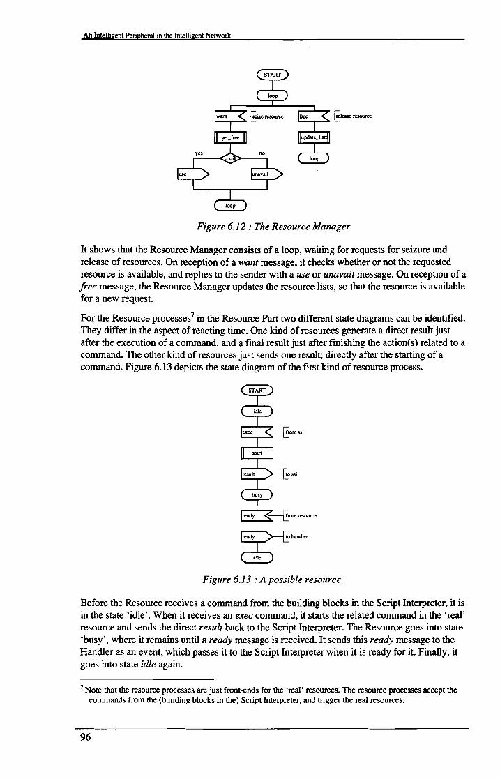
An Intelligent Peripheral in the Intelligent Network
Figure 6.12 : The Resource Manager
It shows that the Resource Manager consists of a loop, waiting for requests for seizure andrelease of resources. On reception of a want message, it checks whether or not the requestedresource is available, and replies to the sender with a use or unavail message. On reception of afree message, the Resource Manager updates the resource lists, so that the resource is availablefor a new request.
For the Resource processes7 in the Resource Part two different state diagrams can be identified.They differ in the aspect of reacting time. One kind of resources generate a direct result justafter the execution of a command, and a fmal result just after fmishing the action(s) related to acommand. The other kind of resources just sends one result; directly after the starting of acommand. Figure 6.13 depicts the state diagram of the ftrst kind of resource process.
Figure 6.13 : A possible resource.
Before the Resource receives a command from the building blocks in the Script Interpreter, it isin the state 'idle'. When it receives an exec command, it starts the related command in the 'real'resource and sends the direct result back to the Script Interpreter. The Resource goes into state'busy', where it remains until a ready message is received. It sends this ready message to theHandler as an event, which passes it to the Script Interpreter when it is ready for it. Finally, itgoes into state idle again.
7 Note that the resource processes are just front-ends for the 'real' resources. The resource processes accept thecommands from the (building blocks in the) Script Interpreter, and trigger the real resources.
96
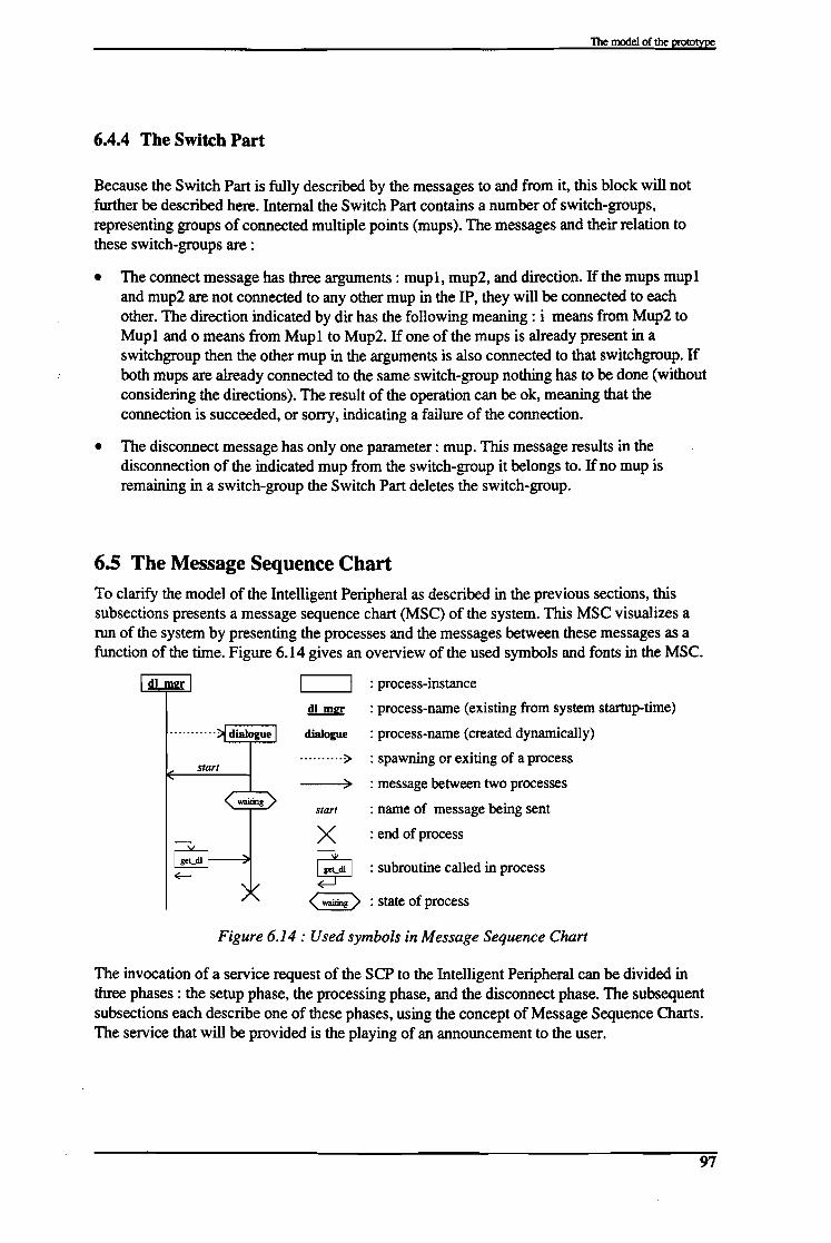
The model of the prototYpe
6.4.4 The Switch Part
Because the Switch Part is fully described by the messages to and from it, this block will notfurther be described here. Internal the Switch Part contains a number of switch-groups,representing groups of connected multiple points (mups). The messages and their relation tothese switch-groups are :
• The connect message has three arguments: mup1, mup2, and direction. If the mups mup1and mup2 are not connected to any other mup in the IP, they will be connected to eachother. The direction indicated by dir has the following meaning: i means from Mup2 toMup1 and 0 means from Mup1 to Mup2. If one of the mups is already present in aswitchgroup then the other mup in the arguments is also connected to that switchgroup. Ifboth mups are already connected to the same switch-group nothing has to be done (withoutconsidering the directions). The result of the operation can be ok, meaning that theconnection is succeeded, or sorry, indicating a failure of the connection.
• The disconnect message has only one parameter: mup. This message results in thedisconnection of the indicated mup from the switch-group it belongs to. Ifno mup isremaining in a switch-group the Switch Part deletes the switch-group.
6.5 The Message Sequence ChartTo clarify the model of the Intelligent Peripheral as described in the previous sections, thissubsections presents a message sequence chart (MSC) of the system. This MSC visualizes arun of the system by presenting the processes and the messages between these messages as afunction of the time. Figure 6.14 gives an overview of the used symbols and fonts in the MSC.
<waiting> : state of process
start
~
dialogue
.•........ ;>
)
start
x~
: process-instance
: process-name (existing from system startup-time)
: process-name (created dynamically)
: spawning or exiting of a process
: message between two processes
: name of message being sent
: end of process
: subroutine called in process
Figure 6.14: Used symbols in Message Sequence Chart
The invocation of a service request of the SCP to the Intelligent Peripheral can be divided inthree phases: the setup phase, the processing phase, and the disconnect phase. The subsequentsubsections each describe one of these phases, using the concept of Message Sequence Charts.The service that will be provided is the playing of an announcement to the user.
97

An Intelligent Peripheral in the Intelligent Network
6.5.1 The setup phase
Before the Intelligent Peripheral can execute a service for the SCP, it has to be connected to theuser (the person that uses a network service) via the SSP. Figure 6.15 depicts the setup phaseof a IP service request.
I SSF I I isdn int I I.eon mgI: I I dI mgr I I scf Int I I SCF I-' ctr
setup
seize cS/7l
...... csm Is,rm seizedseize dl ....
,...... dialogue I
......-I----,.
dialogue C~dl....starr
-,connect ariconnect ari--active (connected
--rFigure 6.15: Message Sequence Chart ofIntelligent Peripheral (setup-phase)
When the service script in the SCP needs a specialized resource for its execution, it fIrst sendsa connect_toJesource (ctr) message to the SSP, indicating the network address of theIntelligent Peripheral, and a correlation_id to identify the service process in the SCP. The SSPwill then send a setup message to the Intelligent Peripheral on the ISDN-channel connecting theSSP and the IP.
On reception of the setup message the ISDN-interface in the IP seizes a CSM by sending theConnection Manager a seize_csm message. The Connection Manager replies to this message bysending a csm_seized message, and spawns a CSM. The CSM seizes a dialogue by sending aseize_dialogue (seize_dl) message to the Dialogue Manager. The Dialogue Manager spawns adialogue process, registers the dialogue in the SCF-interface, and sends a dialogue_seized(dl_seized) back, indicating the process-id of the dialogue. Then it starts the dialogue bysending a start signal. The CSM sends a connect message to the ISDN-interface, which passesthis message to the SSP to complete the ISDN setup. Finally, the dialogue sends anassistJequest_instructions (ari) message to the SCP via the SCF-interface, to indicate that theIP is ready to execute an action for the SCPo
6.5.2 The processing phaseAfter the setup phase is fmished, the dialogue is in the ~connected' state, waiting for anoperation from the SCP. Figure 6.16 depicts one of the possible operations, theplay_announcement operation.
98

The model of the prototYpe
I,resou~ I I res mllr I I sw m...l! I Idialogue I f scf int I I SCF I
~ ;Iay ann--,.....-r
;Iay ann
I handler ......
I ssi ~~<ser_~eractio9>WllII_DlSg
want
use .....
,"",connect
ok,
set mon
.., play~
result .....,ready evt:l
anm end...
..flnm ena
Idisconnect~
free
srr .....
,v... ~J!..I!..) srr
,v...~~.. ;, srr .....
Figure 6.16 : Processing-phase ofthe play announcement operation
The SCP sends a play_announcement message to the SCF-inteIface, containing thecorrelation_id. On the basis of this correlation id, the SCF-inteIface detennines the relateddialogue process-id, and it passes the play_announcement message to the dialogue. Onreception of this message, the dialogue starts a Handler process, which will spawn a ScriptInterpreter to run the PlayAnnouncement script. The next chapter will discuss this script moredetailed, this section will just describe the actions that occur during the execution of the script.First a Resource is seized by sending the want message to the Resource Manager. This willindicate the process-id and the mup to the Script Interpreter in the use message. Then the ScriptInterpreter requests the Connection Part (sw_mgr) to connect the incoming mup (ISDN Bchannel) to the resource mup, by sending the connect message. Mer reception of the okmessage, indicating the successful connection, the Script Interpreter starts the message bysending the play message to the Resource process, and sets a monitor on the end of theannouncement (anm_end). The Script Interpreter receives the result message, indicating thesuccess or failure of the play message. Then the Script Interpreter indicates that is ready for thereception of events by sending the readyJor_events (ready_event) message to the Handler. Ifthe Handler receives the anm_end event, it sends a anm_end message to the service Interpreter,which will then disconnect and release the Resource (by means of the messages disconnect andfree). If the SCP asked for a specialized_resource_report the Script Interpreter will send thisvia the dialogue and the SCF-inteIface. Finally, the Script Interpreter and the Handler exit.
6.5.3 The disconnect phaseMer the processing phase has fmished, the disconnection between the SSP and IP can beinitiated by the IP itself or by the SCP. Figure 6.17 depicts the IP initiated disconnection.
99

An Intelligent Peripheral in the Intelligent Network
Figure 6.17 : MSC ofIntelligent Peripheral (SRF-initiated disconnection)
The Script Interpreter sends a disconnect message to the dialogue, indicating that theconnection has to be released. The Script Interpreter and the Handler will exit, and the dialoguewill send a release (reI) message to the CSM. The dialogue will also indicate to the DialogueManager that it is ready (by sending the dl stopped message) and will exit. The DialogueManager will de-register the dialogue in the SCF-interlace by sending the del_dl message. TheCSM will send a disconnect message to the SSP via the ISDN-interlace, and it will exit
Figure 6.18 depicts the SCP initiated disconnection of the Intelligent Peripheral.
I SSF I IIsdn int I I.eon mgd I csm I I dl m.Jrr I Idialogue I I sef int I I SCF I.....-l--,.
dfc( active ) <connected'-----'
disconnect..
disconnect
rei
release
~ release 141 stopped~
del dl
EXrr,/
EXIT '/fe:! ...........
f::: ........... "
Figure 6.18: MSC ofIntelligent Peripheral (SCF-initiated disconnection)
To initiate the disconnection, the SCP sends a disconnectJorwardJonnection (dfc) messageto the SSP. The SSP will send a disconnect message to the IP, which will be passed to theCSM by the ISDN-interlace. The CSM will indicate the disconnection request to the dialogueby sending the reI message, and confmn the disconnection by sending the release message tothe SSP (via the ISDN-interlace). Then it will exit. The dialogue will send a dl_stoppedmessage to the Dialogue Manager and exit, and the Dialogue Manager will de-register it in theSCF-interlace by sending the del_dl message.
6.6 ConclusionsThis chapter described the model of the prototype Intelligent Peripheral by using the formalspecification language SDL. It showed how a formal specification language can be used todescribe a system on different levels of abstraction. It defmed the interlaces to the system, bydescribing the messages and the parameters on these interlaces.
100
The model of the prototype
It showed how a complex system can be divided into smaller parts, to provide the designer witha way to abstract from details. First it defmed the prototype Intelligent Peripheral on a systemlevel, and the interfaces of the system to its environment. The next step was to divide thesystem into four functional blocks. The Access Part provides an interface to the ServiceSwitching Point in the Intelligent Network, and to the Internet. The Switch Part provides aninterface to the internal switch in the Intelligent Peripheral. The Resource Part contains andmanages the processes that control the specialized resources in the Intelligent Peripheral.Finally, the Control Part contains the core-functions of the Intelligent Peripheral, it takes careof the execution of services, and the communication to the rest of the Intelligent Networknodes.
The functional blocks described above were split up again. Several processes were identified ineach functional block, and the communication between these processes was defmed. Finally,the function of the processes was described by state diagrams and signal flows.
Finally, the prototype system was described by means of a Message Sequence Chart, showingthe processes in the system, and the messages between them as a function of the time.
101

7. The implementation of the prototyp_e _This chapter describes the implementation of the Intelligent Peripheral. This implementation is theresult of the research described in the previous sections. The fIrst subsection describes the mappingof the implementation on the model as described in the previous chapter. The second subsectiongives an overview of the system, and identifIes the several parts of the system (software andhardware). The third subsection gives an overview of the existing code in the Rapid ServicePrototyping (RSP) tool, that has been re-used in the implementation. Also it describes the changesthat had to be made in the existing code, and gives an overview of the software that had to bedeveloped. The fourth subsection describes a part of this software, the core functionality of the SRF.The next two subsections describe the building blocks and the scripts needed for the execution ofservices in the SRF. Finally, the last subsection describes the test-procedure, and the results of thesetests.
7.1 Overview of the design of the implementation.The result of the research described in the previous chapters fmally lead to an implementationof a prototype Intelligent Peripheral in the Rapid Service Prototyping tool (RSP-tool) in theIntelligent Network Applications Laboratory (INAL). Figure 7.1 again depicts the IntelligentPeripheral in relation to other functional entities in the RSP-tool.
SCEF : Service Creation Environment Function
SMF : Service Management Function
SCF : Service Control Function
SSF : Service Switching Function
NMF : Network Management Function
metco ection
SCEF NMF
ISMF
ISCF
ISSF Intelligent
Peripheral
UM-hardware UM-hardwareInte
~ ~nn
Figure 7.1 : The Intelligent Peripheral in the RSP-tool.
The interfaces between the Intelligent Peripheral and the RSP-tool are summarized below. Theywere already extensively described in chapter 5.
• The interface to the SSF is an ISDN-PRA link. This makes it possible to have thirty callsserved by the Intelligent Peripheral. The D-channel is used to setup connections and makesit possible to send text on a user-to-user based protocol.
• The interface to the SCF is implemented by the use of the distribution mechanism providedby Erlang (the language in which the RSP-tool is implemented). The messages on thisinterface are proprietary. They support most INAP features, and more.
103

An Intelligent Peripheral in the Intelligent Network
• The interface to the Internet primary serves as a gateway to E-mail. This is implemented byusing the Internet-connection of a UNIX workstation.
• The interface to the NMF is using the distribution mechanism provided by Erlang.
Figure 7.2 depicts an overview of the implementation of the Intelligent Peripheral.
r··.·-----·----··.·····.·······.·.IP:
Ethernetinterface 1
LIM
I hardware Iresourcesisdn
• interface
~ 1:::..=..=...=..=--.._.._.._.._.._.._.._.._.._.. ---l• .••
Figure 7.2 : Overview ofprototype Intelligent Peripheral
It shows two boxes, visualizing the physical boundaries of a SUN workstation and a LIMmagazine. The concepts of a LIM magazine are described in chapter 2. The SUN workstationneeds two Ethernet interfaces, one for the interfaces to the other function entities and to theInternet, and the second for the connection to the LIM. This connection carries all call-controland resource control messages to and from the LIM. The SUN workstation also needs ananalog audio input and output channel to make the SUN audio capabilities accessible for theIntelligent Peripheral. The software running in the SUN workstation consists of some UNIXapplications and an Erlang interpreter. The UNIX applications represent some of the resources.The Erlang interpreter implements the model described in the previous chapter. Table 7.1provides an overview of the various components in the SUN workstation and their functions.
Table 7.1 : Components in the SUN and their function.
Component Function
Ethernet interface 1 Interface to Internet,interface to RSP-tool functional entities SCF and NMF
Ethernet interface 2 Interface to LIM ma1:!:azineAudio input Recordin1:!: of speech from LIMAudio output Playin1:!: of speech to LIMErlang interpreter IP software: model described in chapter 6UNIX software: play Resource to play audio-fileUNIX software: rsynth Resource to synthesize text.UNIX software: sendmail Resource to send an E-mail to Internet.
104

The implementation of the prototype
The UM magazine also needs an Ethernet interlace for the connection to the SUN workstation.It also has two analog lines (one input and one output), to connect to the SUN workstationaudio lines, and an ISDN-PRA interlace, for the connection to the SSF in the RSP tool. Theother hardware in the LIM magazine implements the resources. Table 7.2 provides anoverview of the various components in the UM and their functions.
Table 7.2 : Components in the UM and their function.
Component FunctionEthernet interlace Interlace to SUN workstationELU AnalOg lines (input and output) for speech-connection to SUNTLU76 Interlace to RSP-tool functional entity SSFVSU Resource to play and record speechTMU Resource to play and receive (dtmf) tonesSwitch Internal switch to connect users to resources
Figure 7.3 depicts these components in relation to each other.
--~-g-------'- -
IiISUN
- interface I I network CP 1I serverIiI
III AP SP RP
iII 'I······ . p- ...._.-. ....... -.I
I
IIErlam!
lim-driver
! Unix I
1IE-mail I .••J??Y. .. ~Ii server I driver software iL I
Ethernet I ffi~interface 2 m out
Ethernet link L JAudio links
Ethernet UM
I r--i interface ~link isdn speech tone & analog
interface card switch multiparty line
I I Ibackplane
ISDN-PRA
Figure 7.3 : More detailed picture of implementation.
This picture again depicts the UM magazine and the SUN workstation. The Erlang code, beinginterpreted in the workstation, implements the model described in the previous section. Outsidethe model, the lim_driver acts as an interlace towards the low-level signaling on the Ethernetconnection to the LIM. The lim_driver communicates with the EPU-driver, a process thathandles the low-level Ethernet communication. Processes in Erlang can subscribe to messages
105

An Intelligent Peripheral in the Intelligent Network
coming from specific mups in the LIM. The lim_driver will take care of the distribution of themessages from the LIM.
Several parts of Erlang code for the Intelligent Peripheral, especially the low-level parts, havethe same functional needs as the parts in the SSF node in the RSP-tool. These parts will be reused wherever possible. The next subsection describes how this re-use of code can be achieved,without compromising to the model described in the previous chapter.
7.2 The implementation off the model.
Figure 7.4 depicts an overview of the model described in the previous chapter.
.................................................... .ControlPan
. ..... - .
. . ........... ..
D Newcode
D Partly new code
D Existing code
Figure 7.4 : Overview o/the model o/the prototype Intelligent Peripheral.
Table 7.3 shows the processes, and describes whether the implementation can be re-used. Thefollowing subsections describe the implementation more detailed.
106

The implementation of the prototYpe
Table 7.3 : Processes and their implementation.
Process ImplementationISDN-interface isdn netw ncrConnection Manager isdn origcall: loopOConnection State Machine simplified/changed isdn origcall statesMail Server newDialolnle Mana2er newcr dialogue newncr dialo2\le newSCF-interface newHandler chan2ed handler10Script Interpreter fspilOResource Mana2er newResource new/re-use of existin2Switch Part connection management + existing code
7.2.1 The Access Part
The ISDN-interface is a process that takes care of the handling of the ISDN-protocol stack.The PRA (Primary Rate Access) network side has already been developed for the connection ofa DECf (Digital Enhanced Cordless Telephony) Radio Exchange. The PRA user side can bederived from the network side with some little adaptions. The changes to the software are listedbelow.
• Added function start(Address,Side) in tlu76.erl, to make it possible to start the isdn-accessas user-side or network side from the facts-fJle (facts.erI).
• Change of isdn_access.erI to isdn_usecaccess.erI to indicate to start the hardware as userside in stead of network-side.
• Change of isdn_interface.erI to isdn_user_interface.erI to remove clock-management foruser-side.
The Connection Manager is integrated with the Connection State Machine in one erIangmodule; isdn_origcall.erl. The Connection Manager is implemented as the function loop in themodule, and the Connection State Machine is implemented by a set of functions-ealls. Thename of the module is isdn_origcall, to make integration of the old software possible.
The Mail Server is implemented by a client-server system. The server is a process with aregistered name 'mail_server'. It just waits for messages from clients. The clients are started bythe UNIX mail-system. When mail arrives the UNIX system checks the .maildelivery fJle todecide what action should be taken. If the E-mail is directed to the Intelligent Peripheral, the.maildelivery file causes an Erlang shell to be started, and sends the mail-contents to theprogram running in the shell. The program parses the E-mail. It extracts the addressee, thesender, the subject, and the contents of the E-mail, and sends these to the server. The serverwill then start a dialogue in the Control Part of the Intelligent Peripheral. There the E-mail willbe further processed.
107

exec
An Intelligent Peripheral in the Intelligent Network
7.2.2 The Switch Part
For the Switch Part in the Intelligent Peripheral, many modules can be re-used from the SSFpart of the RSP-tool. In the SSF, call-related processes are responsible for the control of theswitch. This way of switch control is not applicable to the Intelligent Peripheral. The control ofthe switch in the Intelligent Peripheral must be call-unrelated, because it must be possible toconnect the resources to the user dynamically, and it must be possible to connect two resourcesto each other, without any relation to al call. The module cma.erl (connection managementarchitecture), developed in another INAL-project, can be used to achieve the desired control tothe switch. The interface provided by this module is described in section 6.3.
7.2.3 The Resource Part
The resources in the Resource Part must have a generic interface to the building blocks in theControl Part. This interface is described in section 6.3. Therefore, for every resource a separateprocess must be present, controlling the resource. The following paragraphs describe thisprocesses for each resource.
For the playing of speech messages from the VSU hardware board, the module vsu.erl providesan interface to the hardware. Figure 7.5 depicts the messages on this interface, relevant to theplaying of a message, together with the speech_player process, which provides the interface tothe building blocks in the Control Part.
result.ok
speech-player -....3IC.,---,.,.-J----------,.,-J-
vsu_disconnection_ok
vsu_action_okvsu loop ----:...--=..3IL-l_=----....:=-- ----l._
Figure 7.5 : Interface to speechylayer.
For this resource, the speech_player process only needs to translate the names of the messagesto the generic names.
For the recording of speech messages to the VSU hardware board, the vsu-module alsoprovides an interface to the hardware. Figure 7.6 depicts the messages on the interface, andshows the speech_recorder process, needed to provide the interface to the building blocks.
eX~::Ult.vsu_action_nok
vsu_aetion_ok stop_action vsu_action_okvsu loop _----"'--'- .L..-_
Figure 7.6 : Interface to speech recorder.
Just like the speech_player, the speech_recorder process just translates the messages to thegeneric names. The end of the recording can be initiated by the hardware (i.e. when the speechmemory is full) and by the building block (i.e. when a maximum message-length is specified, orwhen the service in the scp detected that the user is gone on-hook). The building block shouldthen send the stop command in the exec-message.
The synthesizing of speech is executed by a public domain package called rsynth (version 2.0 isused in the prototype). This is a C-coded package, and it can be compiled for several operatingsystems. It supports the use of customizable databases, which improve the pronunciation of the
108

The implementation of the prototype
synthesizer. The resulting executable, say, reads text from standard-input, and sends thegenerated output to the UNIX audio device. The result of say is an empty string. If an erroroccurs the shell will send an error-message to standard error. Figure 7.7 depicts the processesneeded to provide the generic interface towards the building blocks.
result. result,exec ok ready exec nok ready
speech_synthesizer speech_synthesizer
exit exit
timertime_out
playet"''-T--------..-J
unix:cmd []
a. normal situation b. error situation
Figure 7.7 : The speech_synthesizer.
Because the UNIX call to the say executable does not generate a direct result ifno erroroccurs, the timer process is started. If the timer value is reached before a result is received fromthe shell, it is assumed that the synthesizer is busy, and that the result of the command is ok. Ifthe UNIX shell generates a result before the timer value is reached, the speech_recorderprocess passed the result to the building block.
The playing of (UNIX) audio-flIes to the user is achieved by the use of the UNIX playcommand. This command has the same properties as the synthesizer described above, so theaudio_player process is identical to the speech_synthesizer process.
The sending of mail is achieved by the use of the UNIX sendmail command. This commandreads its input from stdin, and sends this input to the address that it gets by the commandparameter receiver, which has to be an existing E-mail address. If the E-mail address does notexist, the message will be returned. If the action succeeds, the UNIX shell returns an emptystring, otherwise it returns an error message via standard error. Figure 7.8 depicts themail_sender process. It simply translates the messages to the generic names.
3tsult•exec ok
mail sender
unix:cmd [result]
Figure 7.8: The mail_sender.
The sending of dtmf-tones (dual-tone multi-frequency) to the user is achieved by the TMUhardware board. A process code_sender is controlling the code sender resources at this board.Figure 7.9 depicts this process, together with the dtmCsender process, which provides thegeneric interface to the building blocks.
result.ok
ok
exec
send_numbe
code_sender -----"'-""----
dtmCsender --""'-T~lIt'""-
Figure 7.9 : The dtmf-sender.
109

result.ok
An Intelligent Peripheral in the Intelligent Network
The receiving of dtmf-tones from the user is also achieved by the TMU-hardware board. Aprocess codeJeceiver is controlling the code receiver resources at this board. Figure 7.10depicts the dtmf_receiver process, together with the code_receiver process, and the messagesbetween them.
execdtmCreceiver-~..L--....".......---- ........--
staIt_rece veing
Figure 7.10 : The dtmLreceiver.
The dtmf_receiver process not only translates the messages to the generic names, but also takescare of time-out values indicated by the building block. It also takes care of the handling ofstart-of-input digits, end-of-input digits. The ready message contains the reason why the inputis ready, i.e. maximum number of digits received, end-of-input digit received, or time-outoccurred.
Finally, the sending of tones (dial, busy, congestion, fault) to the user is also achieved by theTMU-hardware board. At the startup of the Intelligent Peripheral, for each type of tone a tonesender is started. Because the tone-senders can send a tone to many incoming channels, this ismore efficient than starting a tone-sender for each request. So, if a building block needs to senda tone to a user, it just has to connect the user to the correct multiple point. Because the tonesenders are always sending the tones, no process is needed to control them.
Every resource process, except the mail_sender and the tone_sender can also be stopped by thebuilding blocks, by the sending of a stop message. An extra timer can be started to avoidresources causing the system to go in a dead-lock situation.
The Resource Manager is implemented as a loop-function in the resource_manager module.After startup it constantly waits for resources to register them, and for building blocks, seizingand releasing resources. It keeps track of the available and occupied resources by putting allresources in a list.
7.2.4 The Control PartThe processes in the Control Part take care of the execution of the services, and co-ordinate theactions of the Intelligent Peripheral. The modules have been designed such, that the ScriptInterpreter and Handler processes could been re-used from the SCF part of the RSP-tool. Oneof the advantages of this approach is the possibility to use the existing Service CreationEnvironment to create services, and to use the Network Management Function to trace scriptsin the Intelligent Peripheral. Also, to re-develop these parts is a big job, and a waste of time.
The dialogue_manager module is the implementation of the process Dialogue Manager in theSOL-model. It is a simple loop, waiting for messages and spawning. If a dialogue crashes, thedialogue manager will detect this, and it will release the resources.
The modules ccdialogue and nccdialogue implement the call-related and non-call-relateddialogues. The modules implement the state-models by a set of functions, corresponding to thestates in the SOL-model.
110

The implementation Of the prototYpe
The module srf45 implements the functionality needed for the communication of the IntelligentPeripheral to the SCPo It uses the correlation_id to correlate the ISDN connection to the userwith the dialogue to the SCP. Also it provides some translation of messages to integrate theIntelligent Peripheral in the existing RSP-tool, and to make re-use of existing code possible.
The handlerI0 module can be re-used from the SCF part of the RSP-tool. Some modificationshave been introduced, because the 'SCF handler' exits if no jobs have to be done and no callrelated events are outstanding. To avoid this, a new SSF-state, 'no ssf is introduced in thehandlerl0 module.
The fspilO code can be re-used without modifications from the SCF-part of the RSP-tool, andcorresponds to the Script Interpreter process in the SDL-model.
7.2.5 Other softwareThe modules described above, provide the functionality of the Intelligent Peripheral asdescribed in section 3. To use the Intelligent Peripheral in the RSP-tool, it needs an interface tothe NMF of the RSP tool. The module responsible for this is the start module. This modulecreates a node, starts the hardware and all processes needed in the Intelligent Peripheral, suchas the Resource Manager, the Dialogue Manager, and all the Resource processes.
Also, a stop function is present, which is needed to take the Intelligent Peripheral out of action.
The following subsections describe the scripts and building blocks, that can (and must) be usedto let the Intelligent Peripheral cany out any actions.
7.3 Scripts and building blocks in the SCP and IPSection 2.2.1 already described the concepts of scripts in the Intelligent Network concept. For adescription of scripts and building blocks in the RSP-tool, check the SIB DESIGNERS GUIDEFOR THE RSP [Velden].
This subsection describes an example of scripts and building blocks in the SCP and in the IP.The next subsection describes the building blocks which can be used to build scripts.
This example describes the 'tell-time' service, and it serves to make the use of scripts andbuilding blocks in the SCP and IP clear. When a user calls a special number the 'tell-time'service will send an announcement to the user which tells the correct time.
111

An Intelligent Peripheral in the Intelligent Network
Figure 7.11 shows the scf-script for this service.
start get-time connect IP playannouncement
disconnect IP
Figure 7.11 : The SCP Tell-Time script.
After the script has started by the start10 building block, the gtI 0 building block gets thesystem time, and generates the text that has to be pronounced by the speech-synthesizer. ThectrlO building block requests the SSF to connect the user to the Intelligent Peripheral. Whenthe IP sends an assiscrequescinstructions message, the script invokes the palO building block,which sends a play_announcement message to the IP. After the playing of the text has fmished,the palO building block receives a specialized_resource_report, and fmally the dfc buildingblock requests the SSF to disconnect the Intelligent Peripheral.
Figure 7.12 depicts the script that runs in the IP as a result of the play_announcementmessage.
Figure 7.12 : The IP PLAY script.
The IP just starts the pa40 building block, and dependent on the outlet of that block, sends theresult (ok or nok) to the SCP. If the result is ok then the done40 building block causes thescript-interpreter to go in a 'waiting' state. It remain in this state untill the resource reports theending of the announcement. Then the pa40 building block selects the 'complete' outlet, and thesendsrr building block sends a specializedJesourceJeport message to the SCPo Finally, thedisc40 building block checks if the SCP ordered the disconnection to the SSF (this is indicatedin one of the data-fields of the play_announcement message), and in the quit40 building blockthe script ends.
Figure 7.13 clarifies the distributed execution of the service by means of a timing diagram.
112

The implementation of the prototYpe
I user I I SSP I I SCP I I IP I lresoun:e~
call :06-40,
initial dp ~ TELL TIME
I ~ ARTIO
I GTIO
- errCTRIO
setup ..... .,
I ~NEIO
Iari
CTRIO
PAlOplay anm .....
PLAY
SlrART401want
PA40use
connect ~
- ok
play
ok
ok
user-interaction ULT I-- -------------- ------- ------ ----- - ------ ----- -------- _.
I ~NEIO lONE40 I
PA40ready
I PAlO srr SEN [)SRR40 I- dfc
Dlsc401DFCIO
I QUITIO QUJT40
disconnect ~
rei,
Figure 7.13 : Messages during execution ofTell-Time script.
This picture depicts the messages between the Intelligent Network nodes SCP, SSP, IP, theuser, and the resources in the IP. First, when the user calls the special number 0640, the SSPrequests the SCP to start the script 0640, described above. The CfRlO building block sends aconnect_toJesource (ctr) message to the SSP, and the SSP sets up a connection to the IP viathe ISDN link (setup). The IP sends an assist request instructions (ari) message to the SCPo- -Note that the CTR building block in the SCP is re-entrant, so when it receives theassistJequest_instructions message it selects the ari outlet (see Figure 7.11), and the SCPstarts executing the PAlO building block. It sends a play_announcement (play_anm) messageto the IP, which starts the PLAY script in the IP script interpreter. After the START40 buildingblock, the PA40 building block requests a resource, connects the resource to the incoming side,starts the playing of the announcement, and selects the ok outlet. The SENDRESULT buildingblock sends the ok message to the SCP, which is received by the PAW building block. The SCPnow waits for a specializedJesourceJeport (srr) message, which will be sent by theSENDSRR building block in the IP PLAY script. Finally, the dfclO message sends adisconnectJorward_connection (dfc) to the SSP, and the connection to the IP will be released(rel).
113

An Intelligent Peripheral in the Intelligent Network
7.4 The building blocks.
The example in the previous subsection described the tell-time script in the SCP and the Playscript in the IP. The building blocks appeared as atomic parts. This section will zoom in on theinternals of both the IP-related building blocks in the SCP and the building blocks in the IP.The building blocks are implemented as Erlang modules. The code of these Erlang modules isnot listed here (the code of one of the building blocks is listed in Annex A). A description of thedevelopment of building blocks can be found in [Velden]. The figures in this section use thelayout of Figure 7.14 to depict the building blocks.
service support data
outlets
call instance data result data
Figure 7.14 : Graphical representation ofbuilding blocks.
The function-name of the building block is placed inside the box, representing the buildingblock.
The initial call of the building block is represented by the straight arrow on the left side of theblock. If a building block is re-entrant, than the "flashed" arrow on the left side represents thisre-entrancy. The name besides the arrow indicates the event that causes the re-entry of thebuilding block. The outlets are represented by arrows on the right of the building block. Thearrow on top of the building block represents the service-support data, i.e. the data that has tobe defmed by the service designer. The arrow below the building block on the left representsthe call instance data, the data that can be different for each invocation of the service (i.e. thecalling number). Finally, the arrow below the building block on the right represents the resultdata. This is the data that is produced by the execution of the building block, and that can beused by the other building blocks in the service script.
7.4.1 The SCF building blocks
This subsection describes the SCP-building blocks that are related to the operation of theprototype Intelligent Peripheral.
The ConnectToResource building block
Figure 7.15 depicts the ConnectToResource (CTRlO) building block.
okCTRIO nok
ari
Figure 7.15 : The Connect To Resource building block.
114

The implementation of the prototYpe
The CfRlO building block takes the srf_address as a selVice parameter. The building blockgenerates a unique correlation_id. This correlation_id enables the IP to correlate the ISDNsetup message from the SSP to the dialogue between the IP and the SCPo Then it sends aload_data operation to the SSP, containing the data needed to connect the IP to the user. Thisload_data message is referred to as connecCto_resource. Then the building block selects the'ok' or 'nok' outlet, dependent on the result of the load_data message to the SSP. The ari entryactivates when the SCP receives an assiscrequescinstructions message from the IP. Thebuilding block will store the IP-node in its process-data, so that the script interpreter knowswhere to send subsequent messages. Finally, the building block selects the ari outlet.
The DisconnectForward Connection building block
Figure 7.16 depicts the Disconnect Forward Connection (DFCIO) building block.
---1 DFCIO ~~nok
Figure 7.16: The Disconnect Forward Connection building block.
The DFCIO building block just sends a load_data message to the SSP, to disconnect the IPfrom the user. This load_data message is referred to as the disconnectJorward_connectionmessage. Depending on the result of the load_data, the building block selects the 'ok' or 'nok'outlet.
The PlayAnnouncement building block
Figure 7.17 depicts the Play Announcement (PAlO) building block.
infonnation_to_send,disconnection_forbidden,requesCsIT
okPAlO nok
SIT
Figure 7.17 : The Play Announcement building block.
The PAlO building block orders the IP to play an announcement to the user. The selVicedesigner has to provide the building block with the following parameter values:
• information_to_send to indicate the type and the contents of the message to the user.
• disconnectionjorbidden to indicate whether the IP is allowed to release the connectionafter the announcement has fmished.
• requescsrr to indicate whether the SCP wants to be informed about the end of theannouncement.
First, the PAlO building block sends a play_announcement message to the IP. Dependent onthe result of that message, it selects the 'ok' or 'nok' outlet. If the value of the requescsrr
115

An Intelligent Peripheral in the Intelligent Network
parameter is yes_SIT, the PAlO building block will be re-entered after the IP sent aspecialize<Cresource_report message to the SCP. Then the building block will then select the'SIT' outlet.
The PromptAndCollect building block
Figure 7.18 depicts the Prompt And Collect (PNClO) building block.
infonnation_to_send,infonnation_to_collect,disconnection_forbidden,where_to_pucresult
okPNCIO nok
result
Figure 7.18 : The Prompt And Collect building block.
The PNCI 0 building block orders the IP to play an announcement to the user, and to collectinformation from the user. This collected information can be of several types. The servicedesigner has to provide the building block with the following parameter values:
• information_to_send to indicate the type and the contents of the message to the user.
• information_t030llect to indicate the type of the information to collect from the user.
• disconnectionjorbidden to indicate whether the IP is allowed to release the connectionafter the collecting of information has fmished.
• where_to_puccollected_info to indicate what should happen to the collected information.
First, the PNCIO building block sends aprompt_and_collect message to the IP. Dependent onthe result of that message, it selects the 'ok' or 'nok' outlet. The PNCIO building block will bere-entered after the IP sent a collected info message to the SCPo The building block will storethe collected information in the place indicated in the where_to_pucresult datafield, and it willselect the 'result' outlet.
The RunScript building block
Figure 7.19 depicts the Run Script (RS I0) building block.
116

The implementation of the prototype
scripUd.scripCdata,where_to_pucresult
okookcomplete
Figure 7.19 : The RunScript building block.
For the RSIO building block the service designer should specify the following parameters:
• scripCid indicates the name of the script that the SCP wants the IP to execute.
• scripCdata optionally provides the IP with data needed for the execution of the scriptindicated above.
• where_to_pucresult indicates where the building block should store the data that resultsfrom the execution of the script in the IP.
The RS 10 building block sends a run_script message to the Intelligent Peripheral, containingthe scripCid and optionally the scripcdata. If it receives an ok message from the IP it selectsthe 'ok' outlet. If the IP indicates that it does not know the script, by sending a load_scriptmessage, the RS 10 building block will fetch the script logic from the SCP data-base, and it willdownload it to the IP. The IP will send an ok message if the downloaded script starts running.The RSIO building block then selects the 'ok' outlet. When the SCP receives a runJesultmessage from the IP, the RS 10 building block is re-entered, it will store the result data in theplace indicated in the where_to_pucresult data field, and it will select the 'complete' outlet.
The next subsection describes the counterparts of the described SCF building blocks, the IPbuilding blocks, and the scripts in which they are running.
7.4.2 The IP building blocks and scripts
Section 7.3 already introduced one important IP script and building block, the PLAY script andthe PA40 building block (PA, PlayAnnouncement). This subsection describes this PLAY scriptand PA40 building block, and the other IP scripts and building blocks needed for the operationof the Intelligent Peripheral, more detailed. To clarify the implementation of the buildingblocks, the Erlang code of one building block (PA40) is included in annex A.
The PLAY script and its building blocks
When the Service Control Point wants the Intelligent Peripheral to play an announcement, itsends a play_announcement message. The reception of this message causes the IP to start thePLAY script. Figure 7.20 depicts this PLAY script.
117

An Intelligent Peripheral in the Intelligent Network
Figure 7.20: The srfPLAY script.
After the script has started, the PA40 building block will identify which kind of announcementhas to be played. It seizes the required resources, and connects them to the incoming line (theISDN B-ehannel). Then it will start the playing of the announcement. The PA40 building blockwill be described in detail below. Depending on the result of the actions, the PA40 buildingblock selects its 'ok'or 'nok' (not ok) outlet, and the SENDRESULT building block sends thisresult to the Service Control Point. If the result is not ok, the script will terminate, but normally(result is ok) the DONE40 building block causes the script interpreter to wait for an event (theready event, indicating the end of the announcement) from the resource. If this event isreceived, the PA40 building block selects its 'complete' outlet, and the SENDSRR building blockwill send a specializedJesourceJeport message to the SCP (if requested by the PAW buildingblock in the SCP). Then the DIsc40 building block will release the connection to the SSP(again, if requested by the PAW building block in the SCP).
The building blocks of the PLAY script
On the outside, the IP building blocks resemble the SCP building blocks. Internally, thebuilding blocks are very different, however. Whilst the SCP building blocks communicate tothe Intelligent Peripheral, the IP building blocks communicate to the hardware in the IntelligentPeripheral itself. The IP building blocks have to take care of the execution of the requestedservices. All building blocks are designed to execute one or more atomic operations. Theseoperations are mostly of the form: action followed by result.
Figure 7.21 is a part of Figure 7.13. This picture shows the messages to and from the PA40building block as in the example of section 7.3.
nect
pa40 selects complete outlet
pa40 selects ok outlet
PA40want,
use,
connect
ok.....
play
ok,
,•• ••• a ..........
PA40 ~free,
disCOQl
" ...............
Figure 7.21 : Function ofPlayAnnouncement building block.
118

The implementation of the prototYpe
When the building block is being started by the script interpreter, first it detennines whichresource is needed for the execution of the seIVice. Then it requests this resource to theresource-manager in the IP. If the resource is available the resource manager will reply to thisrequest with the resource's multiple point in the LIM and the process-id, to which the buildingblock should send the play command. Then the building block sends a connect request to theSwitch Part, to create a speech connection between the resource and the incoming side. Afterthe connection has been successfully established, the building block sends the play command tothe resource's process-id, receives a (direct) result from the resource, and selects the 'ok'outlet. The building block sets a monitor on the ready message from the resource. When thismessage is received by the script interpreter, the PA40 building block will be entered in thenccevent mode. It will release the resource by sending the free message to theresource_manager, and disconnect the resource from the user. Then it selects the 'complete'outlet
Figure 7.22 shows the PA40 building block.
oknokcomplete
multiple_point
Figure 7.22 : The PlayAnnouncement building block.
The building block has three outlets :
The 'ok' outlet is selected directly after the successful starting of an announcement.
The 'nok' outlet is selected directly after the failing of the starting of an announcement.
The 'complete' outlet, selected when the playing of the announcement is ended.
The infonnation_to_send data field on top of the building block determines the type andcontents of the message to send. The multiple point detennines the incoming channel to whichthe announcement should be played. Next to the use in the PLAY script, the PA40 buildingblock can be used in srf scripts that can be executed by using the RS 10 building block in theSeIVice Control Point seIVice script. The building block is also used in the SRF PLAY script, asdescribed in section 7.3.
Annex A shows the Erlang code of the PA40 building block.
Next to the PA40 building block, the PLAY script uses the SENDRESULT, SENDSRR, and DIsc40building block. These building blocks are very simple building blocks and are described below.
The SENDRESULT building block just sends a result message to the SCP. The script designerhas to indicate the contents of the result message. In the case of the play script this will be okor nok. The building block has just one outlet, 'ok'.
The SENDSRR building block has one data-field, where the seIVice designer has to indicatewether the IP has to send a specializedJesourceJeport message to the SCP. Then it selectsits 'ok' outlet.
119

An Intelligent Peripheral in the Intelligent Network
The DIsc40 building block has one data-field, where the service designer has to indicate wetherthe IP is alowed to initiate the release of the connection towards the SSP. Then it selects its okoutlet.
The PROMPT script and its building blocks
When the Service Control Point wants the Intelligent Peripheral to collect info from the user, itsends a prompt_and_collect message. The reception of this message causes the IP to start thePROMPT script, depicted in Figure 7.23.
Figure 7.23 : The srfPROMPT script.
After the script has started, the PNc40 building block will identify which kind of announcementhas to be played to the user, and which kind of info has to be received from the user. It seizesthe required resources, and connects them to the incoming line (the ISDN B-channel). Then itwill start the playing of the announcement. The PNc40 building block will be described in detailbelow. Depending on the result of the actions, the PNC40 building block selects its 'ok'or 'nok'(not ok) outlet, and the SENDRESULT building block sends this result to the Service ControlPoint. If the result is not ok, the script will terminate, but normally (result is ok) the DONE40building block causes the script interpreter to wait for an event (the ready event, indicating theend of the collecting of the information) from the resource. If this event is received, the PNc40building block selects its 'complete' outlet, and the SENDRESULT building block will send acollected_info message to the SCP, including the results of the collecting of information. Thenthe disc40 building block will release the connection to the SSP (if requested by the PNCIObuilding block in the SCP).
The building blocks of the PROMPT script
Figure 7.24 depicts the Prompt And Collect (PNC40) building block.
infonnation_to_send,infonnation_to_collect
oknokcomplete
Figure 7.24 : The Prompt And Collect building block.
Just like the PA40 building block, the PNc40 building block takes care of the seizure and releaseof resources, the connection and disconnection of the resources to the incoming channel, andthe execution of actions in the resources, needed for the execution of the requested actions. Theinformation_to_send data-field of the building block determines the type and contents of the
120

The implementation of the prototype
message to send to the user. The multiple_point determines the incoming channel to which theannouncements should be played, and from which the information should be collected. Thethree outlets of the PNc40 building block are :
• The 'ok' outlet is selected after the playing of an announcement or the collecting ofinformation is started.
• The 'nok' outlet is selected when the requested actions can not be performed correctly.
• The 'complete' outlet is selected after the bb is re-entered by a result from the collectingresources.
The PNc40 building block can be used in combination with the PA40 building block to createsrf scripts, that can be started by using the RSlO building block in the SCPo
The RUNSCRlPT script and its building blocks
The RUNSCRIPT script, depicted in Figure 7.25, is started in the Intelligent Peripheral when arun_script operation is received from the Service Control Point.
Figure 7.25 : The srfRUNSCRIPT script.
First it starts the Rs40 building block, to load the script to run from the SCP ifnecessary. If thescript is present in the srf the sendresult building block sends a result operation to the SCPoThen it uses the existing gosub building block to run the script as a subroutine (sub-script).After the sub-script has fmished, the sendrunres building block sends the result of the subscript to the SCP by the runJesult operation. Then the disconnect40 building block determineswhether the srf should release the connection to the SSF, and the script quits.
The building blocks of the RUNSCRIPT script
Figure 7.26 depicts the Run Script (Rs40) building block. In contrast to the PA40 and PNc40building blocks, this building block can not be used in IP-scripts. It only serves as thecounterpart for the RSlO building block in the SCPo
scripUd,scripCdata,
okRS40
nok
multiple_point
Figure 7.26 : The Run Script building block.
The two data fields, scripcid and scripCdata, are always substituted by the values indicated inthe run_script message, sent to the IP by the SCPo The Rs40 building block checks whether the
121

An Intelligent Peripheral in the Intelligent Network
requested script logic is present in the IP. If not, it sends a load_script message to the SCP,which will reply with the downloading of the script. The Rs40 building block will save thescript in the SRF database, and selects the 'ok' outlet. If the script was allready present in theSRF, the Rs40 building block directly selects the 'ok' outlet. After the script is executed, theRs40 building block will select the ok or nok outlet, dependent on the result of the execution.
The RUNSCF40 building block
The last building block described in this section is the RUNSCF40 building block. Figure 7.27depicts this building block.
scripUd,scripCdata,
okRUNSCF40
nok
Figure 7.27 : the RUNSCF40 building block.
The RUNSCF40 building block sends a run_scLscript operation to the SCPo On reception ofthat operation, the SCP will start the execution of a script. The building block has two servicesupport data fields. These determine the scripUd of the script to run in the SCP, and thescripCdata that the SCP has to use in the script. After the sending of the run_scLscript thebuilding block selects the ok outlet.
This subsection concludes the description of the implementation of the IP. The next subsectiondescribes a test-proposal, that describes the test procedures to cover the functionality providedby the prototype IP.
7.5 Testing of the implementation of the IP.The last phase in the development process of the prototype Intelligent Peripheral is the testphase. The implementation has to be examined against the requirements stated in section 3. Totest the main functionality of the IP, section 3.2.1 presented a benchmark service, the P-mailservice. Because of time-restrictions, not all functionality for this service has beenimplemented.
This section describes the service scripts, used to test the implemented capabilities.
The playing of announcements is tested by the script depicted in Figure 7.28.
Figure 7.28: The play-announcement test script.
122

The implementation of the prototYpe
This script is used for the testing of three types of announcements. The information_to_senddata-field of the palO building block determined these three announcements. The types arelisted below.
• Playing of a recorded message in the VSU hardware board in the Intelligent Peripheral.
• Playing of an audio-me stored on the UNIX workstation in the Intelligent Peripheral.
• Synthesizing of a text string, sent to the Intelligent Peripheral by the SCPo
Although a complete implementation of the P-mail seIVice was impossible, most of itsfunctionality is tested by the scripts depicted in Figure 7.29.
I START H RUNSCF H QUIT
start createA
a. The SRF handle-,nail script
IPUTIO H CREAlEH OONE Istart createA
b. The SCP mail_script
c. The SCP mailA script
ISTARTIOH MESG H OONElO Istart
d. The SCP identity script
e. The SCP mailB script
Figure 7.29 : The P-mail scripts.
Figure 7.29 a depicts the script in the SRF, that gets the data from the mail-seIVer (via thedialogue). This script links the receiver in the mail to a subscriber of the P-mail seIVice. Then itstarts the mail script in the SCP, and hands all mail-data to that script in the SCPo
Figure 7.29 b depicts this SCP mail script. It saves the received data from the IP in thedatabase and the CREATE building block (createA) creates a new call in the SSP, to make thetelephone of the subscriber ring, and then quits.
The creation of the call to the subscriber by the mail script causes the mailA script to start.Figure 7.29 depicts this mailA script. After the script has started, a monitor is set on the
123

An Intelligent Peripheral in the Intelligent Network
answering of the call by the subscriber. If the subscriber answers the call, the CREA1E buildingblock creates a new call in the SSP for the connection to the Intelligent Peripheral. The monitorbuilding block monitors the P-mail subscriber to disconnect.
At the same time, the answering of; the call by the subscriber, will start the identity script,depicted in Figure 7.29 d. This script will put the sender and the subject of the E-mail on thedisplay of the telephone.
The creation of the call by the mailA script (createB) causes the mailB script to start. Figure7.29 depicts this script. This script takes care of the synthesizing of the contents of the E-mail.The erR10 building block sets up the connection between the SSP and the IntelligentPeripheral, and the IPCMON building block sets a monitor on the disconnection of thesubscriber. When the script receives an assiscrequescinstructions operation from theIntelligent Peripheral it will request the IP to start the synthesizing of the text. When theannouncement is ready, it will wait for the subscriber to disconnect before releasing theconnection to the IP with the DFClO building block, and the service will quit. On thedisonnection of the subscriber the mailA script will also quit.
The prompt and collect capabilities can not be tested, because the PNC40 building block is notyet completed at the moment of writing of this report. However, the resources used by thebuilding block are tested, by sending operations to them via the Erlang shell.
For the same reason, the distributed running of a script in the Intelligent Peripheral also can notbe tested.
7.6 Conclusions.This section described the implementation of the prototype Intelligent Peripheral. It showedhow the research described in the previous sections resulted in a proposal for theimplementation of the prototype.
It described how the implementation covers the requirements, as they were defmed in section 3of the report. Every capability of the prototype was mapped on a physical resource, and anarchitecture was defmed to fit these resources together into a complete system.
It also described the integration of the SDL model (described in section 6) into theimplementation. The computer-language Erlang was used to implement the model, therebytrying to make optimal use of the software modules that were developed in the RSP-tool projectbefore. For every process in the model, a description is provided in this section. For some of theprocesses this means a short description of already existing code, and for others it is adescription of the modifications that were made on existing code. Especially for the processescontrolling the resources in the prototype, a complete description of the new developedprocesses is provided.
An important subsection is the description of the use of building blocks and scripts. Thebuilding blocks are the basic parts to build user-interaction scripts.Jn the Intelligent Peripheralthree building blocks are designed, that take care of the execution of the requested actions. Toenable the SCP to invoke the services in the Intelligent Peripheral, five SCP building blockswere designed, and they are also described in this section.
Due to time restrictions, it was not possible to implement all capabilities as stated in therequirements in section 3. Table 7.4 gives an overview of the requirements, and theimplemented capabilities of the prototype Intelligent Peripheral.
124

The implementation of the prototype
Table 7.4 : Requirements and their implementation in the prototype.
Capability Implementation statusplaying of speech implemented and tested okrecording of speech implemented, not testedsynthesizing of text implemented and tested oksending and receiving of text not implementedaccess to internet implemented and tested okstoring fIles not implementedreceiving and sending tones implemented, not testedplaying of audio-fIles implemented and tested okexecuting scripts in the Intelligent Peripheral implemented, tested okstarting scripts in Service Control Point implemented and tested oksending alarms / holding statistics not implementedupdating subscriber list not implementedinstalling service scripts implemented and tested okexecute operations pa, pnc, and rs 8 pa implemented and tested ok
pnc implemented, not tested completelyrs not implemented
handle 4 calls simultaneously implemented, not testeddynamically connect resources implemented, tested ok
8 pa = play_announcement, pnc = prompcand_collect, rs = run_script
125

An Intelligent Peripheral in the Intelligent Network
126
8. ConclusionsThis final chapter of this report summarises the results of the research described in the earlierchapters. It describes the conclusions of the research to the most important items about theIntelligent Peripheral. Where needed, it refers the reader to the appropriate sections in the report.The following subsections each describe one aspect of the research to the Intelligent Peripheral.Every subsection first discusses the results in relation to a generic Intelligent Peripheral, and thenfocuses on the results in relation to the prototype Intelligent Peripheral.
This report describes the results of the research to an Intelligent Peripheral in the IntelligentNetwork. This includes the identification of the functional requirements of an IntelligentPeripheral, the research to the architecture of an Intelligent Peripheral, and the defmition of theinterfaces between the Intelligent Peripheral and the other nodes in an Intelligent Network.
The standardization documentation, and other literature covering the identified items has beenstudied. This study identified the capabilities, the architecture and the interfaces describedbelow.
8.1 Capabilities of the Intelligent PeripheralAccording to the standardization documents, an Intelligent Peripheral should provide thecapabilities to play announcements, to send tones, to collect DTMF (dual tone multi frequency)digits, to send and receive speech messages, and to recognize speech.
The prototype Intelligent Peripheral should also be capable of synthesizing speech, and ofreception and sending of text and of E-mail. Next to these capabilities, the prototype should becapable of executing a service script. This introduces the distribution of logic in the IntelligentNetwork. The Service Control Point can order an Intelligent Peripheral to execute a part of anIntelligent Network-service. This is especially interesting for very specialized services, and forservices which require extensive user-interaction.
A further extension of the distribution of logic in the Intelligent Network is the capability of theIntelligent Peripheral to start a service in the Service Control Point, i.e. on reception of an Email message.
Towards the management entities, the Intelligent Peripheral should be capable of sendingalarms and holding statistics on the use of resources. For the Network Management entity itshould be possible to take the Intelligent Peripheral in and out of service, and to change itsconfiguration. The Service Management entity should be allowed to install new service scripts,and to update conditions on which the Intelligent Peripheral should trigger services.
8.2 Architecture of the Intelligent Peripheral
The research to the architecture of an Intelligent Peripheral lead to the following results.
The resources in the Intelligent Peripheral should be used as efficient as possible. This can beachieved by making sure that the resources can be dynamically connected to the incomingchannels.
The architecture should provide scalability in the Intelligent Peripheral. It must be possible tostart with a limited configuration, and to extend the system with more resources and incominglines, when the situation demands this.
127

An Intelligent Peripheral in the Intelligent Network
The architecture should be as modular as possible. It must be easy to add new kind ofresources when desired. Ifnew techniques are available, it must be possible to introduce theminto the Intelligent Peripheral with as few effort as possible.
The Intelligent Peripheral should be compliant to existing standards, with the possibility toextend the functionality with proprietary solutions if required.
The described topics resulted in a proposal for the software and hardware architecture for theprototype Intelligent Peripheral.
8.3 Interfaces of the Intelligent PeripheralThe research to the interfaces of an Intelligent Peripheral covered the interfaces towards theService Switching Point, the Service Control Point, the Intelligent Network managemententities, and the Internet. The results are listed below.
For the interface to the Service Switching Point two possible configurations are presented. TheIntelligent Peripheral can be integrated as a Signaling Point in the SS7 signaling network. Thisrequires the full implementation of the SS7 protocol stack in the Intelligent Peripheral. Anotherpossibility is to connect the Intelligent Peripheral to a Service Switching Point as the user-sideof an ISDN-PRA link (Primary Rate Access). This option is selected for the prototypeIntelligent Peripheral, because of the relatively simple implementation of such an interface, andthe possibility for the transfer of text messages on a user-to-user basis.
For the interface between the Service Control Point and the Intelligent Peripheral twoconfigurations are possible. The first is a direct connection between the Service Control Pointand the Intelligent Peripheral, and the second is a relay-connection via the Service SwitchingPoint. The higher layer protocol in both cases is the Intelligent Network Application Protocol(INAP), enhanced with functionality of the Networked Intelligent Peripheral (NIP) protocol,needed to support all capabilities described in section 8.1. For the prototype IntelligentPeripheral, the interface will be a proprietary INAP-like protocol with a limited functionality,over a direct connection between the Intelligent Peripheral and the Service Control Point.
At the moment, the interface to the management entities should be based on proprietarymessages, but in the future the interface should migrate to a TMN (TelecommunicationsManagement Network) Q3 interface. For the prototype, the management interface is based onthe proprietary messages in the existing Rapid Service Prototyping (RSP) tool.
For the reception and sending of E-mail messages an interface to the Internet is required. Forthe E-mail capabilities.asingle Internet connection is sufficient.
8.4 Prototype implementation
The research described in this report concluded in the implementation of a prototype IntelligentPeripheral. This prototype should demonstrate the results of the research, interworking in theexisting Rapid Service Prototyping environment. Due to time-restrictions, the implementation isonly partially fmished. The two main reasons for the lack of time are listed below.
First, before the implementation phase could be started, I had to describe the system and itsrequirements in detail. This resulted in the model described in section 6. The model served as aguideline for the implementation. The specification of the model took more time than Iexpected.
128'

Conclusions and recommendations
Second, to be able to re-use existing code, I had to understand that code completely. It tookmore time to grasp the existing code than I had expected.
However, the resulted implementation is capable of executing most of the functions stated insection 8.1, follows the recommendations according the architecture described in section 8.2,and implements the interfaces to the Service Control Point and the Service Switching Pointdescribed in section 8.3. Some of the parts that are not or not completely implemented, will bementioned in the next subsection.
8.5 Recommendations and future work
The following items are interesting for further study. The list contains items that are remainingunfmished because my lack of time, and some considerations, related to the subject of theproject.
• Research to, and implementation of the sending of text messages on the ISDN-D channel.At the moment, sending of text is possible from the Service Control Point to the ServiceSwitching Point via a proprietary protocol. Research to a user-to-user protocol on theISDN-D channel is needed to achieve the sending of text between the Intelligent Peripheraland the Service Switching Point.
• Research to, and implementation of the ADSI (Analog Display Services Interface) protocolin the prototype Intelligent Peripheral. This protocol makes it possible to transfer textmessages over an analog telephone line by the use of a modem, which sends bursts of dataduring the moments that persons do not speak during a call.
• More extensive research to the management interfaces is needed. For a good operation ofthe Intelligent Peripheral in the network, an extension has to be made to the managementinterface of the prototype in the Rapid Service Prototyping tool.
• Research to a more extensive use of the link to the Internet. The Intelligent Peripheral couldbe extended by a HTTP/Java server, via which users can start services in the IntelligentNetwork. This can be used for customer control (changing of user-profJIes), and for callcontrol (Le. setting up calls). Maybe the Internet link can be used for integration ofInternet-telephony and PSTN-telephony on a small scale.
• Research to the use of speech recognition. The integration of the SUN workstation in theIntelligent Peripheral, makes the use of a lot of speech-applications possible.
• The implementation of the prototype is not fmished completely. The system should beextended by the capabilities listed in section 3, and the system should become more stable.
129

AbbreviationsADADSIANSIB-ISDNBCPC7cmCCAFCCFCCITTCSDECTDFPDSSETSIFSPGFPGSMININALINAPINCMIPISDNISOITULIMMTPMMLmupN-ISDNNIPOSIPABXPhPPLMNPOTSPSPDNPSTNRSPSASCSCCSCESCEFSCEPSCFSCPSDF
AdjunctAnalog Display Services InterfaceAmerican National Standards InstituteBroadband ISDNBasic Call Processccrn Signalling System Number 7Call Instance DataCall Control Agent FunctionCall Control FunctionComite Consultatif International Telegraphique et TelephoniqueCapability SetDigital Enhanced Cordless TelephonyDistributed Functional PlaneDigital Signalling SystemEuropean Telecommunications Standards InstituteFlexible Service ProftleGlobal Functional PlaneGlobal System for Mobile communications / Groupe Special MobileIntelligent NetworkIntelligent Network Applications LaboratoryIntelligent Network Application ProtocolIntelligent Network Conceptual ModelIntelligent PeripheralIntegrated Services Digital NetworkInternational Standards OrganisationInternational Telecommunications UnionLine Interface ModuleMessage Transfer ProtocolMan Machine LanguageMultiple PointNarrowband ISDNNetworked IP ProtocolOpen Systems InterconnectionsPrivate Addressed Business eXchangePhysical PlanePublic Land Mobile NetworkPlain Old Telephone ServicePacket Switched Public Data NetworkPublic Switched Telephony NetworkRapid Service PrototypingService AdministratorService Creation xor Service CustomerService Creation ConsultancyService Creation EnvironmentService Creation Environment FunctionService Creation Environment PointService Control FunctionService Control PointService Data Function
131

An Intelligent Peripheral in the Intelligent Network
SOLSOPSIBSMASSMAFSMAPSMFSMPSNSRFSS7SSCPSSFSSISSPTCAPTMNUPTVPN
132
Specification and Desription LanguageSeIVice Data PointSeIVice Independent Building BlockSeIVice Management Application SystemSeIVice Management Agent FunctionSeIVice Management Agent PointSeIVice Management FunctionSeIVice Management PointSeIVice NodeSpecial Resource FunctionCCITT Signalling System Number 7SeIVice Switching and Control PointSeIVice Switching FunctionSeIVice Script InterpreterSeIVice Switching PointTransaction Capabilities Application PartTelecommunications Management NetworkUniversal Personal TelecommunicationsVirtual Private Network

References[Bic]
[ConType]
[ETSI]
[Fantauzzi]
[Flood]
[Kockel]
[1.431]
[M.3400]
[MML]
[NIP]
[Q.1200]
[Q.l201]
Bic, V., VOICE PERIPHERALS IN THE INTEWGENT NETWORKIn: Telecommunications [International Edition], USA, Vol.28, Issue 6, june1994,p. 29,30, 32,34.
Ericsson Telecom AB, Service Control Function, Adaptation to Ericsson'sprotocolfor IN, Version I,Technical Report 26/155 17-ANT 24901,M61ndal, Sweden, 1993
ETS 300374-1, Intelligent Network Capability Setl, Core INAP protocolspecification,
European Telecommunication Standards Institute, September 1994
Fantauzzi, G., Digital switching control architectures,
Artech House, 1990, ISBN: 0-89006-452-0
Flood, John E., Telecommunications switching, traffic, and networks,
Prentice Hall, 1995, ISBN: 0-13-033309-3
Kockelmans, M. and Jong, E., Overview ofIN and TMN harmonization,
In: IEEE communications magazine, USA, Vol 33, No 3, march 1995, p 6266
lTV Recommendation 1.431, Primary Rate user-network interface - layer Ispecification,
1993, International Telecommunication Union, Telecommunicationstandardization sector of lTV, Geneva, Switzerland.
lTV Recommendation M.3400, TMN Management Functions,1992, International Telecommunication Union, Telecommunicationstandardization sector of lTV, Geneva, Switzerland.
Ericsson Telecom AB, MML Command description,Technical Report 190 82-CNT 249 100415, M6lndal, Sweden, 1993
Requirement specifications for networked IP, Ericsson internal document,Requirement specification, LT/G 1056-002 Uen
CCIIT Recommendation, Q-Series Intelligent Network RecommendationStructure, Q.12oo, Geneva, 1992
CCIIT Recommendations, Principles ofIntelligent Network Architecture,Q.1201, Geneva, 1992
133

An Intelligent Peripheral in the Intelligent Network
[Q.l202]
[Q.l203]
[Q.1204]
[Q.l205]
[Q.l208]
[Q.l211]
[Q.l214]
[Q.l218]
[Q.1224]
[Q.700]
[Q.712]
[Q.771]
[Q.931]
134
CCITI Recommendations, Intelligent Network Service Plane Architecture,Q.1202, Geneva, 1992
CCITI Recommendations, Intelligent Network Global Functional PlaneArchitecture, Q.1203, Geneva, 1992
ccm Recommendations, Intelligent Network Distributed functional plane,Q.1204, Geneva, 1992
CCITI Recommendations, Intelligent Network Physical plane architecture,Q.1205, Geneva, 1992
CCITI Recommendations, Intelligent Network Interface Recommendations General, Q.1208, Geneva, 1992
CCITI Recommendations, Introduction to Intelligent Network Capability Set1, Q.l211, Geneva, 1992
NEW RECOMMENDATION Q.1214, DISTRIBUTED FUNCTIONALPLANE FOR INTEUIGENT NE1WORK CS-1,CCITI Study Group XI, Geneva, Switzerland, Geneva, March 1992
Q.1218, Interface Recommendation for Intelligent Network CS-1,1992, International Telecommunication Union, Telecommunication
standardization sector of ITU, Geneva, Switzerland.
Intelligent Network Distributedfunctional plane CS2 , Q.1224,ITU Recommendations, draft, 1996
Q.700, INTRODUCTION TO CCITT SIGNALUNG SYSTEM NO.7,1993,International Telecommunication Union, Telecommunicationstandardization sector ofITU, Geneva, Switzerland.
ITU Recommendation Q.712, Signaling System No.7- Definition and functionofsCCP messages,
1993, International Telecommunication Union, Telecommunicationstandardization sector of ITU, Geneva, Switzerland.
ITU Recommendation Q.771, Signaling System No.7- Functional descriptionoftransaction capabilities,
1993, International Telecommunication Union, Telecommunicationstandardization sector of ITU, Geneva, Switzerland.
ITU Recommendation Q.931, Digital Subscriber Signalling System No.1 ISDN user-network interface layer 3, general aspects,1993, International Telecommunication Union, Telecommunicationstandardization sector of ITU, Geneva, Switzerland.

References
[Q.932] lTV Recommendation Q.932, Digital Subscriber Signalling System No.1 generic procedures for the control ofISDN supplementary services,1993, International Telecommunication Union, Telecommunicationstandardization sector of lTV, Geneva, Switzerland.
[Rose] Rose, K.R. and Hughes P.M., SPEECH SYSTEMSIn: British Telecom Technology Journal, BT Research, Ipswich, UnitedKingdom, Vol 13, Issue 2, April 1995, p. 51-63.
[Russel] Russel, T., Signaling System #7,McGraw-HilI, 1995, ISBN: 0-07-054991-5
[SOL] F.Belina, O.Hogrefe, A.Sarma, SDL with Apllications from ProtocolSpecification, Prentice Hall, 1991
[SOT] B. Andersson et aI., SDT 2.3 - User's Guide. TeleLogic, 1993
[SMAS94] Ericsson Telecom AB, SMAS Service Design and Administration,Technical Report 30/0331-LZU 108 530 Uen, MoIndal, Sweden, 1993
[Tanenbaum] Tanenbaum, Andrew S., Computer Networks, 3rd edition,Prentice Hall, 1996, ISBN: 0-13-349945-6
[Terplan] Terplan, K., Communication Networks Management, second edition,Prentice-Hall, 1992, ISBN: 0-13-156449-8 .
[Thorner] Thorner, J., Intelligent Networks,Artech House, 1994, ISBN: 0-89006-706-6
[X.208] lTV Recommendations, Recommendation X.208, Open SystemsInterconnection: specification ofAbstract Syntax Notation (ASN.1 ). CCITTBlue Book, Fascicle VllI.4, lTV, Geneva 1989.
[X.219] Recommendation X.219, Information Processing Systems - TextCommunication, Remote Operations Part 1 : Model Notation and ServiceDefinition, CCITT Blue Book, Fascicle VIII.x, lTV, Geneva 1989.
[Velden] VeIden, E. van der, SIB designers guide for the RSP,1996, Internal Ericsson document, RR:95-0040Uen
[Z.I00] lTV Recommendation Z.l00, CCIIT specification and description language(SDL),
1993, International Telecommunication Union, Telecommunicationstandardization sector of lTV, Geneva, Switzerland.
135

List of figures
Figure 2.1: Intelligent Network Conceptual Model _=--~_~---::, 7Figure 2.2 : Representation ofa Service Independent Building Block 8Figure 2.3 : Model ofthe global functional plane 8Figure 2.4 : IN function model 9Figure 2.5 : Possible IN Physical Plane architecture 11Figure 2.6 : A possible configuration ofthe Ericsson IN architecture 13Figure 2.7: Service design in SMAS 14Figure 2.8: RSP tool environment 16Figure 2.9: The Line Interface module (LIM) 17Figure 2.10: Normal call processing 18Figure 2.11 : SSF part ofservice call processing 20Figure 2.12 : SCF part ofservice call processing 20Figure 3.1 : Signal diagram when the all the logic resides in the SCP 33Figure 3.2 : Signaling diagram ifthe logic is distributed between SCP and IP 34Figure 3.3 : Generic IP functional model 37Figure 3.4 : Network picture for the P-mail service 40Figure 3.5 : Access and storage capabilities ofprototype IP 42Figure 3.6: Functional model ofprototype IP 45Figure 4.1 : Architecture ofa minimal Intelligent Peripheral. 50Figure 4.2 : Extended architecture ofIntelligent Peripheral 51Figure 4.3 : Intelligent Peripheral architecture with Regionalized Processors 53Figure 4.4 : Decentralized Control Architecture 53Figure 4.5 : Top-down view on the application software ofan Intelligent Peripheral 54Figure 4.6 : Signaling processing activities in application software 56Figure 4.7 : Basic LIM system 57Figure 4.8: Implementation ofthe prototype Intelligent Peripheral 58Figure 4.9: Software structure ofthe prototype Intelligent Peripheral 59Figure 5.1 : Common Channel Signaling. 64Figure 5.2 : The OSI model. 65Figure 5.3 : Signaling System No.7 protocol architecture in relation to OSI. 66Figure 5.4 : MTP layer more detailed. 67Figure 5.5 : ISUP messages between exchanges during normal call-setup and release. 69Figure 5.6: The structure ofTCAP. 70Figure 5.7 : Structure ofa TCAP message. 70Figure 5.8: ASN.1 representation ofINAP operation 71Figure 5.9: ASN.1 description ofOperationName1 parameters 71Figure 5.10: ISDN interface 72Figure 5.11 : ISDN D-channel protocol in relation to OSI. 72Figure 5.12 : Call setup and release messages between local exchange and user. 73Figure 5.13 : Intelligent Peripheral and its interfaces 74Figure 5.14 : Intelligent Peripheral as Signaling Point in Signaling Network 75Figure 5.15: Intelligent Peripheral as a user towards the Signaling Network 76Figure 5.16: Relayed and direct communication between SCP and IP. 77Figure 5.17: Assist and Handaff situation. 78Figure 5.18: Management architecture 81Figure 5.19: Prototype Intelligent Peripheral in the RSP environment 81Figure 5.20: SSP-IP interface. 82Figure 6.1 : The system level 86Figure 6.2 : The block level 87Figure 6.3 : The Access Part at process level 90Figure 6.4 : The Connection State Machine process 90Figure 6.5 : The Control Part at process level 91Figure 6.6 : The dialogue manager. 92
137

An Intelligent Peripheral in the Intelligent Network
Figure 6.7 : The call-related dialogue. .92Figure 6.8 : The non-call-related dialogue. 93Figure 6.9 : The Script Interpreter 94Figure 6.10 : The Handler. 95Figure 6.11 : The Resource Part at process level 95Figure 6.12 : The Resource Manager 96Figure 6.13 : A possible resource. 96Figure 6.14: Used symbols in Message Sequence Chart 97Figure 6.15: Message Sequence Chart o/Intelligent Peripheral (setup-phase) 98Figure 6.16 : Processing-phase 0/the play_announcement operation 99Figure 6.17 : MSC o/Intelligent Peripheral (SRF-initiated disconnection) 100Figure 6.18 : MSC 0/Intelligent Peripheral (SCF-initiated disconnection) 100Figure 7.1 : The Intelligent Peripheral in the RSP-tool. 103Figure 7.2 : Overview o/prototype Intelligent Peripheral 104Figure 7.3 : More detailed picture o/implementation. 105Figure 7.4 : Overview o/the model o/the prototype Intelligent Peripheral. 106Figure 7.5 : Interface to speechylayer. 108Figure 7.6: Interface to speechJecorder. 108Figure 7.7 : The speech_synthesizer. 109Figure 7.8 : The mail_sender. 109Figure 7.9 : The dtm/-sender. 109Figure 7.10: The dtmLreceiver. 110Figure 7.11 : The SCP Tell-Time script. 112Figure 7.12 : The IP PLAY script. 112Figure 7.13 : Messages during execution o/Tell-Time script. 113Figure 7.14 : Graphical representation 0/building blocks. 114Figure 7.15 : The Connect To Resource building block. 114Figure 7.16 : The Disconnect Forward Connection building block. 115Figure 7.17 : The Play Announcement building block. 115Figure 7.18 : The Prompt And Collect building block. 116Figure 7.19 : The RunScript building block. 117Figure 7.20 : The srfPLAY script. 118Figure 7.21 : Function 0/PlayAnnouncement building block. 118Figure 7.22 : The PlayAnnouncement building block. 119Figure 7.23 : The srfPROMPT script. 120Figure 7.24 : The Prompt And Collect building block. 120Figure 7.25 : The srfRUNSCRIPT script. 121Figure 7.26 : The Run Script building block. 121Figure 7.27 : the RUNSCF40 building block. 122Figure 7.28 : The play-announcement test script. 122Figure 7.29 : The P-mail scripts. 123
138

Annex A : Code of PA40 building block
-module(pa40).-export([initial/2,ncr_event/2,clean/2])., This block executes the playing of an anouncement in the srf., The info depends on the information_to_send parameter., If the user is connected to the resource, and the announcement, has started, it selects the ok outlet. If something goes wrong,, it selects the nok outlet., If requested, at the end of the announcement, the complete, outlet is selected
initial (Logicdata, Runlist) ->InformationToSend =
bbsupportlO:get_logic_param(information_to_send,Logicdatal,(ISDNMup,_]=datamanlO:get_data([process,invoke_data,a_address]),put (isdn_mup,ISDNMup),case InformationToSend of
{speech, {ram,Nr}} when integer(Nr) ->case vsu_play(Nr) ofok ->
[ok, Templist] =fspilO:handle_ncr_event_reporting({ready,speech_player},
Runlist) ,fspilO:handle_ncr_event_reporting({stop,play},Templist);
nok ->{nok,Runlist}
end;
{speech,{ram,Id}} when atom(Id) ->case vsu_play(id_2_nr(Id» ofok ->
{ok, Templist}=fspilO:handle_ncr_event_reporting({ready,speech-player],
Runlist) ,fspilO:handle_ncr_event_reporting({stop,play],Templist);
nok ->{nok,Runlist}
end;
{speech, {audio,FileName}} ->case audio_play(FileName) ofok ->
{ok,Templist}=fspilO:handle_ncr_event_reporting({ready,audio_player},
Runlist) ,fspilO:handle_ncr_event_reporting({stop,play},Templist);
nok ->{nok,Runlist]
end;
139

An Intelligent Peripheral in the Intelligent Network
{speech,{synth_string,String]] ->case synth_string(String) ofok ->
{ok, Templist]=fspilO:handle_ncr_event_reporting({ready,speech_synthesizer],
Runlist) ,fspilO:handle_ncr_event_reporting({stop,play],Templist);
nok ->{nok,Runlist]
end;
{text,{string,String]} ->{special,Runlist};
, text playing is not provided in srf yet, ssf takes care now
{text,{file,FileName}} ->{special,Runlist];
, text playing is not provided in srf yet, ssf takes care now
{tone,DTMFString] when list(DTMFString) ->case send_dtmf(DTMFString) ofok ->
{ok, Runlist] ;nok ->
{nok,Runlist]end;
{tone,Tone) when atom(Tone)->case send_tone(Tone) ofok ->
fspilO:handle_ncr_event_reporting({stop,play],Runlist);nok ->
{nok,Runlist]end
end.
vsu_play(Nr)->case srf_util:want_resource(speech_player) of,{un_avail] ->
nok; , resource not available{use,{Playld,PlayMup,PlayPid]] ->
datamanlO:put_data({bbprocess,play_type],speech_player),datamanlO:put_data({bbprocess,play_id),Playld),datamanlO:put_data({bbprocess,play_mup],PlayMup),datamanlO:put_data({bbprocess,play_pid],PlayPid),case srf_util:connect(PlayMup,get(isdn_mup» ofsorry ->
srf_util:free_resource(Playld),nok; , connecting does not succeed
ok ->case srf_util:resource_exec(PlayPid,play,Nr) of{result,nok] ->
srf_util:free_resource(Playld),srf_util:disconnect(PlayMup),nok; , playing does not succeed
{result, ok) ->put(play_status,active),ok
endend
end.
140

/
Annex A : Code of PA40 building block
audio_play (FileName) ->case srf_util:want_resource(audio_player) of{un_avail} ->
nok; , resource not available(use, {PlayId,PlayMup,PlayPidll ->
datamanlO:put_data({bbprocess,play_type},audio_player),datamanlO:put_data({bbprocess,play_id},Playld),datamanlO:put_data({bbprocess,play_mup},PlayMup),datamanlO:put_data({bbprocess,play_pid},PlayPid),case srf_util:connect(PlayMup,get(isdn_mup» ofsorry ->
srf_util:free_resource(PlayId),nok; , connecting does not succeed
ok ->case srf_util:resource_exec(PlayPid/play,FileName) of{result,nok} ->
srf_util:free_resource(PlayId),srf_util:disconnect(playMup),nok; , playing does not succeed
{result/ok} ->put(play_status,active),ok
endend
end.
synth_string(String)->case srf_util:want_resource(speech_synthesizer) of{un_avail} ->
nok; , resource not available{use,{PlayId/PlayMup,PlayPid}} ->
datamanlO:put_data({bbprocess,play_type}/speech_synthesizer),datamanlO:put_data({bbprocess/play_id},PlayId),datamanlO:put_data({bbprocess,play_mup},PlayMup),datamanlO:put_data({bbprocess,play_pid}/PlayPid),case srf_util:connect(PlayMup,get(isdn_mup» ofsorry ->
srf_util:free_resource(PlayId),nok; , connecting does not succeed
ok ->case srf_util:resource_exec(PlayPid,play,String) of[result,nok} ->
srf_util:free_resource(Playld),srf_util:disconnect(PlayMup),nok; , playing does not succeed
(result, ok} ->put(play_status,active) ,ok
endend
end.
141

An Intelligent Peripheral in the Intelligent Network
send_tone(Tone)->Resource = pa40:tone_to_resource(Tone),case srf_util:want_resource(Resource) of[un_avail} ->
nok; % resource not available{use,{Playld,PlayMup,PlayPid}} ->
datamanlO:put_data([bbprocess,play_type} ,tone_sender) ,datamanlO:put_data({bbprocess,play_id},Playld),datamanlO:put_data([bbprocess,play_mup},PlayMup),datamanlO:put_data({bbprocess,play_pid},PlayPid),case srf_util:connect(PlayMup,get(isdn_mup» ofsorry ->
srf_util:free_resource(Playld),nok; % connecting does not succeed
ok ->put(play_status,active),ok
endend.
tone_to_resource(dial) -> dial_tone_sender;tone_to_resource(ring) -> ring_tone_sender;tone_to_resource(busy) -> busy_tone_sender;tone_to_resource(fault) -> fault_tone_sender;tone_to_resource(_) -> undefined.
send_dtmf(String)->case srf_util:want_resource(dtmf_sender) of{un_avail} ->
nok; % resource not available{use,{Playld,PlayMup,PlayPid}} ->
datamanlO:put_data([bbprocess,play_type},dtmf_sender),datamanlO:put_data([bbprocess,play_id},Playld),datamanlO:put_data([bbprocess,play_mup},PlayMup),datamanlO:put_data([bbprocess,play_pid},PlayPid),case srf_util:connect(PlayMup,get(isdn_mup» ofsorry ->
srf_util:free_resource(Playld),nok; % connecting does not succeed
ok ->case srf_util:resource_exec(PlayPid,send_dtmf,String) of{result,nok} ->
srf_util:free_resource(Playld),srf_util:disconnect(PlayMup),nok; % playing does not succeed
[result, ok} ->put(play_status,active) ,ok
endend
end.
142

Annex A : Code of PA40 building block
ncr_event (Logicdata , Runlist) ->InformationToSend =
bbsupportlO:get_logic_param(information_to_send,Logicdatal,Event = datamanlO:get_data({process,job),EventData = datamanlO:get_data([process,Event),case Event of(ready, _) ->
put(play_status, idle) ,r_disc(play_mup),r_free(play_id),(complete,fspilO:cleanup_ncr_event_list(Runlist»);
{stop,play}->put (play_status, idle) ,case InformationToSend of(tone,Tone) when atom(Tone) ->
r_stop(play_pid);->
trueend,r_disc(play_mup),r_free(play_id),
(complete,fspilO:cleanup_ncr_event_list(Runlist»);Other ->
fspilO:bberror("unexpected event: -w in pa40 bblock-n", [Other]),(error,fspilO:cleanup_ncr_event_list(Runlist»)
end.
clean([ready,_),Runlist) ->% release,stop,disconnect resources
r_stop(play_pid),r_disc(play_mup),r_free(play_id),fspilO:cleanup_ncr_event_list([stop,play} ,Runlist) ,
true;
clean({stop,_},Runlist) ->% release,stop,disconnect resources
r_stop(play_pid) ,r_disc(play_mup) ,r_free(play_id),event_type = datamanlO:get_data({bbprocess,play_type}),fspilO:cleanup_ncr_event_list({ready,event_type},Runlist),
true.
id_2_nr(welcome)->1;id_2_nr(_)-> undefined.
r_free(Tag)->Id = datamanlO:get_data([bbprocess,Tag]),srf_util:free_resource(Id).
r_disc(Tag)->Mup = datamanlO:get_data({bbprocess,Tag}),srf_util:disconnect(Mup).
r_stop (Tag) - >Prld = datamanlO:get_data({bbprocess,Tag}),srf_util:resource_exec(Prld,stop).
143