An Improved Speed and Torque Performance of …...An Improved Speed and Torque Performance of ANFIS...
5
International Journal of Scientific & Engineering Research, Volume 6, Issue 12, December-2015 323 ISSN 2229-5518 IJSER © 2015 http://www.ijser.org An Improved Speed and Torque Performance of ANFIS based Direct Torque Controlled Induction Motor Drive Ms.A.Durga Bhavani, Mrs. G. Durga Devi, Dr.K.Satyanarayana Abstract— Unlike vector control of induction motor direct Torque Control (DTC) has several advantages. This paper presents intelligent control scheme with ANFIS controller (adaptive neuro fuzzy inference system) to adjust the speed of the direct torque control of induction motor drive. The performance of conventional DTC in Induction Motor drives consisting of PI controller suffers from complicated tuning and Overshoot problems. This control scheme uses the speed error calculated from reference speed and estimated speed which generates the estimated Torque and compared with the actual Torque. Simulation studies have been carried out for different operating conditions of the drive system; the results have been presented and compared with those of the conventional method. From the simulation results it can be observed that when there is a step change in the load torque, the momentary decrease in speed with the proposed method is less. Finally the proposed method will provide less THD in steady state current ripple when compared to the conventional DTC algorithm.. Index Terms— Induction motor, direct torque control, PI, ANFIS and THD. —————————— —————————— 1 INTRODUCTION n 1971, F. Blaschke presented the first paper on the field-oriented control (FOC) for induction motors. In recent years, commercial applications of vector con- trolled induction motor drives have greatly increased. The disadvantage of this control scheme is inclusion of the pulse encoder, PWM modulator and the indirect torque control [1]. The above disadvantages are overcome by a di- rect torque control (DTC) technique. In this technique both flux and torque are controlled by using a hysteresis controller [2]. In this method the PWM modulator is re- placed by an optimal switching logic and it results in a good torque response which is better than that of the vec- tor control technique without any mechanical transducers [3]. Main disadvantage of conventional DTC technique is having very high torque ripple. In recent years several techniques have been developed to reduce the torque ripple [4]. A new DTC scheme based on discrete space vector modulation (DSVM) technique describes the con- trol system, which generates more number of voltage vec- tors than used in conventional DTC scheme. In this method an increased number of voltage vectors allow a smooth variation in torque and flux, without increasing the complexity of conventional DTC. The switching tables are generated from the analysis of the equations associat- ing the applied voltage vector to the corresponding torque and flux variations. Industrial applications exhibit significant non-linearities, so that the performance may deteriorate if conventional controller such as PI controller is used [5-6]. For these reasons, it is necessary to develop a suitable controller which is capable of handling linear as well as non linear systems. Fuzzy controllers are suitable to control the above aspects. Hence, fuzzy logic control systems combining conventional control techniques leads to more effective control design with improved system performance and robustness [7-10]. The main objective of this paper is to develop ANFIS based algorithm uses sophisticated switching ta- bles to generate the PWM signals to the inverter for the control of an induction motor drive. Consequently speed, torque, flux and angle are estimated by using the stator voltages and stator currents in the adaptive motor model. AnANFIS based speed controller is designed and incor- porated in this model to improve the speed performance. Several numerical simulations have been presented to emphasize the drive performance based on the proposed technique for various loading conditions, at different speeds and during the speed reversals. 2 CONVENTIONAL DTC PRINCIPLES The electro magnetic torque in the stationary refer- ence frame is given by Fig.1 Stator and rotor flux-linkage space vectors IJSER © 2010 I IJSER
Transcript of An Improved Speed and Torque Performance of …...An Improved Speed and Torque Performance of ANFIS...

International Journal of Scientific & Engineering Research, Volume 6, Issue 12, December-2015 323 ISSN 2229-5518
IJSER © 2015 http://www.ijser.org
An Improved Speed and Torque Performance of ANFIS based Direct Torque Controlled
Induction Motor Drive Ms.A.Durga Bhavani, Mrs. G. Durga Devi, Dr.K.Satyanarayana
Abstract— Unlike vector control of induction motor direct Torque Control (DTC) has several advantages. This paper presents intelligent control scheme with ANFIS controller (adaptive neuro fuzzy inference system) to adjust the speed of the direct torque control of induction motor drive. The performance of conventional DTC in Induction Motor drives consisting of PI controller suffers from complicated tuning and Overshoot problems. This control scheme uses the speed error calculated from reference speed and estimated speed which generates the estimated Torque and compared with the actual Torque. Simulation studies have been carried out for different operating conditions of the drive system; the results have been presented and compared with those of the conventional method. From the simulation results it can be observed that when there is a step change in the load torque, the momentary decrease in speed with the proposed method is less. Finally the proposed method will provide less THD in steady state current ripple when compared to the conventional DTC algorithm..
Index Terms— Induction motor, direct torque control, PI, ANFIS and THD.
—————————— ——————————
1 INTRODUCTION
n 1971, F. Blaschke presented the first paper on the field-oriented control (FOC) for induction motors. In recent years, commercial applications of vector con-
trolled induction motor drives have greatly increased. The disadvantage of this control scheme is inclusion of the pulse encoder, PWM modulator and the indirect torque control [1]. The above disadvantages are overcome by a di-rect torque control (DTC) technique. In this technique both flux and torque are controlled by using a hysteresis controller [2]. In this method the PWM modulator is re-placed by an optimal switching logic and it results in a good torque response which is better than that of the vec-tor control technique without any mechanical transducers [3]. Main disadvantage of conventional DTC technique is having very high torque ripple. In recent years several techniques have been developed to reduce the torque ripple [4]. A new DTC scheme based on discrete space vector modulation (DSVM) technique describes the con-trol system, which generates more number of voltage vec-tors than used in conventional DTC scheme. In this method an increased number of voltage vectors allow a smooth variation in torque and flux, without increasing the complexity of conventional DTC. The switching tables are generated from the analysis of the equations associat-ing the applied voltage vector to the corresponding torque and flux variations. Industrial applications exhibit significant non-linearities, so that the performance may deteriorate if conventional controller such as PI controller is used [5-6]. For these reasons, it is necessary to develop a suitable controller which is capable of handling linear as well as non linear systems. Fuzzy controllers are suitable to control the above aspects. Hence, fuzzy logic control
systems combining conventional control techniques leads to more effective control design with improved system performance and robustness [7-10]. The main objective of this paper is to develop ANFIS based algorithm uses sophisticated switching ta-bles to generate the PWM signals to the inverter for the control of an induction motor drive. Consequently speed, torque, flux and angle are estimated by using the stator voltages and stator currents in the adaptive motor model. AnANFIS based speed controller is designed and incor-porated in this model to improve the speed performance. Several numerical simulations have been presented to emphasize the drive performance based on the proposed technique for various loading conditions, at different speeds and during the speed reversals.
2 CONVENTIONAL DTC PRINCIPLES The electro magnetic torque in the stationary refer-
ence frame is given by
Fig.1 Stator and rotor flux-linkage space vectors
IJSER © 2010
I IJSER

International Journal of Scientific & Engineering Research, Volume 6, Issue 12, December-2015 324 ISSN 2229-5518
IJSER © 2015 http://www.ijser.org
ηλλσ
sinsrrs
me LL
L2p
23T = (1)
σ = Leakage coefficient = LL
L1
rs
2m
−
. (2)
Where η = angle between the stator and rotor flux linkage space vectors, as shown in Fig.1. From equation (1) it is clear that the motor torque can be varied by changing the rotor or stator flux vectors. The rotor time constant of a standard squirrel-cage induction machine is very large, thus the rotor flux linkage changes slowly compared to the stator flux linkage. However, during a short transient, the rotor flux is almost un-changed. Thus rapid changes of the electromagnetic torque can be produced by rotating the stator flux in the required direction, which is determined by the torque command. On the other hand the stator flux can instanta-neously be accelerated or decelerated by applying proper stator voltage phasors. Depending on the position of the stator flux, it is possible to switch on the suitable voltage vectors to control both flux and torque. By using the torque and flux errors, an optimum switching table is constructed for picking up suitable voltage vectors to in-crease or decrease torque and flux, so that the torque and flux linkage errors are to be controlled with in the hyste-resis band. The block diagram for the conventional DTC is shown in fig.2.
Fig.2 Block diagram of conventional DTC
3 ANFIS CONTROLLER ANFIS is based on fuzzy inference system and this sys-
tem uses the given input and output data to build fuzzy inference system. First a training data set that contains the desired input/output data pairs of target systems to be
modeled is required. The design parameters required for any ANFIS controller are number of data pairs, training data sets and checking data sets. For training the number of epochs to be chosen to start the training, learning re-sults to be verified after mentioning the step size. Then the designed ANFIS has two inputs namely, the actual motor speed and reference speed while the output is the torque, which is used to generate current. Structure of ANFIS speed controller is shown in Fig .3 and it is based on the five-layer feed forward fuzzy neural network
Fig. 3 Structure of ANFIS controller Layer 1 :(Input Layer) Input layer represents input variables of controller, they are actual speed and reference speed respectively. This layer just supplies the input values x i to the next layer, where i= 1 to n Layer 2 : (Fuzzification Layer) This layer receives the input values from the first layer it creates membership function for the respective input var-iables and these are inputs to the next layer Layer 3 : (Rule layer) Each node (each neuron) in this layer performs the pre-condition matching of the fuzzy rules, i.e., they compute the activation level of each rule, the number of layers be-ing equal to the number of fuzzy rules. Each node of these layers calculates the correction which are normalized. Layer 4 : (Defuzzification Layer) It provides the output values “y” resulting from the infer-ence of rules. Connections between the layers l 3 & l 4 are weighted by the fuzzy rules that represent another set of parameters for the neuro fuzzy network. Layer5: (Output Layer) In this layer all the inputs coming from the layer 4 sums up and transforms the fuzzy classification results into a crisp values.
IJSER

International Journal of Scientific & Engineering Research, Volume 6, Issue 12, December-2015 325 ISSN 2229-5518
IJSER © 2015 http://www.ijser.org
Adaptive Motor Model 3
2
IM
ANFIS + _ _
_
+
+
*eT
*sψ
eT
sψ
sψ∆
eT∆ Optimal
Switching Table
Sector Calculation
Vds, Vqs Calculation
Reference Speed
Motor Speed
4 ANFIS BASED DIRECT TORQUE CONTROLLED INDUCTION MOTOR DRIVE:
The block diagram of proposed algorithm is as shown
in Fig. 4. As in conventional direct torque control, the proposed algorithm generates d-axis and q-axis reference stator currents, which are at synchronously rotating refer-ence frame. Here we are using two – level hysteresis con-troller and lookup table. Thus, the proposed algorithm eliminates time consuming PWM procedure. The generated d - and q - axis current commands are compared with their actual current values obtained from the measured phase currents with ANFIS controller.
Fig. 4 Block diagram of ANFIS based direct torque controlled induction motor drive
The current errors are used to produce d- and q-axes
flags as inputs to the switching table. A third input to the table determines the sector through which the current is passing. Based on the outputs of hysteresis controllers and position of the stator current, the optimum switching table will be constructed. This gives the optimum selection of the switching voltage space vectors for all the possible stator current vector positions.
5 SIMULATION RESULTS AND DISCUSSIONS
To validate the proposed algorithms, numerical simula-
tion studies have been carried out by using Matlab-Simulink. For the simulation studies the dc link voltage is taken as 540V.The parameters of the induction motor used in this paper are Rs =1.57ohm, Rr=1.21ohm, Lm=0.165H, Ls=0.17H, Lr=0.17H and J=0.089Kg-m2. The simulation results are shown from Fig. 5 – Fig. 14.
Fig. 5 starting transients with conventional DTC induction motor
IJSER
International Journal of Scientific & Engineering Research, Volume 6, Issue 12, December-2015 326 ISSN 2229-5518
IJSER © 2015 http://www.ijser.org
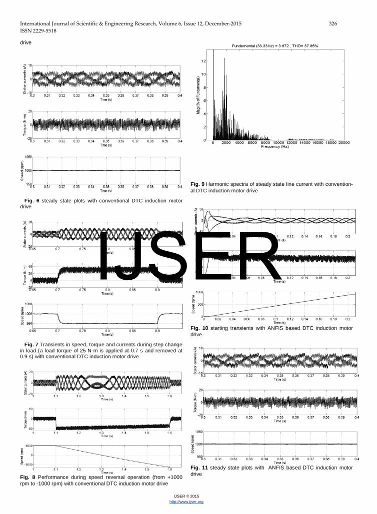
drive
Fig. 6 steady state plots with conventional DTC induction motor drive
Fig. 7 Transients in speed, torque and currents during step change in load (a load torque of 25 N-m is applied at 0.7 s and removed at 0.9 s) with conventional DTC induction motor drive
Fig. 8 Performance during speed reversal operation (from +1000 rpm to -1000 rpm) with conventional DTC induction motor drive
Fig. 9 Harmonic spectra of steady state line current with convention-al DTC induction motor drive
Fig. 10 starting transients with ANFIS based DTC induction motor drive
Fig. 11 steady state plots with ANFIS based DTC induction motor drive
IJSER

International Journal of Scientific & Engineering Research, Volume 6, Issue 12, December-2015 327 ISSN 2229-5518
IJSER © 2015 http://www.ijser.org
Fig. 12 Transients in speed, torque and currents during step change in load (a load torque of 25 N-m is applied at 0.7 s and removed at 0.9 s) with ANFIS based DTC induction motor drive
Fig. 13 Performance during speed reversal operation (from +1000 rpm to -1000 rpm) with ANFIS based DTC induction motor drive
Fig. 14 Harmonic spectra of steady state line current with ANFIS based DTC induction motor drive
6 CONCLUSION
The proposed ANFIS based induction motor drive is providing better performance when compared to conventional algorithm. The proposed controller is evaluated under simulations for a variety of operating conditions of the drive system and results demonstrate the effectiveness of these control structures to improve the performance of the drive system. It uses the instantaneous errors in d-and q axes stator currents and sector information to select the suitable voltage vector. Hence, the proposed algorithm uses a predetermined switching table instead of a much more time consuming PWM procedure in conventional FOC algorithm. From the simulation results it can be observed that when there is a step change in the load torque, the momentary decrease in speed with the proposed method is less. Finally the proposed method will provide less THD in steady state current ripple when compared to the conventional DTC algorithm.
REFERENCES
[1] Isao Takahashi, Toshihiko Noguchi, “A new quick-response and
high-efficiency control strategy of an induction motor”, IEEE Trans Ind Appl, Vol.IA-22, No.5, Sep/Oct, 1986, pp 820-827
[2] James N. Nash, “Direct torque control, Induction motor vector control without an encoder” IEEE Trans on Ind Appl., Vol 33, No.2, March/April 1997, pp 333-341.
[3] G. Escobar, A.M. Stancivić, E. Galvan, J.M. Carrasco and R. Orgeta, “A family of switching control strategies for the reduc-tion of torque ripple in DTC” IEEE Trans. Control Systems Tech., vol. 11, no. 6, Nov 2003, pp. 933-939.
[4] Joon Hyoung Ryu, Kwang Won Lee and Ja Sung Lee, “A unified flux and torque control method for DTC-based induction – mo-tor drives” IEEE Trans. Power Electron., vol.21, no.1, Jan 2006, pp.234-242.
[5] A. Damiano, G. Gatto, I. Marongiu and A. Perfetto, “An im-proved multilevel DTC drive” in IEEE proc. PESC, 2001, pp.1452-1457.
[6] José Rodríguez, Jorge Pontt, Samir Kouro and Pablo Correa, “Direct torque control with imposed switching frequency in an 11 – level cascaded inverter” IEEE Trans. Ind. Electron., vol. 51, no. 4, Aug 2004, pp. 827-833.
[7] S-G Cao, N. W. Rees, and G. Feng, 1999, “Analysis and de-sign of fuzzy control systems using dynamic fuzzy state spac-emodels,” IEEE Transactions on Fuzzy Systems, Vol. 7, No. 2, pp. 192–199.
[8] M. DENA¨I S. A. ATTIA, 2002,” Intelligent Control of and In-duction Motor,” Electrical Power Components and Systems, Vol.30, Issue.4, PP, 409-427.
[9] Fatiha Zidani and Rachid Naït Saïd, “Direct torque control of induction motor with fuzzy minimization torque ripple” Journal of Electrical Engineering, vol. 56, no. 7-8, 2005, pp. 183-188.
[10] Mr.T.Bheemeswara Reddy, Dr. K. Satyanarayana and T. Hima-ja “Modeling and Analysis of Adaptive Neuro Fuzzy Inference System Based BLDC Motor under Different Operating Condi-tions” in International Journal of Engineering and Advanced Technology Volume-3 Issue-6, August 2014.
IJSER