AN IMPROVED METHOD FOR DESIGN OF EXPANSION … · AN IMPROVED METHOD FOR DESIGN OF...
74
NASA TECHNICAL NOTE CO A NASA TN D-7309 AN IMPROVED METHOD FOR DESIGN OF EXPANSION-CHAMBER MUFFLERS WITH APPLICATION TO AN OPERATIONAL HELICOPTER by Tony L. Parrott Langley Research Center Hampton, Va. 23665 NATIONAL AERONAUTICS AND SPACE ADMINISTRATION • WASHINGTON, D. C. • OCTOBER 1973 https://ntrs.nasa.gov/search.jsp?R=19730022891 2018-06-08T00:49:59+00:00Z
Transcript of AN IMPROVED METHOD FOR DESIGN OF EXPANSION … · AN IMPROVED METHOD FOR DESIGN OF...

NASA TECHNICAL NOTE
CO
A NASA TN D-7309
AN IMPROVED METHOD FOR DESIGNOF EXPANSION-CHAMBER MUFFLERSWITH APPLICATION TOAN OPERATIONAL HELICOPTER
by Tony L. Parrott
Langley Research CenterHampton, Va. 23665
NATIONAL AERONAUTICS AND SPACE ADMINISTRATION • WASHINGTON, D. C. • OCTOBER 1973
https://ntrs.nasa.gov/search.jsp?R=19730022891 2018-06-08T00:49:59+00:00Z
1. Report No.
NASA TN D-73092. Government Accession No.
4. Title and SubtitleAN IMPROVED METHOD FOR DESIGN OF EXPANSION-CHAMBER MUFFLERS WITH APPLICATION TO ANOPERATIONAL HELICOPTER
7. Author(s)
Tony L. Parrott
9. Performing Organization Name and Address
NASA Langley Research Center
Hampton, Va. 23665
12. Sponsoring Agency Name and Address
National Aeronautics and Space AdministrationWashington, D.C. 20546
15. Supplementary Notes
3. Recipient's Catalog No. .
5. Report DateOctober 1973
6. Performing Organization Code
8. Performing Organization Report No.
L-8888
10. Work Unit No.
501-24 -Oi-0111. Contract or Grant No.
13. Type of Report and Period Covered
Technical Note
14. Sponsoring Agency Code
16. Abstract
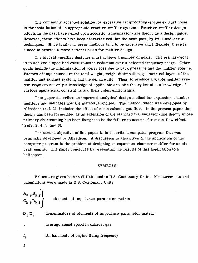
An improved method for the design of expansion- chamber mufflers is described andapplied to the task of reducing exhaust noise generated by a helicopter. The method is animprovement of standard transmission-line theory in that it accounts for the effect of themean exhaust-gas flow on the acoustic-transmission properties of a muffler system,including the termination boundary condition. The method has been computerized, and thecomputer program includes an optimization procedure that adjusts muffler component lengthsto achieve a minimum specified desired transmission loss over a specified frequency range.A printout of the program is included together with a user-oriented description.
A field test of a muffler designed with the aid of this method was conducted on a heli-copter with a known exhaust-noise problem. When the exhaust noises of the helicopter with astandard exhaust system and a similar helicopter with a muffler system installed were com-pared for hover flight conditions, the muffler system was found to reduce the exhaust noise byapproximately 11 dB(A). No significant degradation in the engine performance was observed.
17. Key Words (Suggested by Author(s))
Muffler design
Expansion chamber
Mean-flow effects
Computer program19. Security Oassif. (of this report)
Unclassified
18. Distribution Statement
Unclassified - Unlimited
20. Security Classif . (of this page)
Unclassified
21. No. of Pages 22. Price*Domestic, $3.50
71 Foreign, $&.00
For sale by the National Technical Information Service, Springfield, Virginia 22151

AN IMPROVED METHOD FOR DESIGN OF EXPANSION-CHAMBER
MUFFLERS WITH APPLICATION TO
AN OPERATIONAL HELICOPTER
By Tony L. ParrottLangley Research Center
SUMMARY
An improved method for the design of expansion-chamber mufflers is described andapplied to the task of reducing exhaust noise generated by a helicopter. The method is animprovement of standard transmission-line theory in that it accounts for the effect of themean exhaust-gas flow on the acoustic-transmission properties of a muffler system,including the termination boundary condition. The method has been computerized, andthe computer program includes an optimization procedure that adjusts muffler componentlengths to achieve a minimum specified desired transmission loss over a specified fre-quency range. A printout of the program is included together with a user-orienteddescription.
A field test of a muffler designed with the aid of this method was conducted on ahelicopter with a known exhaust-noise problem. When the exhaust noises of the helicopterwith a standard exhaust system and a similar helicopter with a muffler system installedwere compared for hover flight conditions, the muffler system was found to reduce theexhaust noise by approximately 11 dB(A). No significant degradation in the engine per-formance was observed.
INTRODUCTION
There is an increasing awareness of noise pollution on the part of the general public,especially noise caused by aircraft. In particular, users of certain types of general avia-tion aircraft may be compelled to restrict operations and/or modify their aircraft to com-ply with existing or forthcoming noise legislation that will specify upper limits on externalnoise levels (ref. 1). In addition, measurements have indicated that internal noise levelsof 11 light, twin-engine, fixed-wing aircraft exceed the currently accepted damage-riskcriterion for hearing loss. Analysis of this noise indicated that engine-exhaust noise wasthe primary cause of both unacceptably high cabin-noise levels and radiated far-fieldnoise (ref. 2). ,
The commonly accepted solution for excessive reciprocating-engine exhaust noiseis the installation of an appropriate reactive-muffler system. Reactive-muffler designefforts in the past have relied upon acoustic-transmission-line theory as a design guide.However, these efforts have been characterized, for the most part, by trial-and-errortechniques. Since trial-and-error methods tend to be expensive and inflexible, there isa need to provide a more rational basis for muffler design.
The aircraft-muffler designer must achieve a number of goals. The primary goalis to achieve a specified exhaust-noise reduction over a selected frequency range. Othergoals include the minimization of power loss due to back pressure and the muffler volume.Factors of importance are the total weight, weight distribution, geometrical layout of themuffler and exhaust system, and the service life. Thus, to produce a viable muffler sys-tem requires not only a knowledge of applicable acoustic theory but also a knowledge ofvarious operational constraints and their interrelationships.
This paper describes an improved analytical design method for expansion-chambermufflers and indicates how the method is applied. The method, which was developed byAlfredson (ref. 3), includes the effect of mean exhaust-gas flow. In the present paper thetheory has been formulated as an extension of the standard transmission-line theory whoseprimary shortcoming has been thought to be the failure to account for mean-flow effects
'(refs. 3, 4, 5, and 6).
The second objective of this paper is to describe a computer program that wasoriginally developed by Alfredson. A discussion is also given of the application of thecomputer program to the problem of designing an expansion-chamber muffler for an air-craft engine. The paper concludes by presenting the results of this application to ahelicopter.
SYMBOLS
Values are given both in SI Units and in U.S. Customary Units. Measurements andcalculations were made in U.S. Customary Units.
Ak,j'Bk,j' telements of impedance-parameter matrix
denominators of elements of impedance-parameter matrix
average sound speed in exhaust gas
ith harmonic of engine firing frequency
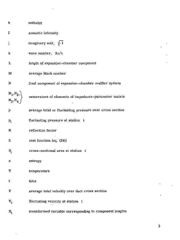
h enthalpy
I acoustic intensity
j imaginary unit, \ML
k wave number, 2-n/X
L length of expansion-chamber component
M average Mach number
N final component of expansion-chamber muffler system
N1'N2'1> numerators of elements of impedance-parameter matrixN3'N4j
p average total or fluctuating pressure over cross section
p^ fluctuating pressure at station i
R reflection factor
S cost function (eq. (29))
Sj cross-sectional area at station i
s entropy
T temperature
t time
V average total velocity over duct cross section
Vj fluctuating velocity at station i
X^ transformed variable corresponding to component lengths

Z specific acoustic impedance
y ratio of specific heats
6 irreversible pressure loss
X wavelength
II series multiplication
p mass density of exhaust medium
S series summation
(p phase angle between incident and reflected wave
w circular frequency
Subscripts:
b branch pipe
f presence of mean flow
i station designation, matrix-element index
k,j identification of impedance-parameter element
o stagnation value
t termination value
Superscripts:
(+) wave propagating in forward direction
(-) wave propagating in negative direction

Notation:
amplitude of fluctuating quantity
— normalization by pc
Abbreviations:
dB sound pressure level in decibels (ref. 0.0002 dyne/cm2)
dB(A) A-weighted sound pressure level (ref. 0.0002 dyne/cm2)
MAP manifold pressure
PWL acoustic power level
TL acoustic transmission loss
MUFFLER DESIGN METHOD
Review of Transmission-Line Theory
An improved muffler design method has been developed which is an extension oftransmission-line theory to include the effects of flow, termination impedance, extendedinlet and outlet pipes, and yielding walls. The details underlying the development of thismethod are given in references 3, 4, and 5. In this section the method is describedthrough the use of the concepts of transmission-line theory. Then, in the following sec-tion a description of the computer program and its use will be given. The reader con-cerned only with the application of the computer program may proceed to the section"Computer Program" without loss of continuity.
The application of the electrical transmission-line analogy to acoustic filter designwas successfully accomplished in this country by Stewart in 1923 (as discussed in ref. 7).The applicability of this design tool to mufflers for reciprocating engines used in aircraftwas investigated experimentally in the early fifties by Davis, Stokes, Moore, and Stevens(ref. 6). Original.credit for the development of the transfer-matrix approach to four-terminal (or two-port) physical systems is due to Strecker and Feldtkeller (ref. 8). The'widespread use of the transfer-matrix approach in mechanical, fluid, and thermal sys-tems is largely due to the contributions of Pipes (ref. 9). In Japan this approach wasextended to engine-exhaust muffler systems by Igarashi, Toyama, Miwa, and Arai(refs. 10, 11, and 12). Although transmission-line theory is well developed, it is of
interest to review briefly the fundamental ideas and assumptions of this theory to placein better perspective the improved design method discussed in this paper.
The key assumptions underlying transmission-line theory in its simplest applica-tion to muffler design are
(1) Fluctuating pressures are small relative to the average pressure in the system.
(2) The duct and muffler walls are rigid.
(3) Only plane waves are propagated (i.e., p'^ = ±pcV^±'J.
(4) The temperature of the medium is constant with time and spatially uniformthroughout the muffler.
(5) The average velocity of the medium is zero.
(6) Viscosity effects at the duct and muffler walls are negligible.
(7) Fluctuating quantities are decomposable into sinusoidal components of the form
pel"*.
Operating principle.- Reactive mufflers, of which expansion chambers are a specialcase, function by causing reflected waves to be propagated back toward the acousticsource. In the case of expansion chambers, these reflected waves are generated byabrupt changes of cross-sectional area. The objective in design of expansion-chambermufflers is to arrange combinations of duct area changes in the most propitious way forreflecting acoustic energy back into the source over the desired frequency range. Thesimplest practical expansion-chamber muffler is shown in figure 1. It consists of twocross-sectional-area changes separated by a length L. The amount of acoustic energyassociated with the reflected pressure wave p/' is a function of the cross-sectionalarea ratio 82/81, whereas the length L determines the acoustic frequency at which themaximum reflection occurs.
Muffler performance.- The ratio of fluctuating pressure to fluctuating volume veloc-ity of a forward-going plane wave averaged over a duct cross section through which thewave is propagating is a useful quantity for describing the noise-reduction performanceof a reactive-muffler system and is called the analogous characteristic acoustic impedanceof the duct, or simply the characteristic impedance when the meaning is clear from thecontext. At an isolated discontinuity in duct area, the change in characteristic impedanceof the duct is related to the amount of acoustic energy reflected at the discontinuity. Thetotal impedance change associated with a series of discontinuities may be calculated froman appropriate set of boundary conditions relating fluctuating quantities across the dis-continuities, or it may be determined from laboratory tests. When all the impedancechanges in a muffler system are known, the input impedance at the muffler inlet may becalculated by starting at the tailpipe and working systematically backward to the inlet. If
the source impedance is known, the total radiated power of the system may be determinedand compared with the radiated power before the muffler system is attached. This com-parison is accomplished by taking the ratio of the radiated power before the muffler isattached to that after the muffler is attached. This ratio is called the insertion loss ofthe muffler system, in analogy with the electrical filter theory. The insertion loss, as afunction of frequency, completely characterizes a muffler system insofar as its noise-reducing ability is concerned.
Source-impedance effects.- If the amplitude of the incident wave arriving at themuffler inlet from the source is equal to the amplitude of the incident wave when themuffler system is absent, then the source is said to be nonreflecting and the effectivesource impedance is equal to the duct impedance. For reciprocating-engine exhaust sys-tems in general, this condition seems unlikely to hold for all frequencies of interest; how-ever, experimental and/or analytical studies to date have not provided reliable informationon source impedance. In its absence, the muffler-system designer is forced to rely ontransmission loss as a measure of muffler-system performance.
Transmission loss.- Transmission loss is the ratio of the incident acoustic powerto the transmitted power through the muffler. It is a single number (for each frequencyof interest) and does not permit the prediction of acoustic performance of a completeengine and exhaust muffler system. Furthermore, transmission loss is not directly mea-surable and is influenced by the termination boundary condition. Its advantages are thatit is conceptually simple and does provide a figure of merit when comparing muffler sys-tems with identical terminations, hence the traditional propensity for its use. Also, tothe extent that the source can be considered nonreflecting, the transmission loss is anindication of the insertion loss to be expected.
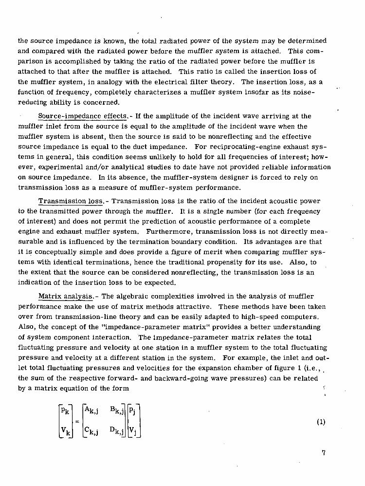
Matrix analysis.- The algebraic complexities involved in the analysis of mufflerperformance make the use of matrix methods attractive. These methods have been takenover from transmission-line theory and can be easily adapted to high-speed computers.Also, the concept of the "impedance-parameter matrix" provides a better understandingof system component interaction. The impedance-parameter matrix relates the totalfluctuating pressure and velocity at one station in a muffler system to the total fluctuatingpressure and velocity at a different station in the system. For example, the inlet and out-let total fluctuating pressures and velocities for the expansion chamber of figure 1 (i.e.,the sum of the respective forward- and backward-going wave pressures) can be relatedby a matrix equation of the form
(1)_vk=
Ak,j Bk,j
ck i Dk i_ K.,1 ^ti_
V
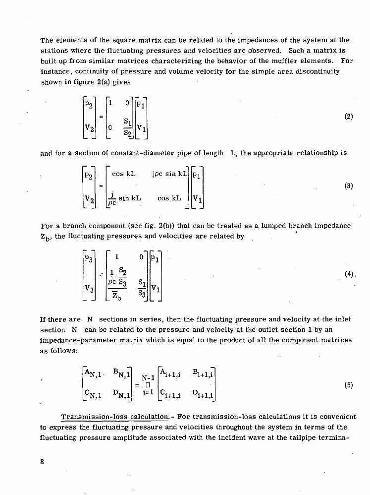
The elements of the square matrix can be related to the impedances of the system at thestations where the fluctuating pressures and velocities are observed. Such a matrix isbuilt up from similar matrices characterizing the behavior of the muffler elements. Forinstance, continuity of pressure and volume velocity for the simple area discontinuityshown in figure 2(a) gives
(2)
and for a section of constant-diameter pipe of length L, the appropriate relationship is
P2
!2_
1 0
si° 4PI
Jl
P2 cos kL jpc sin kL
— sin kL cos kLpc
Pi(3)
For a branch component (see fig. 2(b)) that can be treated as a lumped branch impedanceZ,, the fluctuating pressures and velocities are related by
pcS3
0
S3
PI
Vl
(4),
If there are N sections in series, then the fluctuating pressure and velocity at the inletsection N can be related to the pressure and velocity at the outlet section 1 by animpedance-parameter matrix which is equal to the product of all the component matricesas follows:
AN,1 BN,1
CN,1 DN,1
N-l= n (5)
Transmission-loss calculation.- For transmission-loss calculations it is convenientto express the fluctuating pressure and velocities throughout the system in terms of thefluctuating pressure amplitude associated with the incident wave at the tailpipe termina-
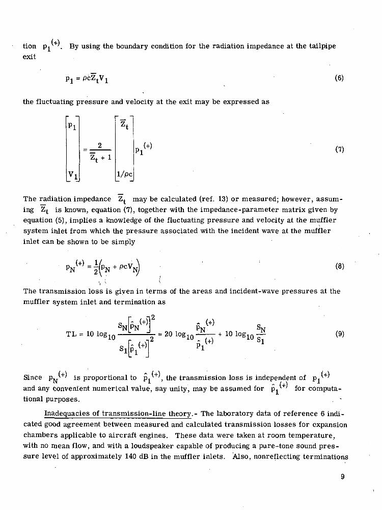
tion PI . By using the boundary condition for the radiation impedance at the tailpipeexit
(6)
the fluctuating pressure and velocity at the exit may be expressed as
PI
1/pc
PI (7)
The radiation impedance Z^ may be calculated (ref. 13) or measured; however, assum-ing Z^ is known, equation (7), together with the impedance-parameter matrix given byequation (5), implies a knowledge of the fluctuating pressure and velocity at the mufflersystem inlet from which the pressure associated with the incident wave at the mufflerinlet can be shown to be simply
PN (+) = (8)
The transmission loss is given in terms of the areas and incident-wave pressures at themuffler system inlet and termination as
TL = 10 log 10 (9)
Pi , the transmission loss is independent of Pifor computa-
Since PJT is proportional toand any convenient numerical value, say unity, may be assumed fortional purposes.
Inadequacies of transmission-line theory.- The laboratory data of reference 6 indi-cated good agreement between measured and calculated transmission losses for expansionchambers applicable to aircraft engines. These data were taken at room temperature,with no mean flow, and with a loudspeaker capable of producing a pure-tone sound pres-sure level of approximately 140 dB in the muffler inlets. Also, nonreflecting terminations
9

were used for the muffler outlets. When similar mufflers were tested on an aircraftengine, the exhaust-noise reduction fell short of that predicted from the transmission-loss calculations (ref. 6). The authors of reference 6 believed that the discrepancieswere related to mean-flow effects and the violation of the small-amplitude assumption oflinear acoustics. The recent work reported in references 3, 4, 5, and 14 suggested thatfor expansion- chamber mufflers, the nonlinear effect due to large acoustic pressures wasnegligible for design purposes. Further investigations reported in references 3, 4, and 5suggested that the effect of mean gas flow on the termination boundary condition and otherimpedance discontinuities was the most significant factor neglected in the standardtransmission-line theory. Consequently, mean-flow effects were included in the analysisof expansion- chamber performance. The results of this analysis will be summarized inthe following section.
Effect of Mean Gas Flow on Muffler Performance
The improved muffler design method described herein involves the effect of themean flow on the impedance changes at duct-area and branch discontinuities. Also, theeffect on the tailpipe termination impedance is included. The effect of flow on the inter-nal impedance changes is a straightforward extension of transmission-line theory usingthe linearized equations for energy, mass, and in some cases momentum conservationacross area discontinuities. The single most significant effect of the flow is associatedwith the radiation characteristics of the tailpipe.
Tailpipe radiation.- In a duct with a termination characterized by the unflanged-pipereflection factor R, the relation between the incident-wave pressure amplitude p^+' andthe reflected-wave pressure amplitude jr' is given by
(10)
where <p is the phase angle between the incident and reflected wave. Thus the netintensity in the pipe is given by
i = J i L - L i . R 2 '
where p^+' is the pressure amplitude of the forward-going wave. For a mean flow withMach number M, the acoustic intensity becomes
-J-fl + M)2 - (1 - M)2 R2(M)|pc L J
If = i- (1 + M)* - (1 - M)' R*(M) (12)1 2pc ' '
10
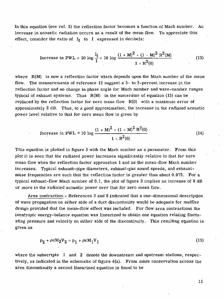
In this equation (see ref. 3) the reflection factor becomes a function of Mach number. Anincrease in acoustic radiation occurs as a result of the mean flow. To appreciate thiseffect, consider the ratio of If to I expressed in decibels:
increase in PWL = 10 log = 10 log (13), 1 - R2(0)
where R(M) is now a reflection factor which depends upon the Mach number of the meanflow. The measurements of reference 12 suggest a 3- to 5 -percent increase in thereflection factor and no change in phase angle for Mach number and wave-number rangestypical of exhaust systems. Thus R(M) in the numerator of equation (13) can bereplaced by the reflection factor for zero mean flow R(0) with a maximum error ofapproximately 2 dB. Thus, to a good approximation, the increase in the radiated acousticpower level relative to that for zero mean flow is given by
(1 + M)2 - (1 - M)2 R2(0)Increase in PWL ~ 10 log - (14)
1 - R2(0)
This equation is plotted in figure 3 with the Mach number as a parameter. From thisplot it is seen that the radiated power increases significantly relative to that for zeromean flow when the reflection factor approaches 1 and as the mean-flow Mach numberincreases. Typical exhaust-pipe diameters, exhaust-gas sound speeds, and exhaust-noise frequencies are such that the reflection factor is greater than about 0.975. For atypical exhaust-flow Mach number of 0.1, the plot of figure 3 implies an increase of 8 dBor more in the radiated acoustic power over that for zero mean flow.
Area contraction.- References 3 and 5 indicated that a one-dimensional descriptionof wave propagation on either side of a duct discontinuity would be adequate for mufflerdesign provided that the mean-flow effect was included. For flow area contractions theisentropic energy-balance equation was linearized to obtain one equation relating fluctu-ating pressure and velocity on either side of the discontinuity. This resulting equation isgiven as
P2 + pcM2V2 = PI + pcMjVi (15)
where the subscripts 1 and 2 denote the downstream and upstream stations, respec-tively, as indicated in the schematic of figure 4(a). From mass conservation across thearea discontinuity a second linearized equation is found to be
11
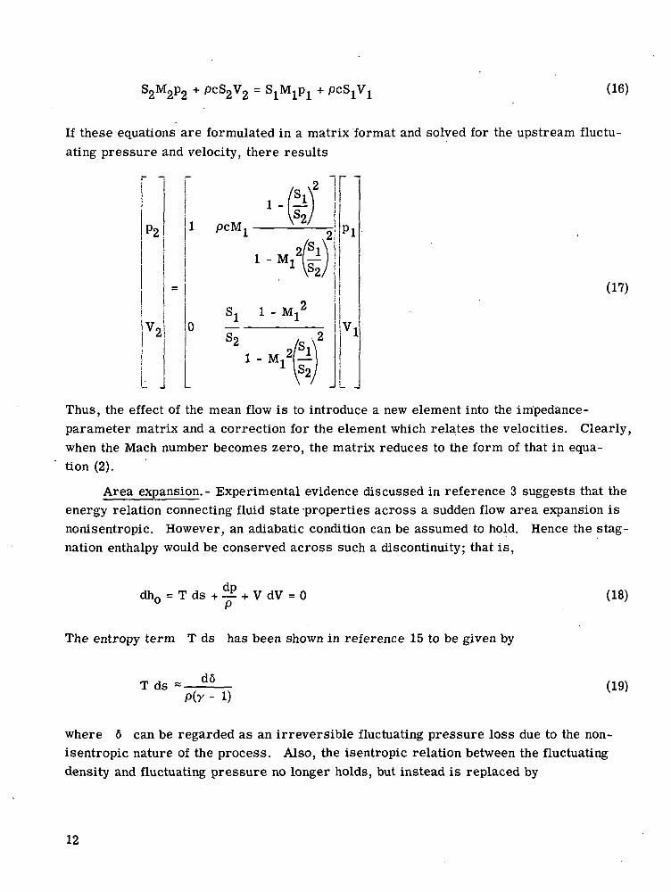
+ PcS2V2 = (16)
If these equations are formulated in a matrix format and solved for the upstream fluctu-ating pressure and velocity, there results
P2
V2
/Slf 1
1 orM 'A 0
O/ 1 i '
S< 1 - Mj2
o82 /o \2
/s \1 _ M,2)— )
I So /\ /
Pi
Vl
(17)
Thus, the effect of the mean flow is to introduce a new element into the impedance-parameter matrix and a correction for the element which relates the velocities. Clearly,when the Mach number becomes zero, the matrix reduces to the form of that in equa-tion (2).
Area expansion.- Experimental evidence discussed in reference 3 suggests that theenergy relation connecting fluid state -properties across a sudden flow area expansion isnonisentropic. However, an adiabatic condition can be assumed to hold. Hence the stag-nation enthalpy would be conserved across such a discontinuity; that is,
dhn = T ds + -^ + V dV = 0 (18)
The entropy term T ds has been shown in reference 15 to be given by
T d s « -P(y - D
(19)
where 6 can be regarded as an irreversible fluctuating pressure loss due to the non-isentropic nature of the process. Also, the isentropic relation between the fluctuatingdensity and fluctuating pressure no longer holds, but instead is replaced by
12

(20)
By using the relation (19), equation (18) can be integrated across the discontinuity fromthe downstream to the upstream side, as indicated in the schematic of figure 4(b). Thereresults after linearization
y - 1(21)
From mass conservation and the use of equation (20) to eliminate the fluctuating density,
+ PcS2V2 = (22)
Because of the introduction of the unknown quantity 6, a third equation must be derived.This can be obtained from momentum conservation across the discontinuity, which givesafter linearizing and the use of equation (20)
(23)0\ /
j + S2M2 Jp2 + 2pcS2M2V2 = (Sj
where the momentum source term due to the discontinuity has been taken to bep2(Si - S2), which is based on experimental evidence indicated in reference 3. When this
equation is solved for 6 and substituted into equations (21) and (22), the upstream fluc-tuating pressure and velocity can again be related to the corresponding downstreamquantities by an impedance-parameter matrix whose elements are given by
1 +'si\ ST-i < y - l ) - 2 y - i + yb2 b2
Mi
(24a)
B,. , =
SlS^
(24b)
13

1
pciwrM
(24c)
D,. • = (24d)
where
( y - l ) - - (24e)
Again, these equations are seen to reduce to a form equivalent to equation (2) when theMach number approaches zero.
Area contraction with a branch. - Practical expansion-chamber mufflers usuallyhave extended inlet and outlet pipes, as shown in the schematic of figures 4(c) and (d).Such geometrical arrangements perform acoustically as a side branch with impedanceZb. The side branch is indicated as region (Y) in figures 4(c) and (d). The value of Zb,
which is specified at the junction of regions MA (If), and (V), is controlled by the rigidityof the end wall and by the branch length. The branch impedance Z^b is related to thereflection factor R^ and phase angle 0 at the branch entrance by the equation
Rbe
1 - Rb<
(25)
If the reflection factor and phase angle at the end cap are denoted by R and 4>, respec-tively, then RJ.J = R for no energy dissipation between the entrance and end cap. Also,$k = 0 - 2kL, where L is the branch length and the coordinate direction is that shownin figures 4(c) and (d). By the appropriate selection of the various branch lengths in amuffler system, the transmission-loss characteristic can be tailored to specificationswithin certain limits. For a branch impedance associated with a flow area contractionshown schematically in figure 4(c), the impedance-parameter matrix for the simple areacontraction can be generalized to include the branch impedance. The result is
14

/ \i Si So /S i \ o1 .-L-L-*Mi - — MI—— o C A \ o / A7 oo t>o \Oo;^h 6 6 \ 6J
PCS 1-Ui Mi + —— — Mi
- Ml
_S
(26)
Note that if Z^ approaches infinity (i.e., the end wall becomes rigid and the branchlength becomes zero), then the impedance-parameter matrix reduces to that of equa-tion (17). Furthermore, if the mean-flow Mach number approaches zero, then the resultbecomes equivalent to that of equation (4).
Area expansion with a branch. - If the muffler inlet pipe is extended, then a branchimpedance becomes associated with an area expansion. When this impedance is includedin the boundary condition for an area expansion, the elements for the impedance-parameter matrix relating upstream and downstream fluctuating pressures and velocitiesbecome
N +J-?i?21 Zb
S3 S3v * <^ - '>«3 Sj 4
1 ^Ml_
DI + D2
(27a)
D1 + D2
(27b)
No - —- _±3
CM = +D 2
(27c)
15

3
J
D,D2
(27d)
where Nj, N2, N3, and N^ are the respective numerators of equations (24a, b, c,and d), and Dj is given by equation (24e). The quantity D2 is associated with thebranch impedance Z^ and is given by
J_I2ZbS3
__ 2 MI + — (27e)
Again, when Z^ becomes large, these equations are seen to reduce to equations (24),as expected. It was found by the authors of references 4, 5, and 6 that yielding wallscould significantly affect muffler performance; consequently, in references 4 and 5 theimpedance of the end caps was altered in a trial-and-error procedure to force the mathe-matical models for the branched elements to conform with measurements. For a flowarea contraction the reflection factor and phase angle of the branch impedance at the endcap were taken as 0.8 and 0.01 radian, respectively, whereas for flow area expansion thereflection factor was taken to be 1.0 and the phase angle as 0.01 radian. The lowerreflection factor for area contraction was used because the isentropic flow conditionacross that type of discontinuity does not allow the occurrence of acoustic energy dissipa-tion, which in fact is known to exist but to a much lesser extent than for an expansion typeof discontinuity. This completes the formulations of the impedance-parameter matrixfor the various discontinuities encountered in a muffler system consisting of a series ofcascaded expansion chambers.
Finite-length section.- To relate the fluctuating pressure and velocity at theupstream side of a discontinuity to the fluctuating pressure and velocity at the down-stream side of the next discontinuity joined by a constant-diameter duct (see fig. 5) car-rying a mean flow with Mach number M3, equation (3) is modified as follows:
16
P4 cos jpc sin.
kL
\1 - M3'
PS
(28)
Clearly, for the typical mean-flow Mach numbers of 0.1 encountered in exhaust systems,this correction is relatively insignificant.
Model comparisons.- Figure 6 shows a comparison of transmission loss calculatedby the theoretical model described in this paper with the standard transmission-linetheory discussed in reference 6. The muffler configuration chosen for illustrative pur-poses is shown in the sketch in the figure along with relevant geometrical data. Note thatthere is a significant reduction of transmission loss in the frequency range 200 to 350 Hzdue to both the mean-flow effects and the yielding end cap (reflection factor 0.8 for flowarea contraction). On the other hand there is an increase in transmission loss above350 Hz over that for no mean flow.
COMPUTER PROGRAM
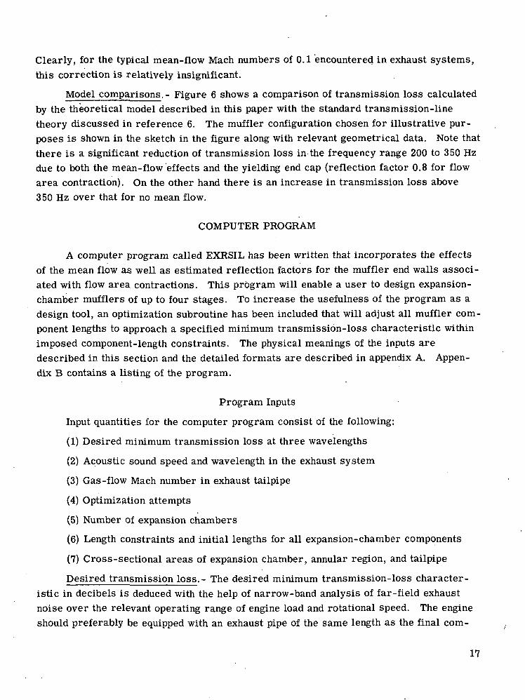
A computer program called EXRSIL has been written that incorporates the effectsof the mean flow as well as estimated reflection factors for the muffler end walls associ-ated with flow area contractions. This program will enable a user to design expansion-chamber mufflers of up to four stages. To increase the usefulness of the program as adesign tool, an optimization subroutine has been included that will adjust all muffler com-ponent lengths to approach a specified minimum transmission-loss characteristic withinimposed component-length constraints. The physical meanings of the inputs aredescribed in this section and the detailed formats are described in appendix A. Appen-dix B contains a listing of the program.
Program Inputs
Input quantities for the computer program consist of the following:
(1) Desired minimum transmission loss at three wavelengths
(2) Acoustic sound speed and wavelength in the exhaust system
(3) Gas-flow Mach number in exhaust tailpipe
(4) Optimization attempts
(5) Number of expansion chambers
(6) Length constraints and initial lengths for all expansion-chamber components
(7) Cross-sectional areas of expansion chamber, annular region, and tailpipe
Desired transmission loss.- The desired minimum transmission-loss character-istic in decibels is deduced with the help of narrow-band analysis of far-field exhaustnoise over the relevant operating range of engine load and rotational speed. The engineshould preferably be equipped with an exhaust pipe of the same length as the final com-
17
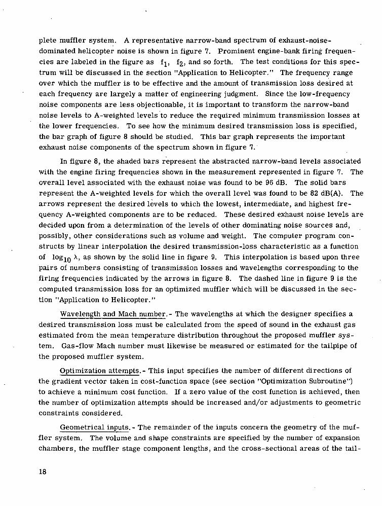
plete muffler system. A representative narrow-band spectrum of exhaust-noise-dominated helicopter noise is shown in figure 7. Prominent engine-bank firing frequen-cies are labeled in the figure as fj, f2, and so forth. The test conditions for this spec-trum will be discussed in the section "Application to Helicopter." The frequency rangeover which the muffler is to be effective and the amount of transmission loss desired ateach frequency are largely a matter of engineering judgment. Since the low-frequencynoise components are less objectionable, it is important to transform the narrow-bandnoise levels to A-weighted levels to reduce the required minimum transmission losses atthe lower frequencies. To see how the minimum desired transmission loss is specified,the bar graph of figure 8 should be studied. This bar graph represents the importantexhaust noise components of the spectrum shown in figure 7.
In figure 8, the shaded bars represent the abstracted narrow-band levels associatedwith the engine firing frequencies shown in the measurement represented in figure 7. Theoverall level associated with the exhaust noise was found to be 96 dB. The solid barsrepresent the A-weighted levels for which the overall level was found to be 82 dB(A). Thearrows represent the desired levels to which the lowest, intermediate, and highest fre-quency A-weighted components are to be reduced. These desired exhaust noise levels aredecided upon from a determination of the levels of other dominating noise sources and,possibly, other considerations such as volume and weight. The computer program con-structs by linear interpolation the desired transmission-loss characteristic as a functionof logjQ X, as shown by the solid line in figure 9. This interpolation is based upon threepairs of numbers consisting of transmission losses and wavelengths corresponding to thefiring frequencies indicated by the arrows in figure 8. The dashed line in figure 9 is thecomputed transmission loss for an optimized muffler which will be discussed in the sec-tion "Application to Helicopter."
Wavelength and Mach number.- The wavelengths at which the designer specifies adesired transmission loss must be calculated from the speed of sound in the exhaust gasestimated from the mean temperature distribution throughout the proposed muffler sys-tem. Gas-flow Mach number must likewise be measured or estimated for the tailpipe ofthe proposed muffler system.
Optimization attempts.- This input specifies the number of different directions ofthe gradient vector taken in cost-function space (see section "Optimization Subroutine")to achieve a minimum cost function. If a zero value of the cost function is achieved, thenthe number of optimization attempts should be increased and/or adjustments to geometricconstraints considered.
Geometrical inputs.- The remainder of the inputs concern the geometry of the muf-fler system. The volume and shape constraints are specified by the number of expansionchambers, the muffler stage component lengths, and the cross-sectional areas of the tail-
18

pipe, chamber, and annulus. It should be noted that the cross-sectional areas cannot bevaried within a stage or between stages. There are four component lengths per mufflerstage as indicated in figure 10. Constraints on these lengths are specified independentlyfor each stage together with an initial length for each stage component.
Program Outputs
Program outputs are the following:
(1) Input data listing
(2) Computer-generated desired minimum transmission-loss characteristic
(3) Record of optimization attempts
(4) Optimized component lengths
(5) Computed transmission-loss characteristic
Input data listing.- This section of output simply tabulates the minimum, initial, andmaximum values of all component lengths working from the tailpipe to the inlet. Alsogiven are the cross-sectional areas and tailpipe Mach number.
Desired transmission loss.- The minimum desired transmission-loss character-istic is listed along with the frequency and wavelength as determined from the mean tem-perature of the exhaust gas.
Optimization attempts.- The next listing shows a record of the optimization attemptswhich consists of the cost functions and the corresponding component lengths at a partic-ular point in the optimization process: The message NEW POINT indicates the change ofdirection of the gradient vector in the cost-function space.
Optimized component lengths.- This listing shows the component lengths for thefinal configuration together with the final cost function.
Computed transmission loss..- This section of output lists the computed transmis-sion loss of the final configuration at the same wavelengths and frequencies as was donefor the desired transmission loss.
Engineering Judgments
Reduction of low-frequency exhaust noise generally deteriorates with decreasingexpansion-chamber length. Thus it is mandatory to establish the maximum muffler lengthavailable if low-frequency noise is a problem. Most practical muffler systems will incor-porate flow-reversing bends to achieve necessary compactness, as shown in the schematicof figure 10. The transmission loss of such bends is estimated to be less than 2 dB whentransmitting into a nonreflecting termination over the frequency range of interest in
19

reactive-muffler design. Thus, the effect of smooth bends should be relatively unimpor-tant for design purposes.
The muffler geometry also affects the back pressure at the engine exhaust ports.Since an increase in mean back pressure has been found to correlate roughly with degra-dation of multicylinder-engine performance, mean back pressure is conventionally usedas an indicator of possible loss in engine performance. Mean back pressure is minimizedin purely expansion-chamber mufflers by making bends as smooth as possible and byalining inlet and outlet pipes, as shown in figure 10. No attempt is made in this programto compute magnitude of mean back pressure.
All component-length constraints should be mutually consistent and compatible withthe space requirements. If some component lengths must be held constant, constraintsmust still be specified to bracket the initial length so that a significant variation cannotoccur. Maximum lengths of internal pipes should not be such that their separation is lessthan 1 pipe diameter and preferably 1 chamber diameter.
Optimization Subroutine
The transmission loss of a muffler system is treated by the optimization subroutineas a function of 4N variables, where N is the number of muffler stages. By systemati-cally changing the various component lengths and comparing the resulting transmissionlosses with the desired minimum transmission losses at 151 equally spaced values of thelogarithm of the wavelength, the subroutine attempts to minimize a cost function. Thiscost function is defined by
151 '
where (TL)d(Aj) is the desired transmission loss at the wavelength A^ and (TL)c(\j)is the computed transmission loss at the same wavelength for some given configuration.If (TL)d(\i) = (TL)c(\i) for a particular wavelength, then that term is omitted.
The cost-function independent variables 1^ must all have boxlike constraintsimposed on them, that is,
Lmin < Li < Lmax (30)
On the other hand, the optimization procedure must operate with independent variablesthat are unconstrained. This condition is fulfilled by defining a new set of variables Xjby means of the transformation
20

(31)
The details of the process by which the procedure systematically alters the com-ponent lengths are discussed in reference 3 and will not be given here; however, theprocess is basically a modification and extension of the steepest-descent method thatresults in an improved rate of convergence. From the user's standpoint, he can regardthe subroutine as a minimization process that operates by following a prescribed direc-tion vector in the cost-function space until a minimum is achieved; then the directionvector is changed or updated whereupon a search for a new minimum will begin. Thisevent is signified in the output listing by the heading NEW POINT. The number of newpoints (or optimization attempts) to be taken is set by the user by reading in a value ofthe integer variable NO, which is usually taken to be between 5 and 10. It is the natureof the optimization procedure to find the minimum cost function which is nearest the ini-tial configuration of component lengths. Since other more significant or preferable min-imums may exist, several different sets of initial configurations should be tried. At theend of the last minimum search, a normal return of control to the main program will beindicated by the message SEARCH COMPLETED, NORMAL RETURN.
This completes the description of the computer program and its use. In theremainder of this paper an evaluation of the results obtained upon applying the programto the design of a muffler for a helicopter will be given.
APPLICATION TO HELICOPTER
The purpose of this section is to describe the design and to present the measurednoise-reduction performance of a muffler for a helicopter engine exhaust. The mufflerdesign was accomplished with the aid of the previously described computer program.
Apparatus and Methods
Test helicopter.- A photograph of the test helicopter for which a muffler systemwas designed is shown in figure 11. The physical characteristics are given in table I.The aircraft was powered by a six-cylinder, horizontally opposed engine. The exhaustgases from each bank of three cylinders are routed through a manifold and then out astraight stack to the side and rear of the helicopter, as shown in the photograph of fig-
Nc x rot. speedure 12. The engine fundamental firing frequency is defined to be — for a
120four-stroke operating cycle, where Nc is the number of cylinders. For the manifold
21
geometry of this particular engine, it was convenient to correlate the exhaust noise com-ponents with harmonics of the engine-bank fundamental firing frequency, in which caseNc was taken as 3.
Acoustic measurements.- Initial base-line acoustic measurements were conductedfor the helicopter with the engine equipped with the standard exhaust manifold systemshown by the photograph of figure 12 and hereinafter called the standard helicopter. Theacoustic signals emitted by the helicopter were measured with commercially available,piezoelectric, ceramic-type microphones and were recorded by a multichannel, frequency-modulated tape recorder at a tape speed of 0.76 m/sec (30 in/sec) and a center frequencyof 54 kHz. The frequency response of the complete measurement system was within 3 dBover the frequency range 12 Hz to 12 kHz.
The microphones were positioned at a radius of 30.5 m (100 ft) from the aircraftevery 18° over one quadrant. A complete 360° noise survey of the helicopter noise wasobtained by hovering the helicopter first at 0°, then 90°, 180°, and finally at 270°. Themeasurements were conducted over flat terrain at the approach end of runway 17 atLangley Air Force Base.
Muffler Design and Installation
Design procedure.- The computerized analytical muffler design method and requiredengineering judgments have already been described elsewhere in this report. In this sec-tion specific design considerations for the test helicopter will be discussed.
Weight and volume limitations indicated that a single muffler that would handle theexhausts from both engine banks would be preferable to*a muffler for each bank. Also,it was anticipated that the Y-connector used for combining the two streams of engineexhaust gas would provide some noise reduction of the engine odd-harmonic firing fre-quencies and some amplification of the engine even-harmonic firing frequencies. Thispossibility permitted a muffler design with a less demanding transmission-loss perform-ance at the engine-bank fundamental firing frequency. This relaxed performance require-ment is evidenced by the 9 dB desired minimum transmission loss at the engine-bankfundamental firing frequency indicated by the arrow in figure 8.
Back-pressure considerations.- Engine back pressure produced by the muffler sys-tem was not computed or measured; however, an effort was made to minimize back pres-sure by making the total exhaust-pipe area as large as was practical. Also, the inlet andoutlet pipes in all the chambers were arranged so that the center lines coincided insofaras was practical. Finally, sudden flow-direction changes were avoided as much aspossible.
22

Muffler configuration.- The computer-generated component lengths and a sketch ofthe corresponding geometrical configuration are shown in figure 13. It is important tounderstand that the general configuration is determined by the designer. The designermust specify constraints on the overall lengths, cross-sectional areas, relative arrange-ment and number of chambers, and the handling of the internal flow. The computer pro-gram adjusts the various component lengths within imposed constraints to achieve asnearly as possible a desired transmission-loss characteristic. The configuration shownin figure 13 produces the transmission-loss characteristic shown by the dashed line infigure 9, which compares favorably with the minimum desired transmission-loss char-acteristic shown by the solid line in figure 9. The muffler system was designed to pro-duce an exhaust-noise reduction of 15 to 20 dB(A).
Installation.- The installation of the Y-connector and muffler is shown in figures 14and 15, respectively. The exhaust gases were combined with the Y-connector then ledinto the muffler inlet, as shown in figure 15. This particular mounting arrangementallowed minimum disturbance of the aircraft weight balance and prevented operatingproblems relative to the high-temperature exposed surfaces. The muffler volume was0.057 m3 (2.0 ft3) and the weight of the entire system was 21.3 kg (47 Ib).
Results and Discussion
Exhaust-noise reduction.- Total radiated noise from the helicopter was measuredwith the muffler system installed (hereinafter called the modified helicopter) as was donefor the standard helicopter configuration. The narrow-band (4-Hz) spectrum of the noisefrom the modified helicopter is shown.in figure 16 by the solid curve, and the narrow-bandspectrum for the standard helicopter from figure 7 is shown superimposed in figure 16 bythe dashed line to facilitate evaluation of the muffler-system effectiveness. Clearly, thedominant components of the exhaust noise have been eliminated. At the low frequencies,rotor noise now appears to dominate the spectrum. In the higher frequency range, 320 to520 Hz, there is a 3 to 5 dB increase in the spectrum floor which may be attributable toself-noise (see ref. 16) generated by the muffler system. The overall exhaust-noisereduction obtained was approximately 11 dB(A), whereas the desired reduction was 15 to20 dB(A).
Estimated muffler insertion losses.- The spectrum information shown in figure 7and similar data with the Y-connector only installed were used to estimate the insertionlosses of the muffler at the engine-bank firing frequencies. These insertion losses arelisted in the last column of table n. Also listed are the measured sound pressure levelsunder comparable test conditions corresponding to the standard exhaust system,Y-connector only, and Y-connector with muffler. From these tabulations the estimatedmuffler insertion losses were obtained. It is important to note that the listed insertion
23

losses are lower bounds on the actual muffler insertion losses because of possible con-tributions from other discrete-frequency noise sources radiating at approximately thesame frequencies as the tailpipe exit.
Estimated transmission losses.- If at a particular frequency the amplitude of theincident wave in the exhaust pipe outlet is not changed by the addition of the muffler, thenthe insertion loss is equal to the transmission loss at that frequency. Assuming this con-dition to hold, the estimated insertion losses of table II were equated to muffler transmis-sion losses and plotted on the computed transmission-loss curve for the muffler. Theresults for the first four engine-bank firing frequencies are shown in figure 17. For fre-quencies 2, 3, and 4 the computed transmission losses are high by 5 to 15 dB. For thehigher engine-bank firing frequencies, the estimated insertion losses are negative, indi-cating that the muffler is amplifying at these frequencies by 9 to 14 dB. Plausible expla-nations for this behavior include both source-impedance effects and self-generated noiseby the muffler at discrete frequencies (ref. 16). The mathematical model described inthis paper fails to account for these effects.
Engine performance loss.- Accurate back-pressure measurements for the modifiedexhaust system were not obtained; however, the aircraft operator did not observe anysignificant degradation of engine performance for hover flight conditions.
CONCLUDING REMARKS
An improved design method for expansion-chamber mufflers has been describedand applied to a helicopter exhaust-noise problem. The resulting three-stage expansion-chamber muffler together with the exhaust-pipe Y-connector for combining the exhaustgases from all cylinders reduced the exhaust noise by 11 dB(A). Experimental compari-sons between the noise levels for the standard and modified exhaust systems indicatedthat the muffler was generating self-noise and/or interacting with the source impedanceto result in an amplification of 9 to 14 dB at the fifth and sixth engine-bank firingfrequencies.
The muffler volume was 0.057 m3 (2.0 ft3) and the weight was 21.3 kg (47 Ib),which were within the limits for a flightworthy system. There was no significant loss ofengine performance as judged by the aircraft operator.
Langley Research Center,National Aeronautics and Space Administration,
Hampton, Va., June 12, 1973.
24

APPENDIX A
COMPUTER PROGRAM EXRSIL
Language: FORTRAN
Purpose: To compute transmission loss at 151 values of wavelength for multiple-stageexpansion-chamber mufflers. The program makes a specified number of attempts tooptimize the transmission loss in accordance with a desired minimum transmission-loss characteristic. The effect of mean flow is included in the program.
Use: Data cards are prepared to be read by statements shown below:
READ 8, NQf, C
READ 10, SI, S2, S3
READ 10, AMACH
READ 10, XYZ(1,1),XYZ(1,2)READ 22, NUMBER
READ 10, G, (1),X(1),H(1)
8 FORMAT (I10,F10.3)
10 FORMAT (3F10.5)
22 FORMAT (15)
Input variables areN0 Number of optimization attemptsC Sound speed in exhaust gas of proposed muffler, ft/sec51 Tailpipe cross-sectional area, ft?52 Annular cross-sectional area, ft^53 Chamber cross-sectional area, ft^AMACH Mach number of mean flow in tailpipe of mufflerXYZ(I,1) = 1=1, 2, 3 Wavelengths, ft (minimum, intermediate, maximum)XYZ(1,2)1=1, 2, 3 Desired minimum transmission losses at above wavelengths,
dBNUMBER Number of stages in muffler system (should not exceed 4)G(I),X(I),H(I) 1=1,2,3,4 Minimum, initial, and maximum lengths of muffler-stage
components starting at tailpipe and working towardinlet, ft (note that there will be four lengths perchamber)
Restrictions: Tailpipe Mach number should be in the approximate range 0.05 to 0.15.The ratio of expansion-chamber cross-sectional area to tailpipe cross-sectional areashould not exceed approximately 6. The number of expansion-chamber stages shouldnot exceed 4.
25

APPENDIX A - Concluded
Method: The theoretical basis used in this program is given in references 3, 4, 5 anddescribed briefly in this paper.
Accuracy: Within the limitations of the theoretical model, the accuracy of the computedtransmission losses is for practical purposes a function only of the accuracy of theinput data.
References: See references 3 ,4 , and 5 of this report.
Run time: 200 to 600 sec
Storage: 42,0008 (CDC 6000 series)
26

PQ SX oaHH IVH
K
w 3p. <;ft 05^< ^-v
^»
OHP^
zo
0LU
to
O
z00QLUatLL
•-5
at
ora>-
-»»> fK-tj aOL LUh- t--3 <0 Z
>- oO k-«
Q. atZ Ol~4
• oO
^_J Xfr«4
OO 21at ^X OtLU O
a5" at1 0.at0 00a — •at XOL 1-
5 A
ND
E
XP
AN
SIO
N
RA
TIO
S
_<
I—
lf\
O
UJ(J5
^.c£
azxi_j
S
^
ncOa.<t—<{'.3
_ j<j •* j O»— «at O*•"* H-CLz a.LU O
Q
0tsj
o•M^«
-3Q
0-rsj
t*.
O
.'_!<T•k
»•»•a. oi- -NJ
xt— •.00 — . _lt- O 0
r> fO •—» •>•-J i X t-« tf »CI
h- (Nl -~ O• * 0 Ct
10 » (M .-.LL —1 — ••• Z O O
oo » ZZ X LU >-.>k. >N. UJ OCUJ O at -Jz -3 x oO >- 1— LL*V >k . s^ >k^
Z Z Z ZO O O CDs: s: s: :z s: z: za a a 3U (_> O O
UJU)
Q.
oza00
atai oo"Q .-
y* (_5
Z 1-
i"O ^• X
O XO LUC\J
— 0J Z« <r
•>» ^ to— < KO < =L
— -> LLI
3E <-i *—< if\ <—~ ^4 <
— J *^
uj z: z> -. Q^ ^ 1— 4
» •• h-r<^ "^ ^i/) rsj rsj». - i— i
c^ ro S"00 — •—• ""I h-
—> ^ ^.to X O•k» •»«.•a z a.o LU aLL 1-^k. ^x atZ Z UJO 0 "0n 2: xs z: o0 0 Z0 0
oIJJa.
UJ
-•O2:«1
XLJ
zLJH- 1
toZ4^
a.xLU
O
Z.«.
CO
"!3-JIDz<q_•»
01-* a.(Ti i— «
• a.o *^*— i .— •UL <I
0 • t-• 3
a — • u-Z —i O•k ^«
S) 1- oO<I *i
Q X <JJ< CL atLU a -iat LL,
QCO <t
LUat
LU
OO
o_J
z
JJ ooQ. OO— < k— 1a. - s:_J 00•- z< <t\- at
i—~r"i Q
Z-5 <0-J ooLL X
1—00 'J< ZO LU
iLL LUo •>
^en at jcto LU» <n u.
fM T: X Oto O O• Z < !/»-• s: i-./) X < LLI
•> O •• t/)0 <t 0•-• x 1-1 iu
LLJO Q Q at< < < XLU LU UJ 1—
at at atQ<tLLJat
LLa
LU
>
lA
t—<f
'/)Ul
a_j
zo0000i— i2:
to
<Iac>—
2T
^5^— fc >— »
rg 2f•> MH
•— « jr•^ o> LUx a:
•> »-4— • »/l
r- 4 UJ
•t f_J
1— t
- ?Lrsj »—
rf^ ^ ^» X
r-l >-
II » <
•— • O QC«— 1 fj;
cn <r\4 Q
. 2^j U J . .Q a:
-'S!rn a^rsl o
LL
>
H-o
X
UJ
UJ•>
<j•— i?:TH-Ir— t
tjji
<I
J
O
__|
— 1
<
*--* -* 2:
-™» - UJ-H r- 1 S;
* » UJ-H rw ^"-* •-* o^ ^ 2?V >• *— iX X
-* — *s. ^ 2<••« *^ -^ -^ ^.— l P-I P^ -<» » » » ( . / >
•-^ r\j r\i m •— •*••« ^ <™* *•»•P>J isj rsj -VI H>• ^ >•>•*•!x x x x <r»^ «.* —••• ^— •• <I
0000*-^ r—t ~4 ^-4
O 'J 'J '-3 LU^ ^3 O CD _J
X — J -^ -J -J ^Qh— <t «4 <I <I <iO II II II II — •Z O :O < CO atLU CO <I O <^ *I_J ^ ^ 'i} O LU
<JI
1/11—Qt
Q.
LLa
a;LUi)
ID
-J —<X —O i—<fj •.LLJ •— 1
^fZ -xl< >.
Xo ^h- -»Z —1«— 4 «k
CMLiJ -•«
L3 l**4Z >.< Xat ~
C
h- 'Jo aZ. _lLU <
— 1 »LU f*
:> -o<3 ^OJ» O
o•-D O1
Z O 'OH* • CO
o o *^— II II^> ^ ^3•— < <t ^
O -*i at
QLU
at
00LU
LLaL!JO
— OO
'VJ LU•• a. LU
-t O >— ~t at"J tO O>• oX IU1 > '-L-• —, U(M |—«. •— LU
• CM to a.-00•Ni a -J>• 00x s:— a LU-tj.cn:>< a. •-.O h-rO 1— <I^> LU O- »— i UJ
0 X ZCD LO
•3 O1 oo i_
aj LU*i OO LUat _D »— < tit+ 00*^ o<\J H-
^H . Z 00tf\ — 4 LU OO
•-< — a: n- ^1 LU _l
'-*>•*-II X < Z— II \- . "3
— OO — •!f> •— • OO(\J — |— OO
5" X t— io -- tu s:Q < Z oO
Z•4•y\—
~Ot\J
Cl1—
u<J5
-.CO<«i <I
• <
1- <
-0 *^• iCO
.a << otat it
LL <•- at
;f>f\j
o o o o O <-)
27

APPENDIX B - Continued
LL
UJ
LU
UJ•>
<'JUJZ
roatLL
s:••«^zt-M
l/>LU
-5_l<t
>
OO UJLU >
0£ Ot
O O**- oOO
OOQ. oOO '"ILJ _li
^o ao —i
OO
££
0
TQ<
1
at— •
*•p"»•— »r\J••
'N•PM*
-J
>-
X1
~*r*J
•»'"O*.rsj>•X
— *+— %'NJ
•— < •»u\ (Mi-H ^ ••*. < fvl
•— « «J >•II * X2 :^Q II ^
< ~ X>h~ 'Tt ~? <1"\J II — II
OLL
UJUJ
0XLU
cK
t—
Z
oOatU.IOJ3C«iXO
LLO
3£UJ Ot53 LUJC *DO 31^ ZD
Z --<Z *" 1p-piSJ ||
&—00 U
NC
ER
(4
PE
R
CH
AM
BE
R)
UJ_ii— i00
rfQLL
•y)Zo1—4ooz!JJT«— i
^-J
i—*X<j
LLO 3C
LUOf T3•aj 5:•2) 3£ ZO •}}•
Z J-
c5
o
LL
1—OO
OO
LUX1—
CDZ1-nc
LU
1—i£LU
00
LU_laj<l*— iac<i
^
ULO
QCU.)03s:^ 2
z z
scs:x<sLU
_)
<
_)
»— *Z•»
TE"
*— *Z«— 4
Z
—l/l
H-z*H«
<
iXt--OOZoo
zU-" ZI/) '£.z -LL' *—(
s: n1-4 KH
QO
^ OJ
ZO.-*1—<3C0'.3»-Ha.zoo
1•^ ^— 1 >-l-• I—X *— '
^ z*— « • "T^
— OO U,X V O•* -*^ •— 4
-» in oo oo•— • * _i*•* O X X •"*• J *-• O O <
LL ^ ^ h-•> rO 7C S U-; r\J
O "^ <I ^ O »— <—< K II II
<3 ••» «« ^ ^—O Z -H fTV Z Z
Th
S
UP
S
ILS
NC
ER
C
CM
FC
NE
MT
S*
JzLU_j
-ip— «i—1—4
Z
QZ
^*/1LUOz,-£
X<rvfNJ»
oX— < —<*.-* —4
r™• >—z: z
EX
Tfc
ND
EU
O
UT
LE
TD
FU
IN
LE
T*/
lfl
Oi^
X*M
INM
AX
MIN
IN
ITIA
zLU _J1— <lX i-"U' 1—
fc— (z»— i
^p ,
LU ZQ.P— ia._i a:— , UJ<I OJt- s.* <I Xx r <-1» z
0 QX >-«—4 OO*^ Z j1— < <«5 O. «— •z: x i—
*x«-J
s:
-^_) Z< z•—I •>
>— f— 1H-I M
2 *~^1- 4 »
-^
.— «
..«•
X
Z —*— ( P-*z: —
x —•> , -
-~p. •— i O
— — 1•j a,*•.«.• r*j
X • -~>
5C t—H- «iz 2:
AN
NU
LA
R
AR
EA
=F
10
.5t2
8H
x00,—4
f>LTI• -•«
O LO
X OII —•< LLLU IIat << UJ
a:LU <a"* Ot
a. LU-.1 3D
ro p— ^oo ^ ^• 1- X
<M X'Ooo -T•"* Z
•^ » J
<y.» .Q i— ** X t/}
-4- ^ Zi—i »—• ^
t- Q,f--— «5 x.!
Z r u;•— at
m•
Of-*IXuatLU33r^z-T-
o*5sIUQ.•—«Q._J»— i<1h-X
X -iO <NJ•a «•s o<* X«• -4 0
1—p~" ^ K-z s: z
ISS
ION
L
OS
S/l
HO
f33
H^
AV
EL
EN
G
s:OO*z<tQth-
zr>zz••2. "
^a oUJ Za: LU•"•* ^DoO C»LU LU3 a
a.
00X -J.-O LU
"*•( ^>.. .-<
K LL;<^ oS •
M
TR
AN
SM
ISS
ION
L
OS
S
o£t— iZt— 4
s0LUa:p— «'/)LUaLUX>-
%/)h-Z
QtQ.
Q. ma --io •j p^
nO •" '
^ CO00 N
MU
FF
LE
R
SY
ST
EM
IS
U
SE
D
HE
RE
aUJOOaa.a&.a.
a:oLL
O11),_«4|yi— <h-00LU
•n o
Qt O* a a# oo iuO1 Qt• LL X
O O *v^( " OII Q HQ UJ -3
OrLUatLL«,
««•—i^^s:p— t«^^aLUJt <LL <«. 4^
• 4>
— * "P<
^— !•¥*
Z It
3Lt— 1(_Q_
a_j
OO
O O O O O O . O
28

APPENDIX B - Continued
3CUJozLU_j*•••^0
*i-UIutu.z
toh-•71
UIZoQ.s:QO
ocUJu2LUI-J1— •
to
LUatox
- O II «MO •-• LU —
XX to a a-O.-I Z *•« LU'N**. < Q. CO
••<»• a. T^ « x z <i»O LU O X
o-< o op-l'JL XU. II 'J- ^M -. - o-^^ O *-.-i — X X <s>— 1- -O -H ^^~ UJ >» <uj _j •• •*• CLjTT -t .XH- i— • • O LU^) O -HOO ~> U.
UJ LU l|io a u — •UJ Z — fNJd ai fM — X^H- — (— sOLU X »- U: 'N -.K LU LU _l . >tX _l Z vt .LU K- —< • O
O O "<O Q -< LU
UI X IIX Q 0 u — •r<1 UI Z -• f\
T r\| Q LU PO —>r •• z i- - »-r\j -J- ui < »_ LU•. • >— ui Uj _jo-o x u z. — i UJ 1— «
Oa. j
N=
F1
0.3
)
ED
F
CR
S
CM
C
VE
LO
CIT
Y
ES
TIM
AT
ED
FO
R
N
LO
SS
/lH
Ot3
3H
rtA
VE
LE
NG
TH
D
EC
IBE
LS
O H - L J— • o —
i- a. to>~) •& to^ a —j u — z:
O>UIat
Z .O
h-oz_)u.H.IX)aoLUX1—
QZ<
X
0zUI-JLU.><I
ULo'/I_u0_l<3>
0IN*M«
3
»
Orsj
Q»
O ofCM LU» .-X)
o 2:'M O— z• J »Q —•• -n
-•» *o o<N O• <NJ
0 —<N -I
— <_l >< • <
* — <— O <iX Q r\J >1- .N — —to — x -^• X < LT>
r— > •• .
OJ
> LU
— OZ -II T . , , ^ _ . . «- <t
t o u J Z •• -* •— O UJ T t- to >1-1 a: < -~ LT\ • o j > « < *
O a ; - ~ ( \ J , ^ — C L — ' i y > < 5 T - » ~ *> . ( — ! _ - . » O ~ 5 x » » u : - » - » mO< f-i .-i at. r\> •• •• rr\ —. o •-' •» •» •-!3»cy. » ^ . O — t - - » i / 1 ' \ l ' - U — f \ | r - (
_ ~ , « - tiJUl "-* -J-~ -»U- j E » O » » t O ' J r - l » > —u, 5 " * — < i ^ - O J < . <i JQ. — <ix ^> • to r«j rg ro ^£ | ^ - - < < ro "—• -^ «i x • •-' ui i; <_»i_ _j ><NJ — _ I L U — - u . — </>~-<i -^ »H «•
i— • «-H h- ,j r» ij_ i—. LUU! <l ••• X1— • O • '-3 • "J OC •-• • "M _Jto a. — x -^ t l u. cct- _*> Qro 3 at (Nlco^-<>. |— — CM >. i—_) O X > ^ LU —. tOX U. —. ir> — IU • < Q.— Z L U ^ O X t O X ^ x X
O< IT\ O •• # Ui LL — • UlU-'p-. L U D t C O T r t - ^ ^ t O O L U ^ ^ - Hx-J r \ l ^^- iOa:»U. ^h- Q . Z ^ l X O L ! ' < r ' - « — ^ ^ l — " t o — ..^ •-H'v.LLiM •LL.r-nt —••< O Q I — U.I- Z II •-< H- O 4 II •£
O -^ — • f-i «-<!Xi i r \ j - j - fs j — u > — t — m — O— •O > s.^<-» t— — iX—x.x > v > s ' - ' " - ' ' - ' c . iCO_ j i - 'O<•- v-a. s : - . t- t- •./> h-o -10 i- O . O U J I J O Z Z S Z Q o - » _ ) O '-•ii
t- i- < t- <xz<s to ' t -< i -<3 i -< iu .>o i i i i > -< o o - j Z Q O Q O a r o i i t o t j o - i H r~z z "s. z. j:a:ax « - « 7 S Z 2 : < z 3 : a : ^ — f z^a . o t - ia .u . iZ^ rzO '^ - . i i M - J - I X O— « a — i cu OOQU. — ^ * - < a : x — "a:J- LULUI-«^O c > - « - -^ Q C O J C c j x - < i i a £ O Q C o x Q £ . — 00:0:0:01-2 DUO " - 0 0 0 0 0 0 — < < r o o _ i sQ- Q. U. Q. u. O ^ Z L L - ^ C L U - Q . U . L U Q . U . QU.U-Q-U, t />UJ tO O Q O O O O Q S a C Q t O' .X<
' f— I f - " A rH '
29

APPENDIX B - Continued
CC <Q. X» CO t-
-« — OQ. Qt '-O• a. ir\ co
— -i ... vt- ILI —X CO _l _i _l -.*— a. <t Q. t— CM
•> UJ •> 0 O CO <k
!3C O X - (_J UJ »-•
• —• < T o r>Q. -« f» I— —« < "X
•k m i/i LU a: s: jc •— _i a . - * —x-j a. »_j a. < x z —> >- o —O Z •» r\JI— •• « . » _ z r v j - ^ OZ
2 : 1 - x «>b a. c o z - s ~x s: <<< .» ^ —• •. LU JE ~«<o _> cj —• > Q C X ^O - IX < N _ I I Z -ITI- co (.9*04 o . * z - *yo C O L U * * * t i - ^4 a . < t X 4 •—«<j * > ^ s ^>ooo i -*•—»o c u j ^ f— >-<sr f » < x »-H-O i -~rg
Z » C O tr —II— — <I cy> "S •» O •-> -» I .— •.ux - ^ZLU x» '•• < -^s:o z — «—• t— UJ i-t — _1 t ^ - « XX « ;-5 •-• • O ' X * —
— x • >-• ti> «a>- LU-< -<•« _ i < i i — j c _ / v . r t- «i«iCJ -• Q. CO «.UJ _J | » . | — Jt UJ &. J E < I U J « l_) •>ZZ X I_J O • — < X U J — >» T r - M - c O t - Z I— Io«s °^P i — » — t—z — i | _ _ i i — o r •— 'U «• o —• —i o o ^o —O-J QZ -JI3 XU! —• _J Z .LUO 3 4 X t O • • LU 10 • i—i
U- ' • «~ X LJ UJ Ul -» .i X i—« —1 LU (J Of I O Z -~ < "-• •"• —•
O <a o. u — —• LU 13 -~ t— —• -. uj Q -~ *— _i Z — u u 5 • u < >fi —» • —<•-•at' — " T S "la-LU •— ujz •—"O.U.J >-< x •— LU •—• t - i -^-^o1—'-»*o 11 •—' < LUk— Q _ t ~ 4 < t ^ ^ — ^ * - * O * — * * - • CO< l^^ * -« *—I Or-1»—IQJ I^LU ••r \Jf \ |—J*— ? M C O O i-*^*«^^
<r ii + -• a. z + — ' n - f — a . z + —. z k - . « . i > L u - J ' > < o j + z z'X1-1^ u.'>—li U J X — 1 * U - i — i Z o>-i-J x •-" >~« 4 / > - « i 3 . C ^ « m 4 c O i - i Q C
•-* H -J H- *-> n _ia.o«- H _ i t - — H _ j _ j * - _ ( _ j — ^ . ^ > - — u c£ O —< > u. (— O^ _. .. ^. ^ II f - l_J>< I I — < _ ! • - ' < II r - l _ J X M — I _ I < Z < < _ I _ J < ~ _ I C Q O H — H Z t - QOtt-<I»-i|— O S ! * - " ' _ J ^ - t U J < — l _ J < t Q _ 5 I 1 — ' - J ^ U J 1 — * - J « 3 O O O > 4 < 5 O L U 4 4 L U c O O L U C O O L U Z
'_>
30
APPENDIX B - Continued
o
LU
rf.
— XX r-
•• 3tat - a• LU LU
at _) i-o. J> <_>- Z LU
—i < _|a. u.» 111 Ul
T CO at(_> < -< X Oz: a o< o-00
Q Z •<. < Oat • ••• a. o
X UJ OI— of O-I OX CO •—• ULI -HZ I- II< < —•-J _l Q.
*P 1
-0.
16
31
9C
S*P
2*O
.C6
3 1
40
51
7^5
b6
*P3
in(X#o*-O<NJ(XJ
•O•k^J-Q.«•m<*»00o•ci<TIa.*»J-
tr-OO
+•<MQ.«O~o<nT
ata.
ata.
o
Z cOLU LU> 3
LUa. -i
Q. Z
<l '-3
u. otO O
atUJ-o
— oata. z
a.».
X< Q
-" X
oz
EN
G
o<ct
UJZ
_) >
o
O X,o >—O -I
,G X
bl o Q
—« O Qt
a o #I- CO LU X OD O LU .O (/> « _j —<Qt — O Q. —25 X Z ZT IID t- ~ O —
rn•JO(M
••0II
— o<*! — Ir- X -tin )— a.in «- *rO Z f\4r- —• «*•-O CO -Hrg • inr- -. O• X *
O I- G
f*- co in•J" a CMf*\ O CT*in—• <j*co x •
<x Q. a. Q. Q. ao _j* # » # # c 3-
• m . s:
z:<X
UJ UJz oo <
<
*•3
*<
LU O-J UJ Ot«t »- UJ• i_) 33
x LU z:o _i << 'j. j:z: ai <_>< as
3.a .a .a .excVr» ioa toII II II II II II II .11 LU r<1
m o X at INI o
O f- O a:n <N at <x z
•J- LU * at
00.3.0.0.0.0.0.0.
atII t-at LUa. at
<s#
_ — *i— o. —. «i —< UJ — X — Z
<j at ~ u Z «-<Z Qt X < •" COjj Q. at o Z! co ••_| O. < < - —><i n z: i — x- z o < o x i—
X < Z +. • I- -JI- < O -i J Z_| — • — Z LUji a. -1 -H # LU _i— a. — j. _i <LU CO * r- <I #
Q . Q 1 L U « X _ I # <H- a. i— a i— x *: 5Co. - < z -J — <* <
— _i uj ^ v. — —Q» "D ^^ r\i cO '.o
uj -L joc^. -no oZ U ' _ J L U r s J T O c J 'O—i < X rO CM — —t— X i j f - oO t X U J X U J-3IJJ O r \ | ^ ) J * _ J * ZO —i co . • la . ' - 'a .^atata. i - .LL!>oi iz:o.z:Q.3co s; x x n < u n o n i— aD O f - t - ^ - ^ l l 1 - 1 tt of. UJ ZCOO < < U J Q . U J Q . a C U J
•> X <J UJM IU- 3. O-
-X
<»x
X Qt Ot- »- z a:-j ~ •— afa: i_— a. to a cj>i— Q. LU <; zu.' •• K <I rO LU-i -• <r — TO _iCl Q. _J Q. >». <lI- U. O rH .X •• O Z CO X Xui a: _j uj # H- >-
a. < :> X _i _i•• o — • •_> je ^
UJ — O < — >vz a. a: s: LU <N•-> >x o <r a. mr- X i/} Z II — • C O
D U-' LL' X Q. (MO -J OO O «
o t a — . u j < t _ i v O33 s i a £ -i u3O i - - < <<^CO O Cx. < t_) <I >
O LJ o o
31

APPENDIX B - Continued
Xf-oz,UJ
#*
*O•
(M|
XH-^
<^
CO••
-^Xt—•ozUJ_l<r
*^^* — •O UJ
« +f\j o
1 tX "™*h- —
^
MQ.a**••.I<_><2T<I
O•
~^••*
*•a.
o:a.•fXo<y
+O
X0•z;<tio_4
1t/)
•z.<a:t-x.
—~ xX Oo. << £51 << 1
~ <t O1C + 'U O -J«3 • **•yr ^H -W- -~*<3 " •"* rc
— 1 * CX 0
(J • </) CX S«J -H * D. <S£ "* O ^ <X< * • X I+ —• CM O Oo a. — <t t
U'CO
X a0 0
U. _JO Q.
UJo •*UJ Ct
Q.1— -< a
a: ILI <rQ. a.
— a. a.a.* z •
f— 4 i-^ O_J Z< TC UJ
» Q.-< uj x5T ^ <X O 'J>» ^ •— • ^^ «
rO <t CX >— O00 < J» »— « ^ TO « -^
f\J CX ^ UJ fNJoO 1-4 £ UJ ••» OO QC LJ Of. •* N!"
*— t UJ UJ <C UU UJ ^'/I »- CO >- • X•• < £ UJ _J UJ
X -I < Q 'X 0V- O X » 01 Z
3 J ^ rH 4* 4*
*^ ^ Z •* oo '*— O l—1 4" Z •<•IJJ . — < —— i a. a: QJ oc i—^ z a •• i- oH~ ^-4 OO ' » ^
X t— CO U.I vt- QC «-•1 1 1 — -» — •» A. A ^
1
^^—• » -^l
^ — 0<t o •4. • OX O «•H- •* --* ••> - ^« ro — ™.z o o m z: o
_J </> O O 4- O O<l •. » •» o • •*# «* r<> rf^ t *— 4 rHO^ £ S -^ — -» i• < + | — * uj *
r\j 41 -^ ••« o O "^ # ro UJ *M*»X O O • • o fO «/) 1 *OX ^~ • • ^^ 'n* • uO t O 1t-— o o— — o— — • —
1 .A . ,** _. .^ A. <h^ >-*• -^ lUf -J» i -*^
• • UJ
x « ( / > r O i - i i — < - t u j » — a c t— oo _i x x —• *-i oo »-• ao -j n ti n n u u 11 11 u u o H-J *^ U t i/ II '*•* ot "it ^ 2T —5 ^^ t (JJ UI <^ ^L 'tt ^V (NJ -*x ,Q ••^ Q| *^ '•^ ^>* *^ '•^ ^* «"^ ^ ** ^* ^*^L *^ t/) + I >_O t) M *"^ *"^ nC ^3 *^ nj ^y _,j) j ^2 *^ ^^ • • 3C ^^ (3 ^^ O "^ *^ ^1 ^^ *^ ^^ fO ^^ "^ ^^ '"O^ II <^ .^ rO -J —I ^- Q. Z3 3^ ^ ^> H^ Q- QL. UJ .£ ot O *Oo n 4 - ^ ^ ^ ^ * « » « ' « « » » « » « » * * * » * »O *"^ /) ;-/) ^ l/L. vL II H H* O CO I ^^ O •£ <£ 3C ^ I) CX II II II >^ ^ X *•« >-< *^ ^^ »^ <NJ CSJ ^ (N f*) CO fOII -i- Cjt ""^ **• oC -A^ UJ **^ Jt LU 2 ^ H* O *~^ O O *"^ UJ t*^ II I 5^ UJ II II ^ O *•* O "^ "^ *** ""^ "^ *•* "^ ^* ""^ *^ *^
oo
000
32

APPENDIX B - Continued
XLU
J —0. OX IN -•c — cO CJ <M
V «^<t — J
c »d. ro -•O — O
-4 X <\j (\Jv/> —• X O •—* Jt «• Q~ TE O -. «-4 — "5 Z O —Z! I LI !^ ^ f\J OI _1 — — rvj
O < L0 * ro ••• O 00 X O
-4 i/l <t LU . ro— p-i X at -. —•» • o. < o o— X . M O
-. — jr z: zi- <M —o o i •• «i a , x o• • O X • < ! . - ^
O O ' « U J i - « Q . ! - » •» • -~ »H Q . 3K OO
- ~ - ~ - H — Z • ^ X ^ r o < N )^ ^^ Z T t t ^ ~ * ^ X J S O t - -_i
r*\ *\ \ *~ •. X — •* - l _ lz s r o a - t - sooz . x « a# * « ^ 0 :«3« . »(A O -H QC > «_J -J ^^:e • •— a. •— xo< 0 0 . 04 , c o - » # * o . -« IQZ: r o t - t s j - in-, I _H _. ^ -• at iO— «. oo — OZ rO 3E t/» '>H • IX »S r*» •• X h—» £ | # X £ • • X O o t - • • • •O # — O - « + Ot -t JtLUZ » o O - . t -
<M « • ^ ^, • k- •• ^s»- o •• !M a— -—O~ - a£ - - i LU ro » < _ J fvJa.fl — a:* * •• # a. — o i. iuto< — -j JE x i-iPO rO -I —. I «• . - ^ LU LU — ( \ J « - . «
x a K- >M •"• otj: . . -« o ai# —• z: — • ( / > • • <M a]
ooz i zoo *• »- <\» •• x >j a«. — — • - » • • • - . I- >-«_ lX>- ** CL — u O « - ^ ZX X X 3 L - * -H<l-H-«_J L U < X _ ) : X i O — < Z - « L U ^-J-I-J + — — — • - * - « O LU - . # — O^^uin to . i3 .a .o* *> ro« .~ - uj •> O J J S f v j ai iii CD at "3 o .^Z " ^ ^ « - ^ - ^ T — ' ' ^ U J Z* '!•' i-> UJ -~ «* »• Z ^ ^ T Z S i T I I —i
II tl II M H II X * :O — »— V ) Q t O X — <IQtl— t -HM^-s.^^ C"^ Ol OJ-. — -• — , O — * Q. Z O LUUJa i_ lz :C j r<^ ^(^ 2'Z ZZ •• »LUO-i
» » • . « . « « . _ ! i i a-J:D ot>-<z: i / ia.u j< i ix3 QtLus rz ; z : z : i i 1 1 0 0 * 1 1 1 « a t o* t * i ' * f ' - > t \ l - S ' - ) C £ U — I I — Q ' A Z 3 U J Z a t l l 2 X H - O 3 3 ^ Z : £ Z : Z ^ < t l l l / ) M II O H CL O UJ H
< < t < a O c O a 3 O a o a t L U uo o x ^ i X a t u i I ^ Q I _ > O O O — | Q . U J - > T » — - j v / i j c ^x
o o
33

APPENDIX B - Continued
cny?
" ?O •»1 1 ^*
LU OJ II^-4 i— 1 i— »
• •c o -f\H u(\J m O* .* 0
^ .-^1— «<«
o1
«^HH
^«X•«f\
-*
~—'lin^^X^^«^
t—r^C? co CO O COco ^: z • zoo— «• » o » « tz •-< ^ — » — • — i— II II II O II II IIcO »— « ~> -^ » H ^ - ^ - ^ O< -5 O i— — • rou o o •• u m •> • »—-.t\J(NJ-,^(M^-.H-iZ
— O 0 _J — 0 _i • J atX Q - 3 « * Q O < O o .
en o mf\J >N
£IxJ(—in>-CO
a.oZaHH •t.
2
I—
f^J_J
^H
XTOr\a m•«» m.
<t »—s; zO a1
Om
i— «LU
OLU
OLU
OLU
OUJ
a.o
ex»—
»— iZ tu0
£o§o»
oh- LUCO0O»X -•C7> X
•> ««• -o cj x uj-r u' — t-
*-• O QC
^ <{ jC<s: _i -Jo a. <i <o. o o o
m "*ro
[))
CE
SIR
El)
T
RA
NS
MIS
SIO
N
LO
SS
— CO>< i-— UJZ LU•-4 X
co* at-» LU
— -J— • a.— u.X 0~ s:
•X) « _lro co «5
O — K-
^^ ^—O "^ *~*o o
1^ t -••
c *-• — *
O 00 X~z "
• * + ~ctu — i — « <fz >o ii — in* f<^ t_^ <^ -^
O K—l/> - 00 1) <u. z ^ -» s
a. a: o — a
CO Or-l "
O•
^ O
* OO '"-I
coo —> cO3 cococo co
» + X U »^|- • -« • - , .,_< «^<^ I f - ^ i—. ( / !« ! *—«.^ t—i^H
II — >-• X rsl O M — — II — II — II« — i ^ - O Ol- — D I - — -3— a~— X< — co o - f o i I I
x M co u ii • o t— c? m ii o u m
O •— _) II —i •— II M II —i i-"h- >- < t\| — — H- Q I— h- 3 — O *— D
34

APPENDIX B - Continued
a xa —t- z.o —U) UO> #
— . —4Z ~ +
o a — <M.-o — — — i-• I- X II
O O — N,-> o LU .z •—r-« %n i— & — • • -»
•r H-1 </> • oo- ^ (3 ^ J I D O O * Q.LT\-) t— O ro — LU >}•^- O _J 1-1 — • -<•=> o t- _i •- >-
-. # o -. < o — -Jo1-1 -• O ^ *• ^— O • (—— * . "3 -* O O- t/) I -»LJ •• -—»r^ *•* uj i— ) • -• * *^CJ* >-. MI _ _ # o •-• «->-JQ . - ^ » ^- ' CO *^ LU t/) i/l L O * - « O ' ^ "* (/>•«•t- X >/> "/> (/>t/5_ltOi/) 23— i Z Z O ZO »O — OOX Z O - »i/l-.~»U.i Z Z Z Z < Z ~ 3 « * * » « O O * » • » • - . ( — • m ^ £ — • — co+ X U U > — »-~ • • • + . • # _ H - ~ O ' - < — ' • • ' - < i-l— « ( M O O ^ • • * -HOOZ-» — t_<j r-i t-i ~. , •-< ^j —i — _< -. M — ' « ii ii o — ' n ~ - « i / > « « m ^ — « u j — <«•• ii CD • o• - • X i — Q II — •— HO II H •— II •-« » ^ LLi M -) || || || O LU HI — — t- H CJ .-NJ * Z II HI LU >-<<UJ-t— o a: a. ~ « Q ~ — «^ I -J>-H- I— . Q_J —.-...coo 2 i _3 ( j ^ )~ .4« i - i— o *z— <X < X 3 MX O O O O Q + « i A i n - > — i > - i Z C O - * - o i O « >— O i < OZZ i r \ h - «it t n - . i i i r \ n O G i i u " > i i • O ' - < — i o o •• •> •• a H- • tMo jo ro i •>!»-<»"- O C ^ I I O C H H r<ioo<\ j>__ _ _
« _ l _ j _ ) X ~-~ i_i « — i ll II — ---- . Zll II II — — <— X. <. ~ H, HZ II— <<< ii o-i^o — oa— a — r- iaH-iu.oo- i- iJ3C3X o O O X Q Q O ' Q Q C 3 Q Q Q a o o Q t O M Q Q < < O O < - >
in o tft o m o m • o mo>o is. h> ^ ao o^' o o o-^
35

APPENDIX B - Continued
X*-*Z
LA
TO
x x — i- o— * -I O OZ .^ • —•-' ro >rv Of «• •" •</> r') r*- LU — • ro
< O «* k M > . l - l O — r - i » O O
* . ( • — ' ^ 5 « « - * ^ » > — i ^ ^ O ' V J « O"> I . H I / I U ^ O 2 '<M *— O
o — • • u t — * U i - i . ^ m « t » o--<3 i — « * » l / > < v O ^ ^ < M * - O • •
— • 1/1 — . — a. < - o > - f \ j to * >- ' ^ r- to —o~X 2T •— ^ t— *z + ~ . x ->z r- i; — . <NJ—IZ -»*r O ^ o — » ^- uo to » _ r \ l _ _i » -«, ^0 OcO • • » -• . ^ — •
X * Z - + ^^ «-4 >— -fr « 4 > ^ t - « l X U J ID^^ *— ''•O CJI OO*-"**^ -^r-l• •> .~<LU».— MO— ^- II >-i ~- — )_ « II •— -O tj^--* U J ^ I H - ^ O -•— i * Z 1-1 i— i UJ > _ ^ ^ _ >o O i— i -• rH X i— > (_»-. r^ • •-<z + O « > ' M > - < O * X ' - | ! 3 x ' ^ i - <— < . ii — z>a oc — IQC -o ii xx -3* _i xo ii o i- M t- -» i o - » x - < xt— c £ < I — ' ' > 5 Z Z H - • • o (/) o (M -O f> O II n < Z »O II II I- O O I— O O U M to II II in
II — • CO — 13 t- II U. U II -« 1) II M O H ^ ^ H - i i - i - l - I U . 3-4 — ~ O 3 — II O—<t— H- K- 2 a ii -i CM rH 4 CM U i- p — — _ J _ I H — •—— ii a — i -o—o£a .C^» 1 J . I Q » - i - i u 1 t o o ' - ' > i / ) i / 1 u l O U a — t < M < < < M U - O r o r s J t < 1 U U - O o U .« — o x a c o u o D » - i - a i - i - * - > - > - « ' - ' a x x o o O ' — axxo'-i'-''-' —
c o i r » O m o m o i r > - O O< t i r v \ t \ - o % O f ^ ^ - r - o a
36
APPENDIX B - Continued
or
',1QCOata:
< 00
0 #
(J Z •"»* LU — *-•— > 00 ~ O—< 4-4 » —< in O— l/) -~ X — (M 'O(\j ' oo -* in -w- u. c\jo ui — -o o *- o* o — -i • 3 h- O. » — X O » r g T i —~4 •— Q. 'I.I I O I—. >- t_ -. -O
I Z* ZoO oOX Z -**X O Z < N X o Z -^>^ » « * ^ ^ * ^ t . Z-^ •» r\i •*• x O ^ X 1 ^ * * * - ^«-H —i •-• a. ,H —• X •* -H-« XUJ f \ J - - ^ » ^ - J — 4 — X _— u — t— ii >-4 in in -•'i -^ -» u •-< in — t— -~ u o o ui u >-' ?> ~" t- • n — — mcxl .- i ro^—.—i — u~ \—<- j - ll"-" >-4 —' in x >-• •-< >-4 • LU «»H— 33 x •—-LL;— 'M.-fl «iU O i— r r>>^<M— 4-4^, C3>-i3(i' O m l Q - ^v) r\l_> at • J XX oju c o * of .n o *— o z m i <i s i o u o zi in x <i * • -n u u
— II II M 4-4 1-4 a; |t —4 (— 4-4 _J _J II — — -I — 1-4 l| _/ II _/ ~- — — II II
O H - Q H - H ~ Q Q O C X u . L U O X C £ O Q ' J O O 3 » - < O X O H-4QXU. J O O O " — i Q X X O O O
in o in o in o o m o in O in O m3* O o -^ ^ •-• fsj CM fo ro-t ^ in in- H C N J f M f M I N J f M > " M t \ J f\J(\) f \ | t \ J < M
37

APPENDIX B - Continued
aC UJO Oh- ZLU <
—. oc -» at -»— -» LU -»i_i _J «-• _) i-<
— <I — O -'X X X h - X
— • QC — —z o z z z_ 2 1-1 < «-•OO * VI X '/I» O # I— ' *
i—* - uj -"• -*•3 —• (- — at —••M- •—i 'T\ LU »-• UJ •—•— ^, i _J — _l ~»< x <M a. x -i x* >- z — < —< — - ~ ^ O L J i C • £ - - Z! — < > - < " ^ i - ^ (— u t - IA ^1 —.c O O ~ ' f c - ^ O t o ( / > O i ^ * / >* * a o Z 3 o * o z # ^ c 3 : *- f l—. » o o ! - i t \J - . O O " ~ r O O - ~— <— (NJ O —• • OC -~ O • -• ->ii eg a a— -, < « »_ o h- ->
c < > ' £ i Z c y i o ( _ » « a c a i — i — o —•3 *- u t- i— x .9 uj ts> -j) o ^ o* \ Z •*. u.i O I 00 I O O 3 I< r r» a i a O . i £ O — X — ( 3 > X ~* -3 a >- '-3 — T) « -. _
: < t # v . u o o o i/> — <^> _ —. H —i - s ^ r z — -»z ozi x . oox
» | X » L O fM I ID * + — rvi » . » — — ^jai Z—^ -. i ci» — — t j ! M Z ^ — x ^ - < — r<T.-«-f l u + z x « - * _it- x» +I I — • — LUX:—« !M » "3 >J II BI — « l l — • iT< fO • H — t— ClC • O J3 -» — • • O U ^ — < - ~
jjj « - , ^ . i — i ^ ^ l / ) i / i c o * - » t > — — ' X t — > - • » • LL.co-^uj '—•»-> i — i u j a t a > i T | i i i _ < i— K o ft H i—'_) csj — u-oo — — -»cci r \ ^iz)-i <M ^ ( N j — z — ^ >- u_- rg ^ — ~. O o ro — >-• —Z O O i A X r O + ' f t — t - c o n • O X < • '^ X Z > - « r - O Z ^ > - i ^ t- O Z O • r- O2—• • • « ii X *H r\i at ac ii £ c r- ll i / i > . | | r M ^ , H _ < L O 3 3 i i f C ii «(-<»!• ii a i ac^ i t— < f\i n atK - O O ^ J Q H o i ^ ' J ' a 'ZO i l fN I— -lu-i>j — O * - Z Z u . t N I - > O _ ) at— Z^- i - .O i - .LLZS 'H-^OZ i i u J j Z i i H o O ( / > 3 Z o . ' » - i - J — > i-i ii z •— oc —' 1-1 i- _J uj a, 1-1 ot' 1-1 H- —• — 1-1 -at >-KQ r - t r \ J o o t < t - « r - 4 l l II Z u_- i— O — < ^ O — s/VQ cC O J- O — UJ < »->- iC<roC)~»"- iu .ULntOO — UJo>^> ' - ' 'Oa . ' t o i / i i / )<a j i v j3 i ^Qx<- )« - 'QXxoQ.a . ' - l OXL£o •-. o . u . Q X a : > ^ > - i Q L U . Q X o t
c m o i r \ o m r - - o o 4* trt o <M'
38

APPENDIX B - Continued
u;
1-4
H—
ZOuino.-o
ooz
•»
-HII_^
aO f*1u^ o"-• Z2
«^
l«X
z•—(00
*
X
z
z»«4
00_
^^l_l^^."3«H«
Z»_ltO«^oO. D<II
fc—3.
—44-
II
^*in
oooot
o•
t—J•
^M.
a.w«
J-k«4
LU13Z
>-zO<Jor-l
m
O00CO
O1
Oo-*»OOz• m
LU •-(Z CO
•- »—~ z- l*-4
U. Qi
«-• a.
SIZ
E
LE
SS
T
HA
N
0.0
1P
ER
CE
NT
O
F
VA
RIA
BL
E
R
a.LUi00
X
in•H-«^
a.aLL
inr«|
rO
ofM
'^^™
O'.5
~*ro•
•-H >—•«• _J<l •an <—• ot:u —^ *-»Qt IX1—4 n
X
2
«
*^
X
Z
M-*
~1
~^»>^Ml
00 X?^ •••. •*•
—4 ^
II «•«« ~*
O iO H O_( -. _
H^ H
0 — La x j
O^H
LUZ)
J Z£ t— i3 H-- njf
J O
t o
o<\Jro
o
13
!\J•k
O
o•»o
a. ot- (NJOO —
X
ooo
— C5— O
00i-
•>a.
Of-» u-
z —»C3'H|II-«
-•-^O —
OO
o fNJ< •*or: _l 00 »
LU t— <
uj a. a, u — n u
OZOTUJooz
LUzo
zoX.oo
a
*
e<MX
I -~o
I •—'S
IULL.
XI- -~
Z — OCJ (/> t
23 O< II
Ot—
o
ILU
o —Q —
1/5 QLU
CO —I<r o* o
— oi— •a o
O '-t• o
t- o•j o• O oo * '0
— oO O Z O •v> z • » • -»U. •• O -* CNJ _•— --4 n vT ii u v00 II -» HH -• _l
00 *•' »—' C3 i—I LU
u. O O LLJ U.O Q Q •—
39

APPENDIX B - Continued
o
^•>
oo —<M Q
U. —>- O
-. iMO •>(M O
O —<M o— oto •.— oO "^fNJ •
OO !Nrg _
lT\ - '•—> <Ii—i •• •>
o — — —•t- "3 O Q- O
— f\J h- '>JO CO » l/> —rj rt3 O •> X
O — « K I- O_l •-. yQ — • » r\|I «. —I —i Q. -* >!•
UJ "—i O UJ O ~ 7 X ^-« r-l — t— Q rM » •>«-« • 'J ' * —• ^ — O
— _J • » 13 • "-i I— «• </> rvl
UJ —- ._ )> -_ ) —. -. h- i/) D~-ZUJ M • >-<
z *x i3«ai-ax b x z — t - z v m ujarz - < z i zo
—.oooo xii co it as u at n </> u n •-• 4 o i— </> not o -coo u oo « o o >
Z H l l O ' - ' -J I I—' — LU — i-i _J U 1-1 M Z II K (~^~ •-• H- O O J S C Z Z : i-._J^ "-«OO 33O - ^ " — ' O h - ~'<IC\J«— a.QCU«»»<r '> '— "^ Q C O i / i O f O t O O ^ UJZ Z3 ' - 'OOO"*< t l l .CD^H II OH
40

APPENDIX B - Continued
a*o
I/)I
<t >. >. .* -> * a.-. «. -• — . -5-
O
*
— — * 00 •-> r-t </> —I ~t O O O -« —* "-" ••* — «-« M IL II II II 0 II H M II || II II II II 1-1 O I— —I—i ^ CD V. II II M II II II II • || II —• II > I) II || >-> ^ -} II i-i ~3 -»»--.-,— -. —i l_ >, ^ .— O— Q-i-i-J-«'-«"5 — -»O>-«~>u.O'-' + —i~>-. — ~> —• i — Z — 1 - < 2 ^ Z. Z.Q . « ^ l — -> "5~>l l II • ^ - » o o O i £ ' - « ' - « « ' < M « > r O » a C f t « > a £ C O v J O+ i-^a;»/)iAin ft-o^ * * • • " ' f^^-^Oooi / ic^a* »-<^H^< «.^H_ )^,_I.— _ IP—iOi - i - ^^ c t z z T K f -Dt. II II II « i-«-4x i_i II || HH •-• *~ — -~i--~ — \-^ aOZ:36. ||i i - *e\ i roao — oo-*" — o o — • • j ' o ^ ' a o — aoo — QCJ.J O O C D O U J J O U J Z ^ O U O - HQCa ioO i / l dO l— O Q ( _ ) i ^ ) u . Q O L L ^ Q i / ' O O < / 1 Q Q Q i _ ) Q Q < O Q Q o ^ < I Q £ X ; " - : L O O O O l —
ro m %o r- • 30 o* O ' ~ * ' M < T ' > 1 ' _4
41

APPENDIX B - Continued
r\l
3E** O
oCM
O
o•M
o<M
O O "-i rr\!Nj <\J — X — «
— • J — •+•r-J O. — if. OL• <N ^ i— a:
— ~, « 01 3•O _J 00 * -5^ < # — II— •• -..— Q.X -» «. —i X» Q. O « — ^
— I- !\J — rf> -j-^ o »/> — cy xa. f\i •• x — — —s: — t- •• z z —O > <S) ~~ V- ( »_i »«(
->• •. i— O i/> CO —
o o • x ; j i- -» — —I— >- ~ . » « . Q ' J t J
X -• to ?M IIC3 LJ O O U - - » - ~ —'3 O Ul 'M •• O i— — •
X — oo — —
Z. Z • • O O ZOO Z. O o O Z Z - n J O Oa: o£ — i F- I r \ j «o o o c ^ ' O Oac O 5 T O O nunZ > * - r r > 3 t - t - l - ^ i f > O I - X O - < ' - < O • O X O -< O • ^ f^OIZSI-* — -~a.i— ii js t— it — ii i i — ii M ii i H o i— n ii ii z ii o t— a C Q Z Z S : •-••^5:LU i\| II LU rr> LU >M M || a. rsi r-« «i II Q. H iu iM •- < rO II 3. II UJ Z ^ i — O O O — — O
(\j
42

APPENDIX B - Continued
o o ox a c c;< -s\ o <"^T :-J -" O
<X •£• C O— O C O
— . — -4 O -I"z . • •
n 3 o2 c o r»— • *n O O£ C T) r-1
CCO -!•X O-O "2 —i<T lA o -n '"*
:r < — o o o ui*-• I >- c -.n a m .fM o — -"0 -o in <r
• _ ^ • « •-» i/l 2 — —< M at
t— O LL<* Z -" :c '
"^ UJ ^1 i.
O z z <..i O <t O O O X^ o . a i J O T ' O O
"^ «• x —«in o ^O c j u - s : r - o - * 7 T«. j . . . o-^ —* J •—•O QC irt~ UI ^CM O i• Z Q.
O ul x o a o x«i -> < ••y n c uj^ — x in o o••* (/) rn -n inO ...
'i -. "51 - 0
""* "* ISI OJ _) ^1O « r _j < -orM— (_ i- -> c •-, r> -3„ • > j o i - o o o ^
Z O -• O in o •W — LU ^ rj t\| J-rsi z _i o -. • . . </!*^ t—I ' O! L/l
^ * * z " 3< * — ai <r —'» -^ *~ (— LD ^
—• —» —' x z o c r> ^ ZOa o - - ' " ^ S S S ' 1 2 ^U — > „ _. _ ro ix ' ^ j - ^ D ^ o ^ o - T ' ^ ^ t - H - r o o - n«X- i • . . < ^ ^ i ^ ^ . t i j j r . - i o O L n i n c x O - K M
»- "I Z < o J uj -^ m r\j M cr> y» - tM in ^J -n i*- vO ;«>
t ^ O ^ ^ u i I ? 5 > H - ^ . - j o < r O ' 0 ^ ^ 3 > > ^ o i n < r ^ J ;-<\J * i i i x o o o S Z m o - o < o r r » - « j « o - i - < M O « - o < r
^.CL,— — • ^ < T O O O o < en ,-ri (M :\1 iN r\| r-H —i ^4 r-i —4 o o a
/-, -5 x — -^ -~ " T o c m -4 3- _,_ (^<_t^- i^^-t ' - ' -«-t ' -<-<'-1
^ S ^ l - V ^ r * «:-:0. • ^ ^ >^T'Zo tj"^^ r x j ^ J C ' a J O ^ . - jO tMOC?^ ' ^>^ l t~ - ' - 'mc r> l ' >O l ^ ^ f M I -~U- "• 3 , a j Q f M > J - ^ ' w ' > f M ^ " < ' ' J < ' - 1 - 1 ' s 2 c 0 ^f ™ " ^ * ^ - ^ ^^-* L i J - ^ O t t • * - ' — '
i - . O * ' t 3 ' - ' " f s J a. — oo'o • u-. — OOC f\J c/) »x >— » — l - C O C J U Z UJ I
*>5S^;-1 i 12S.S 1 2 °'I1J uU 3f Z * 00 O < IM rg nZ . 2 . 4 X * - — U . f M i - < x O. — UOI— —( ' - ' • •UJ L b u L U Xt - — - s v . i l — t M — . i S C ^ l — i01/J .2Z— ' J v - Z ooo — Ja ^ O a H >- <T ac 0 r> a LU LU co Z i; £ U - 3 £ 5 " ~ ^ - ^ Z 3 ; ^ z o o i n a a . L U U J=02:2:5: — « a c H-Q r°°°; r r ^ _jJ 3 — - O a C — O C Q U J Z - Z - 1 . J J U Jo o o i j o o ^ a u - a c a : ± d >
< t <-< tM *- "- i
43

APPENDIX B - Continued
44
APPENDIX B - Continued
45

APPENDIX B - Continued
•* -o r»- in r— minr— a ^ r M - o - H m - r v > >"• o i^ x> a> ao m -o :n f\i a f\i o <NJ w* -o *•> •a — < ? \ j : > " \ j o r < " > c < o > ' f > a 3 - 3 "'NJ -0^101^0^0^ in -0m in -*i o m -> -o <M —• ;n -!• f~ in 'T5 m -o —< -H -•!• r>j ~r a> :> :\j TJ cr ro o ~j in '~si T\J o: o ^ i n o ' ^ ^ r o * o r ^ ^ ^ ^ ^ r * j ^ i n ^ o < f c o ^ f ^ ^ O ^ ^ o o - O ' a - i N I ~ * O J > : > O O - ^ f ' ' i ' . n r - - ; 7 > < N j i n o
•Q -*\ ':r* & w & m rv 1* -O n (5 ^ *f -1 ^ '-° ^ O ^~ u> ^M O f- i/> f» o o •*» •*" O "*• LA v:f fM O ^o -O -t M —< 'J* r-3\ <J> CO OO 'O 1^- "- P~ -O O -O -O ir» J\ '.O -T >T -J- •* fl .1 .f» n (NJ f\J CM (\) —I t-4 -H --< -^ 'J O O O O C^ O^ 'J> J^ J^ 23 33
-O -H ^~ >J- —< co
46
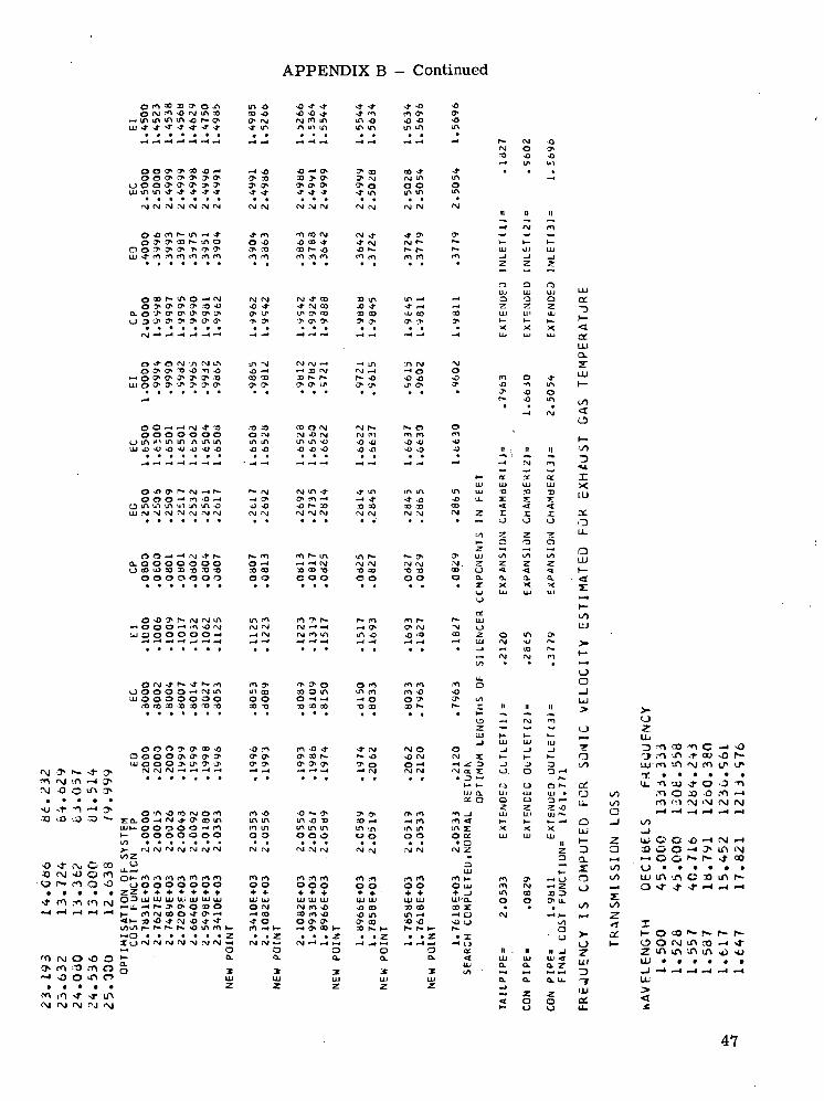
APPENDIX B - Continued
O m 00 33 O* O ,A LA O O >* -fr -fr -^ -t -OO M m «o (NJ IA co (X> *o >o<o^ •$• m m O
"— 10 to IA tA o p» o* (7^ f\i r\j m IA IA -o <o <oLLJsSf^* 1 ' ' ^ ' ^ -^ '^ «^ lA -.A >A lA LA LA IA lA
•if •*••"*•**• >^ <f •T'4''*' •& IA lAlA
rg(NjfM,-Njrst,->j tNj MfM ojr \ j f \ j rsioj ojrg
Q^ t * i r~ lA>^ ' ^ ^f*> 'OCQfy (N^ i^CT*O ^ c r o o r - t A O o^o 0^0^ ^rvj (\ir-
O O ^ O ^ ' ^ ^ T * 1 ^ O*CO c o r ^ x O •O'1^ ^"l**u j j - m m m i O f n r n mm m , r t m mpn mm
OCOr^ - lAO-^^ l f\J(M fNJ'J'CD -^OtA IA^^
O ^ O f M ' ^ f ^ l ^ tA"\J fM f\J —t -<LA '-AfvJO O x C T * ' j O < O m O sO^H *^30f\ l fvjr^ •—* O
OO^' - ' fN i^ '2> --OM coors j rvjr^ r*oO O O O O O O O^ rg-Ofs j (Nrn mm
o o o - ^ m - o ^ —<CT* o*m-^ ~* ~t -4~ *QQ l A t A l A U ^ i A I A - O O%O sO^-30 :OCO 3OCOUJ?NJ^Jo jM f \ | f \ j f \ j f\J f\| f^'NJ'NJ f \ j f^ rsjr\j
Q . O O O O O O O O-^ -H^rM rjrxj rgfsj
o o o o o o o oo coo oo oo
OsOj»r * (Mr \ j iA tAm m^r*- r«»m mr-
O r N j ^ ^ ^ r ^ m m^ ^^o om mmO O O O O - ^ ^ I A uico cooiA iAm m-oU J O O O O O O O OO O-H^ r^o O'^
. • f l r ocO ' jOB fTO^ X"O -.ocooo "Oco ao f~
(\J (\| 1N| —4 .-H —4 H —« H ^H -H «-» —I r\| PtjrM
e\J inO O
-u10
o o o o o -^ mO O O O O O O
m •oin inen ino o
-O N- CJ>m -a -oin in in000
c M C M e M C M C M C M C M
-4" c\i<\J -O!•- rl
O CO
. . i m moooooooo
ZZ + + 4- + * * +
<M SiS!
<>- 30 't/)i/i r- i
> o o co Oo^o-HCM •o -t •*•
CM CM
en mo o+ +UJ UJO N-• CO-t oen -* fc
CM fM CM
m en eno o o+ + +UJ UJ UJCM en •aco en -oo a- y*-4 0> CO I
CO ^in !n0 O
UJ UJO CO>o tnO co
fM Oro I'Oo oii -rCM oj
-O Orei O
oo.
oa.
UJz
oa.
-i mIA IAO O
cn enO O+ +UJ UJ33 COin -i•a -o
-*•ino
CMO•a
nCM
Q7L
Ma-o
a.x
en•o
o en• a
O UJ+ _)UJ-0.CO I-I O~o or~. I
— 13CC<UJ
az
en01ino
COO
OU
oHiO
oin
•z r r x— o o o
H- o a
a.x
<tex.LUQ.
XX[U
ata
aUJ
Oo
o -t/*-
o r-
ii n it _jLL) U-l LL* ^o- ex o, Z
1/3 -M N^ •— »4QL CL O. U.
I
ILi
Orj
c -< oOD sfl r—
o
o a.
-5 a-<Z i)33 3 ^<7» U- .
I/)k^a
z.a
m '.o <r O -O >,-n o oo -o ,-n •-«m to (\j <\i CM IM
uj o a -oS3 O O -<•— O O I*-
IT> IN-fr °0
O
a/
TFUJDt
lu ir\ m o 33o >t -j- -*••-<
T»- o co *• r~(J> O (XJ lA COz m in ••<> u\UJ • t • •
01
47
APPENDIX B - Continued
O* f vO U^ <T ^1" lf> AJ ! ^ — ' . -O '?» •">! -O O t" O r<1 C3 -O tr u\ 'H 3} -J- — < -D ^) .•O rH ^ ^ £1 u^ -T rT| r\J -\J r-< -Jo •*• <M o n '-u -4- NI o n -JJ i \ '"^ •"< J> o -o IA m —< o o r- m -i- ci 1-1 o o> ^~ >o ^ >r AJ >-i o J* x> ^ -o .n j- ro
r\j rj rsj rsl
48

APPENDIX B - Continued
o -f> O <** — * o ^< (*• .-"i ojr-O'<J^^~r 'J ' rr i ' " f>iNj. \ j !N j ( \ l > j (NJC \ |oO(M^
49
APPENDIX B - Continued
-o ft tr\ r*i >o in a> T3 <\i —< u> -f1 i>- r\ -o
50

APPENDIX B - Concluded
' M a r r » ' M - r > — < cr>LT\ CO 'M -O O IJ^ 3»
33 o o •& -o
51

REFERENCES
1. Anon.: Noise Control Act of 1972. Public Law 92-574, Oct. 1972.
2. Tobias, Jery V.: Noise in Light Twin-Engine Aircraft. Sound & Vib., vol. 3, Sept.1969, pp. 16-19.
3. Alfredson, R. J.: The Design and Optimization of Exhaust Silencers. Ph. D. Thesis,Inst. Sound & Vib. Res., Univ. of Southampton, July 1970.
4. Alfredson, R. J.; and Davies, P. O. A. L.: The Radiation of Sound From an EngineExhaust. J. Sound & Vib., vol. 13, no. 4, Dec. 1970, pp. 389-408.
5. Alfredson, R. J.; and Davies, P. O. A. L.: Performance of Exhaust Silencer Com-ponents. J. Sound & Vib., vol. 15, no. 2, Mar. 22, 1971, pp. 175-196.
6. Davis, Don D.; Stokes, George M.; Moore, Dewey; and Stevens, George L., Jr.:Theoretical and Experimental Investigation of Mufflers With Comments on Engine-Exhaust Muffler Design. NACA Rep. 1192, 1954. (Supersedes NACA TN's 2893and 2943.)
7. Stewart, George W.; and Lindsay, Robert Bruce: Acoustics. D. Van Nostrand Co.,Inc., 1930.
8. Strecker, F.; and Feldtkeller, R.: Grundlagen der Theorie des allgemeinen Vierpols.Elek. Nach. Tech., vol. 6, no. 3, Mar. 1929, pp. 93-112.
9. Pipes, Louis A.; and Harvill, Laurence R.: Applied Mathematics for Engineers andPhysicists. Third ed., McGraw-Hill Book Co., Inc., c.1970.
10. Igarashi, Juichi; and Toyama, Masasuke: Fundamentals of Acoustical Silencers.I - Theory and Experiment of Acoustic Low-Pass Filters. Rep. No. 339, Aeronaut.Res. Inst., Univ. of Tokyo, Dec. 1958.
11. Miwa, Toshisuke; and Igarashi, Juichi: Fundamentals of Acoustical Silencers.- II — Determination of Four Terminal Constants of Acoustical Elements. Rep.
No. 344, Aeronaut. Res. Inst., Univ. of Tokyo, May 1959.
12. Igarashi, Juichi; and Arai, Masaaki: Fundamentals of Acoustical Silencers.in — Attenuation Characteristics Studied by an Electric Simulator. Rep. No. 351,Aeronaut. Res. Inst., Univ. of Tokyo, Feb. 1960.
13. Levine, Harold; and Schwinger, Julian: On the Radiation of Sound From an UnflangedCircular Pipe. Phys. Rev., vol. 73, no. 4, Feb. 15, 1948, pp. 383-406.
14. Sacks, M. P.; and Allen, D. L.: Effects of High-Intensity Sound on Muffler ElementPerformance. J. Acoust. Soc. Amer., vol. 52, no. 3, pt. 1, Sept. 1972, pp. 725-731.
52
15. Mungur, P.; and Gladwell, G. M. L.: Acoustic Wave Propagation in a Sheared FluidContained in a Duct. J. Sound & Vib., vol. 9, no. 1, Jan. 1969, pp. 28-48.
16. Fujimoto, Shigeo: Experiment on Exhaust Muffler by Pulsating Flow. NASATT F-14,295, 1972.
53
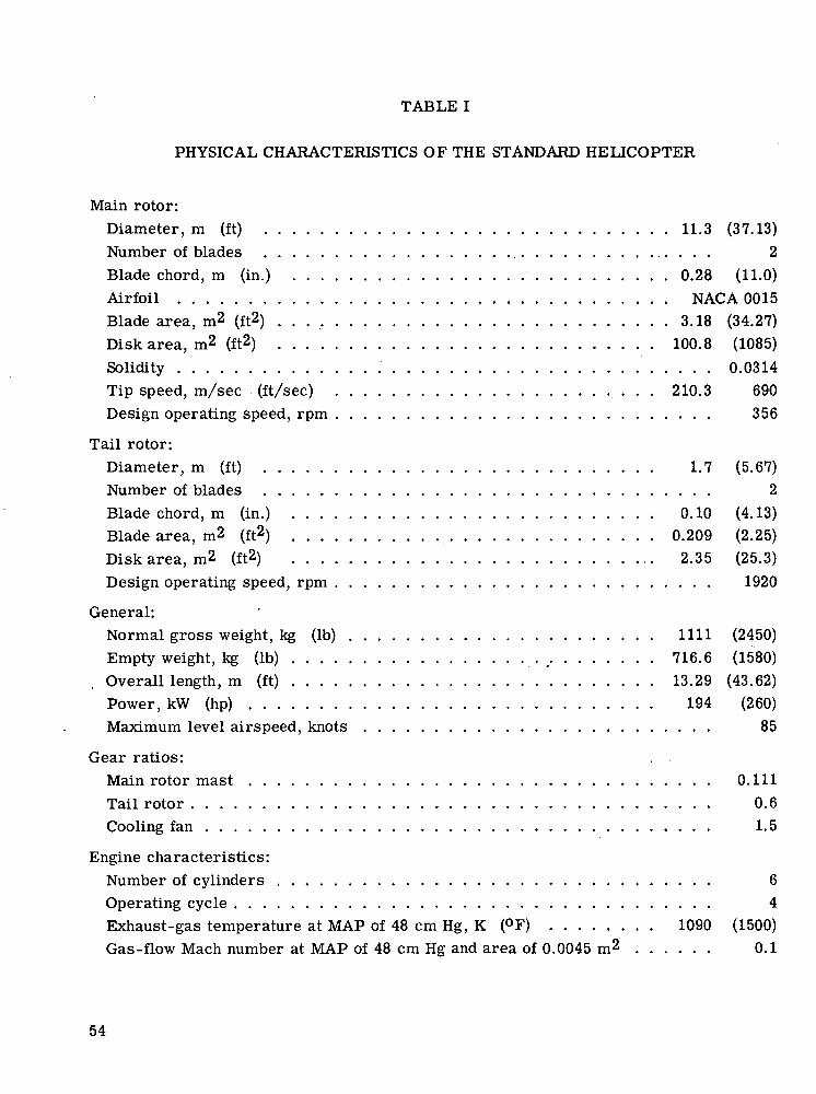
TABLE I
PHYSICAL CHARACTERISTICS OF THE STANDARD HELICOPTER
Main rotor:Diameter, m (ft) 11.3 (37.13)Number of blades 2Blade chord, m (in.) 0.28 (11.0)Airfoil NACA 0015Blade area, m2 (ft2) 3.18 (34.27)Disk area, m2 (ft2) 100.8 (1085)Solidity 0.0314Tip speed, m/sec (ft/sec) 210.3 690Design operating speed, rpm 356
Tail rotor:Diameter, m (ft) 1.7 (5.67)Number of blades 2Blade chord, m (in.) 0.10 (4.13)Blade area, m2 (ft2) 0.209 (2.25)Disk area, m2 (ft2) 2.35 (25.3)Design operating speed, rpm 1920
General:Normal gross weight, kg (Ib) 1111 (2450)Empty weight, kg (Ib) 716.6 (1580)Overall length, m (ft) 13.29 (43.62)Power, kW (hp) 194 (260)Maximum level airspeed, knots 85
Gear ratios:Main rotor mast 0.111Tail rotor 0.6Cooling fan 1.5
Engine characteristics:Number of cylinders 6Operating cycle 4Exhaust-gas temperature at MAP of 48 cm Hg, K (°F) 1090 (1500)Gas-flow Mach number at MAP of 48 cm Hg and area of 0.0045 m2 0.1
54

TABLE II.- ESTIMATED INSERTION LOSS OF MUFFLER OBTAINED FROM
MEASURED SOUND PRESSURE LEVELS OF STANDARD AND
MODIFIED EXHAUST SYSTEM
T^no*i np— Via nlc
firing-frequencyharmonic
1234567
8
Sound
Standardexhaustsystem
94.583.088.577.066.672.57fi 9
70 0
pressure level,
Y- connectoronly
819465745460
3B, for -
Y-connectorand muffler
69.569.556.564.268.069.5fiQ S
R4 2
"F.^Hmatpd
insertion lossof muffler, dB
11.524.58.59.8
-14-9.5
55
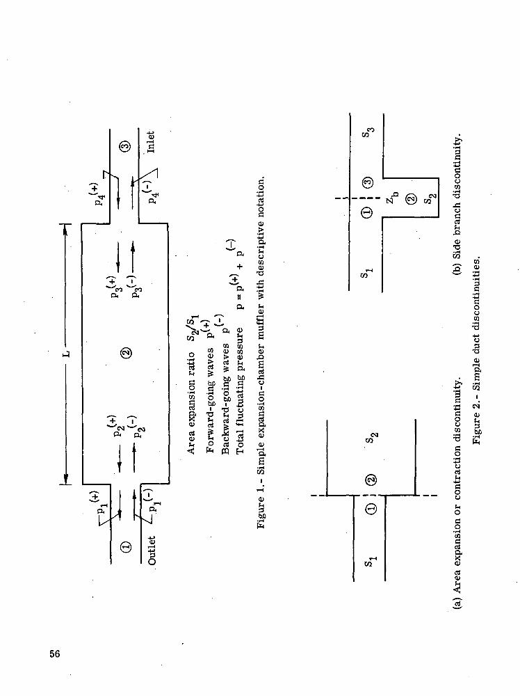
r+
^MJ1
0,
(§)
^s
1 '
1
isi— t
, HH
/\T"-a
T T^^s ^—
CO COa a
©
^N^NP< o<
I trHaI/J t6)
j;. . '~"es<
+^-^
aneu
>— i ^r^w -o- J,
>^alrO rnUJ uj
2 8 > 2tl S; ™ "g g ^ a? bD bD§ a* .a 5
s ? &!g be i S1 ^ "S Ss J3 g aS £ 1 3^ o d o< * CQ H
*^^i-H
O,
xj
•ss
do
T3rt
^_>
§CD
-4->O.'CuCOCD
T3X!-M•i-(5f-icuas?-(0),caci
exp
ansi
on- c
- S
imple
i-I(U
3faO
S
COas
N
ra
OT
<M
g
^3COuCO3urt
0)
CQ0)Z!'3
ouco=3-4-*O
•s(UI—<I
0)
•3a&0uco=3ao13urtfn43
O
i*o
o•iHCO
rt«airt(U
I
eg<b,3S
e
56
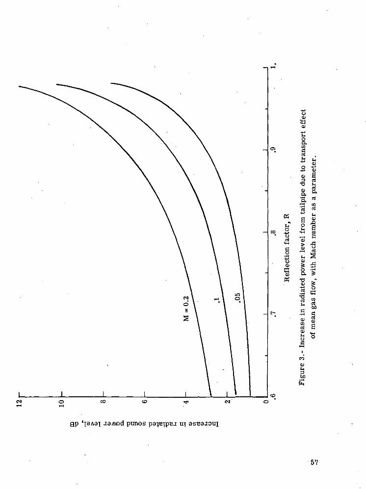
CO
K
rt«4H
§• i-H
-8O>
K
o0)
OJ
OaCO
0) S3 rt
a
"S
a><»rt
CO
a>^H
be
afi 0)I fr §
3si
evi oo CD
gp aaAvod punos ui as"B8JOui
57

oo
esi
1CO
§Q.
__ d
d
Ii-H
fe
3"
e
O•rt
5
O
1ia
VI0)^3
1OOw
rt
oM
ad
co
• iH-MOd
Ood0)!Hd
Ii-H
e
o
"deHI
•8W
S vll
.2 o5 a," a *^ J SoT5 .rt•I fli pr.
o ao a-d -1
CD
^-(->
1 ?H U
1 s §I O X!
58

f
-S&fcov .5 v§ -M •>-<O -*-1
?IlJts81\jj •*-* oCO H CQ
g-Sso
>•
-1_>(U
"3HH r•s
C CO3 tuJH &•" 0,
3 22 3
^S
/
M
S
/CL,cto
1H
r- 1
s
'
a °• 73
J S-4-*
O>
• i-f
73<U
73
"- — *>i -1 ^
cd I «' £ 0 J3
^ M -4-1n ?It Iss^ajX5art(— <
^^, «1 1
rt§ 1p^3 wJ< 0 C« rt rt•> ^ aE-y x,2g wpL( O 1r * ** 1
in0)t-,3bD
sO)
f-H
1
59

omCD
Ooo
CJ<DCO .
CQW
•II ^
O " CO
S c^o11 ^JO CO iJ
a0'e II
om
oo
oinI co
ooCO
CM
Oo
N
o0)I
Oin
oo
in OCO
inCM
Oesi
in ini
oin
I
£wCQO
I—I
co
.f-tCQCQ
• r-HaCO
oCQ
'Crt
oO
CO
O)
bD
gp 'ssoj UOISSIUISITBJJ,
60

o•"tfco
ocoin
oco
oo
05
o•esi
oco
oco
o
<u
foo
l» <X)o ~~^" sc °°.2 -CO <tHw oa sQ> tji)o) '53w x:
• rHO FHC Q), >
o> a rt^ ofe il
S &3 O
- S8 £tQ O
fliMoN
-c ^c o
I
o
OO
OCO
OCD
gp '\dAd-[ aansssjd punos
61
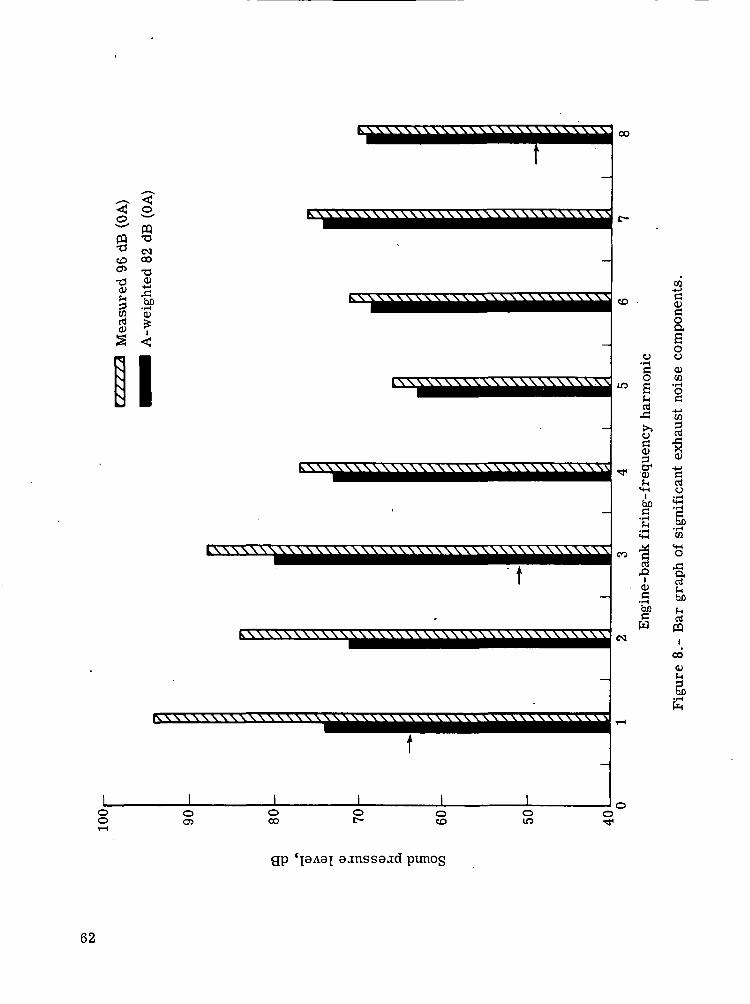
CQ -o-S <M<£> CO
°» 73
N
I LXXXXX \\X\\\ \\\\\\\\\\\\1 lf}
k\\ \\X\\ \\X\\\\\\\\\\ XX \\X\\\\\\\
KXXXXXXXXXXXXXXXXXXXXXXXXXXXXXXXXXXXXXXX
gp cpAa^ aanssajd punog
62

a3a•a
•8 Sa -sCQ O)
U P
oo
cort
•aoo
a
§ tuO **»?"\ ^
o
o
<M
•aaoO
OJ
Oin o
COoCO
gp 'ssoj uoTSSTuistreax
be
63

O)ortaw
0)'CO
ou
co
01JO.
I01
SP-wCOI
O)
«*-!o
o
IoI—I
CU
bo
E
64
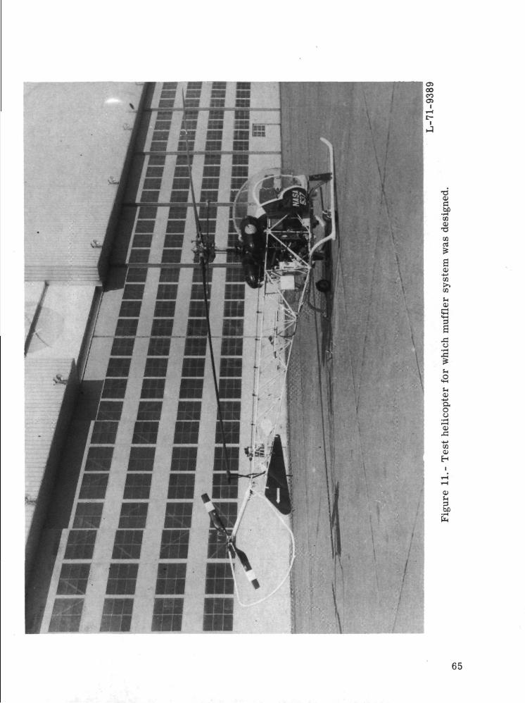
9
bC• rHCO
•s
s0)
enM
Ia
1Ma
u3J8tsuH
65

66
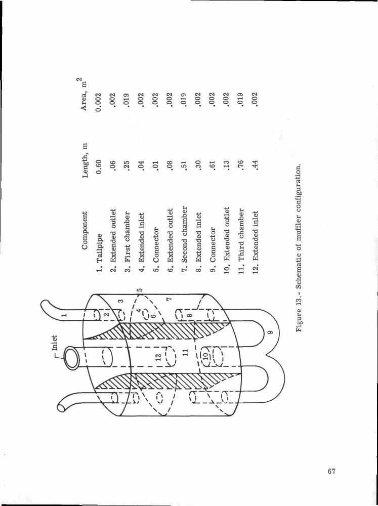
0) O Oo o
» - i Oo o
Oo
O i - H Oo o o
Oo
O » - lo o
Oo
._:•J
co.rH-t-«
rt
Tai
lpip
e
ende
d
E
co
ende
d
IT5
Con
nect
or
ende
d
in to
<U ^_,
"I •§cs -F—<
•s ?•o -oc cO 0)O -K03 ?sw w
ecto
rC
o
CO 05
1•o0)
T3
<U•sw
rt
o
H
T3QJ"S0)
/X co /\ - ^X
rrr^Vx l^ \ ^-^-TT\MI«V)/ 'j«\ VJL« ,AJ_N
Oo!HOJ
O
o
"SScu
eni
CO
67

o
"rt-4-»
cc
o—O>
o
OJ
68
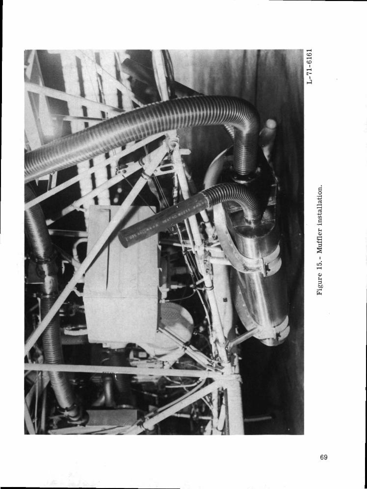
o•i-H-4->
cd
to
!HO>
01^
69
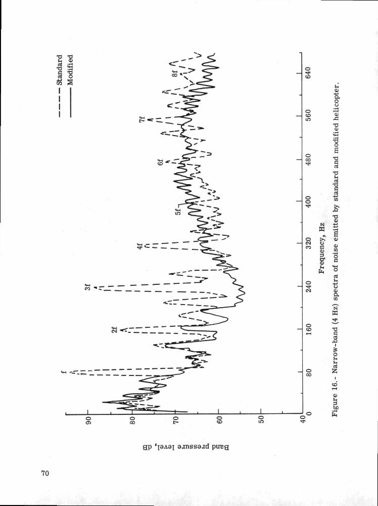
73 T3t-i 0>
•3 S9 "8
i
o•*CO
oCO10
oCO
oo
o<MCO
oTfCM
oCD
IS]
O
CJ
Oi—a8sO)
osIrt
T3U
9-t->cc
cvw
.(H
O
rtt-i
-t->Oa>an
S3^
o(H^rt
CD
01h
ho
oCD
OCO
Oc-
oCO
gp aanssaad pireg
70
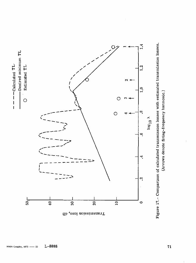
H
a3.9a
-C0)
730)
"3 £ a"3 J> $u Q wI
! oi
co
/<o
CS]
o<n
CO01coco
o•iHCOCO•IHaCO
rt
O)-4-Ja
I 7-4-> -r-lCO C0) O
^ a
CO
S II&CD!H
COco be
w .S *"re ni^ -S
^
CO3 to
oco
ao
0)(H
gp 'sso\ UOTSSIUISUBJX
NASA-Langley, 1973 . 23 L-8888 71

NATIONAL AERONAUTICS AND SPACE ADMINISTRATION
WASHINGTON, D-C. 2O546
OFFICIAL BUSINESS
PENALTY FOR PRIVATE USE S3OO SPECIAL FOURTH-CLASS RATEBOOK
POSTAGE AND FEES PAIDNATIONAL AERONAUTICS AND
SPACE ADMINISTRATION451
POSTMASTER : If Undeliverable (Section 158Postal Manual) Do Not Return
'The aeronautical and space activities of the United States shall beconducted so as to contribute . . . to the expansion of human knowl-edge of phenomena in the atmosphere and space. The Administrationshall provide for the widest practicable and appropriate disseminationof information concerning its activities and the results thereof."
—NATIONAL AERONAUTICS AND SPACE ACT OF 1958
NASA SCIENTIFIC AND TECHNICAL PUBLICATIONSTECHNICAL REPORTS: Scientific andtechnical information considered important,complete, and 3- lasting contribution to existingknowledge.
TECHNICAL NOTES: Information less broadin scope but nevertheless of importance as acontribution to existing knowledge.
TECHNICAL MEMORANDUMS:Information receiving limited distributionbecause of preliminary data, security classifica-tion, or other reasons. Also includes conferenceproceedings with either limited or unlimiteddistribution.
CONTRACTOR REPORTS: Scientific andtechnical information generated under a NASAcontract or grant and considered an importantcontribution to existing knowledge.
TECHNICAL TRANSLATIONS: Informationpublished in a foreign language consideredto merit NASA distribution in English.
SPECIAL PUBLICATIONS: Informationderived from or of value to NASA activities.Publications include final reports of majorprojects, monographs, data compilations,handbooks, sourcebooks, and specialbibliographies.
TECHNOLOGY UTILIZATIONPUBLICATIONS: Information on technologyused by NASA that may be of particularinterest in commercial and other non-aerospaceapplications. Publications include Tech Briefs,Technology Utilization Reports andTechnology Surveys.
Details on the availability of these publications may be. obtained from:
SCIENTIFIC AND TECHNICAL INFORMATION OFFICE
NATIONAL A E R O N A U T I C S AND S P A C E ADMINISTRATION
Washington, D.C. 20546