An Improved CPW-Fed Printed UWB Antenna With...
12
Journal of Communication Engineering, Vol. 5, No. 1, January–June 2016 38 Manuscript received 16-Dec.-2015 and revised 1-March-2016 P- ISSN: 2322-4088 Accepted on 15-April-2016 E- ISSN: 2322-3936 Abstract— A newly designed printed slot antenna is presented that incorporates variable two band-notched functions for ultra- wideband (UWB) applications. The two band notches of this coplanar waveguide (CPW) fed antenna are achieved by an M- shaped slot (MSS) embedded in the radiating element and a C- shaped strip (CSS) close to ground plane, therefore two very narrow rejected properties in the wireless local area network (WLAN) band (5.15-5.825 GHz) and worldwide interoperability for microwave access (WiMAX) operation in the (3.3-3.7GHz) are obtained. The rectangular aperture is etched in the square ground plane. It has a determinative role in antenna’s impedance bandwidth (IBW) enhancement; moreover, by adjusting carefully it leads to wide IBW. Based on simulated results it covers the frequency range 2.4–12.9 GHz with VSWR ≤ 2, which corresponds to a fractional bandwidth of 137% excluding the rejected bands. Numerical and measured results are presented to understand its behavior. The volume of the proposed antenna is 25 × 25 × 0.8 mm 3 . Index Terms— Slot antenna; ultra-wideband antenna; WLAN; WiMAX; band- notched function I. INTRODUCTION In recent years, the development of ultra-wideband (UWB) antennas facilitating high data transmission rates and low power consumption, and simple hardware configuration in communication application has received attention [1–17]. The Federal communication commission (FCC) allocated the frequency band 3.1– 10.6 GHz for commercial UWB systems in 2002 [2,13,14]. Despite the approval of the FCC for the UWB to operate 3.1– 10.6 GHz, it may be necessary to avoid potential interferences with other existing communication systems, such as Worldwide Interoperability for the Microwave Access (WiMAX) operating at 3.3–3.7 GHz; Wireless Local Area Network (WLAN) is operated at 5.15–5.825 GHz [3–11]. Therefore, UWB antenna with notched characteristics at these frequency bands is required. The conventional methods are cutting a slot (U- shaped, arc shaped, T-shaped slot) on the patch [5,9]. Inserting a slit on the patch [14], another way is An Improved CPW-Fed Printed UWB Antenna With Controllable Band-notched Functions Y. Zehforoosh and T. Sedghi Department of Electrical Engineering, Urmia Branch, Islamic Azad University, Urmia, Iran. [email protected], [email protected] Corresponding author: Y. Zehforoosh
Transcript of An Improved CPW-Fed Printed UWB Antenna With...

Journal of Communication Engineering, Vol. 5, No. 1, January–June 2016 38
Manuscript received 16-Dec.-2015 and revised 1-March-2016 P- ISSN: 2322-4088 Accepted on 15-April-2016 E- ISSN: 2322-3936
Abstract— A newly designed printed slot antenna is presented that incorporates variable two band-notched functions for ultra-wideband (UWB) applications. The two band notches of this coplanar waveguide (CPW) fed antenna are achieved by an M-shaped slot (MSS) embedded in the radiating element and a C-shaped strip (CSS) close to ground plane, therefore two very narrow rejected properties in the wireless local area network (WLAN) band (5.15-5.825 GHz) and worldwide interoperability for microwave access (WiMAX) operation in the (3.3-3.7GHz) are obtained. The rectangular aperture is etched in the square ground plane. It has a determinative role in antenna’s impedance bandwidth (IBW) enhancement; moreover, by adjusting carefully it leads to wide IBW. Based on simulated results it covers the frequency range 2.4–12.9 GHz with VSWR ≤ 2, which corresponds to a fractional bandwidth of 137% excluding the rejected bands. Numerical and measured results are presented to understand its behavior. The volume of the proposed antenna is 25 × 25 × 0.8 mm3.
Index Terms— Slot antenna; ultra-wideband antenna; WLAN; WiMAX; band-notched function
I. INTRODUCTION
In recent years, the development of ultra-wideband (UWB) antennas facilitating high data
transmission rates and low power consumption, and simple hardware configuration in communication
application has received attention [1–17]. The Federal communication commission (FCC) allocated
the frequency band 3.1– 10.6 GHz for commercial UWB systems in 2002 [2,13,14].
Despite the approval of the FCC for the UWB to operate 3.1– 10.6 GHz, it may be necessary to
avoid potential interferences with other existing communication systems, such as Worldwide
Interoperability for the Microwave Access (WiMAX) operating at 3.3–3.7 GHz; Wireless Local Area
Network (WLAN) is operated at 5.15–5.825 GHz [3–11]. Therefore, UWB antenna with notched
characteristics at these frequency bands is required. The conventional methods are cutting a slot (U-
shaped, arc shaped, T-shaped slot) on the patch [5,9]. Inserting a slit on the patch [14], another way is
An Improved CPW-Fed Printed UWB Antenna With Controllable Band-notched Functions
Y. Zehforoosh and T. Sedghi Department of Electrical Engineering, Urmia Branch, Islamic Azad University, Urmia, Iran.
[email protected], [email protected] Corresponding author: Y. Zehforoosh
39 CPW-fed printed UWB antenna with controllable band-notched
Fig.1. Geometry of the proposed antenna, Lg1 = 4.8, Lg2 = 6.5, Ys = 2.5, L1 = 3.6, L2 = 3.4, L3 = 13, W1 = 0.25,
W2 = 1.25, W3 = 5, W4 = 22 and W5 = 2. (Optimized dimensions in mm).
putting parasitic elements as filters are existing to reject the electromagnetic interference (EMI).
In this letter, we describe a cpw-fed UWB antenna with dual band-notched characteristic. To achieve
the two notched frequency bands, a M-shaped slot (MSS) embedded in the radiating element and a C-
shaped strip(CSS) close to ground plane are used. Numerical and experimental results are presented to
understand its behavior. The simulated and measured results show that the proposed antenna has a
wide impedance bandwidth, omnidirectional patterns, and dual band-notched characteristics.
II. ANTENNA DESIGN AND SIMULATION
Fig. 1 shows the configuration of the proposed UWB monopole antenna which consists of 50Ω
CPW transmission line and a strip width of 3.1mm with gap width of 0.3mm. An antenna structure
consists of a semi-circle exciting stub with MSS and an inverted CSS near the top edge of the
aperture. Two main factors that have been aimed in the proposed antenna design are:
I) achieving wide impedance bandwidth
II) filtering the WLAN& WiMAX bands.
For the first purpose, based on electromagnet coupling theory, the rectangular aperture inside the
ground plane is playing an important role in the broadband characteristics of this antenna, because it
Journal of Communication Engineering, Vol. 5, No. 1, January–June 2016 40
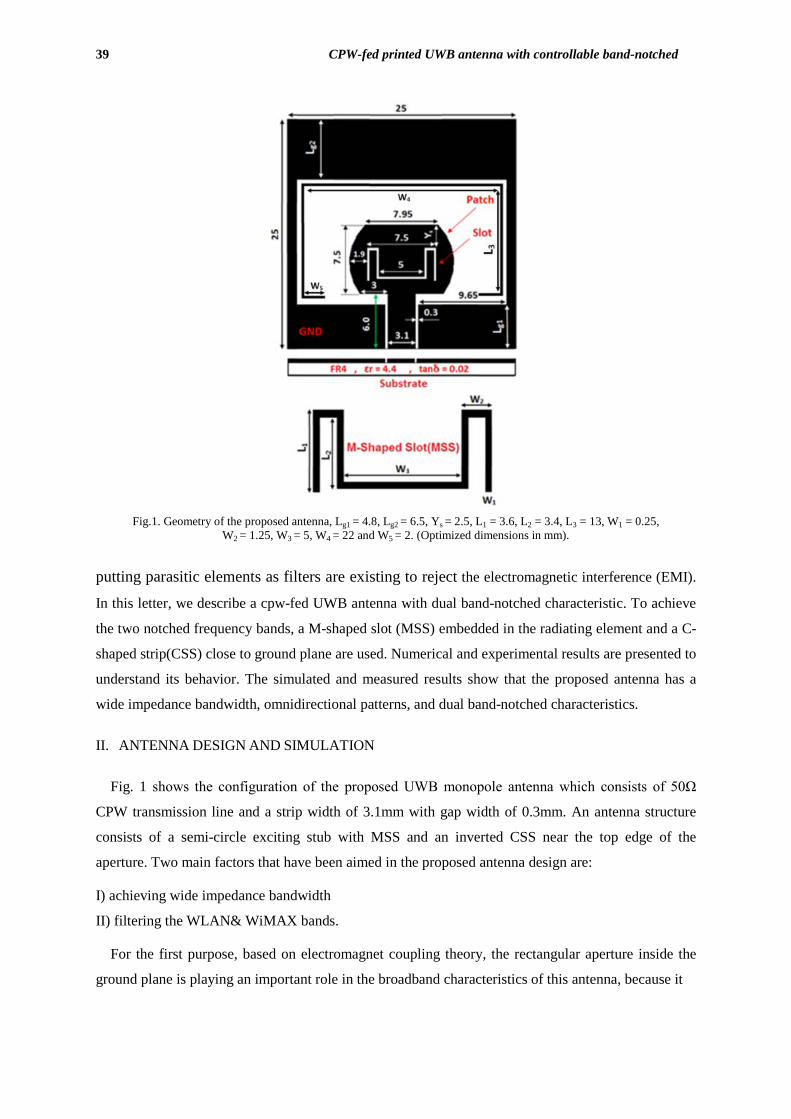
Fig. 2. Design procedure of inverted C-shaped strip in the proposed antenna
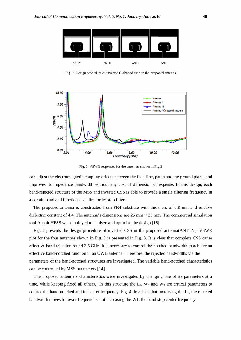
Fig. 3. VSWR responses for the antennas shown in Fig.2
can adjust the electromagnetic coupling effects between the feed-line, patch and the ground plane, and
improves its impedance bandwidth without any cost of dimension or expense. In this design, each
band-rejected structure of the MSS and inverted CSS is able to provide a single filtering frequency in
a certain band and functions as a first order stop filter.
The proposed antenna is constructed from FR4 substrate with thickness of 0.8 mm and relative
dielectric constant of 4.4. The antenna’s dimensions are 25 mm × 25 mm. The commercial simulation
tool Ansoft HFSS was employed to analyze and optimize the design [18].
Fig. 2 presents the design procedure of inverted CSS in the proposed antenna(ANT IV). VSWR
plot for the four antennas shown in Fig. 2 is presented in Fig. 3. It is clear that complete CSS cause
effective band rejection round 3.5 GHz. It is necessary to control the notched bandwidth to achieve an
effective band-notched function in an UWB antenna. Therefore, the rejected bandwidths via the
parameters of the band-notched structures are investigated. The variable band-notched characteristics
can be controlled by MSS parameters [14].
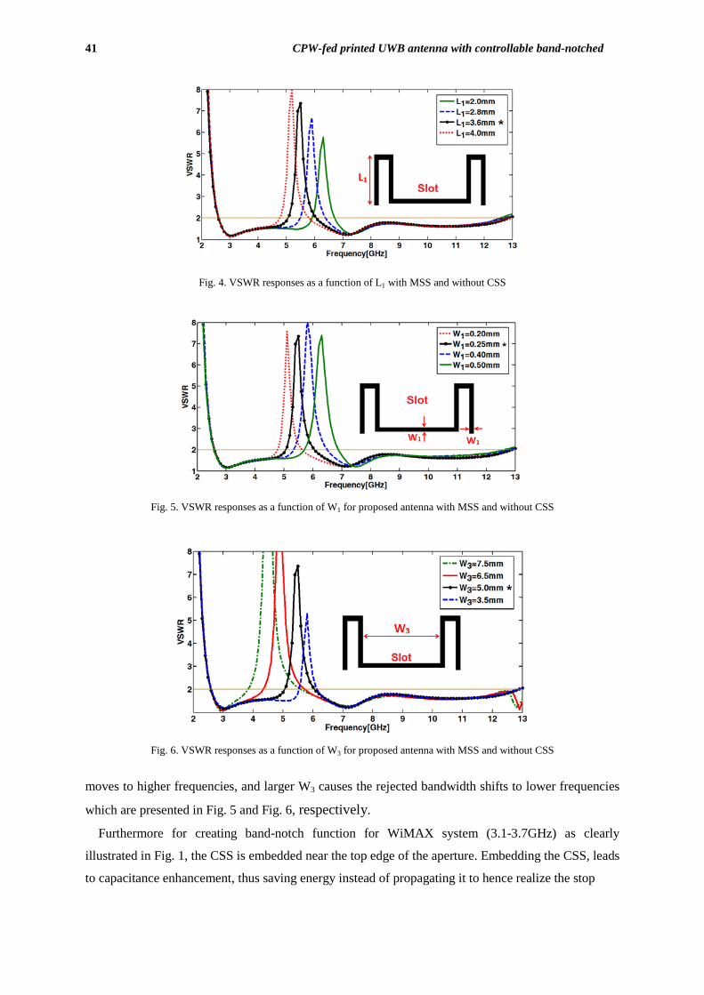
The proposed antenna’s characteristics were investigated by changing one of its parameters at a
time, while keeping fixed all others. In this structure the L1, W1 and W3 are critical parameters to
control the band-notched and its center frequency. Fig. 4 describes that increasing the L1, the rejected
bandwidth moves to lower frequencies but increasing the W1, the band stop center frequency
41 CPW-fed printed UWB antenna with controllable band-notched
Fig. 4. VSWR responses as a function of L1 with MSS and without CSS
Fig. 5. VSWR responses as a function of W1 for proposed antenna with MSS and without CSS
Fig. 6. VSWR responses as a function of W3 for proposed antenna with MSS and without CSS
moves to higher frequencies, and larger W3 causes the rejected bandwidth shifts to lower frequencies
which are presented in Fig. 5 and Fig. 6, respectively.
Furthermore for creating band-notch function for WiMAX system (3.1-3.7GHz) as clearly
illustrated in Fig. 1, the CSS is embedded near the top edge of the aperture. Embedding the CSS, leads
to capacitance enhancement, thus saving energy instead of propagating it to hence realize the stop
Journal of Communication Engineering, Vol. 5, No. 1, January–June 2016 42
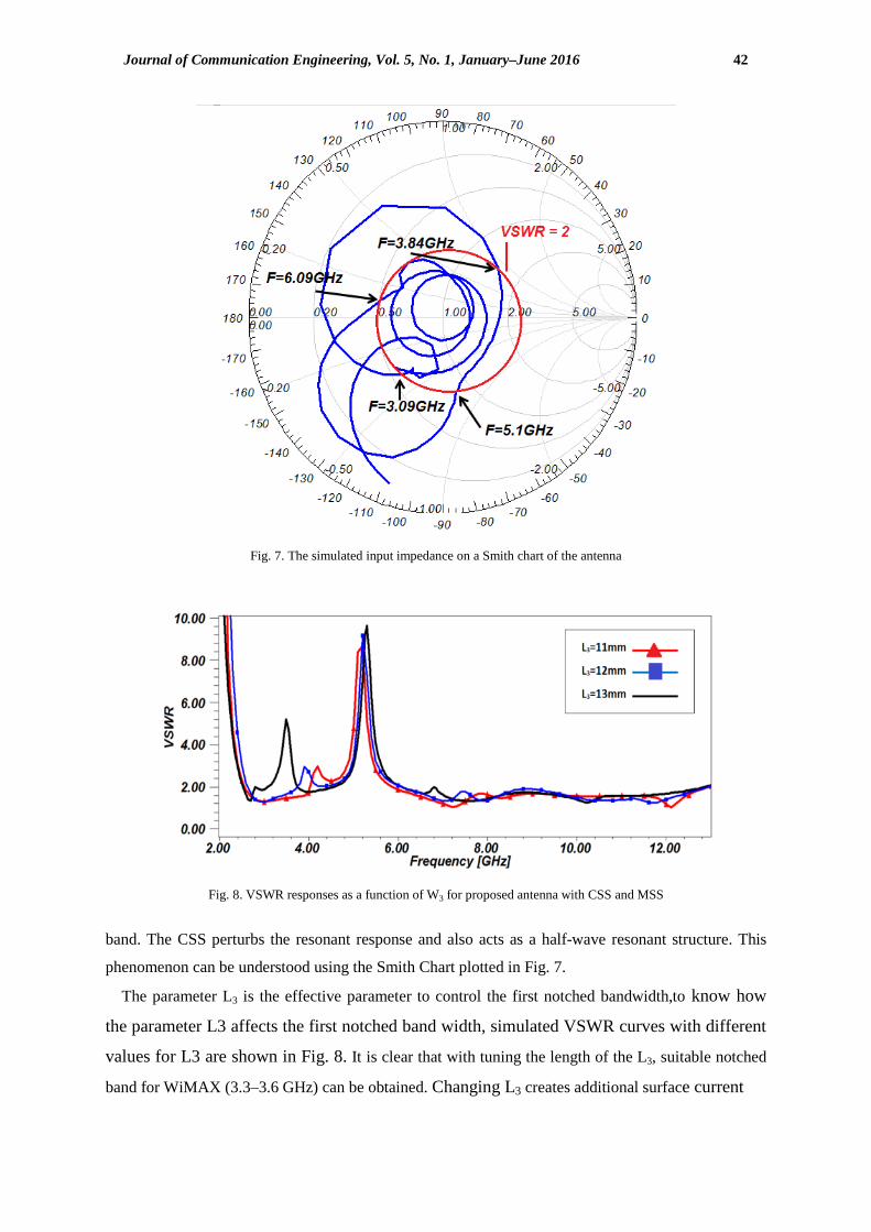
Fig. 7. The simulated input impedance on a Smith chart of the antenna
Fig. 8. VSWR responses as a function of W3 for proposed antenna with CSS and MSS
band. The CSS perturbs the resonant response and also acts as a half-wave resonant structure. This
phenomenon can be understood using the Smith Chart plotted in Fig. 7.
The parameter L3 is the effective parameter to control the first notched bandwidth,to know how
the parameter L3 affects the first notched band width, simulated VSWR curves with different
values for L3 are shown in Fig. 8. It is clear that with tuning the length of the L3, suitable notched
band for WiMAX (3.3–3.6 GHz) can be obtained. Changing L3 creates additional surface current
43 CPW-fed printed UWB antenna with controllable band-notched
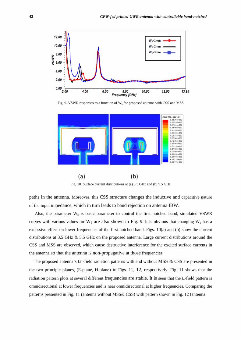
Fig. 9. VSWR responses as a function of W5 for proposed antenna with CSS and MSS
Fig. 10. Surface current distributions at (a) 3.5 GHz and (b) 5.5 GHz
paths in the antenna. Moreover, this CSS structure changes the inductive and capacitive nature
of the input impedance, which in turn leads to band rejection on antenna IBW.
Also, the parameter W5 is basic parameter to control the first notched band, simulated VSWR
curves with various values for W5 are also shown in Fig. 9. It is obvious that changing W5 has a
excessive effect on lower frequencies of the first notched band. Figs. 10(a) and (b) show the current
distributions at 3.5 GHz & 5.5 GHz on the proposed antenna. Large current distributions around the
CSS and MSS are observed, which cause destructive interference for the excited surface currents in
the antenna so that the antenna is non-propagative at those frequencies.
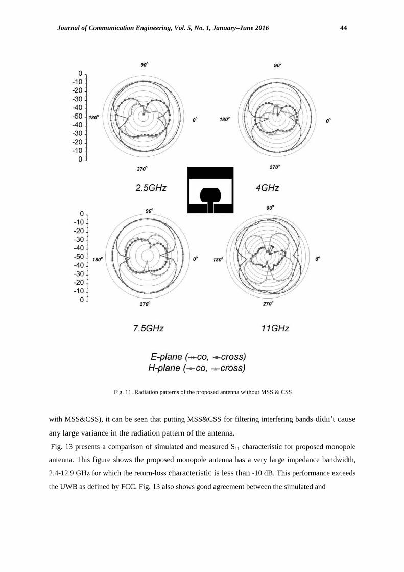
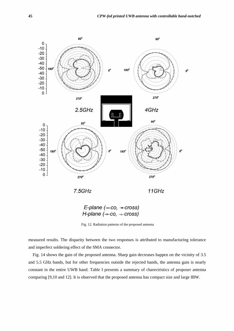
The proposed antenna’s far-field radiation patterns with and without MSS & CSS are presented in
the two principle planes, (E-plane, H-plane) in Figs. 11, 12, respectively. Fig. 11 shows that the
radiation pattern plots at several different frequencies are stable. It is seen that the E-field pattern is
omnidirectional at lower frequencies and is near omnidirectional at higher frequencies. Comparing the
patterns presented in Fig. 11 (antenna without MSS& CSS) with pattern shown in Fig. 12 (antenna
Journal of Communication Engineering, Vol. 5, No. 1, January–June 2016 44
Fig. 11. Radiation patterns of the proposed antenna without MSS & CSS
with MSS&CSS), it can be seen that putting MSS&CSS for filtering interfering bands didn’t cause
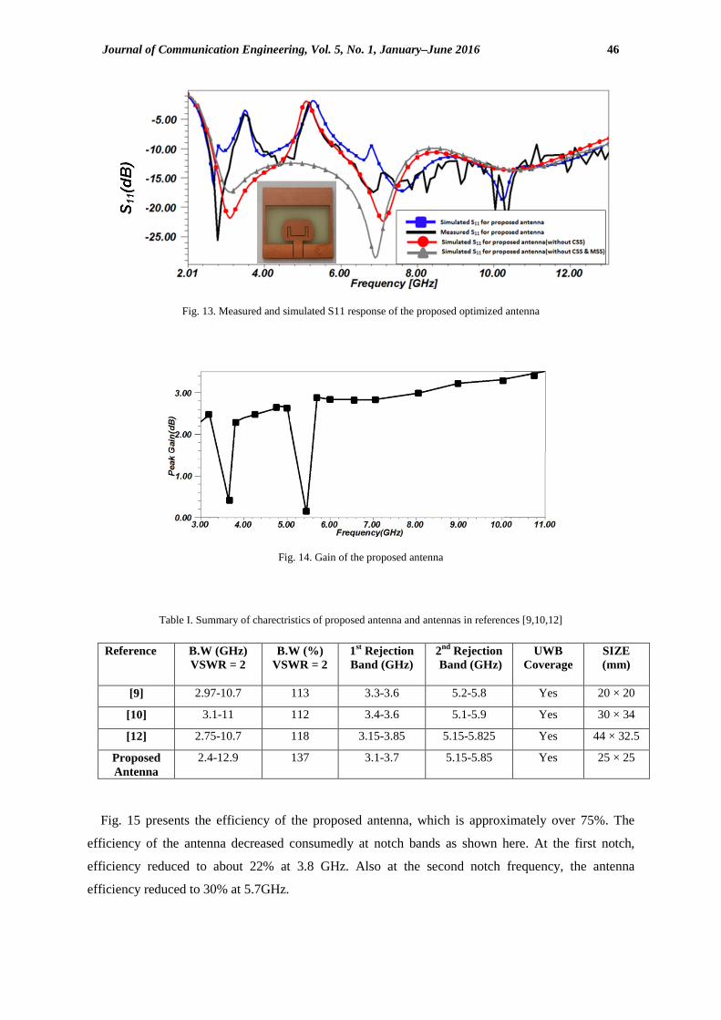
any large variance in the radiation pattern of the antenna. Fig. 13 presents a comparison of simulated and measured S11 characteristic for proposed monopole
antenna. This figure shows the proposed monopole antenna has a very large impedance bandwidth,
2.4-12.9 GHz for which the return-loss characteristic is less than -10 dB. This performance exceeds
the UWB as defined by FCC. Fig. 13 also shows good agreement between the simulated and
45 CPW-fed printed UWB antenna with controllable band-notched
Fig. 12. Radiation patterns of the proposed antenna measured results. The disparity between the two responses is attributed to manufacturing tolerance
and imperfect soldering effect of the SMA connector.
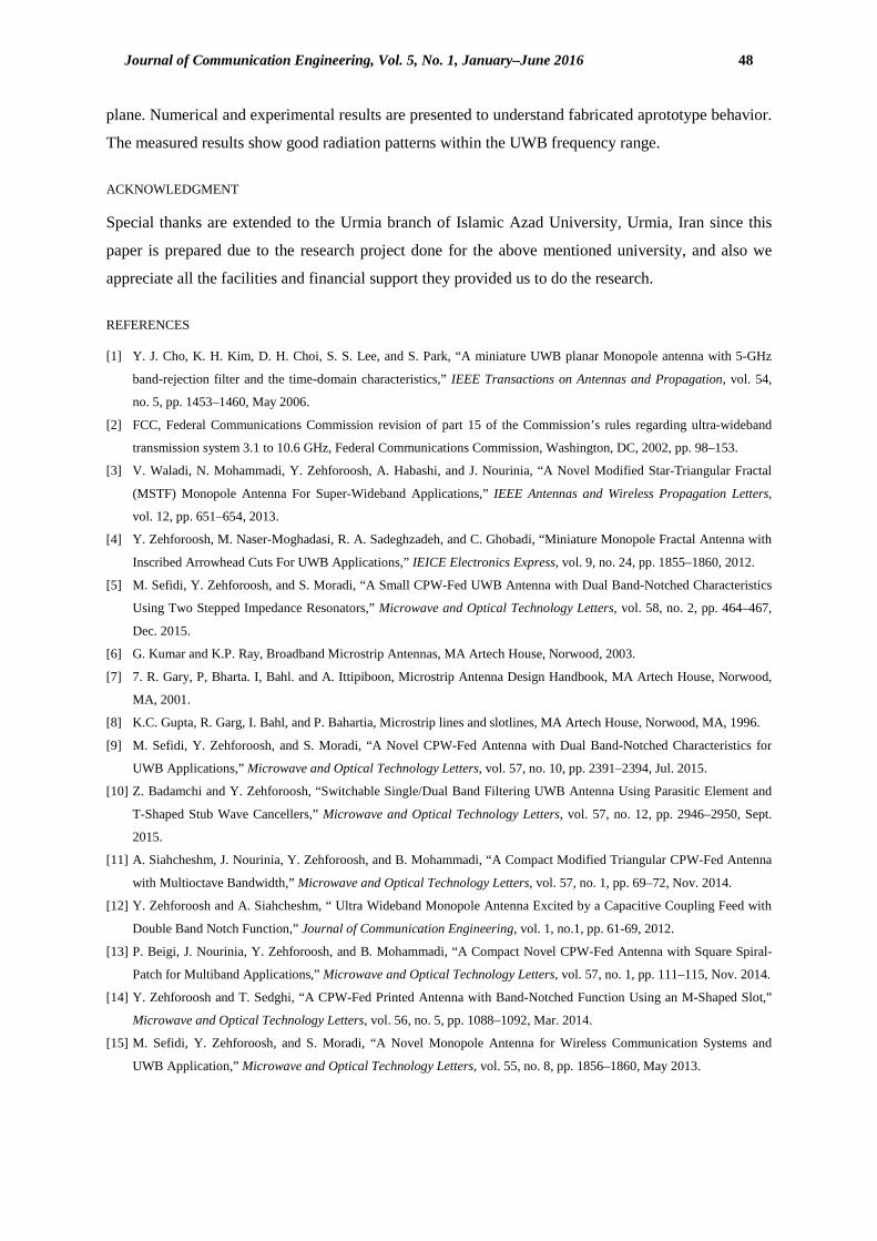
Fig. 14 shows the gain of the proposed antenna. Sharp gain decreases happen on the vicinity of 3.5
and 5.5 GHz bands, but for other frequencies outside the rejected bands, the antenna gain is nearly
constant in the entire UWB band. Table I presents a summary of charectristics of proposer antenna
comparing [9,10 and 12]. It is observed that the proposed antenna has compact size and large IBW.
Journal of Communication Engineering, Vol. 5, No. 1, January–June 2016 46
Fig. 13. Measured and simulated S11 response of the proposed optimized antenna
Fig. 14. Gain of the proposed antenna
Table I. Summary of charectristics of proposed antenna and antennas in references [9,10,12]
Reference B.W (GHz) VSWR = 2
B.W (%) VSWR = 2
1st Rejection Band (GHz)
2nd Rejection Band (GHz)
UWB Coverage
SIZE (mm)
[9] 2.97-10.7 113 3.3-3.6 5.2-5.8 Yes 20 × 20
[10] 3.1-11 112 3.4-3.6 5.1-5.9 Yes 30 × 34
[12] 2.75-10.7 118 3.15-3.85 5.15-5.825 Yes 44 × 32.5
Proposed Antenna
2.4-12.9 137 3.1-3.7 5.15-5.85 Yes 25 × 25
Fig. 15 presents the efficiency of the proposed antenna, which is approximately over 75%. The
efficiency of the antenna decreased consumedly at notch bands as shown here. At the first notch,
efficiency reduced to about 22% at 3.8 GHz. Also at the second notch frequency, the antenna
efficiency reduced to 30% at 5.7GHz.

47 CPW-fed printed UWB antenna with controllable band-notched
Fig. 15. Efficiency of the proposed antenna
Fig. 16. Group delay of the transfer system.
Reflection coefficient, gain, efficiency and radiation pattern are important parameters of UWB
antennas. Other important parameters include system transfer function and group delay. Ideally, group
delay in UWB applications should be constant over the entire bandwidth as well. To achieve the
group delay characteristic, the distance between the two antennas was 30 cm, which attain -
field position of the antenna. The group delay is about 1 ns across the frequency band except in the
notched bands shown if Fig. 16. For the rest of the frequency band, the group delay characteristic is
rather smooth, showing that the antennas have good linear transmission performances.
III. CONCLUSION
In this article, a compact planar monopole antenna is proposed that exhibits 2.4-12.9 GHz bandwidth
and easily satisfies the requirements for UWB applications. The antenna has inherent band-notch
characteristics which is necessary to solve the interfering problem between WiMAX(3.1-3.7GHz) and
WLAN(5.15-5.85GHz) with the UWB spectrum. To obtian the two stopped bands, two specific form
of an M-shaped slot (MSS) and C-shaped strip(CSS) are inserted in the radiating element and ground
Journal of Communication Engineering, Vol. 5, No. 1, January–June 2016 48
plane. Numerical and experimental results are presented to understand fabricated aprototype behavior.
The measured results show good radiation patterns within the UWB frequency range.
ACKNOWLEDGMENT
Special thanks are extended to the Urmia branch of Islamic Azad University, Urmia, Iran since this
paper is prepared due to the research project done for the above mentioned university, and also we
appreciate all the facilities and financial support they provided us to do the research.
REFERENCES
[1] Y. J. Cho, K. H. Kim, D. H. Choi, S. S. Lee, and S. Park, “A miniature UWB planar Monopole antenna with 5-GHz
band-rejection filter and the time-domain characteristics,” IEEE Transactions on Antennas and Propagation, vol. 54,
no. 5, pp. 1453–1460, May 2006.
[2] FCC, Federal Communications Commission revision of part 15 of the Commission’s rules regarding ultra-wideband
transmission system 3.1 to 10.6 GHz, Federal Communications Commission, Washington, DC, 2002, pp. 98–153.
[3] V. Waladi, N. Mohammadi, Y. Zehforoosh, A. Habashi, and J. Nourinia, “A Novel Modified Star-Triangular Fractal
(MSTF) Monopole Antenna For Super-Wideband Applications,” IEEE Antennas and Wireless Propagation Letters,
vol. 12, pp. 651–654, 2013.
[4] Y. Zehforoosh, M. Naser-Moghadasi, R. A. Sadeghzadeh, and C. Ghobadi, “Miniature Monopole Fractal Antenna with
Inscribed Arrowhead Cuts For UWB Applications,” IEICE Electronics Express, vol. 9, no. 24, pp. 1855–1860, 2012.
[5] M. Sefidi, Y. Zehforoosh, and S. Moradi, “A Small CPW-Fed UWB Antenna with Dual Band-Notched Characteristics
Using Two Stepped Impedance Resonators,” Microwave and Optical Technology Letters, vol. 58, no. 2, pp. 464–467,
Dec. 2015.
[6] G. Kumar and K.P. Ray, Broadband Microstrip Antennas, MA Artech House, Norwood, 2003.
[7] 7. R. Gary, P, Bharta. I, Bahl. and A. Ittipiboon, Microstrip Antenna Design Handbook, MA Artech House, Norwood,
MA, 2001.
[8] K.C. Gupta, R. Garg, I. Bahl, and P. Bahartia, Microstrip lines and slotlines, MA Artech House, Norwood, MA, 1996.
[9] M. Sefidi, Y. Zehforoosh, and S. Moradi, “A Novel CPW-Fed Antenna with Dual Band-Notched Characteristics for
UWB Applications,” Microwave and Optical Technology Letters, vol. 57, no. 10, pp. 2391–2394, Jul. 2015.
[10] Z. Badamchi and Y. Zehforoosh, “Switchable Single/Dual Band Filtering UWB Antenna Using Parasitic Element and
T-Shaped Stub Wave Cancellers,” Microwave and Optical Technology Letters, vol. 57, no. 12, pp. 2946–2950, Sept.
2015.
[11] A. Siahcheshm, J. Nourinia, Y. Zehforoosh, and B. Mohammadi, “A Compact Modified Triangular CPW-Fed Antenna
with Multioctave Bandwidth,” Microwave and Optical Technology Letters, vol. 57, no. 1, pp. 69–72, Nov. 2014.
[12] Y. Zehforoosh and A. Siahcheshm, “ Ultra Wideband Monopole Antenna Excited by a Capacitive Coupling Feed with
Double Band Notch Function,” Journal of Communication Engineering, vol. 1, no.1, pp. 61-69, 2012.
[13] P. Beigi, J. Nourinia, Y. Zehforoosh, and B. Mohammadi, “A Compact Novel CPW-Fed Antenna with Square Spiral-
Patch for Multiband Applications,” Microwave and Optical Technology Letters, vol. 57, no. 1, pp. 111–115, Nov. 2014.
[14] Y. Zehforoosh and T. Sedghi, “A CPW-Fed Printed Antenna with Band-Notched Function Using an M-Shaped Slot,”
Microwave and Optical Technology Letters, vol. 56, no. 5, pp. 1088–1092, Mar. 2014.
[15] M. Sefidi, Y. Zehforoosh, and S. Moradi, “A Novel Monopole Antenna for Wireless Communication Systems and
UWB Application,” Microwave and Optical Technology Letters, vol. 55, no. 8, pp. 1856–1860, May 2013.
49 CPW-fed printed UWB antenna with controllable band-notched
[16] M. Naser-Moghadasi, G. R. Dadashzadeh, M. Abdollahvand, Y. Zehforoosh, and B. S. Virdee, “Planar triangular
monopole antenna with multioctave bandwidth,” Microwave and Optical Technology Letters, vol. 53, no. 1, pp. 10–14,
Nov. 2010.
[17] C.-M. Li and L.-H. Ye, “Improved Dual Band-Notched UWB Slot Antenna with Controllable Notched Bandwidths,”
Progress In Electromagnetics Research, vol. 115, pp. 477–493, 2011.
[18] Ansoft High Frequency Structure Simulation (HFSS). Ver 10, Ansoft Corporation, Pittsburgh, PA, 2005.


![Research Article Directive Stacked Patch Antenna for UWB ...InternationalJournal of Antennas and Propagation [] W.S.T.RoweandR.B.Waterhouse, Reductionofbackward radiation for CPW fed](https://static.fdocuments.us/doc/165x107/60d5f61c7f0a5b13536c1a8f/research-article-directive-stacked-patch-antenna-for-uwb-internationaljournal.jpg)


![AN OPTIMAL DESIGN OF CPW-FED UWB APERTURE ANTENNAS … · wave resonant structures) in the antenna’s tuning stub, such as a U-shaped [27], V-shaped [3], C-shaped slots [27,28],](https://static.fdocuments.us/doc/165x107/5e6f2490d68cd01abb03376b/an-optimal-design-of-cpw-fed-uwb-aperture-antennas-wave-resonant-structures-in.jpg)