An experimental study on the seismic behavior of infilled...
33
1 An experimental study on the seismic behavior of infilled RC frames with opening Corresponding Author: Asist. Prof. Hamide TEKELİ Suleyman Demirel University Department of Civil Engineering Isparta, Turkey Tel : +(90)-(246)-2111190 Mobil Number : +(90)-(533)-7257009 Fax: +(90)-(246)-2370859 E-mail: [email protected] Co-Author: MSc Student Asım AYDIN Suleyman Demirel University Department of Civil Engineering Isparta, Turkey Fax: +(90)-(246)-2370859 Mobil Number : +(90)-(532)-3207612 E-mail: [email protected]
Transcript of An experimental study on the seismic behavior of infilled...

1
An experimental study on the seismic behavior of infilled
RC frames with opening
Corresponding Author:
Asist. Prof.
Hamide TEKELİ
Suleyman Demirel University
Department of Civil Engineering
Isparta, Turkey
Tel : +(90)-(246)-2111190
Mobil Number : +(90)-(533)-7257009
Fax: +(90)-(246)-2370859
E-mail: [email protected]
Co-Author:
MSc Student
Asım AYDIN
Suleyman Demirel University
Department of Civil Engineering
Isparta, Turkey
Fax: +(90)-(246)-2370859
Mobil Number : +(90)-(532)-3207612
E-mail: [email protected]

2
AUTHORS’ BIOGRAPHIES
Hamide Tekeli is an assistant professor in the Civil Engineering Department of Suleyman
Demirel University in Isparta, Turkey. She received her PhD from Suleyman Demirel
University in 2006. She specializes in the areas of behavior and modeling of reinforced
concrete buildings. Her research focuses on experimental and theoretical studies.
Asim Aydin is MSc student in the Civil Engineering Department of Suleyman Demirel
University in Isparta, Turkey, and he works as a civil engineer in the Kelesoglu Construction
Company in Ankara, Turkey. His research interests include modeling of reinforced concrete
structures, and repair and strengthening of earthquake-damaged structures.
3
An experimental study on the seismic behavior of infilled
RC frames with opening
Hamide Tekeli*1, Asım Aydın1a
1Department of Civil Engineering, Suleyman Demirel University, Isparta, Turkey
(Received , Revised , Accepted )
Abstract. Infill walls are generally not taken into account in structural analysis due to their complex
behavior at seismic actions. As it is known, they increase the stiffness as well as the lateral load capacity of
the system. Sometimes, infill walls may have window and door openings in their planes. In the present
study, behavior of reinforced concrete (RC) frames with infill wall which have openings is investigated
under cyclic lateral loadings. Location and size of the openings in the infill wall are selected as
investigation parameters. Test specimens are constructed and experimentally analyzed. The infill wall
changes the behavior of the frames under cyclic lateral loads significantly. Location and size openings in
the infill wall are two main parameters which affect the behavior of the infill walls as well as on that of the
frame. The test results clearly show that the contribution of the infill wall to the behavior of RC frame has
diminished significantly when the opening ratio is larger than 9%. Therefore, the effect of the opening in
the infill wall must be taken into account in the structural modeling when the opening ratio is larger than
9%.
Keywords: Infill wall; opening; reinforced concrete buildings; cyclic lateral loading; location and size of
the openings
*Corresponding Author, Asist. Prof., E-mail: [email protected]
a MSc Student, E-mail: [email protected]

4
1. Introduction
Reinforced concrete (RC) frames with masonry infill walls are widely used in structural systems in
many parts of the world. It is known that influence of infill walls on the behavior of frames, which are
subjected to earthquake loadings, is very important in some cases. If the infill walls are uniformly
distributed throughout the structure, then they usually have a beneficial effect on the seismic response
of the structure. On the other hand, negative effects can appear due to irregular positioning of the infill
walls in plan, and especially in elevation [1]. Even with symmetric layout, irregularity can be expected
due to partial failure of these walls.
Infill walls have attracted the attention of many researchers since the early 1950s. A large number
of researchers have studied the behavior of infilled steel and RC frames subjected to in-plane and out-
of-plane lateral loads. These studies have involved both experimental and numerical analysis.
Uva et al. [2] have investigated the role of masonry infill in the seismic behavior of RC frames,
pointing out some relevant questions about the sensitivity to the material parameters and the choice the
modelling approach. Chrysostomou and Asteris [3] have stated the in-plane behavior and in-plane
failure modes of infilled frames and presented simplified methods for predicting these failure modes.
Ricci et al. [4] have analyzed the effect on the elastic period of vibration of infill contribution to lateral
stiffness of RC buildings. Shing and Mehrabi [5] have summarized some of the recent findings and
developments on the behaviour and modelling of infilled structures. Koutromanos et al. [6] have
investigated the behavior of masonry-infilled reinforced concrete frames under cyclic lateral loading
by using nonlinear finite element models. Most of these studies have shown that use of masonry infill
walls has a significant impact not only on the strength and stiffness but also on the energy dissipation
mechanism of the overall structure. Celarec et al. [7] have investigated the sensitivity of the seismic
response parameters to the uncertain modeling variables of the infill walls and frame. Campione et al.
[8] have improved an equivalent diagonal pin-jointed strut model taking into account the stiffening
effect of vertical loads on the infill in the initial state. Martinelli et al. [9] have proposed a simplified
procedure based on NonLinear Static (NLS) analysis for evaluating the seismic response of masonry
infilled RC frames.

5
Amanat and Hoque [10] and Kose [11] have investigated parameters affecting the fundamental
period of RC buildings with infill walls. Asteris et al. [12] have presented a detailed and in depth
analytical investigations on the parameters that affect the fundamental period of reinforced concrete
structure. From the analysis of the results, it has been found that the number of storeys, the span
length, the stiffness of the infill wall panels, the location of the soft storeys and the soil type are crucial
parameters that influence the fundamental period of RC buildings.
Pujol and Fick [13] have reported experiments on a full-scale building structure were done to
address questions about the potentially positive or negative effects of masonry infill walls. The study
has focused on the assumption that measures are taken to prevent out-of-plane failure of masonry
panels. Tu et al. [14] have conducted shaking table tests on four full-scale single-story structures to
investigate the out of-plane behavior of unreinforced masonry (URM) panels in RC frames. They have
presented an analytical model for the out-of-plane behavior of masonry panels in accordance with the
rocking mechanism. Arulselvan et al. [15] have tested a frame having five stories and three spans with
a central portion infilled with brick under cyclic loading simulating seismic action. Analytical studies
have been carried out as well to study the stiffness, strength, and behavior of these types of frames.
Infill walls may have window and door openings. Asteris [16] has analytically investigated the
influence of the masonry infill panel opening in the reduction of the infilled RC frames stiffness. A
parametric study has been carried out by adopting location and size of the masonry infill panel
opening as investigation parameters. Altin et al. [17] and Anil and Altin [18] have investigated the
behavior of ductile reinforced concrete (RC) frames strengthened by addition of partial infills under
cyclic lateral loading. Steel frames with masonry infills having openings have been tested by Tasnimi
and Mohebkhah [19], and Liu and Manesh [20].
Experimental studies are carried out by Voon and Ingham [21], Kakaletsis and Karayannis [22],
Mansouri et al. [23] related to walls with openings. Voon and Ingham [21] have presented test results
of eight partially grout-filled perforated concrete masonry walls that were subjected to cyclic lateral
loading. The eight walls had variations in lintel reinforcement detailing. Test results obtained from this
research indicated that the size of openings and the length of trimming reinforcement significantly
affected the lateral strength of perforated masonry walls. Kakaletsis and Karayannis [22] have

6
investigated the influence of masonry openings on the seismic performance of infilled reinforced
concrete frames, designed according to current code provisions. The investigated parameters have
been selected as the shape and the size of the opening. In all the examined cases, the shear strength of
columns was higher than the cracking shear strength of solid infill. The experimental results have
shown the significance of various forms of openings on the reduction of strength, stiffness, and energy
dissipation capability for all the examined cases of infilled frames. Mansouri et al. [23] have presented
the influence of openings on lateral behavior of low-shear strength masonry infilled reinforced
concrete frames. The design of the reinforced concrete frames have been aimed to reflect common
seismic design deficiencies. Six half-scale single-storey, single-bay frame specimens were tested under
in-plane lateral loading. The aspect ratio (h/l) of infill wall was equal to 0.62. The investigated
parameters have been selected as shape (window and door), size (regular and large windows) and
location of the openings (eccentric and central in horizontal direction). The results have indicated that
presence of openings alters the failure mode, increases the damage level and reduces ductility, strength
and stiffness of the infilled frame.
The failure mechanism of an infilled frame is quite complex and depends upon a large number of
factors such as the relative strength and stiffness properties of the infill wall and the frame. Although
the subject of infilled frames has been studied for a long time, there are still questions to be
investigated and answered about their behavior and interaction with the frame. Generally, window and
door openings are formed in the infill wall to satisfy architectural requirements of the buildings;
however, they create various modelling difficulties. In FEMA 306 [24], it is stated that ''In spite of the
general success of modelling infilled frames with solid panels, major difficulties still remain
unresolved regarding the modeling approach for infilled frames with opening''. Despite of all these
difficulties in the modeling of infill walls with and without openings, seismic behavior of infill walls is
still a popular subject for experimental and numerical studies.
The seismic safety evaluation of masonry infill walled reinforced concrete buildings requires
appropriate macro-models for infill walls that have been calibrated by experimental results. Because of
restriction of experimental data, most of the existing models have been developed by finite element

7
analyses and have not been verified by experimental results. Therefore, more experimental
investigation is required for predicting the stiffness and strength of infilled frames with openings.
The purpose of this study is to investigate the effects of infill walls with openings on the behavior
of the RC frames, and increase experimental results in literature deal with infill wall having opening.
Thus, the macro model of infill wall having opening can be developed by using the experimental
results. An experimental study has been carried out by using variables that relate to the location and
the size of window opening in the infill walls. In the four specimens the opening is located in the
middle of the infill wall, whereas in the other four specimens the opening is located on the upper left
part of the diagonal. Openings of the infill walls are located on the diagonal of all specimens.
The design of the reinforced concrete frames in this study are aimed to reflect common seismic
design deficiencies, such as insufficient transverse reinforcements at column and beam ends, lack of
transverse reinforcement at beam-column joints, weak column-strong beam connections that are
encountered frequently in practice. The results of the study including failure mode, lateral load
capacity, energy dissipation, and the lateral stiffness of the frame with infill walls are investigated and
the results are given in figures comparatively.
2. Experimental work
2.1. Description of the test specimens
Ten test specimens are constructed with 1/3 scale and tested under cyclic lateral loading. Span
length and height of the frame in all specimens are kept constant as 1500 mm and 1200 mm,
respectively.
Cross section dimensions of columns and beams are given in Fig. 1. Longitudinal reinforcements of
columns and beams consist of 10 mm bars. Stirrups are provided to the columns and beams as 6 mm
diameter bars with 135° hooks. Spacing between the stirrups is 80 mm. The design of the reinforced
concrete frames in this study are aimed to reflect common seismic design deficiencies, such as
insufficient transverse reinforcements at column and beam ends, lack of transverse reinforcement at
8
beam-column joints, and weak column-strong beam connections that are encountered frequently in
practice. A typical layout of the beam and the column along with reinforcing details is presented in
Fig. 1. Properties of the reinforcement used in the study are listed in Table 1.
Tests for evaluation of concrete compressive strength (fc) are carried out on 150 mm300 mm
concrete cylinders, and average strength values (fc) at 28-day for each frame are given in Table 2.
Three types of frames are constructed for the experimental tests. The first type does not have any infill
wall (bare frame), the second has a solid infill wall (without opening), and the third includes partial
openings at different locations of the infill wall. Table 2 summarizes the properties of each specimen.
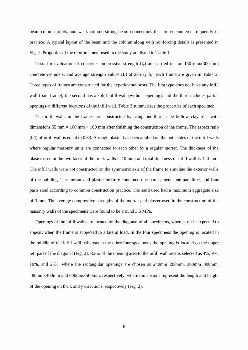
The infill walls in the frames are constructed by using one-third scale hollow clay tiles with
dimensions 55 mm × 100 mm × 100 mm after finishing the construction of the frame. The aspect ratio
(h/l) of infill wall is equal to 0.83. A rough plaster has been applied on the both sides of the infill walls
where regular masonry units are connected to each other by a regular mortar. The thickness of the
plaster used at the two faces of the brick walls is 10 mm, and total thickness of infill wall is 120 mm.
The infill walls were not constructed on the symmetric axis of the frame to simulate the exterior walls
of the building. The mortar and plaster mixture contained one part cement, one part lime, and four
parts sand according to common construction practice. The sand used had a maximum aggregate size
of 3 mm. The average compressive strengths of the mortar and plaster used in the construction of the
masonry walls of the specimens were found to be around 3.5 MPa.
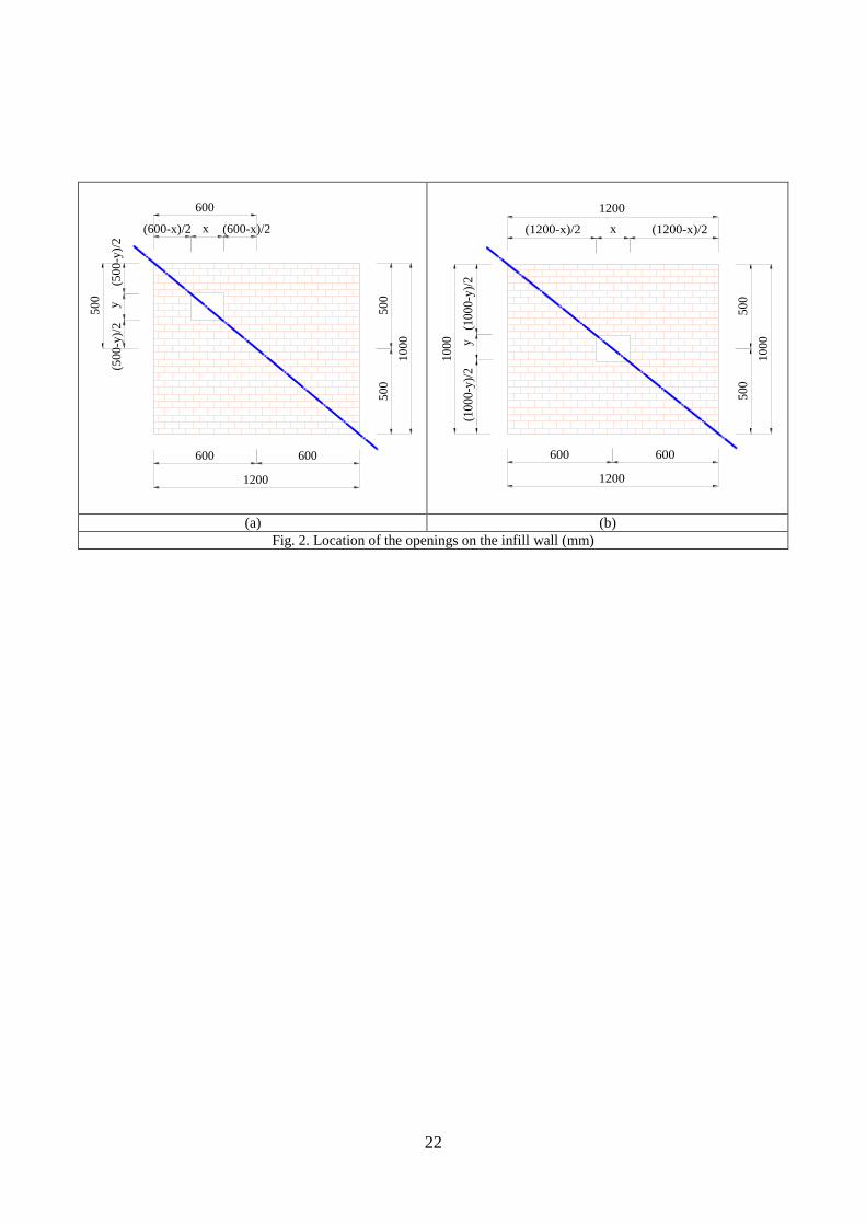
Openings of the infill walls are located on the diagonal of all specimens, where strut is expected to
appear, when the frame is subjected to a lateral load. In the four specimens the opening is located in
the middle of the infill wall, whereas in the other four specimens the opening is located on the upper
left part of the diagonal (Fig. 2). Ratio of the opening area to the infill wall area is selected as 4%, 9%,
16%, and 25%, where the rectangular openings are chosen as 240mm200mm, 360mm300mm,
480mm400mm and 600mm500mm, respectively, where dimensions represent the length and height
of the opening on the x and y directions, respectively (Fig. 2).
9
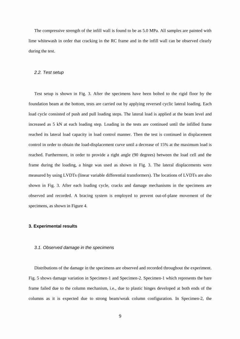
The compressive strength of the infill wall is found to be as 5.0 MPa. All samples are painted with
lime whitewash in order that cracking in the RC frame and in the infill wall can be observed clearly
during the test.
2.2. Test setup
Test setup is shown in Fig. 3. After the specimens have been bolted to the rigid floor by the
foundation beam at the bottom, tests are carried out by applying reversed cyclic lateral loading. Each
load cycle consisted of push and pull loading steps. The lateral load is applied at the beam level and
increased as 5 kN at each loading step. Loading in the tests are continued until the infilled frame
reached its lateral load capacity in load control manner. Then the test is continued in displacement
control in order to obtain the load-displacement curve until a decrease of 15% at the maximum load is
reached. Furthermore, in order to provide a right angle (90 degrees) between the load cell and the
frame during the loading, a hinge was used as shown in Fig. 3. The lateral displacements were
measured by using LVDTs (linear variable differential transformers). The locations of LVDTs are also
shown in Fig. 3. After each loading cycle, cracks and damage mechanisms in the specimens are
observed and recorded. A bracing system is employed to prevent out-of-plane movement of the
specimens, as shown in Figure 4.
3. Experimental results
3.1. Observed damage in the specimens
Distributions of the damage in the specimens are observed and recorded throughout the experiment.
Fig. 5 shows damage variation in Specimen-1 and Specimen-2. Specimen-1 which represents the bare
frame failed due to the column mechanism, i.e., due to plastic hinges developed at both ends of the
columns as it is expected due to strong beam/weak column configuration. In Specimen-2, the

10
separation cracks are firstly observed at the interface between the frame and the infill wall due to
deformation dissimilarity. While vertical cracks are formed at the bottom and top of the infill wall,
horizontal cracks are formed in the middle of the infill wall. Propagation of the horizontal cracking in
the middle of the infill wall developed a diagonal crack under increasing lateral load. After the
formation of a great number of hairline cracks on the infill wall, an increase in their widths is
observed, as well. The diagonal cracks in the infill wall were followed by shear failure at the bottom
and top of the columns. This is due to the shear force applied by the strut developed in the infill wall.
This fact indicates an increase of the design shear force at the columns as the horizontal component of
the strut, to avoid brittle shear failure at the columns.
Crack configurations observed in all specimens with the infill walls having openings are given in
Fig. 6. As seen, the first cracks occurred obliquely on the corner of the openings, where a stress
concentration is expected. Failure mechanisms of Specimens 3 and 4 are quite similar to that seen in
Specimen 2. Probable reason for this is that the size of the opening in the infill wall is quite small.
In Specimen 5, a crack was formed from the bottom corner of the opening up to the upper corner of
the frame. Later, the crack was widened under the increasing lateral load. The crack in the infill wall
was extended to the column at the frame corner and caused a shear failure at the top and bottom of the
column, as observed in Specimen 2.
Cracking in the infill walls took place outside the diagonal strip of the frame in Specimens 7 and 9,
while cracking took place along the diagonal of the frame in Specimens 6 and 8. Detailed inspection
shows that cracking in Specimen 7 took place in the area of the wall besides the opening obliquely
whereas a diagonal crack was formed in the area of the infill wall under the window opening in
Specimen 9. As a result of the increase in the crack width in these specimens, the infill walls were
failed by losing their load carrying capacity. In Specimen 10, the starting point of the crack was at the
window’s corner and the crack continued horizontally towards the column. From the experiments, it is
observed that the opening in infill walls has changed the basic behavior of the frame and created a new
failure mechanism, when the opening ratio is larger than 9%.
Generally it is observed that the failure mechanism of frames that include the infill walls with
opening depends mostly on the location and ratio of the openings.

11
3.2. Lateral load capacity of the specimens
Lateral load-displacement hysteretic curves that were obtained during the testing are illustrated in
Fig. 7. The tests show clearly that strength and stiffness of the frames increase significantly by the
presence of infill walls. The largest lateral load capacity has been obtained as 115 kN from Specimen-
2, whereas the lowest lateral load capacity has been obtained as 50 kN from Specimen-1. Lateral load
capacity of the specimen with the solid infill wall has increased by almost 130% as compared to the
specimen without infill wall. Envelope curves obtained from the lateral load–displacement hysteretic
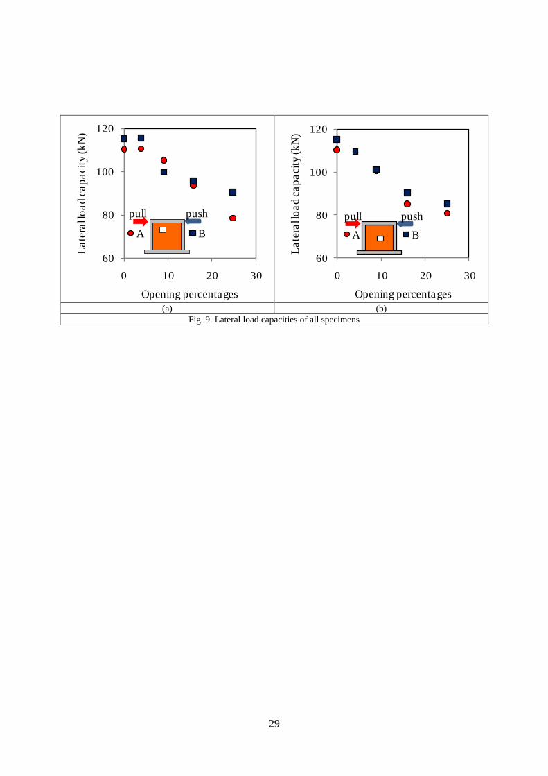
curves are shown in Fig. 8. Lateral load capacities obtained from the tests are given in Fig. 9
comparatively.
Lateral load capacity values in the pull and push directions are quite close to each other in the
specimens (Specimens 4, 6, 8, and 10) having opening in the middle of the infill wall. In contrast, in
the specimens (Specimens 3, 5, 7, and 9) having opening on the upper left part of the infill wall, the
lateral load capacities in the push direction are generally larger than the lateral load capacities in the
pull direction. A comparison of the two tests which have the same ratio of opening in the middle and
on the upper left part of the infill wall yields that the lateral load capacity of the former is generally
larger than the latter.
The lateral load capacities of Specimens 3 and 4 are almost equal to that of Specimen 2. As
expected, the test results yield that as the opening ratio increases, the lateral load capacity of the
specimen decreases, i.e., openings of 4, 9, 16 and 25 %, leads to a decrease in the lateral load capacity
of 1%, 10%, 20%, and 30%, respectively. It is worth noting that these values represent averages in
different opening locations and different loading directions. The results obtained from tests show that
the contribution of the infill walls to the lateral load capacity of the frame decreases significantly,
when the opening ratio is larger than 9%.
12
3.3. Story drift ratios
Story drift ratios are obtained for the all specimens in two different ways. Firstly, story
drift ratios are calculated for all specimens corresponding to a lateral load capacity (50 kN) of
the bare framed specimen. The highest and the lowest story drift ratios are observed in the
bare frame and solid infill walled specimen as 1.1% (0.86%) and 0.1% (0.13%), respectively
under pull (push) lateral loadings. The obtained results show that the story drift ratios increase
as the openings on the infill walls increase.
Secondly, story drift ratios corresponding to the ultimate load capacity of each specimen
are obtained. Except the specimens with the opening of 25%, the highest value for the story
drift ratio has been observed in bare frame while the lowest value has been observed in solid
infill walled frame. These corresponding drift values are at the order of 0.9-1.1% (0.7-0.9%)
under pull (push) lateral loadings except the specimens with the opening of 25%. In the
specimens with the opening of 25%, the story drift ratio is higher than the bare frame under
both push and pull loading. For example, Specimen 10 (with openings of 25%) has
experienced with 80 kN total load capacity, 1.4% story drift ratio and lateral stiffness of 5.05
kN/mm whereas, these values for bare frame are at the order of 50 kN, 1.1% and 4.16
kN/mm, respectively. This observation is due the fact that maximum story drift ratios are
proportional with the corresponding ultimate lateral load capacities of the Specimen 10 and 1.
Infill walls with openings contribute to the lateral stiffness and lateral load capacity of the
frames. However, if the opening in the infill wall is higher than 16%, story drift ratio
corresponding to the lateral load capacity of specimen is observed to increase with respect to
the bare frame. The obtained results clearly show that the effect of openings on story drift
ratios is noteworthy. Increment on the story drift ratio becomes significant when the opening
13
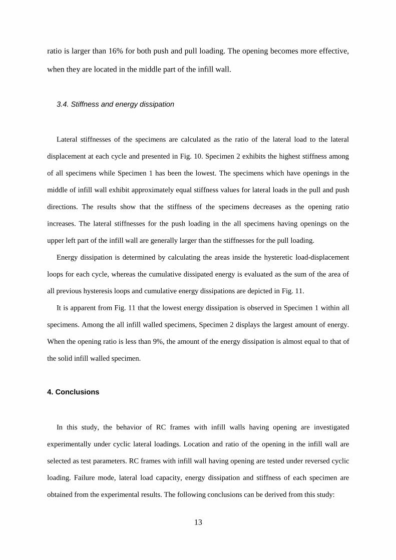
ratio is larger than 16% for both push and pull loading. The opening becomes more effective,
when they are located in the middle part of the infill wall.
3.4. Stiffness and energy dissipation
Lateral stiffnesses of the specimens are calculated as the ratio of the lateral load to the lateral
displacement at each cycle and presented in Fig. 10. Specimen 2 exhibits the highest stiffness among
of all specimens while Specimen 1 has been the lowest. The specimens which have openings in the
middle of infill wall exhibit approximately equal stiffness values for lateral loads in the pull and push
directions. The results show that the stiffness of the specimens decreases as the opening ratio
increases. The lateral stiffnesses for the push loading in the all specimens having openings on the
upper left part of the infill wall are generally larger than the stiffnesses for the pull loading.
Energy dissipation is determined by calculating the areas inside the hysteretic load-displacement
loops for each cycle, whereas the cumulative dissipated energy is evaluated as the sum of the area of
all previous hysteresis loops and cumulative energy dissipations are depicted in Fig. 11.
It is apparent from Fig. 11 that the lowest energy dissipation is observed in Specimen 1 within all
specimens. Among the all infill walled specimens, Specimen 2 displays the largest amount of energy.
When the opening ratio is less than 9%, the amount of the energy dissipation is almost equal to that of
the solid infill walled specimen.
4. Conclusions
In this study, the behavior of RC frames with infill walls having opening are investigated
experimentally under cyclic lateral loadings. Location and ratio of the opening in the infill wall are
selected as test parameters. RC frames with infill wall having opening are tested under reversed cyclic
loading. Failure mode, lateral load capacity, energy dissipation and stiffness of each specimen are
obtained from the experimental results. The following conclusions can be derived from this study:

14
(1) Presence of infill walls having openings changes the behavior of the frame significantly. It also
modifies the failure mechanism, as opening ratio increases, especially when it is larger than 9%.
(2) The obtained results have shown that infill walls lead to significant increases in strength and
stiffness in relation to bare RC frames. Lateral load capacity of the solid infill walled specimen
increases about 130% as compared to the specimen without infill wall. The test results show that as
the opening ratio increases, the lateral load capacity of the specimen decreases. When the opening
ratio of the infill wall is 4, 9, 16, and 25 %, the lateral load capacity decreases approximately 1, 10,
20, and 30%, respectively. Furthermore, the test results yield that the contribution of the infill wall
to the lateral load capacity of the frame decreases significantly, once the opening ratio is larger than
9%.
(3) Story drift ratios are obtained for the all specimens in two different ways. Firstly, story drift ratios
are calculated for all specimens corresponding to a lateral load capacity of the bare framed
specimen. The highest and the lowest story drift ratios are observed in the bare frame and solid
infill walled specimen. The obtained results show that the story drift ratios increase as the openings
on the infill walls increase.
(4) Secondly, story drift ratios corresponding to the ultimate load capacity of each specimen are
obtained. In the specimens with the opening of 25%, the story drift ratio is higher than the bare
frame under both push and pull loading. This observation is due the fact that maximum story drift
ratios are proportional with the corresponding ultimate lateral load capacities of the Specimen 10
and 1.
(5) Infill walls with openings contribute to the lateral stiffness and lateral load capacity of the frames.
However, if the opening in the infill wall is higher than 16%, story drift ratio corresponding to the
lateral load capacity of specimen is observed to increase with respect to the bare frame. The
obtained results clearly show that the effect of openings on story drift ratios is noteworthy.
Increment on the story drift ratio becomes significant when the opening ratio is larger than 16% for
both push and pull loading. The opening becomes more effective, when they are located in the
middle part of the infill wall.
15
(6) Energy dissipation and stiffness of the specimen is significantly reduced with the increase in the
ratio of the opening on the infill wall. Furthermore, the amount of energy dissipation is almost
equal to that of the solid infill walled specimen, when the opening ratio is more than 9%.
(7) Behavior of the specimen under pull and push loading are quite close to each other, when the
opening is located in the middle of the infill wall. However, the pull loading is generally more
critical than the push loading, when the behavior of the specimen is considered, especially and
when the opening is located on the upper left part of the infill.
(8) The test results clearly show that the contribution of the infill wall to the behavior of RC frame has
greatly reduced, when the opening ratio is larger than 9%. Therefore, the effect of the opening in
the infill wall must be taken into account in the structural modeling, when the opening ratio is
larger than 9%.
(9) In order to avoid brittle shear failure at the top and bottom of the columns of the frames with infill,
the design shear force should be increased by the horizontal component of the strut developed in
the infill wall.
(10) Experimental tests have shown that presence of openings significantly change the behavior of
infilled frames. The macro model of infill wall with opening can be developed by using the
experimental results. Empirical equations can be proposed for estimating changes in lateral load
capacity, energy dissipation, and the lateral stiffness of infill walled frames because of the presence
of openings.
Acknowledgements
The study presented in this article was sponsored by the Research Project Coordination Unit of
Suleyman Demirel University (SDU) under Project No. 3418-YL1-13 and Kelesoglu Construction
Company. The experimental work of this study was conducted in the Structural and Earthquake
Engineering Laboratory at SDU. The authors would like to thank Mr. Osman Akyurek, Mr. Metin
Deniz, Mr. Necmi Kara, Mr. Emircan Hersat, Mr. Uğur Tosun, and Mr. Fatih Kaya for their assistance
in conducting the experiments.
16
References
[1] Dolsek, M. and Fajfar, P. “The effect of masonry infills on the seismic response of a four-storey
reinforced concrete frame a deterministic assessment”, Engineering Structures, 30, 1991–2001
(2008).
[2] Uva, G., Raffaele, D., Porco, F. and Fiore, A. “On the role of equivalent strut models in the seismic
assessment of infilled RC buildings”, Engineering Structures, 42, 83–94 (2012).
[3] Chrysostomou, C.Z. and Asteris, P.G. “On the in-plane properties and capacities of infilled
frames”, Engineering Structures, 41, 385–402 (2012).
[4] Ricci, P., Verderame, G.M. and Manfredi, G. “Analytical investigation of elastic period of infilled
RC MRF buildings”, Engineering Structures, 33, 308–319 (2011).
[5] Shing, P.B. and Mehrabi, A.B. “Behavior and analysis of masonry-infilled frames”, Prog. Struct.
Engng Mater., 4, 320–331 (2002).
[6] Koutromanos, I., Stavridis, A., Shing, P.B. and Willam, K. “Numerical modeling of masonry-
infilled RC frames subjected to seismic loads”, Computers and Structures, 89, 1026–1037 (2011).
[7] Celarec, D., Ricci, P. and Dolšek, M. “The sensitivity of seismic response parameters to the
uncertain modelling variables of masonry-infilled reinforced concrete frames”, Engineering
Structures, 35, 165–177 (2012).
[8] Campione, G. , Cavaleri, L., Macaluso, G., and Amato, G., “Evaluation of infilled frames: an
updated in-plane-stiffness macro-model considering the effects of vertical loads”, Bull
Earthquake Eng, 13, 2265–2281 (2015).
[9] Martinelli, E., Lima, C., and Stefano, G.D., “A simplified procedure for Nonlinear Static analysis
of masonry infilled RC frames”, Engineering Structures, 101, 591–608 (2015).
[10] Amanat, K.M. and Hoque, E. “A rationale for determining the natural period of RC building
frames having infill”, Engineering Structures, 28, 495–502 (2006).
[11] Kose, M.M. “Parameters affecting the fundamental period of RC buildings with infill walls”,
Engineering Structures, 31, 93-102 (2009).

17
[12] Asteris, P.G., Repapis, C., Tsaris, A.K., and Cavaleri, L., “Parameters affecting the fundamental
period of infilled RC frame structures”, Earthquakes and Structures, 9(5), 999-1028 (2015).
[13] Pujol, S. and Fick, D. “The test of a full-scale three-story RC structure with masonry infill walls”,
Engineering Structures, 32, 3112-3121 (2010).
[14] Tu, Y.H., Chuan, T.H., Liu, P.M. and Yang, Y.S. “Out-of-plane shaking table tests on
unreinforced masonry panels in RC frames”, Engineering Structures, 32, 3925–3935 (2010).
[15] Arulselvan, S., Subramanian, K., Perumalpillai, E.B. and Santhakumar, A.R. “RC infilled frame-
RC plane frame interactions for seismic resistance”, Journal of Applied Sciences, 7(7), 942-950
(2007).
[16] Asteris, P.G. “Lateral stiffness of brick masonry infilled plane frames”, Journal of Structural
Engineering, 129(8), 1071–1079 (2003).
[17] Altin, S., Ersoy, U. and Tankut, T. “Hysteretic response of reinforced concrete infilled frames”,
Journal of Structural Engineering, 118(8), 2133-2150 (1992).
[18] Anil, O. and Altin, S. “Experimental study on reinforced concrete partially infilled frames”,
Engineering Structures, 29, 449-460 (2007).
[19] Tasnimi, A.A. and Mohebkhah, A. “Investigation on the behavior of brick-infilled steel frames
with openings, experimental and analytical approaches”, Engineering Structures, 33, 968–980
(2011).
[20] Liu, Y. and Manesh, P. “Concrete masonry infilled steel frames subjected to combined in-plane
lateral and axial loading – An experimental study”, Engineering Structures, 52, 331–339 (2013).
[21] Voon, K.C. and Ingham, J.M. “Experimental in-plane strength investigation of reinforced
concrete masonry walls with openings”, Journal of Structural Engineering, 134(5), 758-768
(2008).
[22] Kakaletsis, D.J., Karayannis, C.G. “Experimental investigation of infilled reinforced concrete
frames with openings”, ACI Structural Journal, 106(2), 132-141 (2009).
[23] Mansouri, A., Marefat, M.S. and Khanmohammadi, M. “Experimental evaluation of seismic
performance of low-shear strength masonry infills with openings in reinforced concrete frames
with deficient seismic details”, Struct. Design Tall Spec. Build., 23(15), 1190-1210 (2013).

18
[24] Evaluation of Earthquake Damaged Concrete and Masonry Wall Buildings, prepared by the
Applied Technology Council (ATC-43 project) for the Partnership for Response and Recovery.
Federal Emergency Management Agency, Report No. FEMA-306, Washington, D.C., (1999).
19
List of Figures
Fig. 1. Dimensions and reinforcement details of the specimens (mm)
Fig. 2. Location of the openings on the infill wall (mm)
Fig. 3. Test setup
Fig. 4. Bracing system against out-of-plane movement of the specimens
Fig. 5. Damage observed in Specimen-1 and Specimen-2
Fig. 6. Damage observed in all specimens with the infill wall which have opening
Fig. 7. Lateral load–displacement hysteretic curves of all specimens
Fig. 8. Envelope curves for all specimens
Fig. 9. Lateral load capacities of all specimens
Fig. 10. Variation of stiffness depending on displacement for all specimens
Fig. 11. Energy dissipation depending on displacement for all specimens

20
List of Tables
Table 1. Average values of the yield stress of the reinforcing bars
Table 2. Location and ratio of the opening on infill wall

21
Fig. 1. Dimensions and reinforcement details of the specimens (mm)
610 410
516
216
516
150 300 150600
250 150 1200 150 250
2000
140
30
140
400
150
150
150
200
400
1000
20
0
1600
CC
CC
140
30
190
22
(a) (b)
Fig. 2. Location of the openings on the infill wall (mm)
600 600
1200
500
500
1000
x
600
(600-x)/2
y
500
(500-y
)/2
(600-x)/2
(500-y
)/2
600 600
1200
500
500
1000
x
1200
(1200-x)/2
y
1000
(1000-y
)/2
(1000-y
)/2
(1200-x)/2

23
Fig. 3. Test setup

24
Fig. 4. Bracing system against out-of-plane movement of the specimens

25
(a) Specimen-1 (b) Specimen-2
Fig. 5. Damage observed in Specimen-1 and Specimen-2

26
(a) Specimen 3 (b) Specimen 4
(c) Specimen 5 (d) Specimen 6
(e) Specimen 7 (f) Specimen 8
(g) Specimen 9 (h) Specimen 10
Fig. 6. Damage observed in all specimens with the infill wall which have opening

27
(a) (b)
(c) (d)
(e) (f)
(g) (h)
(i) (j)
Fig. 7. Lateral load–displacement hysteretic curves of all specimens
-150
-100
-50
0
50
100
150
-90 -60 -30 0 30 60 90
Lat
eral
lo
ad (
kN
)
Displacement (mm)
SPECIMEN-1
-150
-100
-50
0
50
100
150
-90 -60 -30 0 30 60 90
Lat
eral
load
(kN
)
Displacement (mm)
SPECIMEN-2
-150
-100
-50
0
50
100
150
-90 -60 -30 0 30 60 90
Lat
eral
lo
ad (
kN
)
Displacement (mm)
SPECIMEN-3
-150
-100
-50
0
50
100
150
-90 -60 -30 0 30 60 90
Lat
eral
lo
ad (
kN
) Displacement (mm)
SPECIMEN-4
-150
-100
-50
0
50
100
150
-90 -60 -30 0 30 60 90
Lat
eral
load
(kN
)
Displacement (mm)
SPECIMEN-5
-150
-100
-50
0
50
100
150
-90 -60 -30 0 30 60 90
Lat
eral
load
(kN
)
Displacement (mm)
SPECIMEN-6
-150
-100
-50
0
50
100
150
-90 -60 -30 0 30 60 90
Lat
eral
load
(kN
)
Displacement (mm)
SPECIMEN-7
-150
-100
-50
0
50
100
150
-90 -60 -30 0 30 60 90
Lat
eral
load
(kN
)
Displacement (mm)
SPECIMEN-8
-150
-100
-50
0
50
100
150
-90 -60 -30 0 30 60 90
Lat
eral
lo
ad (
kN
)
Displacement (mm)
SPECIMEN-9
-150
-100
-50
0
50
100
150
-90 -60 -30 0 30 60 90
Lat
eral
lo
ad (
kN
)
Displacement (mm)
SPECIMEN-10

28
(a) (b)
Fig. 8. Envelope curves for all specimens
-150
-100
-50
0
50
100
150
-60 -40 -20 0 20 40 60
Lat
eral
load
(kN
)
Displacement (mm)
Specimen-1 Specimen-2Specimen-3 Specimen-5Specimen-7 Specimen-9
push
pull
-150
-100
-50
0
50
100
150
-60 -40 -20 0 20 40 60
Lat
eral
load
(kN
)
Displacement (mm)
Specimen-1 Specimen-2Specimen-4 Specimen-6Specimen-8 Specimen-10
pull
push
29
(a) (b)
Fig. 9. Lateral load capacities of all specimens
60
80
100
120
0 10 20 30
La
tera
l lo
ad
ca
pa
cit
y (k
N)
Opening percentages
A B
pull push
60
80
100
120
0 10 20 30
La
tera
l lo
ad
ca
pa
cit
y (k
N)
Opening percentages
A B
pull push

30
(a) (b)
Fig. 10. Variation of stiffness depending on displacement for all specimens
0
5
10
15
20
-30 -20 -10 0 10 20 30
Sti
ffnes
s (k
N/m
m)
Displacement (mm)
Specimen-1 Specimen-2Specimen-3 Specimen-5Specimen-7 Specimen-9
pull
push
0
5
10
15
20
-30 -20 -10 0 10 20 30
Sti
ffnes
s (k
N/m
m)
Displacement (mm)
Specimen-1 Specimen-2Specimen-4 Specimen-6Specimen-8 Specimen-10
pull push

31
(a) (b)
Fig. 11. Energy dissipation depending on displacement for all specimens
0
1000
2000
3000
4000
5000
-60 -40 -20 0 20 40 60Ener
gy d
issi
pat
ion (
kN
mm
)
Displacement (mm)
Specimen-1 Specimen-2Specimen-3 Specimen-5Specimen-7 Specimen-9
pull
push
0
1000
2000
3000
4000
5000
-60 -40 -20 0 20 40 60Ener
gy d
issi
pat
ion (
kN
mm
)
Displacement (mm)
Specimen-1 Specimen-2Specimen-4 Specimen-6Specimen-8 Specimen-10
pull push

32
Table 1. Average values of the yield stress of the reinforcing bars
Bar diameter (mm) fsy (MPa) fsu (MPa)
6 374 476
10 449 524
16 452 536

33
Table 2. Location and ratio of the opening on infill wall
Specimen
ID
fc
(MPa)
Frame
Opening
percentage
%
Opening
position
Specimen
ID
fc
(MPa)
Frame
Opening
percentage
%
Opening
position
Specimen-1 21 100
Specimen-2 20 0
Specimen-3 23 4
Specimen-4 21 4
Specimen-5 21 9
Specimen-6 21 9
Specimen-7 22 16
Specimen-8 20 16
Specimen-9 20 25
Specimen-10 22 25