AN EXPERIMENTAL STUDY ON DESIGN OF CONNECTING … filereciprocating motion of the piston into...
15
INTERNATIONAL JOURNAL OF RESEARCH IN AERONAUTICAL AND MECHANICAL ENGINEERING WWW.IJRAME.COM ISSN (ONLINE): 2321-3051 Vol.5 Issue.6, June 2017 Pg: -32-46 Jitender Dahiya 32 AN EXPERIMENTAL STUDY ON DESIGN OF CONNECTING ROD FOR A MOTORBIKE Jitender Dahiya*, Ashish Saxena** *Assistant Professor, Department of Mechanical Engineering, Faculty of Engineering & Technology, Manav Rachna International University, Haryana **Assistant Professor, Department of Mechanical Engineering, Faculty of Engineering & Technology, Manav Rachna International University, Haryana (Corresponding Author: Jitender Dahiya) ABSTRACT: In the engine of the automobile, connecting rod is a high volume production and critical component. The Connecting rod connects piston and the crankshaft, and it is responsible to transmit the power from the piston to crankshaft thus, converting the reciprocating motion of the piston into rotating motion of the crankshaft. Generally, connecting rods which are manufactured using carbon steel and composite materials are finding their use in industry. In vehicle engines, the connecting rod is subjected application to high cyclic loads. High compressive loads are due to combustion in the cylinder of the automobile engine, and high tensile loads are due to weight of the connecting rod. The main objective of the present work is to review the weight optimization of a connecting rod in vehicle engine at different loads. To get the idea about designing the connecting rod, various stresses are considered while designing the connecting rod and epoxy resin is used as base material. To get the idea about designing the connecting rod by Finite Element Method (FEM) using ANSYS WORKBENCH 9.0 software for the modelling and analysis of connecting rod. Keywords: Reciprocating motion, Cyclic loads, Compressive loads, Weight optimization, Finite Element Method, Epoxy resin, Modelling & analysis INTRODUCTION: A Connecting rod is the link between the rotating crank shaft and reciprocating piston. Small end of the connecting rod is connected to the piston. The big end of the connecting rod is connected to the crankshaft. The main function of the connecting rod is to transform the reciprocating motion of the piston into the rotary motion of the crankshaft. The connecting rods are generally manufactured by forging & casting. However, with the progress of technology, the connecting rods present days are also cast from malleable or spheroid graphite cast iron, depending upon the requirements. In general, forged connecting rod are
Transcript of AN EXPERIMENTAL STUDY ON DESIGN OF CONNECTING … filereciprocating motion of the piston into...

INTERNATIONAL JOURNAL OF RESEARCH IN AERONAUTICAL AND MECHANICAL ENGINEERING
WWW.IJRAME.COM ISSN (ONLINE): 2321-3051
Vol.5 Issue.6, June 2017 Pg: -32-46
Jitender Dahiya
32
AN EXPERIMENTAL STUDY ON DESIGN OF CONNECTING ROD
FOR A MOTORBIKE Jitender Dahiya*, Ashish Saxena**
*Assistant Professor, Department of Mechanical Engineering, Faculty of Engineering & Technology, Manav
Rachna International University, Haryana
**Assistant Professor, Department of Mechanical Engineering, Faculty of Engineering & Technology, Manav
Rachna International University, Haryana
(Corresponding Author: Jitender Dahiya)
ABSTRACT:
In the engine of the automobile, connecting rod is a high volume production and critical
component. The Connecting rod connects piston and the crankshaft, and it is
responsible to transmit the power from the piston to crankshaft thus, converting the
reciprocating motion of the piston into rotating motion of the crankshaft. Generally,
connecting rods which are manufactured using carbon steel and composite materials
are finding their use in industry. In vehicle engines, the connecting rod is subjected
application to high cyclic loads. High compressive loads are due to combustion in the
cylinder of the automobile engine, and high tensile loads are due to weight of the
connecting rod. The main objective of the present work is to review the weight
optimization of a connecting rod in vehicle engine at different loads. To get the idea
about designing the connecting rod, various stresses are considered while designing the
connecting rod and epoxy resin is used as base material. To get the idea about designing
the connecting rod by Finite Element Method (FEM) using ANSYS WORKBENCH 9.0
software for the modelling and analysis of connecting rod.
Keywords: Reciprocating motion, Cyclic loads, Compressive loads, Weight optimization,
Finite Element Method, Epoxy resin, Modelling & analysis
INTRODUCTION:
A Connecting rod is the link between the rotating crank shaft and reciprocating piston. Small
end of the connecting rod is connected to the piston. The big end of the connecting rod is
connected to the crankshaft. The main function of the connecting rod is to transform the
reciprocating motion of the piston into the rotary motion of the crankshaft. The connecting
rods are generally manufactured by forging & casting. However, with the progress of
technology, the connecting rods present days are also cast from malleable or spheroid
graphite cast iron, depending upon the requirements. In general, forged connecting rod are

INTERNATIONAL JOURNAL OF RESEARCH IN AERONAUTICAL AND MECHANICAL ENGINEERING
WWW.IJRAME.COM ISSN (ONLINE): 2321-3051
Vol.5 Issue.6, June 2017 Pg: -32-46
Jitender Dahiya
33
compact in design and light in weight which is an advantage from inertia view point. It has
consist of mainly three parts namely- a pin end, a shank region and a crank end. The pin end
is connected to the piston and crank end is connected to crankshaft. A combination of axial
and bending stresses act on the rod in operation. The axial stresses are generated due to
cylinder gas pressure and the inertia force arising on account of reciprocating motion.
Whereas bending stresses are produced due to the centrifugal effects. To provide the
maximum rigidity with minimum weight, the cross section of the connecting rod is made as I
– section. The ends of the connecting rod is a solid eye or a split eye, this end holding the
piston pin. The big end works on the crank pin and is always split. In some connecting rods, a
hole is drilling between two ends for carrying lubricating oil from the big end to the small
end for lubrication of piston and the piston pin.
Design of Connecting Rod:
In designing a connecting rod the following dimensions are required to be determined:
1. Dimension of cross section of connecting rod
2. Dimension of the crank pin at the big end and the piston pin at the small end
3. Size of the bolts for securing the big end cap
4. Thickness of the big end cap
Force Calculation
Load due to gas pressure on piston (Fg)
Fg = (π d2
÷ 4)*p .max
Inertia force due to reciprocating parts
(Fi)
Where, W = Weight of reciprocating parts in N
r = Crank radius
1
22
1000
n
CosCos
gr
WrV
F i

INTERNATIONAL JOURNAL OF RESEARCH IN AERONAUTICAL AND MECHANICAL ENGINEERING
WWW.IJRAME.COM ISSN (ONLINE): 2321-3051
Vol.5 Issue.6, June 2017 Pg: -32-46
Jitender Dahiya
34
= Crank angle from the dead centre
V = Crank velocity m/s
r
ln
1
l= length of connecting rod, r = crank radius
So, total force on connecting rod, (F) =
Fg + Fi
Material Properties
Material selected Epoxy Resin
Mass density of the Material (ρ), Kg/mm3 2.6* 103
Tensile modulus along X-direction (Ex), MPa 34000
Tensile modulus along Y-direction (Ex), MPa 6530
Tensile modulus along Z-direction (Ex), MPa 6530
Tensile strength of the material, MPa 900
Compressive strength of the material, MPa 450
Shear modulus along XY-direction (Gxy), MPa 2433
Shear modulus along YZ-direction (Gyz), MPa 1698
Shear modulus along ZX-direction (Gzx), MPa 2433
Poisson ratio along XY-direction (NUxy) 0.217
Poisson ratio along YZ-direction (NUyz) 0.366
Poisson ratio along ZX-direction (NUzx) 0.217
Table 1: Material Properties for Connecting Rod
INTERNATIONAL JOURNAL OF RESEARCH IN AERONAUTICAL AND MECHANICAL ENGINEERING
WWW.IJRAME.COM ISSN (ONLINE): 2321-3051
Vol.5 Issue.6, June 2017 Pg: -32-46
Jitender Dahiya
35
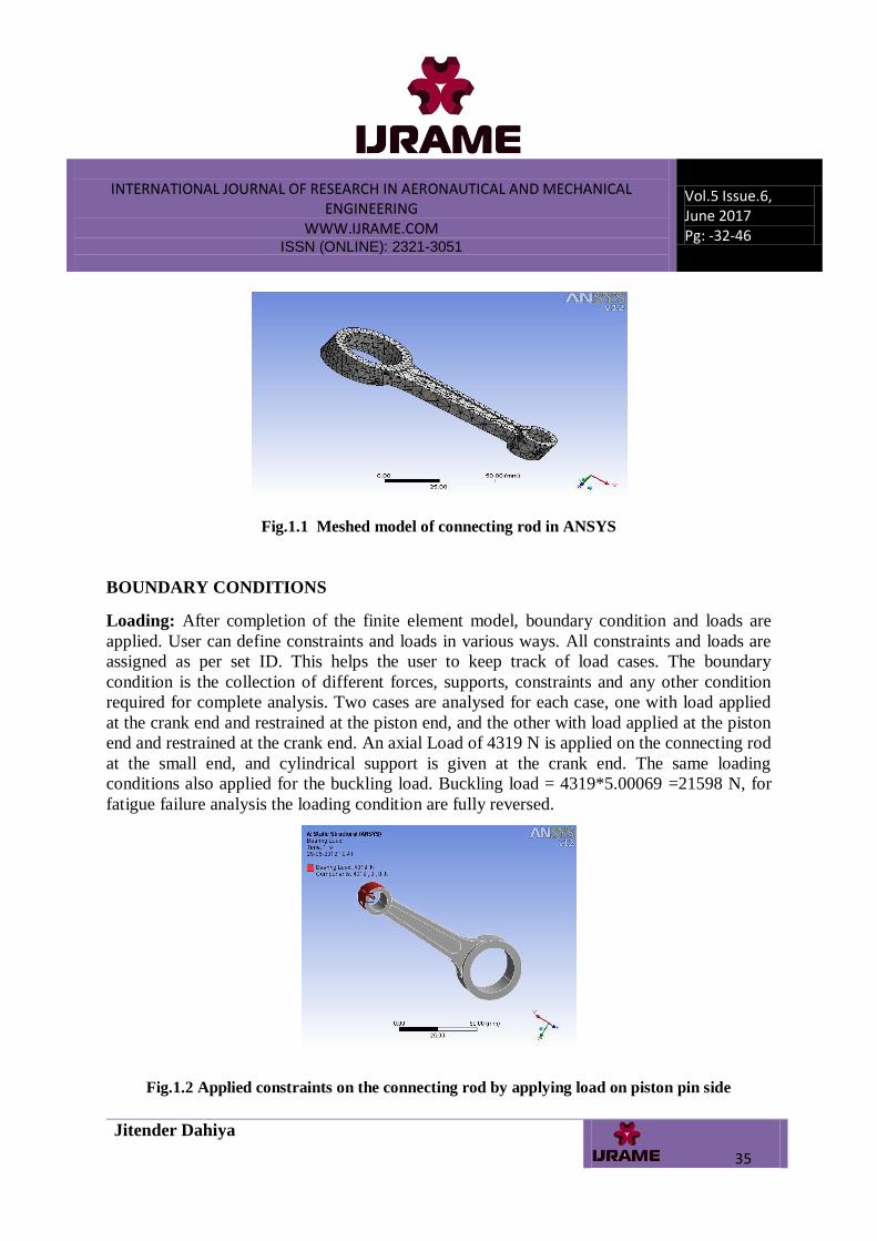
Fig.1.1 Meshed model of connecting rod in ANSYS
BOUNDARY CONDITIONS
Loading: After completion of the finite element model, boundary condition and loads are
applied. User can define constraints and loads in various ways. All constraints and loads are
assigned as per set ID. This helps the user to keep track of load cases. The boundary
condition is the collection of different forces, supports, constraints and any other condition
required for complete analysis. Two cases are analysed for each case, one with load applied
at the crank end and restrained at the piston end, and the other with load applied at the piston
end and restrained at the crank end. An axial Load of 4319 N is applied on the connecting rod
at the small end, and cylindrical support is given at the crank end. The same loading
conditions also applied for the buckling load. Buckling load = 4319*5.00069 =21598 N, for
fatigue failure analysis the loading condition are fully reversed.
Fig.1.2 Applied constraints on the connecting rod by applying load on piston pin side

INTERNATIONAL JOURNAL OF RESEARCH IN AERONAUTICAL AND MECHANICAL ENGINEERING
WWW.IJRAME.COM ISSN (ONLINE): 2321-3051
Vol.5 Issue.6, June 2017 Pg: -32-46
Jitender Dahiya
36
Fig.1.3 Applied constraints on the connecting rod by applying cylindrical support at another
side
FEA RESULTS FOR AXIAL LOAD (8638N)
Fig.1.4 Equivalent (Von-Mises) Stress (for load =8638N)
INTERNATIONAL JOURNAL OF RESEARCH IN AERONAUTICAL AND MECHANICAL ENGINEERING
WWW.IJRAME.COM ISSN (ONLINE): 2321-3051
Vol.5 Issue.6, June 2017 Pg: -32-46
Jitender Dahiya
37
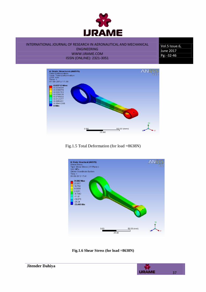
Fig.1.5 Total Deformation (for load =8638N)
Fig.1.6 Shear Stress (for load =8638N)
INTERNATIONAL JOURNAL OF RESEARCH IN AERONAUTICAL AND MECHANICAL ENGINEERING
WWW.IJRAME.COM ISSN (ONLINE): 2321-3051
Vol.5 Issue.6, June 2017 Pg: -32-46
Jitender Dahiya
38
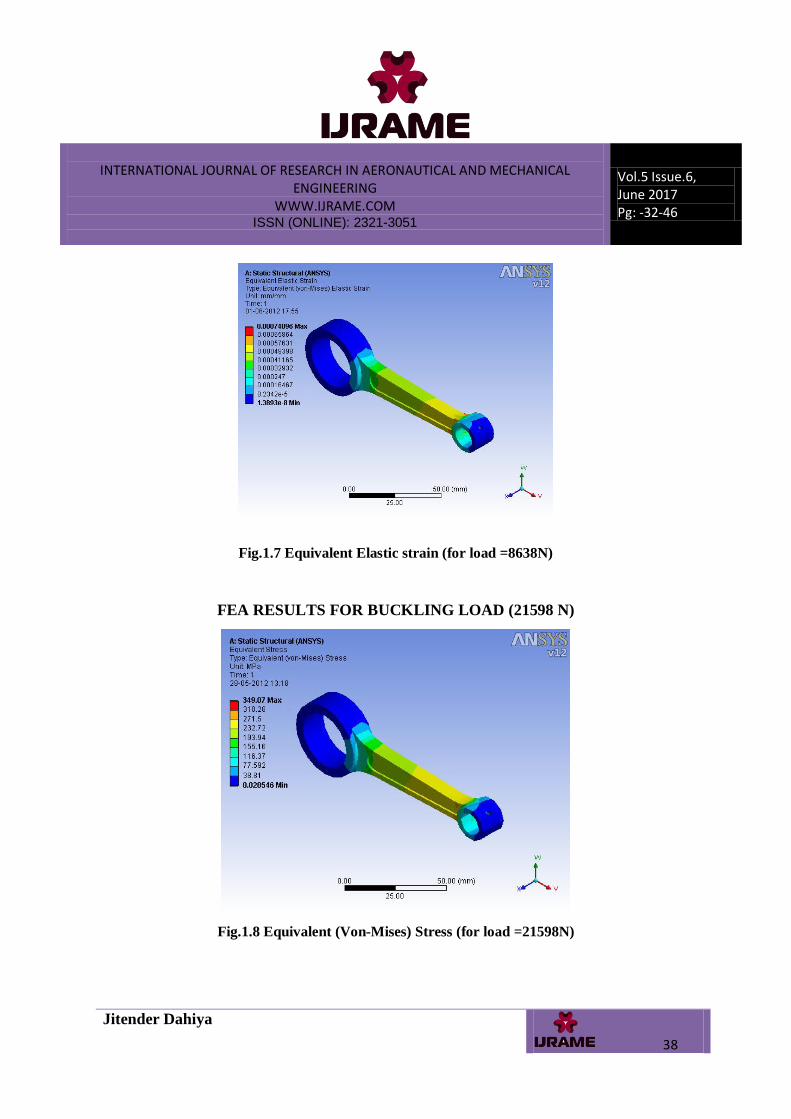
Fig.1.7 Equivalent Elastic strain (for load =8638N)
FEA RESULTS FOR BUCKLING LOAD (21598 N)
Fig.1.8 Equivalent (Von-Mises) Stress (for load =21598N)

INTERNATIONAL JOURNAL OF RESEARCH IN AERONAUTICAL AND MECHANICAL ENGINEERING
WWW.IJRAME.COM ISSN (ONLINE): 2321-3051
Vol.5 Issue.6, June 2017 Pg: -32-46
Jitender Dahiya
39
Fig.1.9 Shear Stress (for load =21598N)
Fig.1.10 Equivalent Elastic strain (for load =21598N)

INTERNATIONAL JOURNAL OF RESEARCH IN AERONAUTICAL AND MECHANICAL ENGINEERING
WWW.IJRAME.COM ISSN (ONLINE): 2321-3051
Vol.5 Issue.6, June 2017 Pg: -32-46
Jitender Dahiya
40
Fig.1.11Total deformation (for load =21598N)
FATIGUE FAILURE RESULTS FOR BUCKLING LOAD (21598 N)
Fig.1.12 Applied constraints on connecting rod (for load=21598N)
INTERNATIONAL JOURNAL OF RESEARCH IN AERONAUTICAL AND MECHANICAL ENGINEERING
WWW.IJRAME.COM ISSN (ONLINE): 2321-3051
Vol.5 Issue.6, June 2017 Pg: -32-46
Jitender Dahiya
41
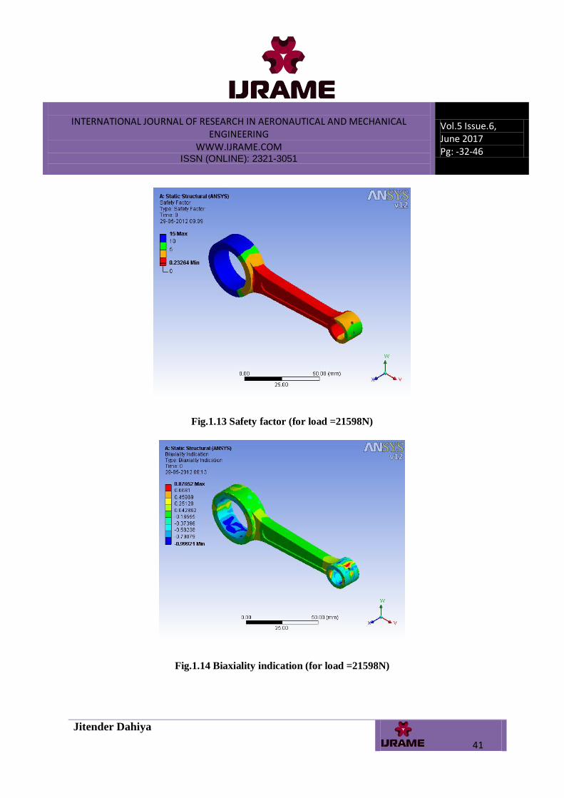
Fig.1.13 Safety factor (for load =21598N)
Fig.1.14 Biaxiality indication (for load =21598N)

INTERNATIONAL JOURNAL OF RESEARCH IN AERONAUTICAL AND MECHANICAL ENGINEERING
WWW.IJRAME.COM ISSN (ONLINE): 2321-3051
Vol.5 Issue.6, June 2017 Pg: -32-46
Jitender Dahiya
42
Fig.1.15 Damage (for load =21598N)
Fig.1.16 Life (for load =21598N)
COMPARISON OF FINITE ELEMENT ANALYSIS RESULTS OF
PRESENT MODEL
The FEA results are in close agreement with the existing results. The variation in the Von-
Mises stress found to be2.78%. The variation in the shear stress found to be 5.4%.And the
variation in elastic strain is 2.6%. So the FEA results are better than the existing results.

INTERNATIONAL JOURNAL OF RESEARCH IN AERONAUTICAL AND MECHANICAL ENGINEERING
WWW.IJRAME.COM ISSN (ONLINE): 2321-3051
Vol.5 Issue.6, June 2017 Pg: -32-46
Jitender Dahiya
43
After thoroughly examining the FEA results the stresses and strain in the designed model is
much below the yield limit. The present design is acceptable and safe for further dynamic
simulation.
Result comparison (for static analysis)
Sr. n
o.
Pa
ram
ete
rs
Existing
result
for
buckling
load(215
98N)
FEA
result
for
bucklin
g
load(21
598N)
Variati
on for
load
(21598
N)
1
Equivalent
von-
Misses
stress
381.17
MPa
349.07
Mpa
8.4%
2 Shear
stress
82.21
MPa
47.941
MPa
41.6%
3 Elastic
strain
1.91e-3
mm/mm
1.74e-3
mm/m
m
8.9%
4
Total
deformatio
n
_
.091034
mm
_
Table No.2: Result Comparisons for static analysis

INTERNATIONAL JOURNAL OF RESEARCH IN AERONAUTICAL AND MECHANICAL ENGINEERING
WWW.IJRAME.COM ISSN (ONLINE): 2321-3051
Vol.5 Issue.6, June 2017 Pg: -32-46
Jitender Dahiya
44
Result comparison (for fatigue analysis)
Table No. 3: Result Comparisons for fatigue analysis
CONCLUSION: The model taken under study has been reviewed thoroughly and it is safe
and under permissible limits of applied stresses. The weight parameter of the experimental
connecting rod with modification gives sufficient improvement in the prior existing results.
Fatigue strength is the crucial parameter of a connecting rod and after modification the
fatigue results are in good agreement with the existing results. The maximum stress found at
the piston end is reduced by increasing the material near the piston end.
REFERENCES
[1] Pravardhan S. Shenoy and Ali Fatemi “Connecting Rod Optimization for Weight and Cost Reduction”,
2005, SAE International.
[2] A. Mirehei, M. Hedayati Zadeh, A. Jafari, and M. Omid “Fatigue analysis of connecting rod of universal
tractor through finite element method (ANSYS)” Journal of Agricultural Technology,2008, Vol.4, pp 21-27.
[3] Dilip G. Gangwani, and Prof. R.M. Metkar “Computer Aided Modelling and Finite Element Analysis of
Connecting Rod Fouling on Camshaft of DI Engine of Mahindra and Mahindra Tractor” Second International
Conference on Emerging Trends in Engineering and Technology, ICETET-09.
Sr. N
o.
Param
ete
r Existing result for
buckling
load(21598N)
FEA results for
buckling
load(21598N)
min max min max
1. Life 3138.61 1e6 3425 .6 1e6
2. Safety
factor 0.23 15 0.23264 15
3. Biaxiality
indication -1.0 0.97 -0.999 0.876
4.
Damage 1000 318612.78 1000 2.9192

INTERNATIONAL JOURNAL OF RESEARCH IN AERONAUTICAL AND MECHANICAL ENGINEERING
WWW.IJRAME.COM ISSN (ONLINE): 2321-3051
Vol.5 Issue.6, June 2017 Pg: -32-46
Jitender Dahiya
45
[4] Yang Kun, OuYang Guangyao, and Yi Tailian Ye Lina “Computer Aided Numerical Analysis upon the
Connecting Rod Bearing Cave Corroding Fault”,WASE International Conference on Information
Engineering,2009.
[5] Xianjun Hou, Cuicui Tian, Dan Fang, Fuming Peng and Fuwu Yan “Sensitivity Analysis and Optimization
for Connecting Rod of LJ276M Electronic Gasoline Engine”, published by IEEE,2009, pp 978.
[6] Mansour Rasekh, Mohammad Reza Asadi, Ali Jafari, and Kamran Kheiralipour “Obtaining Maximum
Stresses in Different Parts of Tractor (Mf-285) Connecting Rods Using Finite Element Method”. Australian
Journal of Basic and Applied Sciences, 2009,Vol.3, pp 1438-1449.
[7] Mr. Pranav G Charkha and Dr Santosh B Jaju “Analysis & Optimization of Connecting Rod” Second
International Conference on Emerging Trends in Engineering and Technology, ICETET-09.
\[8]Asadi, M.R., Rasekh, M., Golmohammadi, A. Jafari, A., Kheiralipour, K. and Borghei, A.M.“Optimization
of connecting rod of MF-285 tractor” Journal of Agricultural Technology, 2010, Vol.6, pp 649-662.
[9] Wei ZhanGuo Liu and Yu Ying “The Design of Forestry Harvesting Machines Connecting Rod based on
Finite Element Analysis” ICMET 2010.
[10] Zhou Qinghui, Wang Yunying and Ji Wei “The Finite Element Analysis of Connecting Rod of Diesel
Engine”, 2010.
[11] Zheng Bin Liu Yongqi and Ji Lixia “Finite Element Analysis and Structural Improvement of Diesel Engine
Connecting rod”, Second International Conference on Computer Modeling and Simulation,2010.
[12] Deng Banglin, Liu Jingping, Yang Jing, Feng Renhua, Fu Jianqin, and Chen Shanping “Fatigue and
Bearing Analysis of An Engine Connecting Rod Based on Multi-body Dynamics”, Third International
Conference on Measuring Technology and Mechatronics Automation,2011.
[13] Vasile George Ciotia, Imre Kiss “Computer aided design of the connecting rod”.
[14] Zhiwei Tong, HaoLiu, and Fengxia Zhu “Modal Analysis for Connecting Rod of reciprocating mud
Pump.”
[15] www.matweb.com.
[16] V.B. Bhandari, Sharma. & Agarwal “Books of machine design”.
[17] CATIA V5 - R19 manual.

INTERNATIONAL JOURNAL OF RESEARCH IN AERONAUTICAL AND MECHANICAL ENGINEERING
WWW.IJRAME.COM ISSN (ONLINE): 2321-3051
Vol.5 Issue.6, June 2017 Pg: -32-46
Jitender Dahiya
46
[18] Solid works.
[19] ANSYS 12 Workbench.
[20] P.C Punamia “ Books Of Strength Of Material”
[21] M. M. Patunkar & D. R. Dolas “Epoxy Resin Material used for Leaf Spring”
[22] S. M. AthavaIe & J. S. Strenkowski “ Modling & Finite Element Method” in 2007