AN EXPERIMENTAL HIGH-TENSION GENERATOR - … Bound... · AN EXPERIMENTAL HIGH-TENSION GENERATOR OF...
4
338 PI-IILIPS TECHNICAL REVIEW VOLUME 23 AN EXPERIMENTAL HIGH-TENSION GENERATOR OF VER Y SMALL DIMENSIONS by H. P. J. BREKOO *) and A. VERHOEFF **). 621.314.54 The high DC voltages needed e.g. in nuclear physics for particle accelerators or for the supply of the neutron tubes described in the previous article are produced with the aid of either a Van de Graaff generator or a Greinacher cascade generator. In the latter, the voltage delivered by a high-tension transformer is rectified and multiplied by means of a suitable arrangement of rectifiers and capacitors in series and in parallel with one another 1) (fig. 1a). The cascade generator can deliver considerably higher currents than the Van de Graaff generator, and moreover has the advantage of containing no moving parts which are subject to mechanical wear. The conventional construction of cascade gener- ators follows directly from the circuit of fig. la, and consists oftwo columns containing high-tension *) Philips Research Laboratories, Eindhoven. **) Formerly of Philips Research Laboratories, Eindhoven. 1) See also A. Kuntke, Philips tech. Rev. 2, 161-164, 1937; T. Dourna and H. P. J. Brekoo, ibid. 11, 123-128, 194,9(50 and A. C. van Dorsten, ibid. 17, 109-111, 1955(56. capacitors, interconnected as shown by rectifiers (tubes or semiconductor diodes). The spacing be- twecn the two columns and betwcen successi.vc stages of the cascade must be suffici.ent to preclude flashover and to keep brush-discharge losses within reasonable limits. As a consequence, the dimensions of a cascade generator for e.g. 150 kV are so large that as a rule a separate room is needed for it. In order to increase the attainable voltage or to reduce the dimensions, modern high-tension generators are frequently built in a pressurized vessel filled with a gas which diminishes the brush-discharge losses 2). A very compact cascade generator can be built if use is made ofmodern insulating materials and of the technique of "potting" or encapsulation in resin. The construction of the experimental cascade generator for 100 kV and 200 fLAshown above becomes clear when the Greinacher circuit of fig. la is re- drawn as in fig. lb. The generator components are then distributed over three columns 2). Space is saved 2) See also the third of the articles cited under 1).
Transcript of AN EXPERIMENTAL HIGH-TENSION GENERATOR - … Bound... · AN EXPERIMENTAL HIGH-TENSION GENERATOR OF...

338 PI-IILIPS TECHNICAL REVIEW VOLUME 23
AN EXPERIMENTAL HIGH-TENSION GENERATOROF VER Y SMALL DIMENSIONS
by H. P. J. BREKOO *) and A. VERHOEFF **). 621.314.54
The high DC voltages needed e.g. in nuclearphysics for particle accelerators or for the supply ofthe neutron tubes described in the previous articleare produced with the aid of either a Van de Graaffgenerator or a Greinacher cascade generator. Inthe latter, the voltage delivered by a high-tensiontransformer is rectified and multiplied by means ofa suitable arrangement of rectifiers and capacitorsin series and in parallel with one another 1) (fig. 1a).The cascade generator can deliver considerablyhigher currents than the Van de Graaff generator,and moreover has the advantage of containing nomoving parts which are subject to mechanicalwear.The conventional construction of cascade gener-
ators follows directly from the circuit of fig. la,and consists of two columns containing high-tension
*) Philips Research Laboratories, Eindhoven.**) Formerly of Philips Research Laboratories, Eindhoven.1) See also A. Kuntke, Philips tech. Rev. 2, 161-164, 1937;
T. Dourna and H. P. J. Brekoo, ibid. 11, 123-128, 194,9(50and A. C. van Dorsten, ibid. 17, 109-111, 1955(56.
capacitors, interconnected as shown by rectifiers(tubes or semiconductor diodes). The spacing be-twecn the two columns and betwcen successi.vcstages of the cascade must be suffici.ent to precludeflashover and to keep brush-discharge losses withinreasonable limits. As a consequence, the dimensionsof a cascade generator for e.g. 150 kV are so largethat as a rule a separate room is needed for it. Inorder to increase the attainable voltage or to reducethe dimensions, modern high-tension generators arefrequently built in a pressurized vessel filled with agas which diminishes the brush-discharge losses 2).
A very compact cascade generator can be built ifuse is made ofmodern insulating materials and of thetechnique of "potting" or encapsulation in resin. Theconstruction of the experimental cascade generatorfor 100 kV and 200 fLA shown above becomesclear when the Greinacher circuit of fig. la is re-drawn as in fig. lb. The generator components arethen distributed over three columns 2). Space is saved
2) See also the third of the articles cited under 1).

1961/62, No. 11 SMALL HIGH·TENSION GENERATOR 339
by building these three columns as hollow cylindersand fitting them coaxially, as shown in the sketch offig. le and the photo offig. 2.The capacitors consist of rolled-up sheets of alu-
minium foil and high-tension insulation foil, and areimpregnated with transformer oil during the wind-ing process. The rectifier unit (shown more clearlyin fig. 3) consists of 2 X 175 silicon diodes of typeOA 202 in a helical series arrangement, embedded inresin. The high-tension transformer is adapted to thecylindrical form of the other components, its lami-nations being circular. The windings of this trans-
Fig. La) Greinacher circuit for a cascade generator. Thealternating voltage (of peak value U) is rectified and multi-plied by a suitable combination of capacitors and rectifiers(tubes or semiconductor diodes); in the case shown here, theDC output voltage has a value of BU.b) The Greinacher circuit drawn in a somewhat different way:the components are now distributed over three columns.c) Sketch showing the construction of the miniature cascadegenerator shown in the title picture. Two tubular columns con-taining capacitors (C, and C2) and one containing rectifiers(G) are fitted coaxially into one another. W2 high-tension wind-ing of the transformer. F iron core. R damping resistor. Inorder to make it easier to recognize the individual cornponents,the Greinacher circuit as drawn in fig. lb is also shown here,in red. The insulation is provided by insulating foil and by en-capsulation in cast resin; the whole generator is moreover builtin to a tube filled with transformer oil.
former are also encapsulated in resin. The entire four-stage generator is finally placed in a PVC tube filledwith transformer oil. Theannularspaceleft above theouter capacitor of the last stage of the cascade con-tains a damping resistor of about 100 kQ (R in fig.le). This resistor is built up of a helical arrange-ment of smaller resistors encapsulated in cast resin,like the rectifier unit shown in fig. 3. The entirecascade generator without its earthed metal sheathis 80 cm long and has a diameter of 9.6 cm. It isdesigned for operation on a mains frequency of 50cis. The same principle can of course be used forgenerators for higher frequencies; the dimensionscan then be even smaller, because of the smallercapacitances needed.Most casting resins on the market have excellent
insulating properties, but poor thermal conductivity.The permissible loading of high-tension generatorsinsulated with casting resin is limited by this factor.
Fig. 2. The first stage of the high-tension cascade generator before assembly. The transfor-mer, which is encapsulated in resin, is designed for 12.5 kV and 50 els; the output voltageof the first stage is then 25 kV DC.
A continuous load of 20W,i.e. 200 [LA at 100 kV, ishowever permissible 111
the present case.The generators we have
built deliver a high tensionofpositive polarity. Aneg-ative polarity can how-ever easily be obtained byplacing the transformerand the first of the outercapacitors at the otherend of the column. (Thedamping resistor mustthen also be shifted.)The title picture shows
the generator in use, con-nected to a load resistor.Miniature high-tension
generators of this typemay be used for manypurposes in research andindustry. A particularlyimportan t application IS
in combination with theneutron tubc described inthe previous article foroil-well logging (testingfor thc presence of oil-bearing strata in deepborings). Thc diameter ofthe high-tension generatormust then be matched tothat of the neutron tubeso that they can both belowered into the bore-hole. The use of longhigh-tension cables wouldthen be obviated. Wehave so far reached anexternal diameter of 10 cm(fig. 4); the objeet is toreduce the diameter to7 cm, i.e. that of the neu-tron tube in its definitiveform.
PHILIPS TECHNICAL REVIEW VOLUME 23
7216
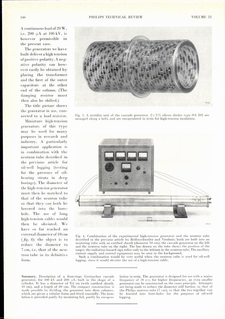
Fig. 3. A rectifier unit of the cascade generator. 2 X 175 silicon diodes type OA 202 arearranged along a helix and are encapsulated in resin for high-tension insulation.
7420
Fig. 4. Combination of the experimental high-tension generator and the neutron tubedescribed in the previous article by Heifenschweiler and Nienhuis; both are built into aninsulating tube with an earthed sheath (diameter 10 cm), the cascade generator on the leftand the neutron tube on the right. The line drawn on the tube shows the position of thetarget; the radiation-hazard sign refers only to the tritium in the neutron tube. The ancillarycurrent supply and control equipment may be seen in the background.
Such a combination would be very useful when the neutron tube is used for oil-welllogging, since it would obviate the use of a high-terision cable.
Summary. Descriptiou of a four-stage Greinacher cascadegenerator, for 100 kV and 200 [LA, built in the shape of acylinder. It has a diameter of 9.6 cm (with earthed sheath.10 cm), and a length of 80 cm. The compact construction ismade possible by dividing the generator into three columns.which are given a tubular form and fitted coaxially. The insn-lation is provided partly by insulating foil, partly by cncapsu-
lation in resin. The generator is designed for use with a mainsfrequency of 50 cis; for higher frequencies, an even smallergenerator can be constructed on the same principle. Attemptsare being made to reduce the diameter still further, to that ofthe Philips neutron tube (7 cm), so that the two together canbe lowered in to bore-holes Ior the purposes of oil-welllogging.

1961/62, No. 11
ADJUSTING THE ION BEAM IN A PARTICLE ACCELERATOR
In nuclear research "large" accelerators are used, such ascyclotrons and synchrocyclotrons, and also various "srnall "types, capable of accelerating particles up to an energy of1 MeV. In these small accelerators the target section, whichshould be readily accessible, is usually located in a room belowthat corrtairring the high-tension generator. The photographshows the target section of an accelerator of this kind (cascadegenerator in a pressure tank), made by Philips for an instituteof nuclear physics. If the ions are accelerated with a relativelylow voltage, it is permissible to remain near the target, and theluminous beam of ions can then be seen through a glass insu-lator. By introducing into the beam a quartz plate attached toa spindle, as is being done here, the area struck by the beam isbrilliantly illuminated. The target can then be accuratelypositioned with respect to the ion beam by means of four
Photo Maurice Broomfield
adjusting screws (three of which are visible on the photograph).A vacuum lock above the adjustable target section makes itpossible to admit air into this section and to change the targetwhilst maintaining the vacuum in the accelerator itself.
The simple water-cooled target shown here, which serves formeasuring the target current, can be replaced by, for example,a rotating target of heavy ice, cooled with liquid air. Whenbombarded with deuterons of 800 keY this target is able todeliver up to 1010 neutrons per second 1), produced by thereaction D( d,n)3He.
1) A. C. van Dorsten and J. H. Spaa, A high-output D-Dneutron generator for biological research, Nucl. Instr. 1,259-267,1957.
341