An Experimental and Analytical Evaluation of the … Technical Memorandum 101 049 ' An Experimental...
18
NASA Technical Memorandum 101 049 ' An Experimental and Analytical Evaluation of the Tapered Tension-Torsion Strap Concept Alexander Louie (bASA-TB-lUlCU9) AN ErEEfilbE&1AL AliD- - dbALY?'ICAL EYALCA%IGI OF I&€ lA€ERED I€LSlCY-ICBZICU SllRAF CCYCEtl (rASA) 78 p - 189- I3746 CSCL 20D Unclas G3/34 dl17652 November 1988 NASA National Aeronautics and Space Administration https://ntrs.nasa.gov/search.jsp?R=19890004375 2018-07-02T15:13:39+00:00Z
Transcript of An Experimental and Analytical Evaluation of the … Technical Memorandum 101 049 ' An Experimental...

NASA Technical Memorandum 101 049 '
An Experimental and Analytical Evaluation of the Tapered Tension-Torsion Strap Concept Alexander Louie
(bASA-TB-lUlCU9) A N E r E E f i l b E & 1 A L AliD- -
dbALY?'ICAL EYALCA%IGI OF I & € l A € E R E D I € L S l C Y - I C B Z I C U Sl lRAF C C Y C E t l ( r A S A ) 78 p
- 189- I3746
CSCL 20D Unclas G3/34 dl17652
November 1988
NASA National Aeronautics and Space Administration
https://ntrs.nasa.gov/search.jsp?R=19890004375 2018-07-02T15:13:39+00:00Z

NASA Technical Memorandum 101 049
An Experimental and Analytical Evaluation of the Tapered Tens i o n-To rs i o n Strap Concept Alexander Louie, Ames Research Center, Moffett Field, California
November 1988
NASA National Aeronautics and Space Administration
AmesResewchcenter Moff ett Feu, c a l i i 94035

SUMMARY
A new free-tip rotor moment controller designed to increase torque output (a restoring moment) was proposed. The controller would be used as a retention device for the freely pitching tip of a helicopter rotor. The new design featured a tapered tension-torsion strap instead of the previously used parallel strap. A tapered strap has a larger separation between the tension wires at the retention end than at the oscillating end; separation is equal at both ends for a parallel strap.
A simple dynamic analysis was developed and an experiment was performed to evaluate this tapered strap concept. The test results indicated that the torsional spring stiffness of the strap, represented by a torsional pendulum, increased with the amount of taper. The predicted dynamic characteristics of the pen- dulum also confirmed this observation and correlated reasonably well with the experimental results. It could be concluded from the experimental and analytical results that the tapered strap accomplished increased torque output when it was compared with a parallel strap. This report documents the results of the investigation.
INTRODUCTION
Two major objectives in helicopter rotor technology research arc perfomce improvement and vibra- tion reduction. The free-tip rotor concept (figs. 1 and 2), proposed and investigated by Stroub (ref. l), has shown considerable promise in achieving these two goals. This type of rotor differs from conven- tional rotors by a free pitching tip at the outermost portion of each rotor blade, with a pitch axis forward of the blade's aerodynamic center. For a conventional rotor, the aerodynamic forces on the tip vary around the azimuth. The free tip, however, responds to the changing aerodynamic forces by continually changing its angle of attack to maintain moment balance about the pitch axis. In order to balance the inertial moment of the tip and the near constant moment applied by a moment controller, the resulting aerodynamic moment must also be constant at different azimuthal stations. That is, the tip achieves its equilibrium by weathervaning into its relative wind to produce a near uniform lift force. This tip characteristic contributes to the improvement of rotor performance and the alleviation of oscillatory blade dynamic air loads.
The moment controller mentioned above is a passive mechanical device that produces a preset torque. As the free tip travels around the azimuth, the aerodynamic forces and the controller act like a spring to adjust the perturbed tip to a new equilibrium position. Ideally, a constant moment generated by the con- troller is desirable because it would produce a constant tip lift. This cannot be achieved because any changes in the free-tip angle of attack affect the torque output of the controller. However, an optimum condition can be attained by making the preset controller moment very large in comparison with the aero- dynamic moment variation resulting from changes in angle of attack of the tip, thereby generating a near- constant tip lift. Since the moment controller is responsible for regulating the tip lift, it is a critical compo- nent in the free-tip rotor concept.
1

A number of prototypes for the moment controller were investigated by Young (ref. 2). Besides a maximum toque output, the main critexion for the final design selection was a low torsion spring stiff- ness, which was required to ensure that the free tip decoupled from the inboard blade torsionally. In other words, the free tip would then be able to respond better to changes in aerodynamic forces. After the pro- totypes were evaluated, a tension-torsion strap design (fig. 3) was selected as the controller far the free-tip rotor model documented in reference 1.
The tension-torsion strap design evaluated in reference 2 was composed of thin wires wound into par- allel straps which were embedded in an elastomeric filler. The torsional moment is mainly derived from a component of the tensile load in the wires. One can picture how this strap functions by envisioning a tor- sional pendulum. When the pendulum is turned, tension in the suspension wires is no longer aligned with the direction of the pendulum's weight, thus producing a force couple. Once the twist is released, these tension force components produce a restoring moment about the pendulum's centerline to rotate it toward its rest position. The tension-torsion strap operates in an analogous manner, except that the strap's tensile load is due to the centrifugal farce on the free tip instead of to the weight of the pendulum.
After the wind tunnel test documented in reference 1, it was suggested that the frce-tip rotor perfor- mance might be further improved by increased tip lift. In order to achieve this, a larger toque from the moment controller would be r e q u i d to counteract the aerodynamic moment. Meanwhile, any transient torsional oscillation of the tip about its pitching axis would still have to be miNmizcd to produce a rela- tively constant lift. In meeting these new requirements, a tapered tension-torsion strap design is sug- gested. Instead of being parallel, the separation between the strap wires of this design varies linearly such that it is larger at the inboard end than at the tip junction (fig. 3).
A torsional pendulum experiment was conducted to demonstrate that a tapered tension-torsion strap configuration would produce a higher maximum torque output than a parallel one. The description of the test setup is included in the next section. A mathematical model for the pendulum is fmulated to investi- gate the system's dynamic characteristics. The analytical and experimental results are correlated in this report. Finally, some design considerations regarding the tapered tension-torsion strap as applied to the free-tip rotor are discussed. A list of the symbols used in this report follows.
SYMBOLS
separation of suspension wircs at oscillating end
separation of suspension wires at futed end (d2 > dl)
fame vector in ith wire in the rotating plane
gravitational acceleration
unit vectors with origin located at the top center of steel bar
mass moment of inertia about the pendulum's centerline
torsional spring stiffness
2

vertical length of the pendulum
mass ofpendulum
moment arm from centerline to irh wire
tension in one suspension wire
horizontal component of the wire tension
torsional displacement
angular acceleration
torsional displacement at nth oscillation
initial torsional displacement
averaged logarithmic decrement for three oscillations
logarithmic decrement at nrh oscillation
one-half the angle formed by the suspension wires (also referred to as taper angle)
average period
angular displacement of wires projected on horizontal plane
undamped natural torsional frequency
damped natural torsional frequency
experimental damping coefficient
Note: All prime notation denotes experimental results.
EXPERIMENTAL SETUP
A simple torsional pendulum was used to study torque output of both the parallel and the tapered tension-torsion strap. If the suspension wires were set parallel, the system became a bifilar pendulum representing a conventional strap. Otherwise, it simulated a tapered strap when the suspension wires f o d a V-shape. This experiment was intended to demonstrate that the toque produced by the tension- torsion strap varied proportionally with the width of the strap's fixed end (di), or in effect, the taper angle (e). To achieve this objective, it was necessary to show that the maximum restoring moment of the pen- dulum increased with d2 for a fixed angular deflection. But since the restoring moment of the pendulum can be approximated by M = k,a (a linear spring), it is sufficient to prove the concept by establishing the relationship between k, and dz
3

The experimental setup consisted of a rectangular steel bar suspended on two 0.66-mm-diameter nylon wires. The steel bar weighed 5.21 kg with a mass moment of inertia about its centerline of 0.00126 kgSm2. The t a p angle was adjusted by anchoring the wires to different sets of holes in the supporting plate. The vertical distance 1 between the fixed and free end was maintained at 0.26 m. The separation dl between the two wires at the oscillating end was 15.9 mm. The ends of the wires were clamped to resmct motion to torsional oscillation. A pointer at the bottom of the pendulum was used to identify the amplitude (a) and the period ('t) of each cycle. During each run, the pendulum was rotated approximately 300 aid then released. As it oscillated about the rest position, the amplitudes for three cycles were marked and the elapsed time for 10 periods was measured (using a hand-held stop watch).
Two wires were used to simplify the experimental setup and to minimize the uncertainties, such as uneven distribution of tensile load and interference among wires. If a set of wires is used, each wire should ideally carry an equal load and should rotate by the same angle. After superposition of forces on individual wires, the wire set can then be represented by two wires. Thus the dynamic analysis with two wires can be extended to a collection of wires, which is the case of the tension-torsion strap.
.
MODELING OF THE TORSION PENDULUM
I The dynamic characteristics of the torsion pendulum used in the experiment were also investigated analytically. The following assumptions wcrc made:
1. The system's response to twisting was considered to be purely torsional motion
2. The torsional spring was linear
3. The wires did not elongate under the tensile load
4. The material of the suspension wires was considered to be isotropic with homogeneous properties
5 . The torsion stiffness of the wire was negligible
~
6. The reduction in vertical length of wires, as a result of twist, was not accounted for
With these assumptions, and if all damping effects are neglected, the moment equation in the vertical direction is sufficient to describe the dynamics of the system:
r l x F 1 + r2x F, = I & k
where the subscripts refer to wires 1 and 2, respectively. The reference coordinate is fixed with its origin located at the free end of the pendulum (top center of the steel bar). For the case of the tension-torsion strap applied to a free tip, the angular deflection would be the incidence angle of the tip relative to the inboard blade at the tip junction. In equation (l), di would then correspond to the pitch acceleration of the free tip.
From figure 4 it can be Seen that the moment arm is the distance between the pendulum centerline and one of the wires at the oscillating end,
4

dl r = 2 (cos a i + s i n a j )
In the present case only the forces in the horizontal plane arc need&
F = TXy(cos $ i + sin$ j )
where Txy is the horizontal component of the wire tension T. Since the small vemcal displacement of the steel bar during the torsional oscillation shown in figure 4 is neglected, the taper angle 8 is essentially constant, and
T, = T sin $
Also, from the geometry shown in figure 4,
sin dl a
1 me sin $ =
dl - cosa d2 - - 2 2
Itan0 cos $ =
Substituting equations (4) through (6) into equation (3), the resultant force becomes
mg F = x [ ( d 2 - d l c o s a ) i - d l s i n a j] (7)
By applying the above results to equation (1) and recognizing the symmetry of the pendulum system, the equation of motion reduces to
I a + m g d d a=O 41 1 2
Note that this equation is simplified with a small angle approximation in a (i. e., cosa = 1, sina = a). The above dif€cxential equation has the form of a mass-spring system that gives
mg =-d d k t 41 1 2
where o, is the natural frequency and kt is the torsion spring stiffness.
5

Then, for a fixed cc, it can be deduced from equation (10) that the torque output of the tension-torsion strap is only a function of the length and width of the strap. Note that when dl = d2, equations (7) through (10) reduce exactly to those far a bifilar pendulum.
REDUCTION OF EXPERIMENTAL DATA
The methods used in the experimental data reduction are presented below. After viscous damping of the system is estimated, the undamped natural frequency is calculated and compared with theoretical val- ues. As in the above mathematical model, this experimentally determined frequency is also considered to be purely torsional.
The damped natural frequency of an oscillating system is calculated by
2R O n d - 5,
--
where z,, is the averaged period over 10 cycles. The undamped natural frequency is
I OLd '
(12)
0, =
where 6 is the damping coefficient. Note that the torsional spring stiffness is k,' = ~ , ' 2 I. By using the logarithmic decrement method shown in figure 5,
for the nrh cycle, then the overall damping coefficient becomes
where 6,, is the averaged logarithmic decrement over the first three cycles.
CORRELATION OF ANALYTICAL AND EXPERIMENTAL RESULTS
The torsion spring stiffness and natural frequency calculated from the experimental data using equa- tions (1 l) to (14) are presented in figures 6 and 7. Meanwhile, their correlations with the analytical solution are also shown. From these figures, it can be concluded that by increasing the fixed end separation (dd, the spring rate (and consequently the restoring moment), of the pendulum also increases linearly. For the range of d2 being tested, the magnitudes of the damping coefficient (maximum 0.06)
6

and the damped natural frequency (maximum 8 rad/sec) arc very small. It can be determined from equation (14) that the damping effect on the undamped natural frequency is negligible.
Recall that both the dynamic analysis and the data reduction were simplified by considering only tor- sional motion and neglecting the translational pendulum motion. This was a fairly good approximation for small strap taper angles (i. e., d2 < 48 mm). But in the experiment, as d2 increased, the amount of translational pendulum motion (sideward swing) of the steel bar that was neglected also grew. This might be caused by some uncontrollable translational displacement of the steel bar when it was twisted initially. It might also be due to a stronger tendency for the pendulum to move laterally upon perturbation as the component of the tension not aligning with the axis of rotation increased. As a result, part of the system's kinetic energy was transferred from torsion to other types of motion and the restoring moment was reduced. The experimental torsion spring stiffness would then be lower than the theoretical values. As confmed by figure 6, the test data deviated more significantly from the analytical solutions with increased wire separation (high values of e). Nevertheless, the experimental data still exhibited the linear behavior of the torsional spring.
For most test runs, there were nonzero angular displacements of approximately 100 when the pendu- lum was at rest. This might be due to the uneven wire lengths, existing twist, or nonisotropic properties of the wires. Moreover, the maximum amplitude of oscillation (a) in the test somctimcs reached as high as 400 to avoid the damping out of oscillations before the period could be measured accurately. At high values of a, of course, the small angle approximation used in simplifying the equation of motion was not valid.
Despite the fact that these discrepancies violated the previously stated assumptions, they were not accounted for in the data reduction and the dynamic analysis because their effects were observed to be small. Additionally, the measured amplitudes of oscillation about the rest position were very close to the analytical prediction. Therefore the resulting experimental natural frequencies should be accurate enough for comparison with theoretical values. The analytical prediction indeed agreed well with the experimental data.
OTHER DESIGN CONSIDERATIONS
From the above discussion, the validity of the concept that torque output increases with the taper of the tension-torsion strap has been established. But the= are additional design constraints that need to be con- sidered before the tapered tension-torsion strap can be implemented in the free-tip moment controller design.
Examining equation (9) reveals that as the width (dz) increases or as the length 0) decreases, the torsion spring stiffness will increase without bound. This seems to suggest that a tension-torsion strap can be designed to produce as high a torque output as desired. But in reality the mechanical properties of the strap will limit the system's torsional spring stiffness. Three primary constraints-the tensile and torsional stress in the wires and the physical dimensions of the controller-are discussed below.
As the length of strap I decreases, the twist per unit length, War, increases for the same angular displacement at the outboard end of the strap ( a w e pitch angle of the free tip. If a&& is too large, the elastomeric filler may first be damaged by extreme amounts of twisting. Then, the torsional stress and other secondary loads may increase so much that they ex& the yield or fatigue strength of the wires.
7

When inmasing the t a p angle, the tension in the wires also increases rapidly according to T = FJcos 8. A small change in 8 can result in a large increment in T because of the high centrifugal force, Fc, generated by the free tip of a full-size rotor at operating speed. Thus the tensile stress may become a critical design constraint. Additionally, the large alternating loads can considerably shorten the fatigue life of the strap. Since the strap wires would be tapered instead of parallel, the geometry of the strap under deformation must be investigated. The problem to be addressed is the possibility of interfer- ence between the strap and its housing cavity.
A tapered tension-torsion strap design suitable for the &-tip mor application must be composed of wires embedded in a tapered elastomeric filler. For the present design, the cross sections of the filler are rectangular. The filler's deformation under twisting is very Micult to analyze. Some simplifications are used in the following preliminary study. The wires in tension can be thought of as rigid rods for the kinematic analysis. When a torsional moment is applied, the wires ate rotated about the centerhe of the strap. This in effect is assuming a linear twist distribution along the strap length. If this approximation is further applied to the elastomeric filler, the surfaces and the cross sections of the filler will remain planar under torsion. It can be shown that the strap will not interfere with the cavity wall as long as the height of the wall is greater than the diagonal length of the strap's cross section at the free end.
For a preliminary investigation, the above argument may suffke. But in reality, the IilleI's rectangular cross sections and surfaces under torsion will warp out of their original planes. By visual inspection of a tapered rubber bar under twisting, it appears that contact between the strap and the cavity wall, if @ere is any, occurs near the fixed end. This observation indicates the linear twist approximation is not too badly in e m , and therefore is conditionally acceptable. Otherwise, in d e r to compute the exact clearance between the strap and cavity, more vigorous shuctural analysis will be required to study the filler's defor- mation under twisting.
CONCLUSION
It can be concluded from the results of a torsion pendulum test and its mathematical model that a tapered tension-torsion strap can produce a higher torque output than its parallel counterpart. The reason for this is that as the amount of taper increases, so docs the component of tension in the plane of rotation. This results in a larger restoring moment repsented by a stiffer torsional spring. Thus a tapered tension- torsion strap is favored over a parallel design for the &-tip rotor moment controller in generating higher tip l i t to increase the rotor perfarmance. But it should be noted that there may be penalties to the increased stiffness of the tapered tension-torsion strap that have not been addressed in this report. For example, an increase of the torsional spring stiffhess implies that the new frec tip will oscillate more than the previous model. Finally, the design constraints discussed before must be addressed before incorporating the new controller concept into a free- tip rotor.
8
REFERENCE
1. Stroub, Robert H.: Analysis of the Free-Tip Rotor Wind-Tunnel Test Results. NASA TM 86751, 1985.
2. Young, Lany A.: The Evaluation of a Number of Prototypes for the Free-Tip Rotor Constant-Moment Controller.. NASA TM 86664, 1986.
9

PITCH AXIS AND CENTER OF GRAVITY
CONTROL 1 MOMENT, M, SELF ADJUSTING
BLADE PITCH
Figure 1.- Schematic of the free tip.
10
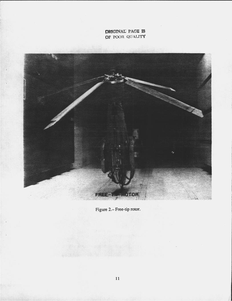
Figure 2.- Free-tip rotor.
11

PARALLEL TENSION-TORSION STRAP
CF
TAPERED TENSION-TORSION STRAP
> \
7 OSCILLATING
END / I-Q FIXED I END
TAPERED TENSION-TORSION STRAP PLANFORM VIEW
Figure 3.- Schematic of the parallel and tapered tension-torsion strap.
12

I -w TOP VIEW
BEFORE TWIST AFTER TWIST
I Q I
BEFORE TWIST AFTER TWIST
/
I Q I
/ ~ /
/
I
1 , J FRONT VIEW L--- .-L-
Figure 4.- Top and front view of the torsional pendulum.
13

k + n
Figure 5.- Determination of damping coefficient by logarithmic decrement method
14

.150
-125
.loo E 2 .075 0 \
t Y
.050
.025
- VALUES CALCULATED BY EQ. 10
- -
-
-
-
-
0 EXPERIMENTAL DATA
PARALLEL STRAP
15.0
12.5
10.0
H 3 7.5
t 5.0
2.5
I I I I I I 0 25 50 75 100 125 150
. d2mm
- - VALUES CALCULATED BY EQ. 9
- 0 EXPERIMENTAL DATA
-
-
-
- PARALLEL STRAP
Figure 6.- Torsional spring stiffness of the torsional pendulum.
0 25 50 75 100 125 150 d2, mm
Figure 7.- Natural frequency of the totsional pendulum.

I .
1. Report No.
NASA TM-101049 2. G w n m a n t Accruion No. 3. Recipient’s Catalog No.
An Experimental and Analytical Evaluation of the Tapered Tension-Torsional Strap Concept
4. T i and Subtitb 5. Report Date
National Aeronautics and Space Administration Washington, DC 20546-0001
7. Author(rJ
Alexander Louie
9. Performing Organization Name and Addresa Ames Research Center Moffett Field, CA 94035
2. SponrorinO Agency Naw .nd Addreas
14. Sponsoring Agency Code I
8. Performing Organization Report No.
A-8832 1 10. work UnH No.
505-61-51
11. Contract or Grant No.
13. Type of Report and Pwiod Covered
Technical Memorandum
I 5. Suppkmmtary Not-
1. Key Wordr (Suggested by Author(rH
Free-tip rotor Moment controller Tapered tension-torsion strap
Point of Contact: Alexander Louie, Ames Research Center, MS TO31 Moffett Field, CA 94035 (415) 694-6976 or FTS 464-6976
18. Dirtribution Statement
Unclassified-Unlimited
Subject Category - 01
6. Abstract
20. Security ClOUif. (of thir page) 21. No. of page8 #. Security Clauif. (of the report),
Unclassified Unclassified 18 22. Price
A02