Experimental investigation of the softening–stiffening ...

An Experiment on Tension Stiffening Effects of High Strength
Concrete
Jee-Sang Kim, and Chan Hyuk Park Seokyeong University, Civil and Architectural Engineering Department, Republic of Korea
e-mail: [email protected] / [email protected]
Abstract: The verification of serviceability of concrete structures such as crack widths, crack spacings and
deformations requires more information on the composite behaviors between concrete and reinforcements.
Among them, the investigation of crack widths and spacings is based on the tension stiffening effects. In this
paper, the tension stiffening effect of high strength concrete members with compressive strength of 80 and
100MPa reinforced by D13 are investigated experimentally. The experimental results of this study revealed that
the tension stiffening effects of smaller diameter reinforcement (D13) is more distinct than those in larger
diameter reinforcement (D10). The reduction of tension stiffening effects in high strength concrete disappears for
smaller diameter reinforcement. A modified tension stiffening factor that can be used for high strength concrete
is proposed based on experimental results.
Keywords: Tension stiffening, high strength concrete, tensile member, cover thickness.
1. Introduction
Researches on the high strength and high performance of concrete is actively being carried out and
application examples are also increasing. As the strength and performance of the concrete have been improved,
it is possible to reduce the sectional dimensions and the total weight of the structure. Generally, when designing
a reinforced concrete member, the role of concrete in the tensile region is usually ignored and only the
equilibrium condition of force is mainly considered. However, from the viewpoint of macroscopic scale, it is
increasingly necessary to consider not only the equilibrium condition of force but also the deformation
compatibility.
When crack occurs in a concrete tensile member reinforced with reinforcing bars, the stress is redistributed
on the crack face due to the difference in rigidity of the two materials. In the cracked section, the reinforcing
bars are responsible for all the tensile forces due to the applied load. However, as the load is increased, the
cracks are continuously formed, and the concrete between the cracked ends will bear part of the tensile force
transmitted from the reinforcing bars by adhesion. The tension stiffening effect is a phenomenon in which the
stiffness of reinforcing bars increases or the strain or stress decreases due to the contribution of concrete between
cracks [1]. It is an important factor in evaluating the performance of the concrete that will bear the tensile force
between the cracked sections, such as crack widths and deflections, affecting the stiffness and effective
secondary moment of inertia [2].
The purpose of this study is to understand the tension stiffening effects when applied to high strength
concrete. Direct tensile tests were carried out with the thickness of cover and the strength of concrete as
variables. Using the experimental results obtained in this study, the tension stiffening effect was determined by
the cover thickness and by the strength of concrete, and the tensile reinforcement coefficient was corrected.
ISBN 978-93-84422-76-9
International Conference on Research & Innovation in Environment, Civil and Architecture Engineering
(RIECAE-17)
Bangkok (Thailand), Feb. 6-7, 2017
https://doi.org/10.17758/EIRAI.F0217315 115

2. Theoretical Backgrounds
Fig. 1 Load-Strain Relation of Tensile Specimen [3]
In a cracked cross section, all tensile forces are balanced by steel only. However, between adjacent cracks,
tensile forces are transmitted from the steel to surrounding concrete by bond stress. The contribution of concrete
may be considered to increase the stiffness of tensile reinforcement, which is called tension stiffening as shown
in Fig.1. If the tension stiffening effect is neglected, the stiffness of a reinforced concrete bar or a structural
member is underestimated. It is defined as the mean strain function of the reinforcing bars shown in Fig. 1 based
on the direct tensile test results. When calculating the tension stiffening effect in this way, distinction should be
made between the crack formation stage and stabilized cracking stage.
(a) uncracked
1ssm (1)
(b) crack formation stage
)()()(
12
1
12 ssr
srsrn
ssrnsrstssm
(2)
(c) stabilized cracking stage
)( 122 sesrtssm (3)
(d) post-yielding
where, 1s is the strain of reinforcement in uncracked concrete,
2s is the strain of reinforcement in the crack,
1sr is the strain of reinforcement of zero slip under cracking forces reaching )(tfctm , 2sr is the strain of
reinforcement at the crack under cracking forces reaching )(tfctm ; if the internal forces are lower than or equal to
the cracking forces (e.g. in a working joint), sy is the strain at yield strength,
s is the steel stress in the crack,
1sr is the steel in the crack, when first crack has formed, srn is the steel stress in the crack, when stabilized
crack pattern has formed(last crack). Also, 4.0t for short-term loading (pure tension), 25.0t for long-
term or repeated loading (pure tension). Here, the concept of mean strain sm of steel bars is defined by the
method as follows in the crack stabilization stage after cracking occurs [1]. To simplify this
s
cttsosm E
f (4)
Equation (4) is a simplified expression based on the results of experimental results [4]. The relation includes
the effect of the cover thickness and concrete compressive strength on the tension stiffening effect but not the
splitting cracks.
As a result of the experimental study, the tension strengthening effect decreases when splitting cracks occur
in tensile members [5],[6]. The effect of splitting cracks should be considered when the c/db of tensile members
https://doi.org/10.17758/EIRAI.F0217315 116

is less than 2.5. The results of the study on the tension stiffening effect of the high strength concrete showed that
it decreased as the strength of concrete increased [2].
3. Experiments
The test specimens in this study were axially loaded direct tension members with a length of 700mm,
containing single 13mm bars of yield stress 420 MPa at the centers of specimens. The cross-sectional area of the
specimen was kept constant of 10000 mm2 in all specimens to consider the ratio of cover thickness to the bar
diameter (c/db) between 1.5 and 3.5 in 0.5 increments. The compressive strength of the concrete was set to
80MPa and 100MPa. According to the level of the target strength, the types of the concrete was SC80(80Mpa),
and SC100(100Mpa), and the compressive strength test results were measured as fc = 82.4Mpa for SC80 and fc =
103.5Mpa for SC100, and the required compressive strength was obtained by a standard test with cylinder of a
diameter 100 mm and a height of 200 mm. The concrete mix design is shown in Table I.
TABLE I: Mixture Design of Concrete(Kg/m3)
Constituents SC 80 SC 100
W/B (%) 0.225 0.2
S/A (%) 0.42 0.42
W 150 165
OPC 466 577
BS 133 165
FA 66.7 0
Sand 647 570
Agg 898 792
SP 6.667 18.15
Fig. 2 Test settings
A displacement control method was employed and the longitudinal elongation between the each of specimen
was measured as in Fig.1, with two LVDTs mounted at each corner. The load - strain relationship was
investigated by measuring the strain of the steel and using the mean value. The cracks observed during the
loading were marked and used in investigating the overall cracking behaviour.
4. Results and discussions
4.1. Tension stiffening effects To examine the influence of the ratio of cover thickness to the bar diameter, the load-strain relation
measured in the experiment is summarized in Fig. 3 and compared with the current design standard MC 2010[3]
for the compressive strength of SC 80. Three specimens were fabricated for various ratios of cover thickness to
the bar diameter (c/db) of 80 MPa and representative values were obtained. A total of 15 specimens were
fabricated for each 5 cover thickness ratios, 1.5,2, 2.5, 3 and 3.5. When ratio of cover thickness to the bar
https://doi.org/10.17758/EIRAI.F0217315 117

diameter (c/db) is relatively low, 1.5 and 2, splitting crack occurs first like conventional normal concrete, even
though the concrete strength is increased to 80 MPa. On the other hand, in the case of the member having 2.5c/db
or more of which the ratio of the cover thickness to the bar diameter (c/db) which were sufficiently secured, the
value exceeding MC 2010 were obtained. This suggests that it is necessary to modify the tensile enhancement
coefficient which is improved as the cover thickness is changed.
(a) SC80-1.5c/db
(b) SC80-2c/db
(c) SC80-2.5c/db
(d) SC80-3c/db
(e) SC80-3.5c/db
Fig. 3 Load-average steel strain relations for SC80
https://doi.org/10.17758/EIRAI.F0217315 118
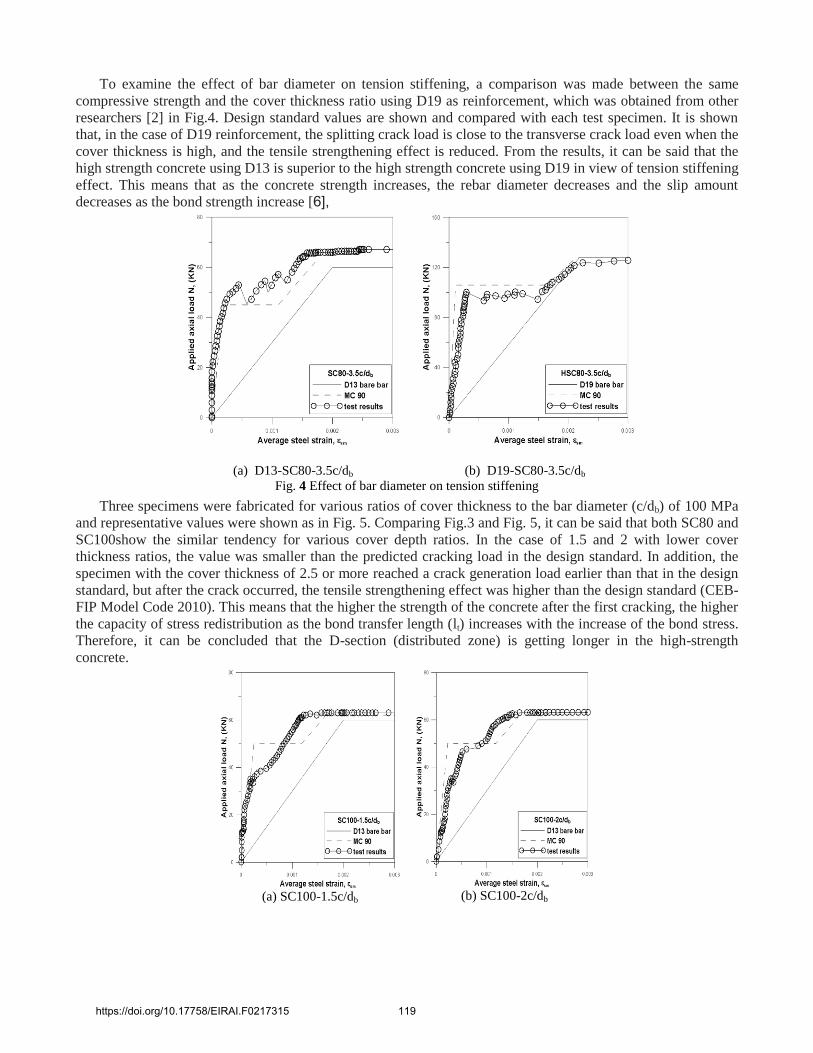
To examine the effect of bar diameter on tension stiffening, a comparison was made between the same
compressive strength and the cover thickness ratio using D19 as reinforcement, which was obtained from other
researchers [2] in Fig.4. Design standard values are shown and compared with each test specimen. It is shown
that, in the case of D19 reinforcement, the splitting crack load is close to the transverse crack load even when the
cover thickness is high, and the tensile strengthening effect is reduced. From the results, it can be said that the
high strength concrete using D13 is superior to the high strength concrete using D19 in view of tension stiffening
effect. This means that as the concrete strength increases, the rebar diameter decreases and the slip amount
decreases as the bond strength increase [6],
(a) D13-SC80-3.5c/db (b) D19-SC80-3.5c/db
Fig. 4 Effect of bar diameter on tension stiffening
Three specimens were fabricated for various ratios of cover thickness to the bar diameter (c/db) of 100 MPa
and representative values were shown as in Fig. 5. Comparing Fig.3 and Fig. 5, it can be said that both SC80 and
SC100show the similar tendency for various cover depth ratios. In the case of 1.5 and 2 with lower cover
thickness ratios, the value was smaller than the predicted cracking load in the design standard. In addition, the
specimen with the cover thickness of 2.5 or more reached a crack generation load earlier than that in the design
standard, but after the crack occurred, the tensile strengthening effect was higher than the design standard (CEB-
FIP Model Code 2010). This means that the higher the strength of the concrete after the first cracking, the higher
the capacity of stress redistribution as the bond transfer length (lt) increases with the increase of the bond stress.
Therefore, it can be concluded that the D-section (distributed zone) is getting longer in the high-strength
concrete.
(a) SC100-1.5c/db (b) SC100-2c/db
https://doi.org/10.17758/EIRAI.F0217315 119

(c) SC100-2.5c/db (d) SC100-3c/db
(e) SC100-3.5c/db
Fig. 5 Load-average steel strain relations for SC100
4.2. Crack Generation Load Comparison The crack resistance of high - strength concrete was verified by comparing crack generation load of
specimen of normal strength concrete (fc = 30MPa) using D13 reinforcing steel and crack generation load of high
strength concrete (SC80). The effect of splitting crack, which is a factor that inhibits the tension stiffening effect,
was confirmed by this study. In addition, the predicted transverse cracking loads with various compressive
strengths were compared.
TABLE II: Comparison of Transverse Cracking Load Ntr
c/db Transverse cracking load Ntr (KN)
NC 30 SC 80
1.5 - 34
2 14 37
2.5 19 42.5
3 17 47
3.5 24 46
Table II compares the crack initiation loads of normal and high strength concrete through the experimental
results. Table III compares the predicted transverse cracking loading with the actual measured transverse
cracking loading according to compressive strength. For NC 30, the expected transverse crack initiation loads
are N30 = 28KN and for SC 80 the expected crack N80 = 45KN. The actual lateral crack initiation load according
to the cover thickness for the predicted transverse crack occurrence load is shown in Fig. 6
TABLE III: Comparison of Transverse Cracking Load Ratio
c/db Transverse cracking load ratio
NC 30 SC 80
1.5 - 0.75
2 0.5 0.82
2.5 0.68 0.98
3 0.61 1.04
3.5 0.85 1.02
https://doi.org/10.17758/EIRAI.F0217315 120
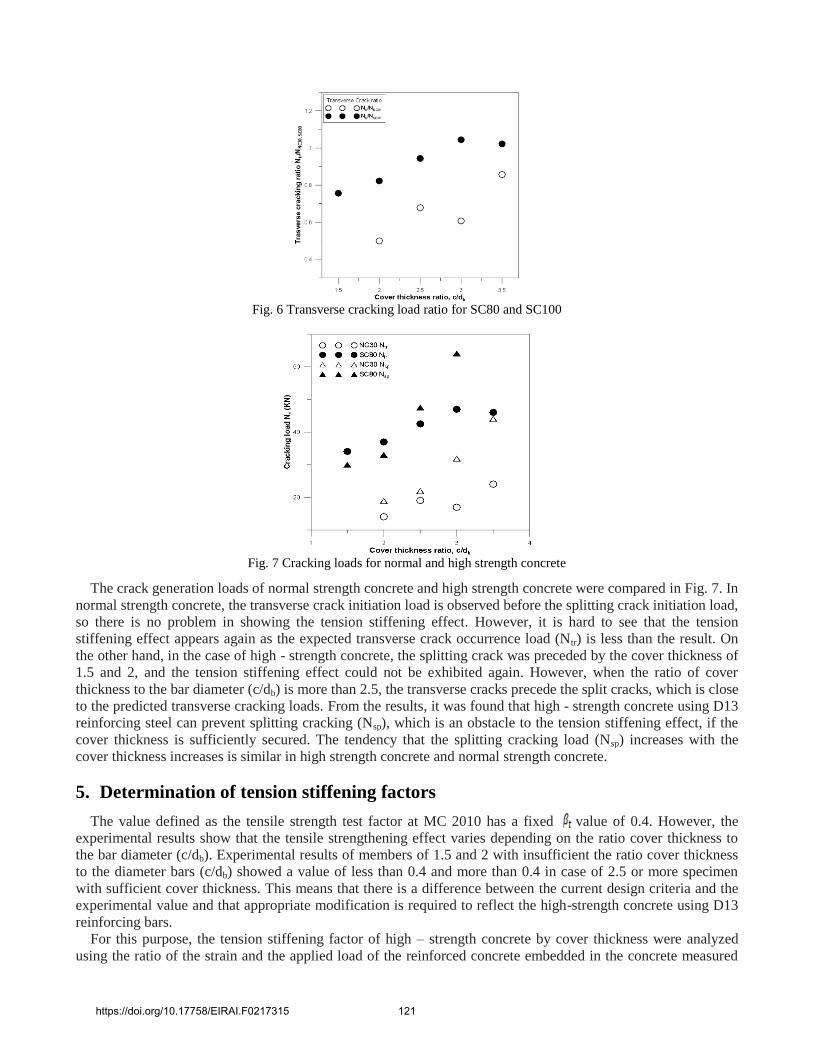
Fig. 6 Transverse cracking load ratio for SC80 and SC100
Fig. 7 Cracking loads for normal and high strength concrete
The crack generation loads of normal strength concrete and high strength concrete were compared in Fig. 7. In
normal strength concrete, the transverse crack initiation load is observed before the splitting crack initiation load,
so there is no problem in showing the tension stiffening effect. However, it is hard to see that the tension
stiffening effect appears again as the expected transverse crack occurrence load (Ntr) is less than the result. On
the other hand, in the case of high - strength concrete, the splitting crack was preceded by the cover thickness of
1.5 and 2, and the tension stiffening effect could not be exhibited again. However, when the ratio of cover
thickness to the bar diameter (c/db) is more than 2.5, the transverse cracks precede the split cracks, which is close
to the predicted transverse cracking loads. From the results, it was found that high - strength concrete using D13
reinforcing steel can prevent splitting cracking (Nsp), which is an obstacle to the tension stiffening effect, if the
cover thickness is sufficiently secured. The tendency that the splitting cracking load (Nsp) increases with the
cover thickness increases is similar in high strength concrete and normal strength concrete.
5. Determination of tension stiffening factors
The value defined as the tensile strength test factor at MC 2010 has a fixed value of 0.4. However, the
experimental results show that the tensile strengthening effect varies depending on the ratio cover thickness to
the bar diameter (c/db). Experimental results of members of 1.5 and 2 with insufficient the ratio cover thickness
to the diameter bars (c/db) showed a value of less than 0.4 and more than 0.4 in case of 2.5 or more specimen
with sufficient cover thickness. This means that there is a difference between the current design criteria and the
experimental value and that appropriate modification is required to reflect the high-strength concrete using D13
reinforcing bars.
For this purpose, the tension stiffening factor of high – strength concrete by cover thickness were analyzed
using the ratio of the strain and the applied load of the reinforced concrete embedded in the concrete measured
https://doi.org/10.17758/EIRAI.F0217315 121

through direct tensile test of high - strength concrete. For this purpose, the coefficient of the CEB-FIP Model
Code 2010 [3], which specifies the tension stiffening effect, was verified and the influence of the cover thickness
was examined. The time when the first crack occurred for the various cover thicknesses was determined, and the
tension stiffness coefficient calculated from the crack load to the rebar yield strength was calculated by the
arithmetic average of the tensile stiffness coefficients according to the increase of the working load. As an
example, the value of SC80 cover thickness (c/db) is 3.5, as shown in Fig. 7
)(ct
ssmsot f
E (5)
Fig. 8 Comparison of design criteria and tension stiffening factor,
Regarding these values, the regression analysis was performed for varying ratios of the cover thickness to
the rebar diameter, and the tensile reinforcement coefficient formula, which can be applied to the linear tension
stiffening effect model according to the MC 2010, was obtained as follows.
5.0)4.2
/(4.0 b
t
dc (6)
The coefficient of determination of the reliability of the tensile stiffness coefficient equation with the ratio of
the cover thickness to the diameter of the rebar was high. The tensile strength of high - strength concrete with
the cover thickness as a variable was obtained from this equation, and it was confirmed that there is not a large
difference when the modified coefficient and actual measured value are compared.
Using (6), the relationship between the cover thickness ratio and the results of the previous studies was
compared in Fig. 9.
Fig. 9 Proposed tension stiffening factor for high strength concrete
The relationship between the coating thicknesses from 1.5 to 3.5 was confirmed, and the tensile strength of t
https://doi.org/10.17758/EIRAI.F0217315 122

he proposed high strength concrete is close to that of SC80 and SC100. It predicts the value more accurately than
the existing research results that are based on the same standard. The results are similar to those of the previous
research [5], [ 6]. In addition, when D19 reinforcing bars were used, high values of tensile strength values of hig
h strength concrete using D19 reinforcing bars were found [2]. This is because the higher the strength of the high
-strength concrete is, the lower the diameter of the rebar is, the higher the adhesive stress and the subsequent spli
tting cracks occur [7]. The tension stiffness factor determined by Equation. (3) can be used to derive the predicti
ve value of the tensile reinforcement effect of high strength concrete considering the change of coating thickness
using D13 reinforcement.
6. Conclusions
This paper focuses on understanding the effect of tension stiffening in the stabilization phase of cracks,
which is the load bearing stress applied to actual structures. For this purpose, direct tensile test specimens with
compressive strengths of 80 MPa and 100 MPa were prepared and subjected to direct tensile tests. For this
purpose, direct tensile test specimens with compressive strengths of 80 MPa and 100 MPa were prepared and
D13 reinforcing bars were placed at the center of the specimens. The conclusions are obtained as follow.
Specimens with high – strength concrete using D13 reinforced concrete produced splitting cracks when the
cover thickness was not sufficiently secured, which is one of dominant factors determine the tension
stiffening effect.
The predicted transverse cracking loads of the high strength concrete were close to those of the normal
strength concrete.
The tension stiffening effect was improved as the reinforcing bar diameter of high strength concrete was
smaller. Also, as the strength of the concrete increases, the strength of the bond increases as the diameter of
the steel reinforcement decreases.
Tension stiffening effect of high strength concrete was grasped. The tension stiffening coefficient of high
strength concrete was introduced through this study. This shows that the tension stiffening of the tensile member
is predicted more accurately after cracking.
7. References
[1] CEB-FIP, CEB-FIP Model Code 1990, Comite Euro-International Du Beton, Paris, 1991, pp. 87-110
[2] Woo-Kim, Gi-Yeol Lee, Hwan-Suk Yum, Bond Characteristics and Cracking Behavior in High-Strength Concrete
Tensile Members (1) – Modeling of Tension Stiffening Effect, Journal of the Korean Society of Civil Engineers A,
Vol. 21, No. 5-A 2001, pp. 687-697 [in Korean]
[3] Fib, fib Model Code 2010, First complete draft – Volume 2, Fédération internationale du béton, 2010, Switzerland, pp.
137~140
[4] Fritz Leonhardt, Crack Control in Concrete Structures, IABSE Surveys No. S-4/77, Zurich, 1977, 26 pp
[5] Homayoun H. Abrishami and Denis Mitchell, Influence of Splitting Cracks on Tension Stiffening, ACI Structural
Journal, Vol. 93, No. 6, 1996, pp. 703-710
[6] Gi-Yeol Lee, Min-Joong Kim, Woo Kim, Hwa-Min Lee, Tension Stiffening Effect Considering Cover Thickness in
Reinforced Concrete Tension Members, Journal of the Korea Concrete Institute, Vol. 23, No. 6, 2011, pp.791-797 [in
Korean]
[7] Moon-Sung Lee, Tae-Seok Seo, Young-Sook Roh, Experimental Study on Bond Properties of High Strength RC
Flexural Member at Stabilized Crack Stage, Journal of the Architectural Institute of Korea structure & Construction,
Vol 27, No. 9, 2011, pp. 37-44 [in Korean]
[8] ACI Committee 224, Cracking of Concrete Members in Direct Tension, ACI Journal, Vol. 83, No. 1, 1986, pp.
224.2R-86
[9] Kelvin Fields, Peter H. Bischoff, Tension Stiffening and Cracking of High-Strength Reinforced Concrete Tension
Members, Vol. 101, No. 4, 2004, pp. 447-456
https://doi.org/10.17758/EIRAI.F0217315 123


![Plastic rotation and tension stiffening effect analysis in beams … · Figura 3 – Método de Bachmann para o cálculo da rotação (exemplo de uma região sobre o apoio) [11-12]](https://static.fdocuments.us/doc/165x107/5c0dfe2b09d3f27c728c3166/plastic-rotation-and-tension-stiffening-effect-analysis-in-beams-figura-3-.jpg)