An examination of the competition between bulk behavior ...
29
Journal of the Mechanics and Physics of Solids 51 (2003) 607 – 635 www.elsevier.com/locate/jmps An examination of the competition between bulk behavior and interfacial behavior of ceramics subjected to dynamic pressure–shear loading P.D. Zavattieri 1 , H.D. Espinosa ∗ Department of Mechanical Engineering, Northwestern University, 2145 Sheridan Road, Evanston, IL 60208-3111, USA Received 9 August 2001; accepted 16 September 2002 Abstract A grain level micromechanical analysis of ceramic microstructures subjected to dynamic compression–shear loading conditions is presented. The investigation consists of a combined experimental/numerical approach in which bulk and surface properties are examined by means of pressure–shear impact experiments for a ceramic plate in contact with steel plates. The model for the ceramic microstructure accounts for heterogeneities and randomness in grain orientation and composition. A cohesive zone model is included to capture inter-granular microcrack initi- ation and evolution as a natural outcome of the calculated material response. Surface roughness is also included in the analysis to capture the time-dependent frictional behavior of the various interfaces. The model for the steel anvil plate accounts for visco-plasticity, thermal softening and strain hardening. Representative volume elements of ceramic microstructure and anvil plates are considered to account for features observed in real experiments. Pressure–shear impact velocity histories are used not only to identify inelasticity, but also to determine dominant failure modes. Bridging between micro- and macroscales is achieved by using the developed model. Simulated velocity histories have been found to be in a good agreement with the experimental observa- tions when bulk and surface features are included in the analysis. However, it is demonstrated that information gathered from these experiments is not sucient to determine the mechanical behavior of the brittle material. Instead, the velocity histories provide important information on the time-dependent frictional behavior of the specimen–anvil interfaces. ? 2003 Elsevier Science Ltd. All rights reserved. Keywords: Tribology; Ceramics; Dynamic friction; Damage ∗ Corresponding author. Tel.: +1-847-467-5989; fax: +1-847-491-3915. E-mail address: [email protected] (H.D. Espinosa). URL: http://www.mech.northwestern.edu/espinosa 1 Current address. General Motors Research & Development Center, 30500 Mound Road, Warren, MI 48090-9055, USA. 0022-5096/03/$ - see front matter ? 2003 Elsevier Science Ltd. All rights reserved. PII: S0022-5096(02)00103-5
Transcript of An examination of the competition between bulk behavior ...

Journal of the Mechanics and Physics of Solids51 (2003) 607–635
www.elsevier.com/locate/jmps
An examination of the competition between bulkbehavior and interfacial behavior of ceramicssubjected to dynamic pressure–shear loading
P.D. Zavattieri1, H.D. Espinosa∗
Department of Mechanical Engineering, Northwestern University, 2145 Sheridan Road, Evanston,IL 60208-3111, USA
Received 9 August 2001; accepted 16 September 2002
Abstract
A grain level micromechanical analysis of ceramic microstructures subjected to dynamiccompression–shear loading conditions is presented. The investigation consists of a combinedexperimental/numerical approach in which bulk and surface properties are examined by meansof pressure–shear impact experiments for a ceramic plate in contact with steel plates. The modelfor the ceramic microstructure accounts for heterogeneities and randomness in grain orientationand composition. A cohesive zone model is included to capture inter-granular microcrack initi-ation and evolution as a natural outcome of the calculated material response. Surface roughnessis also included in the analysis to capture the time-dependent frictional behavior of the variousinterfaces. The model for the steel anvil plate accounts for visco-plasticity, thermal softening andstrain hardening. Representative volume elements of ceramic microstructure and anvil plates areconsidered to account for features observed in real experiments. Pressure–shear impact velocityhistories are used not only to identify inelasticity, but also to determine dominant failure modes.Bridging between micro- and macroscales is achieved by using the developed model. Simulatedvelocity histories have been found to be in a good agreement with the experimental observa-tions when bulk and surface features are included in the analysis. However, it is demonstratedthat information gathered from these experiments is not su6cient to determine the mechanicalbehavior of the brittle material. Instead, the velocity histories provide important information onthe time-dependent frictional behavior of the specimen–anvil interfaces.? 2003 Elsevier Science Ltd. All rights reserved.
Keywords: Tribology; Ceramics; Dynamic friction; Damage
∗ Corresponding author. Tel.: +1-847-467-5989; fax: +1-847-491-3915.E-mail address: [email protected] (H.D. Espinosa).URL: http://www.mech.northwestern.edu/espinosa
1 Current address. General Motors Research & Development Center, 30500 Mound Road, Warren,MI 48090-9055, USA.
0022-5096/03/$ - see front matter ? 2003 Elsevier Science Ltd. All rights reserved.PII: S0022 -5096(02)00103 -5

608 P.D. Zavattieri, H.D. Espinosa / J. Mech. Phys. Solids 51 (2003) 607–635
1. Introduction
Critical elements in the development of a physically based model of the dynamic de-formation and failure of ceramics require experiments speciEcally designed to examineinelasticity. For instance, an experiment that can generate controlled microcracking, un-der well-deEned stress histories, was developed by Clifton and co-workers, to study theinitiation and evolution of microcracks in ceramics, see, Raiser et al. (1990), Espinosaet al. (1992), Espinosa (1992), Raiser et al. (1994), Raiser (1993), and Espinosa andNemat-Nasser (2000). These investigators performed plate impact soft recovery exper-iments by subjecting the central region of a square ceramic specimen to known andcontrollable stress pulses. Microcracking resulted, yet the specimens were recovered in-tact for microscopic analysis and comparison with numerical simulations. A grain levelanalysis of these experiments for the case of alumina is given in Zavattieri and Espinosa(2001). More recently, these recovery experiments were extended to pressure–shear byEspinosa (1992), Yadav et al. (1993), Machcha and Nemat-Nasser (1994), Espinosaet al. (1997), and Espinosa et al. (2000b), to provide combined pressure and shearloading. The objective is to study the dynamic shearing resistance of materials anddynamic friction (Espinosa et al., 1997).Pressure–shear experiments oIer unique capabilities for the characterization of ad-
vanced materials under dynamic loading conditions. These experiments allow highstresses, high pressures, high strain rates and Enite deformations to be generated un-der well-characterized conditions. All the experiments rely on the generation of one-dimensional waves in the central region of the specimen in order to allow a clear in-terpretation of the experimental results and the mathematical modeling of the materialbehavior. Compression–shear loading is attained by inclining the Jyer, specimen, andtarget plates with respect to the axis of the projectile, e.g., Clifton and Klopp (1985).By varying the angle of inclination, a variety of loading states may be achieved.Pressure–shear soft recovery experiments oIer several advantages over other
experimental techniques in the study of damage and inelasticity in advanced mate-rials (Espinosa et al., 2000b). The stress amplitudes and deformation rates generatedin these experiments allow the identiEcation of damage and material instabilities (Zhouet al., 1994). One advantage of these experiments is that they allow the constitutiverelation between shear stress, shear strain and shear strain rate to be obtained directlyaccording to the one-dimensional elastic wave theory (Clifton and Klopp, 1985) aslong as frictional sliding between specimen, Jyer and target plates does not occur. Theone-dimensional elastic wave theory can be used to construct �–� curves at strain ratesas high as 1× 10⁶ s−1 and pressures in the range of 2–5 GPa.
Ideally, the information gathered from these experiments can be substantiallyincreased by correlation of real-time velocity proEles and microstructural features asso-ciated with mechanisms of inelasticity and damage observed on recovered samples.Espinosa et al. (2000b) and Zavattieri et al. (2001) have shown that irrespectiveof how e6cient the wave release is, microcracks further grow and coalesce duringunloading resulting in material fragmentation. Ceramics are so susceptible to frag-mentation that they can pulverize upon unloading if enough damage and elastic en-ergy is stored within the material in the loading phase. Due to the impossibility of

P.D. Zavattieri, H.D. Espinosa / J. Mech. Phys. Solids 51 (2003) 607–635 609
Time [µsec] Time [µsec]
Nor
mal
velo
city
[m/s
]
Inte
rfac
eS
tres
s[M
Pa]
0 0.5 1 1.5 20
10
20
30
40
50
60
70
80
90
100
110
120
130
140
150
160
0
500
1000
1500
2000
2500
3000
Tra
nsv
erse
velo
city
[m/s
]
Inte
rfac
eS
tres
s[M
Pa]
0 0.5 1 1.50
2
4
6
8
10
12
14
16
18
20
22
24
0
50
100
150
200
250
300
(a) (b)
Fig. 1. (a) Normal velocity history from pressure–shear experiment 7-1025 (Espinosa et al., 2000b). Theplotted time is after arrival of normal wave to anvil back surface. (b) Transverse velocity history from thesame experiment.
recovering intact brittle materials, when stresses high enough to initiate damage areapplied, interpretation of failure mechanisms and their kinetics require numerical sim-ulation of the experiments.A typical velocity history obtained in pressure–shear soft recovery experiments is
shown in Fig. 1. The normal velocity–time proEle obtained from experiment 7-1025, seeEspinosa et al. (2000b), is shown in Fig. 1(a). The normal particle velocity shows avelocity reduction after an initial jump indicating the presence of a small gap betweenthe Al2O3=SiC nanocomposite and the multi-plate Jyer. Upon reverberation of waveswithin the specimen, the normal velocity rises to a value of about 140 m=s, at approxi-mately 0:4 �s and remains almost constant until release waves from the boundary reachthe observation point. The peak normal stress in this shot, based on one-dimensionalwave theory (Clifton and Klopp, 1985), (� = �c1ufs=2), reaches 3:45 GPa. The trans-verse particle velocity history for the same experiment is shown in Fig. 1(b). Thevelocity rises progressively and then drops for a few nanoseconds. Since in this ex-periment shear motion is transferred by friction, a reduction in normal traction at thespecimen–Jyer plate interface, results in a drop of the transmitted shear motion. Whenthe gap closes, the transverse velocity increases until it reaches a maximum value of22 m=s at about 500 ns. Then it decays continuously while the normal velocity remainsconstant, see Figs. 1(a) and (b). The maximum shear stress, given by one-dimensionalwave theory (Clifton and Klopp, 1985), as � = �c2vfs=2, is 280 MPa. This value iswell below the expected shear stress of 575 MPa assuming elastic material response.As previously mentioned, the observed transverse velocity histories could be the resultof frictional damage and/or bulk material damage.At present, full numerical simulations at the grain size level with models accounting
for grain boundary fracture, grain plasticity and interface contact, seem to be the onlyavenue to identify failure modes of brittle materials. The calculation requires the model-ing of Jyer and target (anvil) plates, including roughness of the surfaces in contact andvarious material inelasticity mechanisms. Calculation of stress and strain distributions

610 P.D. Zavattieri, H.D. Espinosa / J. Mech. Phys. Solids 51 (2003) 607–635
in real microstructures increases our understanding of diIerent inelastic mechanismscontrolling macroscopic response. Furthermore, these micromechanical simulations areuseful for quantiEcation and determination of dominant failure mechanisms, as wellas the derivation of evolution equations to be used in continuum and discrete models(Curran et al., 1990; Espinosa, 1995; Espinosa et al., 1998a). In this way, bridgingbetween length scales is accomplished.Within this framework, a micromechanical model has been proposed by Zavattieri
et al. (2001) to assess intergranular microcrack initiation and evolution in brittlematerials. A two-dimensional plane strain representative volume element (RVE) ofan actual microstructure, subjected to multi-axial dynamic loading, is considered forthe analyses. Assuming that the only source of non-linearity is given by inter-granularmicrocracking, a large deformation elastic–anisotropic model for the grains, incorporat-ing grain anisotropy by randomly generating principal material directions, is included.Cohesive interface elements are embedded along grain boundaries to simulate microc-rack initiation and evolution. Their interaction and coalescence are a natural outcomeof the calculated material response. With this micromechanical model, they analyzedthe eIect of the inelastic material parameters of the ceramic on the velocity historyobtained by Espinosa et al. (2000b). It was observed that the velocity proEles at thebottom face of the specimen do not change signiEcantly even when the level of ceramicdamage varies signiEcantly. Even though in their simulations the evolution of crackdensity and pattern changes from an almost intact ceramic to a completely crackedceramic, the changes in the normal and transverse velocity do not reproduce the mea-sured velocity histories. In their simulations, the presence of the target and Jyer hasbeen only taken into account as viscous non-radiating interfaces. Contact and slidingbetween the specimen and anvils have not been considered.The objective of this work is to improve the model proposed by Espinosa and
co-workers, see Zavattieri et al. (2001) and Espinosa and Zavattieri (2002a, b), suchthat contact and frictional sliding are explicitly included in the model. Surface rough-ness is accounted for in the analysis by introducing irregularities in the contact surfacesof the specimen and anvil plates directly in the initial Enite element model. The uniqueadvantages of the micromechanical model proposed in this work include: (1) explicitaccount of real and arbitrary material microstructures, (2) explicit modeling of frac-ture in a non-constrained manner, therefore arbitrary crack paths or microcrack patternsare admitted, (3) direct analysis of the stochastic nature of fracture in heterogeneousmicrostructures, (4) consideration of the eIect of residual stresses, (5) resolution offracture over multiple length scales without limitations imposed by “ad hoc” fracturecriteria; therefore, crack initiation, growth, coalescence and interaction are a naturaloutcome of material response, applied loading, and boundary constraints, (6) the rep-resentative computational cells where the calculations take place are chosen such thatdirect comparison with experimental data can be made, (7) surface roughness can beincluded explicitly in the Enite element mesh for the analysis of contact and slidingbetween the specimen and anvil plates.The implementation of an iterative computational/experimental procedure seems
promising, since experiments provide limited quantitative information on crack density,their rate of change as a function of applied deformation rate, and friction properties.

P.D. Zavattieri, H.D. Espinosa / J. Mech. Phys. Solids 51 (2003) 607–635 611
The objective of this work is to provide tools and means to understand the macroscopicbulk and surface response of brittle materials when subjected to dynamic multi-axialloading at the micron scale.
2. Numerical approach
2.1. Micromechanical model
The Enite element analysis of the initial boundary value problem is performedusing a total Lagrangian continuum approach with a large deformation elastic andthermo-elastic visco-plastic model (Zavattieri et al., 2001; Espinosa and Zavattieri,2002a). An anisotropic thermo-elastic model is used to describe the single crystalanisotropic behavior of grains. The second Piola–KirchhoI stress tensor relative to theundeformed conEguration is described by Sij = CijklHkl, where H is a logarithmicstrain measure or Hencky strain, and Cijkl is the elastic anisotropic material stiInesstensor in the global co-ordinates. Each grain is assumed to be elastic–orthotropic andthe orientation of the principal material directions diIers from grain to grain. In orderto keep the plane strain condition in the x–y plane, one of the principal material di-rections, which is chosen randomly, must coincide with the z-axis. The angle betweenthe global axes x, y, and the two local axes lying in the plane x–y is also generatedrandomly. In general, this approach could be used for any orthotropic material wherethe normal to the three symmetry planes coincides with the local axes of co-ordinates,i.e. tetragonal systems: Indium, Tin, Zircon; transversely isotropic systems: Cadmium,Ice, Zinc; cubic: Aluminum, Copper, Nickel, etc.A multi-body contact-interface algorithm is used to describe the kinematics at grain
boundaries and to simulate crack initiation and propagation. Fig. 2 describes the contactmodel, which is integrated with interface elements to simulate microcracking at grainboundaries and subsequent large sliding, opening and closing of the interface. Thetensile and shear tractions in the zero thickness interface elements, embedded alonggrain boundaries, are calculated from the interface cohesive law. The interface cohesivelaw describes the evolution of these tractions in terms of both normal and tangentialdisplacement jumps. Within the framework of cohesive interface elements, the two mostnoteworthy cohesive failure models available in the literature are the potential-basedlaw (Tvergaard, 1990; Xu and Needleman, 1995; Espinosa et al., 1998b) and thelinear law (Camacho and Ortiz, 1996b; Espinosa et al., 1998a; Ortiz and PandolE,1999; and Zavattieri et al., 2001).The model assumes that the interface carries forces that oppose separation and shear
between the surfaces until debonding. The magnitude of these forces is a function ofthe relative separation and shear displacements between the two surfaces. In formu-lating the cohesive law, a non-dimensional eIective displacement jump is deEned by�d =
√(un=�n)2 + �2(ut=�t)2, where, un and ut are the actual normal and tangential
displacement jumps at the interface estimated by the Enite element analysis, and �nand �t are critical values at which interface failure takes place. For a triangular T − �dlaw, see Fig. 2, the normal and tangential components of the traction vector, in the

612 P.D. Zavattieri, H.D. Espinosa / J. Mech. Phys. Solids 51 (2003) 607–635
Fig. 2. Schematics of microcracking at grain boundaries using an irreversible interface cohesive law. Evolu-tion of traction with loading and unloading is shown.
range 06 �d6 �cr, are given by
Tn =un�n
Tmax
�cr; Tt = �
ut�t
Tmax
�cr; (1)
and for loading in the range �cr ¡ �d6 1,
Tn = Tmaxun�n
1− �d�d(1− �cr)
; Tt = �Tmaxut�t
1− �d�d(1− �cr)
: (2)
Tmax is the maximum normal traction that the interface can develop before failureand � = �2(�n=�t) is the parameter coupling the normal and shear tractions, such that�2 = GIIC=GIC.It is assumed here that the traction can increase reversibly and linearly to its max-
imum value T = Tmax when �d = �cr. Beyond �cr, the traction reduces to zero up to�d = 1:0 and any unloading takes place irreversibly (Zavattieri et al., 2001; Espinosaand Zavattieri, 2002a), which means that the interface between bodies is intact untilthe interface traction reaches the maximum value Tmax. Once the maximum tractionis reached, the interface starts failing and the traction reduces to zero linearly upto the maximum displacement jump. From the values of fracture toughness KIC, orequivalently GIC, assuming plane strain, and the maximum interface stress, the criticalinterface displacement jump is computed by equating the area under the T −� diagramto GIC. The compressive tractions at the grain boundaries are calculated either with

P.D. Zavattieri, H.D. Espinosa / J. Mech. Phys. Solids 51 (2003) 607–635 613
the compressive part of the T − � relationship or with the impenetrability conditionemployed in the contact model, depending on whether there are large displacements.More detail on this cohesive interface model can be found in Espinosa et al. (2000a),Zavattieri et al. (2001), and Espinosa and Zavattieri (2002a).The initial slope of the tension/compression cohesive law was selected specially to
prevent the addition of cohesive elements from changing the speed at which longitudinaland shear waves propagate in the material. For a detailed discussion of these andother numerical features of the implemented cohesive laws, see Zavattieri and Espinosa(2001).
2.2. Large deformation plasticity model for the anvil plates
The plasticity constitutive law used in this analysis is based on an atomic latticemodel for metals to describe elastic and plastic material behavior (Camacho and Ortiz,1996a; Espinosa et al., 1998b). The total deformation gradient Eeld F is the resultof two main mechanisms of deformation: (1) dislocation motion within the active slipsystems of the crystal, and (2) lattice distortion F=FeFp. Within a J2-Jow formulation,the plastic Jow direction is a function of the deviatoric part of the second Piola–KirchhoI stress tensor, RSdev in the intermediate conEguration RN = 3 RSdev=(2 R�). TheeIective plastic strain rate, �p, is a function of the eIective stress R�, temperature T ,and the internal variables. For a visco-plastic model, a common representation of thisfunction is,
�p = �p0
[(R�
s(�p; T )
)�r
− 1]
if R� ¿ s; (3)
�p = 0 if R�6 s; (4)
s(�p; T ) = �0
(1 +
�p
�p0
)1=� [1−
(T − T0
Tm − T0
)�]; (5)
such that �p is the accumulated plastic strain, �0 is the initial yield stress, Tm is themelting temperature of the material, T0 is the reference temperature, and �r , �, and �are the rate sensitivity, hardening, and thermal softening exponents.Large plastic strains and strain rates result in temperature increases in the body.
Therefore, a temperature-dependent material model and heat conduction need to beadded to account for the fact that the behavior of most materials can change dra-matically as the temperature rises. The rise in temperature is usually caused by thegeneration of heat through plastic deformation. In this analysis, heat production andtransfer are controlled by k∇2T +Q = c�T in volume Bt , where Q is the heat source,� is the mass density, c is the speciEc heat, and k is the thermal conductivity. Forthe plastic process, a heat supply Q due to the rate of plastic work, W p, can be es-timated by the Taylor–Quinny formula, viz., Q = �W p, in which � is a coe6cient ofthe order of 0.8–0.9. A more detailed description of the algorithm can be found inEspinosa et al. (1998b).

614 P.D. Zavattieri, H.D. Espinosa / J. Mech. Phys. Solids 51 (2003) 607–635
2.2.1. Adaptive remeshingIn the presence of large deformations, such as the one in the Jyer and target steel
plates near the contact surfaces, the mesh becomes distorted, errors accumulate and thetime step required by the explicit integration algorithm tends to dwindle such that com-pleting a dynamic calculation may become extremely expensive from a computationalviewpoint. In this work a novel and versatile reEnement/coarsening technique devel-oped by Espinosa et al. (1998b, 2001) is used. This technique consists mainly in anoptimization problem where the aim is to improve the quality of the mesh by perform-ing certain operations over the mesh. Unlike automatic mesh generators, optimizationuses the information of the old mesh to construct the new one. This procedure has beendemonstrated to be most e6cient and straightforward way to increase the e6ciency ofthe Enite element results.The objective function, which is the quality of the mesh, contains the information
of the size and shape of the element according to reEnement and coarsening criteria.The quality of the mesh � can be described by the following expression:
Q� =minQk; k ∈ �; (6)
where Qk is element quality, which is deEned by
Qk = Qshape Qsize
where
Qshape = CVk=Pdk ;
Qsize = exp[− %2 log2(hk=h∗)]: (7)
Qshape is the “shape” quality of the element. In two-dimensional d=2, C=20:78, Vk
is the area of the element and Pk is the perimeter. This quality has been proposed byZavattieri et al. (1996a, b) and only accounts for shape distortions. Qshape varies from0 for a totally collapsed element to 1 for an equilateral triangle. The “size” qualityQsize proposed by Buscaglia and Dari (1997) and Buscaglia et al. (1997) takes intoaccount the size of the element hk . Given the desired element size h∗ this qualitycan go from 0, when hk�h∗k or hk�h∗k , to 1 when hk = h∗k . This is a log-Gaussianfunction centered at hk = h∗. The parameter % determines the width of the size quality;for two dimensional, Buscaglia et al. (1997) have successfully taken % = 0:7, meaningthat an equilateral triangle with edge size half or twice the desired one has a qualitye−1 = 0:368. For our calculations the element size is taken as hk =Pk=3. It is useful tointroduce more elements in those regions of the mesh that are rapidly deforming. Thisdecision is based on the rate of plastic work, W p =��p, and h∗k is calculated accordingto this quantity. A summary of this procedure is given in Espinosa et al. (2001).The global algorithm consists basically of two parts: the topological and geometrical
optimization. In the topological optimization, the submesh formed by Rk and its neigh-bors (elements sharing a node or an edge with Rk) is considered. Several operationsare virtually performed on this submesh, until one is found that yields a better quality.This operation is then really performed (Buscaglia and Dari, 1997). The operationsconsist in deEning a cluster, removing its interior node, and either connecting all the

P.D. Zavattieri, H.D. Espinosa / J. Mech. Phys. Solids 51 (2003) 607–635 615
Fig. 3. Schematics of experimental conEguration and representative volume element.
edges in the cluster boundary to one of the boundary nodes or connecting them to anode at the center of the cluster. Two types of clusters are considered, edge clustersare all elements that share a given edge, and nodal clusters are all elements that sharea given node.Although this topological mesh optimization improves the shape of the elements,
it does not allow the nodes to move, and it is highly possible that some elementswill end up highly deformed. The node-movement optimization algorithm (also calledgeometrical mesh optimization) proposed by Zavattieri et al. (1996b) is used. Detailson the mesh transfer operator utilized in this work is given in Espinosa et al. (1998b).
2.3. Boundary conditions
Pressure–shear simulations are performed taking into account the contact betweenJyer, target and specimen plates. Fig. 3 shows the pressure–shear conEguration used inexperiment 7-1025 performed by Espinosa et al. (2000b). Unlike simulations presented

616 P.D. Zavattieri, H.D. Espinosa / J. Mech. Phys. Solids 51 (2003) 607–635
Table 1Material properties for the specimen
Anisotropic elastic constant Hearmon (1956)for alumina Al2O3 (GPa)
C11 = C22 465C12 124C13 = C23 117C33 563C44 = 1
2 (C11 − C12)C55 = C66 233
in previous works, in these simulations the specimen of thickness H is attached tothe Jyer and its initial velocity is the same as the Jyer initial velocity, i.e., V0 =148 m=s. The angle of inclination in this case is �=18◦. The specimen–Jyer interfacepossesses a gap of magnitude g. This gap results from the assembly of the plates, seeEspinosa et al. (2000b), for details.Assuming that the computational cell is repeated in the x direction, the follow-
ing periodic boundary conditions are applied u(0; y; t) = u(L; y; t), v(0; y; t) = v(L; y; t),a(0; y; t) = a(L; y; t), where u, v and a are the displacement, velocity and accelerationvector Eelds. Grains with nodes at x=0 have the same principal material directions asthe grains with nodes at x = L in order to ensure periodicity.Furthermore, assuming that Jyer and target plates remain elastic, except for a thin
layer at the Jyer–specimen and specimen–target interfaces, computational eIort can beminimized by replacing the rest of the Jyer and anvil plates by a layer of thickness H1
with viscous boundary conditions obtained from one-dimensional elastic wave theory.Conservation of momentum and continuity of velocities and tractions lead to the
following equations for tractions tx and ty at the back of the momentum trap and atthe front of the Jyer.
tx(x; H∗; t) = (�cs)f [vx(x; H∗; t)− v0x]; (8)
ty(x; H∗; t) = (�cl)f [vy(x; H∗; t)− v0y]; (9)
tx(x; 0; t) = (�cs)tvx(x; 0; t); (10)
ty(x; 0; t) = (�cl)tvy(x; 0; t); (11)
where ( )f and ( )t denote Jyer and target quantities, cl and cs are longitudinal and shearwave speeds, � is the speciEc material density, vx and vy are in-plane and normalvelocities, v0x and v0y are the in-plane and normal velocities of the Jyer plate andH∗=H+2H1+g. The Jyer shear and normal velocities are obtained from the projectilevelocity, V0 and pressure shear angle � as v0x=V0 sin �, v0y=V0 cos �. The initial in-planeand normal velocities at the back of the target are zero and at the front of the Jyerthey are given by vx(x; H∗; 0) = v0x and vy(x; H∗; 0) = v0y.The material properties of the ceramic specimen are given in Table 1. For simplicity,
the non-zero components of the constitutive law are denoted by only two indices (i.e.

P.D. Zavattieri, H.D. Espinosa / J. Mech. Phys. Solids 51 (2003) 607–635 617
Table 2Mechanical material properties for the anvil plates
Flyer/target properties Hampden steel
Elastic propertiesYoung’s modulus E 214:3 GPaPoisson’s ratio - 0.299Density � 7861 kg=m3
Longitudinal wavespeed Cl 6057 m=sShear wavespeed Cs 3238 m=sLongitudinal impedance (�Cl)s 47:62 GPa=mm=�secShear impedance (�Cs)s 25:46 GPa=mm=�sec
Inelastic propertiesInitial yield stress �0 1 GPaReference plastic strain �p0 0.026Reference plastic strain rate ˙�p0 1000 s−1
Rate sensitivity exponent �r 3Hardening exponent � 1000
Table 3Thermal material properties
Alumina (Al2O3) Hampden steel
SpeciEc heat c (J/kg/K) 795 477Thermal conductivity k (W/m/K) 26 38Taylor–Quinny coeI. � 0.9 0.9Reference temperature T0 (◦K) 293 293Melting temperature Tm 2323 1700Thermal softening exponent � 1 0.5
C1111=C11, C2222=C22, etc). It should be noted that the behavior of alumina is assumedto be transversely isotropic (or hexagonal), while the real crystal structure is knownto be a trigonal system (in which only one angle can vary). A detailed explanation ofwhy this assumption does not aIect the numerical analysis is given in Zavattieri et al.(2001).The elastic and inelastic material properties for Jyer and target (anvil) plates are
given in Table 2. Since the thermo-mechanical coupling, described in Section 2.2, isconsidered in the analysis to asses the frictional sliding between the bodies, the thermalproperties for both materials are given in Table 3.
2.4. Contact and frictional sliding
As discussed previously, the consideration of target and Jyer plates in the simulationsintroduces a new complexity in the analyses. A versatile multi-body contact modelfor explicit dynamic analysis is used for this study to account for the contact and

618 P.D. Zavattieri, H.D. Espinosa / J. Mech. Phys. Solids 51 (2003) 607–635
frictional sliding between the specimen and anvil plates. This algorithm is based onpredicting accelerations assuming no contact, and later correcting the accelerations ofthe surface nodes so that the surfaces do not interpenetrate (Taylor and Flanagan, 1987).This surface-based contact algorithm allows contact between bodies that undergo largerelative displacements as they move. The contact algorithm presumes that one body isthe master and the other is the slave, where a segment of the master body is penetratedby a node of the slave. A detailed description of this algorithm can be found in Espinosaet al. (1998b).Furthermore, the contact algorithm has been extended to take into account the peri-
odic nature of the boundary conditions in the RVE. If there is sliding and periodicitythat is not accounted for in the contact, the specimen could exhibit false contact andeven lose contact with the Jyer and target. To circumvent this problem, the multi-bodycontact algorithm has been modiEed to consider periodicity when sliding is present.The algorithm takes into account the contact in the borders of the representative volumeelement as indicated in Fig. 4(a).
2.4.1. Surface roughness parametersIn general, surface roughness is highly complex because many surface Enishing pro-
cesses, such as polishing, grinding, and shot blasting are stochastic by nature. There isa great variety of surface parameters, many of which have been developed to charac-terize the function describing engineering surfaces for particular applications. The mostcommon statistical descriptors of surface height are the roughness average, Ra, and theroot mean square (RMS) roughness (also called Rq). These are closely related and aregiven by the following equations, shown in integral and discrete forms:
Ra =1L
∫ L
0‖y(x)‖ dx =
1N
N∑i=1
‖yi‖; (12)
RMS =[1L
∫ L
0y2(x) dx
]1=2
=
[1N
N∑i=1
y2i
]1=2
; (13)
where y(x) is the surface proEle, sampled by the set of N points, yi, over the length,L. The parameters Ra and RMS are useful estimators of the average heights and depthsof surface proEles. The RMS roughness is commonly speciEed for surfaces of opticalcomponents.In addition to these two averaging height parameters, an assortment of other param-
eters has been deEned; such as wavelength parameters, which are used to characterizethe spacing between peaks and valleys of the surface proEle. The wavelength parameteris often characteristic of the process that formed the surface and the material. A typicalwavelength parameter is the mean peak spacing �, deEned for a surface proEle as the
−−−−−−−−−−−−−−−−−−−−−−−−−−−−−−−−−−−−−−−−−−−−−−−−−−−−−−−−−−−−−−−→Fig. 4. (a) Schematics of periodicity in the contact when the specimen slides over the target. (b) Finiteelement mesh utilized for the pressure–shear simulations. Detail of roughness proEles corresponding to thevarious contact surfaces. The Ra value was obtained from experimental measurements.

P.D. Zavattieri, H.D. Espinosa / J. Mech. Phys. Solids 51 (2003) 607–635 619

620 P.D. Zavattieri, H.D. Espinosa / J. Mech. Phys. Solids 51 (2003) 607–635
average spacing between two successive peaks. In the simulations discussed later, thesetwo parameters are used to describe the surfaces in contact.
3. Analysis of frictional sliding between specimen and target plates
Universal agreement of what truly causes friction does not exist. It is clear, however,that friction is due to a number of mechanisms that probably act together but that mayappear in diIerent proportions under diIerent circumstances. The word “friction” isused to describe the gradual loss of kinetic energy in many situations where bodies orsubstances move relative to one another.In order to conduct a preliminary study of frictional sliding between specimen and
steel target, the computational cell considered in the simulations includes only a smallportion of the ceramic and target instead of the whole thickness of the ceramic. Thedimensions of the specimen and target are 50 × 50 �m. Fig. 4(b) shows the Eniteelement mesh utilized in this analysis. Full-scale simulations are reported in a latersection.The values of Ra and RMS have been taken from previous experimental measure-
ments (Espinosa et al., 2000b). The amplitude between the peaks and valleys is 1:2 �m,and according to these experimental measurements the wavelength is � ≈ 15 �m. Fig.4(b) also shows a detail of the specimen–Jyer and specimen–target interfaces alongwith roughness characteristics of the various surfaces. The boundary conditions appliedin this computational cell are similar to Eqs. (8)–(11), except that the tractions tx andty applied at the top of the ceramic representative volume element are given by theimpedance of the ceramic.To consider this micromechanical model valid, the response of the material should
not depend on numerical parameters, such as element size and size of the representativevolume element in consideration. The width of the representative volume element ischosen such that at least two or three peaks and valleys are included, while periodicityis enforced. The height is chosen such that the condition of uniform displacementand velocities on top and bottom of the RVE is not violated. Since cylindrical wavesare generated at contact points, the average distance between contact points and thedistance where the wave can be considered as a plane wave plays an important rolein the selection of the RVE height. A convergence analysis has also been performedto assure that the element size near the surfaces can capture the plastic deformationnear the surface. It has been observed that the plastic deformation is more localizedfor the case with smaller elements and also that the maximum eIective plastic strainrate values are higher. As expected, the transverse velocity is directly aIected by thiseIect. Convergence is obtained for element sizes less than 1 �m. The analyst shouldkeep this in mind not only to have a good resolution of the surface roughness, butalso to properly capture the plastic deformation and its temperature dependence nearthe contact region.Fig. 5(a) shows the evolution of stress and microcrack pattern due to the frictional
sliding between the ceramic and steel target. Cracks nucleate at the ceramic surface andpropagate through the ceramic. Friction and surface roughness are the principal sources

P.D. Zavattieri, H.D. Espinosa / J. Mech. Phys. Solids 51 (2003) 607–635 621
Fig. 5. (a) Evolution of eIective stress on both ceramic and steel target plates. Microcracks are initiatedat the surface and propagate through the ceramic. (b) Comparison between experimental result, numericalsimulation without considering contact between ceramic and target plates, and simulation including contactand surface roughness between ceramic and target plates.

622 P.D. Zavattieri, H.D. Espinosa / J. Mech. Phys. Solids 51 (2003) 607–635
of crack nucleation. Temperature increases of 300◦K above room temperature are gen-erated according to this model. Fig. 5(b) shows a comparison between experimentaldata and the new numerical simulations considering contact and surface roughness be-tween the ceramic and target. In the same Egure, the transverse velocity obtained fromprevious simulations, without considering frictional sliding, are also included. The newnumerical simulations are capable of capturing the transverse velocity of about 20 m=s,while the simulations including microcracking but omitting frictional eIects result in atransverse velocity of about 45 m=s (Zavattieri et al., 2001). This transverse velocityreaches the level predicted assuming elastic response of the materials and absence ofsliding.Another important phenomenon observed in the experiment and in these new nu-
merical simulations is the progressive reduction of the transverse velocity after 500 ns.Fig. 6 shows clearly how the surface of the steel target is deformed as the ceramicslides. The reduction of the transverse velocity can be attributed to the decrease of re-sistance that the steel oIers to the ceramic as its sub-surface deforms. Sliding betweenthe ceramic and steel surfaces is facilitated by plastic deformation of the steel surface,which gets Jatter.It is somewhat surprising and unexpected that these preliminary calculations can
predict the physics of the recorded transverse velocity. The reader should note thatby using experimentally measured roughness parameters and a well-established set ofparameters for the hampden steel plate, the model is able to predict the main featuresobserved experimentally. As previously mentioned, ceramic damage in the form ofmicrocracking could not predict the reduction in transverse velocity as measured in theexperiments. We examine some additional features related to inelastic mechanisms inlater sections.
3.1. E:ect of surface roughness parameters
In order to study the eIect of surface roughness in the ceramic and steel targetplates, Eve diIerent meshes have been used. Fig. 7 shows the interfaces for these Evemeshes. Keeping the same values of “peaks” and “valleys”, three diIerent values of thewave length � have been used for each case. The resulting values of Ra and RMS aresimilar for all the cases. Meshes A, B and C correspond to the same surface propertiesof the steel and diIerent roughness for the ceramic with � decreasing from A to C.Meshes B, D and E have been used to study the eIect of surface roughness in thesteel keeping the same surface properties for the ceramic.The numerical simulation shown in Fig. 5(b) has been performed using mesh B
(�=15 �m). In all these calculations a high value of the hardening exponent (�=1000)has been considered. Figs. 8(a) and (b) show the eIect of surface roughness parameterson the transverse velocity. In all cases, the larger the value of �, the larger the trans-verse velocity. It is observed that this eIect is more important for the ceramic. Someinteresting features are observed in the transverse velocity histories. To understandfurther the sources of these features, the contact area and eIective friction coe6cientare plotted in Figs. 8(c)–(f). It should be noted that no friction is considered in thecontact algorithm (0 = 0, see Espinosa et al., 1998b); in other words, the frictional

P.D. Zavattieri, H.D. Espinosa / J. Mech. Phys. Solids 51 (2003) 607–635 623
50 nsec0 nsec
100 nsec
300 nsec
500 nsec
700 nsec
200 nsec
400 nsec
600 nsec
800 nsec
Fig. 6. Deformation of steel surface. This sequence shows clearly how the surface of the steel target deformsas the ceramic plate slides. Vertical lines above the ceramic surface denote grain boundaries. It should benoted that the Egure is not at scale and all real angles are diIerent as they are seen in this Egure.
phenomenon is modeled explicitly. For these cases, the eIective friction coe6cient istaken from the ratio 0eI = �=�n.
From these analyses, it can be concluded that the surface roughness of the diIerentmaterials plays an important role in the transverse velocity history observed at the bot-tom of the target plate. Friction coe6cient histories ranging from progressive increase(hardening) to progressive decrease (softening) can be obtained as a function of sur-face characteristics, for the same pair of materials. Since transverse and normal velocityhistories are the only real-time experimental information obtained from the material be-havior during the deformation process, it is very di6cult to gain a full understandingof the failure mechanisms only by these means. Pressure–shear experiments do notprovide direct quantitative information on crack density, grain plasticity or twinning

624 P.D. Zavattieri, H.D. Espinosa / J. Mech. Phys. Solids 51 (2003) 607–635
-3
-2
-1
0
1
2
[µm
][µ
m]
[µm
][µ
m]
[µm
]
Ra = 0.199 µmRMS = 0.247 µm
Ra = 0.210 µmRMS = 0.223 µm
λ = 50 µm
λ = 15 µm
Ceramic
Steel
-3
-2
-1
0
1
2 Ra = 0.195 µmRMS = 0.239 µm
λ = 15 µm
Steel: Same as A
Ceramic
-3
-2
-1
0
1
2 Ra = 0.197 µmRMS = 0.222 µmλ = 10 µm
Steel: Same as A
Ceramic
-3
-2
-1
0
1
2
Ra = 0.195 µmRMS = 0.285 µmλ = 50 µm
Ceramic: Same as B
Steel
0 25 50 75 100-3
-2
-1
0
1
2
Ra = 0.225 µmRMS = 0.189 µm
λ = 10 µm
Ceramic: Same as B
Steel
[µm]
0 25 50 75 100
[µm]
0 25 50 75 100
[µm]
0 25 50 75 100
[µm]
0 25 50 75 100
[µm](A)
(B)
(C)
(D)
(E)
Fig. 7. Five diIerent meshes have been used to study the eIect of surface roughness in the ceramic andsteel target plates. For each case, diIerent values of the wavelength, �, have been used in the ceramic andtarget. Vertical lines in the ceramic correspond to grain boundaries.

P.D. Zavattieri, H.D. Espinosa / J. Mech. Phys. Solids 51 (2003) 607–635 625
Time [nsec]
Tra
nsv
erse
velo
city
[m/s
]
0.000275 250 500 750 1000 1250
0
5
10
15
20
25
30
Mesh AMesh BMesh CExperimental
Effect of roughness onceramic
Time [nsec]
Tra
nsv
erse
velo
city
[m/s
]
0.000275 250 500 750 1000 1250
0
5
10
15
20
25
30
Mesh BMesh DMesh EExperimental
Effect of roughness onsteel
Time [nsec]
Con
tact
Are
aF
ract
ion
[%]
0 250 500 750 10000
10
20
30
40
50
60
70
80
Mesh AMesh BMesh C
Time [nsec]
Con
tact
Are
aF
ract
ion
[%]
0 250 500 750 10000
10
20
30
40
50
60
70
80
Mesh BMesh DMesh E
Time [nsec]
µ
250 500 750 10000.00
0.03
0.05
0.07
0.10
0.13
0.15
0.18
0.20
Mesh AMesh BMesh C
Time [nsec]
µ
250 500 750 10000.00
0.03
0.05
0.07
0.10
0.13
0.15
0.18
0.20
Mesh BMesh DMesh E
(c) (d)
(e) (f)
(a) (b)
Fig. 8. EIect of surface roughness: (a) and (b) on the transverse velocity; (c) and (d) on the eIectivecontact area (the ceramic is in full contact with the target when the eIective contact area is equal to 100%);(e) and (f) on the eIective friction coe6cient.
626 P.D. Zavattieri, H.D. Espinosa / J. Mech. Phys. Solids 51 (2003) 607–635
Time [nsec]
Tra
nsv
erse
velo
city
[m/s
]
0 250 500 750 1000 1250 15000
5
10
15
20
25
σ0 = 0.4 GPaσ0 = 0.6 GPaσ0 = 0.8 GPaσ0 = 1.0 GPa
Time [nsec]C
onta
ctA
rea
Fra
ctio
n[%
]
0 250 500 750 10000
10
20
30
40
50
60
70
80
90
100
σ0 = 0.4 GPaσ0 = 0.6 GPaσ0 = 0.8 GPaσ0 = 1.0 GPa
(a) (b)
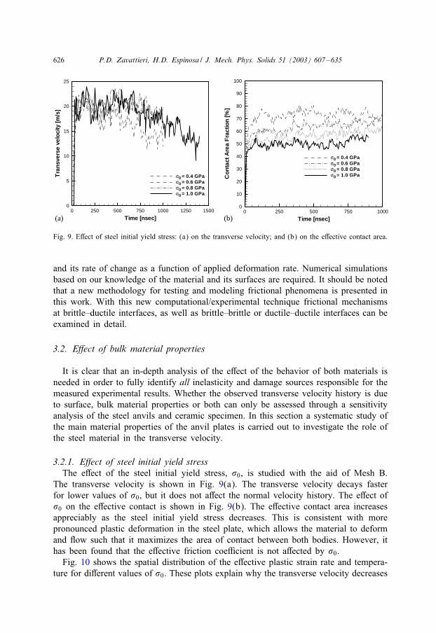
Fig. 9. EIect of steel initial yield stress: (a) on the transverse velocity; and (b) on the eIective contact area.
and its rate of change as a function of applied deformation rate. Numerical simulationsbased on our knowledge of the material and its surfaces are required. It should be notedthat a new methodology for testing and modeling frictional phenomena is presented inthis work. With this new computational/experimental technique frictional mechanismsat brittle–ductile interfaces, as well as brittle–brittle or ductile–ductile interfaces can beexamined in detail.
3.2. E:ect of bulk material properties
It is clear that an in-depth analysis of the eIect of the behavior of both materials isneeded in order to fully identify all inelasticity and damage sources responsible for themeasured experimental results. Whether the observed transverse velocity history is dueto surface, bulk material properties or both can only be assessed through a sensitivityanalysis of the steel anvils and ceramic specimen. In this section a systematic study ofthe main material properties of the anvil plates is carried out to investigate the role ofthe steel material in the transverse velocity.
3.2.1. E:ect of steel initial yield stressThe eIect of the steel initial yield stress, �0, is studied with the aid of Mesh B.
The transverse velocity is shown in Fig. 9(a). The transverse velocity decays fasterfor lower values of �0, but it does not aIect the normal velocity history. The eIect of�0 on the eIective contact is shown in Fig. 9(b). The eIective contact area increasesappreciably as the steel initial yield stress decreases. This is consistent with morepronounced plastic deformation in the steel plate, which allows the material to deformand Jow such that it maximizes the area of contact between both bodies. However, ithas been found that the eIective friction coe6cient is not aIected by �0.
Fig. 10 shows the spatial distribution of the eIective plastic strain rate and tempera-ture for diIerent values of �0. These plots explain why the transverse velocity decreases

P.D. Zavattieri, H.D. Espinosa / J. Mech. Phys. Solids 51 (2003) 607–635 627
Fig. 10. EIect of steel initial yield stress on the spatial distribution of the eIective plastic strain rate andtemperature.
more rapidly for �0=0:4 GPa, while the eIective contact area increases. Both, eIectiveplastic strain rate and temperature, spread more into the steel plate as �0 decreases.Likewise, the capability for transferring the shear traction is reduced and this event ismanifested in a decrease in transverse velocity. The large plastic deformation in thezone close to the surface maximizes the contact between the bodies but the reductionof shear stress controls the phenomenon.
3.2.2. E:ect of steel hardening exponentIn the previous calculations, a high value of the hardening exponent was consid-
ered (� = 1000). The hardening eIect is usually attributed to an increase in the stressneeded to induce the motion of dislocations after the material has accumulated largeplastic strains. On the surface, this phenomenon is altered due to the presence of thesurface. If the plastic deformation is localized only near the surface, dislocations inthe sub-surface can move towards the surface with more probability to be eliminatedby image dislocations. Since all the plastic deformation in these simulations is local-ized in a region near the free surface of the steel target, it is reasonable to assumelow hardening eIects in the visco-plastic model. In this section the eIect of hard-ening is examined for typical values of the hardening exponent (i.e. � = 5, 10, 50,etc.).

628 P.D. Zavattieri, H.D. Espinosa / J. Mech. Phys. Solids 51 (2003) 607–635
Time [nsec]
Tra
nsv
erse
velo
city
[m/s
]
0 250 500 750 1000 1250 15000
5
10
15
20
25
β = 5β = 10β = 50β = 100β =
Time [nsec]µ
250 500 750 10000.00
0.05
0.10
0.15
β = 5β = 10β = 50β = 100β = ∞∞
(a) (b)
Fig. 11. EIect of steel hardening exponent: (a) on the transverse velocity; and (b) on the eIective frictioncoe6cient.
Fig. 11(a) shows the eIect of the hardening exponent on the transverse velocity.This plot clearly shows an increase in velocity decay for those cases with low valuesof � (high hardening). Unlike the case with a low yield stress, where a similar behaviorwas observed, no plastic deformation is localized in the target near the contact surface.As in the previous analysis, the normal velocity history is not aIected by the hardeningexponent. Fig. 11(b) show the eIect of hardening on the eIective friction coe6cient.Unlike the case with low initial yield stress, the evolution of the eIective contact area issimilar for all Eve cases. However, the eIective friction coe6cient exhibits noticeablediIerences resulting in a lower value of 0eI for smaller values of �. Likewise, the ratein eIective friction coe6cient reduction is quite diIerent for each case. Compared withthe steel target, no signiEcant inelastic deformation is observed in the ceramic surface.This can be explained by the fact that the plastic deformation is diIused through thesteel plate instead of being localized at the peaks as in the case with �0 = 1 GPa. Asone would expect, the ceramic deforms more at high values of �0 or low values of �.
3.2.3. E:ect of ceramic fracture propertiesIn this section the damage parameters characterizing the ceramic response are evalu-
ated to study the eIect of the bulk ceramic behavior on the measured velocity histories.For such purpose, three diIerent grain boundary strengths (Tmax) have been considered(Tmax = 0:1, 1 and 10 GPa). In all cases KIC = 1:7 MPa
√m is used.
Fig. 12 shows the transverse velocity and crack pattern for the three diIerent val-ues of Tmax. It is observed that the normal and transverse velocities are not highlyaIected by the parameters of the interface elements within the choice of the steelmodel parameters. The microcrack pattern after 1 �s is also shown in the Egure. Al-though it is clear that the ceramic with a grain boundary strength of Tmax = 0:1 GPashows much more damage than when Tmax = 10 GPa, the diIerence in the trans-verse velocity is negligible compared with the eIect of any other parameter related

P.D. Zavattieri, H.D. Espinosa / J. Mech. Phys. Solids 51 (2003) 607–635 629
Time [nsec]
Tra
nsv
erse
velo
city
[m/s
]
0.000275 500 1000
0
5
10
15
20
25 Tmax = 0.1 GPaTmax = 1 GPaTmax = 10 GPa
Tmax= 0.1 GPa Tmax = 1 GPa Tmax= 10 GPa
Fig. 12. EIect of ceramic strength, Tmax, on the transverse velocity history.
to the frictional sliding. The implication is that the transverse velocity is dominatedby the interface behavior rather than by the amount of ceramic damage. This coun-terintuitive eIect can be explained by the fact that ceramic grains are highly conEnedwith no empty volume to accommodate any signiEcant relative motion between frag-ments. A completely diIerent behavior would be expected in the case of highly porousceramics.
4. Full-scale simulation
Full-scale simulations considering all of the key factors previously examined werecarried out. Frictional sliding, surface roughness, intergranular microcracking, plasticityand heat generation in the Jyer and target, and gap between specimen and Jyer havebeen included. Fig. 13 shows a schematics of the Enite element mesh generated takinginto account target, Jyer and specimen plates. The schematics of the boundary con-ditions is given in Fig. 3. For this analysis a grain size of 2 �m was considered andall the actual dimensions of the experiment were used (Espinosa et al., 2000b). Thethickness of the specimen is 540 �m and the width of the RVE is 100 �m. The gapbetween Jyer and specimen was also incorporated in the calculations. The roughnessof the target, Jyer and specimen are the same of those used in mesh B of Fig. 7, i.e.,Ra = 0:20 �m, RMS= 0:24 �m and � = 15 �m. The material parameters used in thesesimulations are speciEed in Tables 1–3.As discussed by Espinosa and Zavattieri (2002b), Zavattieri and Espinosa (2001) and
Zavattieri et al. (2001), it is physically incorrect to select a uniform Tmax and KIC for

630 P.D. Zavattieri, H.D. Espinosa / J. Mech. Phys. Solids 51 (2003) 607–635
x [µm]
y[µ
m]
0 100 200
0
200
400
600 Flyer
Specimen
Target
50 75 100 125
500
520
540
560
580
Gapδ = 10 µm
y [µ
m]
y [µ
m]
0 50 100
-3
-2
-1
0
1
2Ra = 0.19 µmRMS = 0.23 µm
Ra = 0.21 µmRMS = 0.22 µm
x [µm]
x [µm]
Fig. 13. Mesh with average grain size of 2 �m and surface roughness for full scale pressure–shear simulation.
all grain facets. Not only grain misorientation aIects interfacial strength, but also thepresence of glassy phase, glass pockets, and other impurities modify the ceramic grainboundary properties. Their random distribution leads to the consideration of a statisticalvariation in the interfacial strength dependent on grain misorientation and the presenceof second phases. In the following analyses, the interfacial strength parameters willbe described by a Weibull distribution. For instance the Weibull distribution for themaximum strength is given by
f(Tmax) =m(Tmax)m−1
T mmax0
exp[−(
Tmax
T 0max
)m]; Tmax ¿ 0:
A similar expression is used for the Weibull distribution for the fracture toughness KIC.The Weibull parameters used in the simulations are T 0
max =5 GPa, K0IC =1:7 MPa ·m1=2
and m = 3. These values have been independently identiEed for a similar ceramic byZavattieri and Espinosa (2001).One more detail has to be taken into consideration to simulate the real experiment.
As was discussed in reference to Fig. 1, the normal and transverse particle velocitiesshow a velocity reduction after an initial jump indicating the presence of a small gapbetween the Al2O3=SiC nanocomposite and the multi-plate Jyer. To determine the gapbetween the Jyer and the specimen, an analysis based only on elastic wave theory was

P.D. Zavattieri, H.D. Espinosa / J. Mech. Phys. Solids 51 (2003) 607–635 631
Time [nsec]
Nor
mal
velo
city
[m/s
]
0 250 500 750 10000
20
40
60
80
100
120
140
NumericalExperimental
Time [nsec]
Tra
nsv
erse
velo
city
[m/s
]
0 250 500 750 10000
5
10
15
20
25
NumericalExperimental
(a) (b)
Fig. 14. Comparison of velocity histories obtained from full scale simulation and experiment: (a) normalvelocity history; (b) transverse velocity history.
performed and compared with the experimental result. According to the duration ofthese pulses and the material parameters, a gap of approximately 10 �m was identiEedand used in the simulations.
4.1. Numerical results
Fig. 14 shows the normal and transverse velocity histories as they compared with theexperimental data. In this simulation, there is complete unloading until the gap betweenJyer and specimen closes. This is not observed in the experimental trace likely due tothe fact that in the real experiment there is a small but non-zero tilt between the Jyerand the specimen. Our modeling does not account for this eIect. Since this feature doesnot play any signiEcant role nor it changes the subsequently recorded velocity histories,we ignore it. Examination of Fig. 14 clearly shows that both normal and transversevelocity histories, numerically obtained, are in good agreement with the experimentaldata. In particular, the transverse velocity history captures the peak value of about20 m=s and the decay rate afterward.Fig. 15 shows the crack evolution and pattern during the Erst microsecond. Micro-
cracks initiate and propagate from the contact regions through the ceramic specimen.As the wave front advances, crack nucleation and growth occur up to the momentwhen the wave reaches the bottom face. A higher density of cracks is observed onthe ceramic–steel interfaces and most of the microcracking in the bulk of the ceramicremains diluted.
5. Conclusions
In this paper a grain-level micromechanical model is introduced and used to iden-tify failure mechanisms in pressure–shear experiments performed in brittle materials.

632 P.D. Zavattieri, H.D. Espinosa / J. Mech. Phys. Solids 51 (2003) 607–635
Fig. 15. Microcrack pattern in the ceramic specimen obtained from the full scale simulation.
The numerical results are discussed in terms of frictional eIects, microcracking andviscoplasticity in relation to recorded velocity histories.Two-dimensional simulations performed in this work and by Zavattieri et al. (2001)
demonstrate that pressure–shear plate impact velocity proEles do not attenuate sig-niEcantly even when accumulated damage within the specimen has extreme values.Although crack density and their patterns change from an almost intact ceramic to acompletely cracked ceramic, changes in normal and transverse velocity histories, withrespect to elastic predictions, are very subtle. This Ending shows that identiEcationof bulk properties in ceramics remains a very di6cult problem. With advances in thesynthesis of diamond and other ultra-hard materials, the possibility of designing con-Egurations in which the Jyer and target plates remain elastic, not only in the bulkbut also at the surfaces, appears feasible. None of the pressure–shear experiments per-formed on hard brittle materials, which are reported in the literature, seems to meet thisvery demanding requirement. Therefore, based on the Endings presented here, one can

P.D. Zavattieri, H.D. Espinosa / J. Mech. Phys. Solids 51 (2003) 607–635 633
conclude that surface eIects are dominant and responsible for the observed attenuationfrom elastic predictions.As mentioned in early work, ceramics are so susceptible to fragmentation, because
of their low toughness, that they represent the most di6cult materials to be investigatedin wave propagation experiments with specimen recovery. Nonetheless, the simulationspresented here show that our computational methodology is very valuable in the iden-tiEcation of dominant failure modes and in particular in the study of dynamic frictionof hard brittle materials.In this study, it has been observed that the normal velocity does not change from its
theoretical value, obtained from elastic wave theory, even when contact and frictionalsliding between bodies is considered. It has also been demonstrated that the transversevelocity history is highly dependent on the frictional sliding between the specimen andthe target and that the phenomenon is highly sensitive to three key features: (1) plasticbehavior of the softer material, steel target in this work, (2) surface roughness of bothmaterials, and (3) applied pressure. None of these factors are directly related to thebulk inelastic behavior of the brittle specimen being tested.Since the velocity histories taken from the back of the target are the only information
available to the analyst, it can be concluded that pressure–shear experimental records,per se, are not su6cient to determine the mechanical behavior of brittle materials.However, when the experiments are analyzed by our grain level stochastic model,fundamental insight into dominant failure mechanisms, damage and inelasticity temporaland spatial distribution are obtained.Our micromechanical model can be used to simulate the pressure–shear conEgura-
tion for diIerent impact velocities and angles, such that a relationship between crackdensity evolution and state of stress, temperature and initial damage is obtained. In thisway, bridging between length scales can be accomplished not only to micromechan-ically characterize diIerent brittle materials but also to use this information to reEnetheoretical formulations such as the multiple-plane microcracking model proposed byEspinosa (1995). Likewise, other frictional conEgurations can be modeled using thecomputational framework presented in this paper.Another application that can take full advantage of our grain level model is the
investigation of friction and reliability of microelectromechanical systems (MEMS).Friction and wear is the dominant failure mode in applications such as the Sandiamicroengine, Tanner et al. (1998).
Acknowledgements
The authors acknowledge ARO and DoD HPCMP for providing supercomputer timeon the 128 processors Origin 2000 at the Naval Research Laboratory—DC (NRL-DC).This research was supported by the National Science Foundation through Career AwardNos. CMS 9523113, CMS-9624364, the O6ce of Naval Research YIP through AwardNo. N00014-97-1-0550, the Army Research O6ce through ARO-MURI Award No.DAAH04-96-1-0331 and the Air Force O6ce of ScientiEc Research through AwardNo. F49620-98-1-0039.

634 P.D. Zavattieri, H.D. Espinosa / J. Mech. Phys. Solids 51 (2003) 607–635
References
Buscaglia, G., Dari, E., 1997. Anisotropic mesh optimization and its applications in adaptivity. Int. J. Numer.Methods Eng. 40, 4119–4136.
Buscaglia, G., Dari, E., Zavattieri, P., 1997. Mesh optimization: some results in 3d elasticity. ZElasticitZe,ViscoZelasticitZe; et Controle Optimal ESAIM: Proceedings Lyon, France, pp. 1–16.
Camacho, G., Ortiz, M., 1996a. Adaptive Lagrangian modelling of ballistic penetration of metallic targets.Comput. Methods Appl. Mech. Eng. 142, 269–301.
Camacho, G.T., Ortiz, M., 1996b. Computational modeling of impact damage in brittle materials. Int. J.Solids Struct. 33, 2899–2938.
Clifton, R., Klopp, R., 1985. Pressure-shear plate impact testing. In: ASM Metal Handbook, Vol. 8, 9thEdition, American Society of Metals, Materials Park, OH, pp. 230–238.
Curran, D., Seaman, L., Cooper, T., Shockey, D., 1990. Micromechanical model for communication andgranular Jow of brittle material under high strain rate application to penetration of ceramic targets. Int.J. Impact Eng. 13, 53–83.
Espinosa, H., 1992. Micromechanics of the dynamic response of ceramics and ceramic composites. Ph.D.Thesis, Brown University, Providence, RI.
Espinosa, H., 1995. On the dynamic shear resistance of ceramic composites and its dependence on appliedmultiaxial deformation. Int. J. Solids Struct. 32, 3105.
Espinosa, H., Nemat-Nasser, S., 2000. Low velocity impact experiments. In: Lampan, S. (Ed.), Handbook,Vol. 8. ASM International, Metals Park.
Espinosa, H., Zavattieri, P., 2002a. A grain level model for the study of failure initiation and evolution inpolycrystalline brittle materials, Part I: theory and numerical implementation. Mech. Mater., in press.
Espinosa, H., Zavattieri, P., 2002b. A grain level model for the study of dynamic failure initiation andevolution in polycrystalline brittle materials, Part II: numerical examples. Mech. Mater., in press.
Espinosa, H., Raiser, G., Clifton, R., Ortiz, M., 1992. Experimental observations and numerical modeling ofinelasticity in dynamically loaded ceramics. J. Hard Mater. 3, 285–313.
Espinosa, H., Mello, M., Xu, Y., 1997. A variable sensitivity displacement interferometer with applicationto wave propagation experiments. J. Appl. Mech. 64, 123–131.
Espinosa, H., Zavattieri, P., Dwivedi, S., 1998a. A Enite deformation continuum/discrete model for thedescription of fragmentation and damage in brittle materials. J. Mech. Phys. Solids 46 (10), 1909–1942.
Espinosa, H., Zavattieri, P., Emore, G., 1998b. Adaptive FEM computation of geometric and materialnonlinearities with application to brittle failure. Mech. Mater. 29, 275–305.
Espinosa, H., Dwivedi, S., Lu, H.-C., 2000a. Modeling impact induced delamination of woven Eber reinforcedcomposites with contact/cohesive laws. Comput. Methods Appl. Mech. Eng. 189, 259–290.
Espinosa, H., Patanella, A., Xu, Y., 2000b. Dynamic compression-shear response of brittle materials withspecimen recovery. Exp. Mech. 40 (3), 321–330.
Espinosa, H., Lu, H.-C., Zavattieri, P., Dwivedi, S., 2001. A 3-d Enite deformation anisotropic visco-plasticitymodel for Eber composites. J. Compos. Mater. 35 (5), 369–410.
Hearmon, R., 1956. The elastic constants of anisotropic materials ii. Adv. Phys. 5, 323–382.Machcha, A., Nemat-Nasser, S., 1994. Pressure-shear recovery experiments. Mech. Mater. 18, 49–53.Ortiz, M., PandolE, A., 1999. Finite-deformation irreversible cohesive elements for three-dimensional
crack-propagation analysis. Int. J. Numer. Methods Eng. 44 (9), 1267–1282.Raiser, G., 1993. Dynamic failure resistance of ceramics and glasses. Ph.D. Thesis, Brown University,
Providence, RI.Raiser, G., Clifton, R., Ortiz, M., 1990. A soft-recovery plate impact experiment for studying microcracking
in ceramics. Mech. Mater. 10, 43–58.Raiser, G., Wise, J., Clifton, R., Grady, D., Cox, D., 1994. Plate impact response of ceramics and glasses.
J. Appl. Phys. 75 (8), 3862–3869.Tanner, D., Peterson, K., Irwin, L., Tangyunyong, P., Miller, W., Eaton, W., Smith, N., Rodgers, S., 1998.
Linkage design eIect on the reliability of surface micromachined microengines driving a load. Proceedingsof SPIE, Micromachining and Microfabrication Symposium, Vol. 3512, Santa Clara, CA, pp. 225–226.

P.D. Zavattieri, H.D. Espinosa / J. Mech. Phys. Solids 51 (2003) 607–635 635
Taylor, L., Flanagan, D., 1987. Pronto 2d: a two dimensional transient solid dynamics program. SandiaReport SAND86.
Tvergaard, V., 1990. EIect of Ebre debonding in a whisker-reinforced material. Mater. Sci. Eng. A 125,203.
Xu, X.-P., Needleman, A., 1995. Numerical simulation of dynamic interfacial crack growth allowing forcrack growth away from the bond line. Int. J. Fract. 74, 253–275.
Yadav, S., Davis, J., Ramesh, K., 1993. Damage and recovery experiments using pressure-shear plate impact.In: Experimental Techniques in the Dynamics of Deformable Solids. American Society of MechanicalEngineers, Applied Mechanics Division, AMD, NY, USA, Vol. 165, pp. 71–78.
Zavattieri, P., Espinosa, H., 2001. Grain level model analysis of crack initiation and propagation in brittlematerials. Acta Mater. 49, 4291–4311.
Zavattieri, P., Buscaglia, G., Dari, E., 1996a. Finite element mesh optimization in three dimensions. LatinAmer. Appl. Res. 26, 233–236.
Zavattieri, P., Dari, E.A., Buscaglia, G., 1996b. Optimization strategies in unstructured mesh generation. Int.J. Numer. Methods Eng. 39, 2055–2071.
Zavattieri, P., Raghuram, P., Espinosa, H., 2001. A computational model of ceramic microstructures subjectedto multi-axial dynamic loading. J. Mech. Phys. Solids 49 (1), 27–68.
Zhou, M., Needleman, A., Clifton, R., 1994. Finite element simulations of shear localization in plate impact.J. Mech. Phys. Solids 42 (3), 423–458.