An evolutional domain oriented approach to problem solving based on web service composition
161
University of Iowa Iowa Research Online eses and Dissertations 2013 An evolutional domain oriented approach to problem solving based on web service composition Cuong Kien Bui University of Iowa Copyright 2013 Cuong Kien Bui is dissertation is available at Iowa Research Online: hp://ir.uiowa.edu/etd/2448 Follow this and additional works at: hp://ir.uiowa.edu/etd Part of the Computer Sciences Commons Recommended Citation Bui, Cuong Kien. "An evolutional domain oriented approach to problem solving based on web service composition." PhD (Doctor of Philosophy) thesis, University of Iowa, 2013. hp://ir.uiowa.edu/etd/2448.
Transcript of An evolutional domain oriented approach to problem solving based on web service composition

University of IowaIowa Research Online
Theses and Dissertations
2013
An evolutional domain oriented approach toproblem solving based on web service compositionCuong Kien BuiUniversity of Iowa
Copyright 2013 Cuong Kien Bui
This dissertation is available at Iowa Research Online: http://ir.uiowa.edu/etd/2448
Follow this and additional works at: http://ir.uiowa.edu/etd
Part of the Computer Sciences Commons
Recommended CitationBui, Cuong Kien. "An evolutional domain oriented approach to problem solving based on web service composition." PhD (Doctor ofPhilosophy) thesis, University of Iowa, 2013.http://ir.uiowa.edu/etd/2448.

AN EVOLUTIONAL DOMAIN ORIENTED APPROACH TO PROBLEM SOLVING
BASED ON WEB SERVICE COMPOSITION
by
Cuong Kien Bui
An Abstract
Of a thesis submitted in partial fulfillment of therequirements for the Doctor of Philosophy
degree in Computer Sciencein the Graduate College of
The University of Iowa
May 2013
Thesis Supervisor: Professor Emeritus Teodor Rus

1
ABSTRACT
Computers are around us and integrated deeply in almost every aspect of human life.
Computers are used to solve more and more types of problems inhuman lives. Software
tools are designed to ease the process of integrating computers into our problem solving
process.
To use computers to solve a problem with current software technology a computer
user can either buy a software designed specifically for thatproblem or she needs to learn a
general computer programming language to write computer programs to solve the problem.
Even though, with computer software the user can solve that specific problem; it is still
challenging to truly use that software as a tool to integratethe computer within the problem
solving process. On the other hand, learning a computer language is not an easy task for
most domain experts such as chemists, biologists, etc. The level of skills required for a
domain expert to be able to translate a domain concept to a computer language concept is
also high.
As an alternative, we want to create tools that enable problem solvers to express
problem solving solutions in terms characteristic to theirown domain and carry out prob-
lem solving processes in those terms. This thesis provides acontribution to the domain
oriented software development and describes an implementation of this approach as a pro-
totype system called DALSystem. In this approach, a problemdomain is first formalized
using a domain ontology, then the domain expert expresses her solution algorithm using
the terms of that ontology. The expression of her solution algorithm is then translated to

2
the intermediate language of a domain dedicated virtual machine (DDVM) and is evaluated
by an interpreter using the domain ontology. The solution algorithm can later be imported
into the domain ontology thus expanding the problem domain with new concepts (action
and data) in a process called Domain Ontology Evolution (DOE).
With this methodology, the DALSystem can execute algorithms whose expressions
are conceptual, similar to the way the human brain would execute them. We illustrate this
methodology using DALSystem in the domain of arithmetic.
Abstract Approved:Thesis Supervisor
Title and Department
Date

AN EVOLUTIONAL DOMAIN ORIENTED APPROACH TO PROBLEM SOLVING
BASED ON WEB SERVICE COMPOSITION
by
Cuong Kien Bui
A thesis submitted in partial fulfillment of therequirements for the Doctor of Philosophy
degree in Computer Sciencein the Graduate College of
The University of Iowa
May 2013
Thesis Supervisor: Professor Emeritus Teodor Rus

Graduate CollegeThe University of Iowa
Iowa City, Iowa
CERTIFICATE OF APPROVAL
PH.D. THESIS
This is to certify that the Ph.D. thesis of
Cuong Kien Bui
has been approved by the Examining Committee for the the-sis requirement for the Doctor of Philosophy degree in Com-puter Science at the May 2013 graduation.
Thesis Committee:Teodor Rus, Thesis Supervisor
James Cremer
Alice Davison
David Eichmann
Juan Pablo Hourcade
Gregg Oden

ACKNOWLEDGEMENTS
I would like to thank first the members of my thesis committee:James Cremer,
David Eichmann, Alice Davison, Gregg Oden, Juan Pablo Hourcade, and especially my
advisor, Teodor Rus, who suggested the topic for this work and patiently provided enor-
mous guidance throughout.
David Eichmann also deserves thanks for providing an innovative research environ-
ment and stimulating ideas about the applications of ontologies and language processing
during his student meetings every week. I also would like to thank other students of Insti-
tute of Clinical and Translational Science: Todd Papke, Si-Chi Chin, Charisse Madlock-
Brown, Ray Hylock, Brandyn Kusenda and Jimmy (James Schappet) for their support, they
were interesting people to have around.
I would like to thank my parents, Quoc Kien Bui and The Thi Nguyen, for giving
me the opportunities to do these things. I can’t thank them enough, but at least I can say
“Con cam on bo me that nhieu!” The next two very important people to me are my wife
Hang Nguyen and my son Bao Bui. I would like to thank them for their love, support and
encouragement me to finish this work. I am also pleased to acknowledge all the help of my
sister during the last 4 months of this work. Thanks, guys.
Finally, I would like to thank the Department of Computer Science at the University
of Iowa for their support, especially Sheryl Semler and Catherine Till. I also would like to
thank Vietnam Education Foundation (VEF) for granting me the PhD fellowship.
ii

ABSTRACT
Computers are around us and integrated deeply in almost every aspect of human life.
Computers are used to solve more and more types of problems inhuman lives. Software
tools are designed to ease the process of integrating computers into our problem solving
process.
To use computers to solve a problem with current software technology a computer
user can either buy a software designed specifically for thatproblem or she needs to learn a
general computer programming language to write computer programs to solve the problem.
Even though, with computer software the user can solve that specific problem; it is still
challenging to truly use that software as a tool to integratethe computer within the problem
solving process. On the other hand, learning a computer language is not an easy task for
most domain experts such as chemists, biologists, etc. The level of skills required for a
domain expert to be able to translate a domain concept to a computer language concept is
also high.
As an alternative, we want to create tools that enable problem solvers to express
problem solving solutions in terms characteristic to theirown domain and carry out prob-
lem solving processes in those terms. This thesis provides acontribution to the domain
oriented software development and describes an implementation of this approach as a pro-
totype system called DALSystem. In this approach, a problemdomain is first formalized
using a domain ontology, then the domain expert expresses her solution algorithm using
the terms of that ontology. The expression of her solution algorithm is then translated to
iii

the intermediate language of a domain dedicated virtual machine (DDVM) and is evaluated
by an interpreter using the domain ontology. The solution algorithm can later be imported
into the domain ontology thus expanding the problem domain with new concepts (action
and data) in a process called Domain Ontology Evolution (DOE).
With this methodology, the DALSystem can execute algorithms whose expressions
are conceptual, similar to the way the human brain would execute them. We illustrate this
methodology using DALSystem in the domain of arithmetic.
iv

TABLE OF CONTENTS
LIST OF TABLES . . . . . . . . . . . . . . . . . . . . . . . . . . . . . . . . . . . viii
LIST OF FIGURES . . . . . . . . . . . . . . . . . . . . . . . . . . . . . . . . . . . ix
LIST OF ALGORITHMS . . . . . . . . . . . . . . . . . . . . . . . . . . . . . . . . x
LIST OF LISTINGS . . . . . . . . . . . . . . . . . . . . . . . . . . . . . . . . . . xi
CHAPTER
1 INTRODUCTION . . . . . . . . . . . . . . . . . . . . . . . . . . . . . . . 1
1.1 Problem Solving Process on Computers . . . . . . . . . . . . . . . .. 11.2 Domain Modeling Using Ontologies . . . . . . . . . . . . . . . . . . 31.3 Domain Solution Algorithm and Web Execution . . . . . . . . . .. . 51.4 System . . . . . . . . . . . . . . . . . . . . . . . . . . . . . . . . . . 6
2 RELATED WORK . . . . . . . . . . . . . . . . . . . . . . . . . . . . . . . 9
2.1 Computational Languages for a Domain . . . . . . . . . . . . . . . .92.1.1 Natural Language Programming . . . . . . . . . . . . . . . . 10
2.1.1.1 Top-down Approach . . . . . . . . . . . . . . . . . 102.1.1.2 Bottom-up Approach . . . . . . . . . . . . . . . . . 12
2.1.2 Domain Specific Languages . . . . . . . . . . . . . . . . . . 152.2 Web Service Composition . . . . . . . . . . . . . . . . . . . . . . . . 18
2.2.1 Web Service Composition using Workflows . . . . . . . . . . 192.2.2 Web Service Composition using AI Planning . . . . . . . . . 202.2.3 Web Service Composition using Hybrid Approach . . . . . .. 22
3 PROCESS OF DEFINING DOMAIN ONTOLOGY . . . . . . . . . . . . . 26
3.1 Domain Ontology . . . . . . . . . . . . . . . . . . . . . . . . . . . . 273.2 CEAD Ontology . . . . . . . . . . . . . . . . . . . . . . . . . . . . . 303.3 Associating Domain Concepts with Web Services . . . . . . . .. . . 343.4 Discussion . . . . . . . . . . . . . . . . . . . . . . . . . . . . . . . . 36
4 DOMAIN ALGORITHMIC LANGUAGE . . . . . . . . . . . . . . . . . . 39
4.1 Examples of DAL(D) . . . . . . . . . . . . . . . . . . . . . . . . . . 414.1.1 A DAL for Arithmetic Domain . . . . . . . . . . . . . . . . . 41
v

4.1.2 High School Algebra . . . . . . . . . . . . . . . . . . . . . . 424.1.3 Linear Algebra . . . . . . . . . . . . . . . . . . . . . . . . . 434.1.4 User Dictionary . . . . . . . . . . . . . . . . . . . . . . . . . 43
4.2 DAL Specification for Arithmetic Domain . . . . . . . . . . . . . .. 444.2.1 Rule Representation . . . . . . . . . . . . . . . . . . . . . . . 46
4.2.1.1 Characters . . . . . . . . . . . . . . . . . . . . . . 464.2.2 Lexical elements . . . . . . . . . . . . . . . . . . . . . . . . 464.2.3 Declarations . . . . . . . . . . . . . . . . . . . . . . . . . . . 484.2.4 Terms (expressions) . . . . . . . . . . . . . . . . . . . . . . . 524.2.5 Commands (statements) . . . . . . . . . . . . . . . . . . . . . 54
4.3 DAL Use . . . . . . . . . . . . . . . . . . . . . . . . . . . . . . . . . 56
5 DOMAIN DEDICATED VIRTUAL MACHINE AND SADL LANGUAGE 58
5.1 Domain Dedicated Virtual Machine . . . . . . . . . . . . . . . . . . .585.2 Structure of SADL File . . . . . . . . . . . . . . . . . . . . . . . . . 615.3 DDVM Conceptual Instructions . . . . . . . . . . . . . . . . . . . . . 64
5.3.1 Declaration Intructions . . . . . . . . . . . . . . . . . . . . . 655.3.2 Virtual Register Traffic . . . . . . . . . . . . . . . . . . . . . 665.3.3 Action Instructions . . . . . . . . . . . . . . . . . . . . . . . 675.3.4 Field Access Instructions . . . . . . . . . . . . . . . . . . . . 695.3.5 Branching . . . . . . . . . . . . . . . . . . . . . . . . . . . . 70
6 TRANSLATION FROM DAL TO SADL . . . . . . . . . . . . . . . . . . . 71
6.1 ConceptGeneratorVisitor . . . . . . . . . . . . . . . . . . . . . . . . 736.1.1 Literals . . . . . . . . . . . . . . . . . . . . . . . . . . . . . 746.1.2 Local Reference . . . . . . . . . . . . . . . . . . . . . . . . . 746.1.3 Computing Expressions . . . . . . . . . . . . . . . . . . . . . 756.1.4 Assignment . . . . . . . . . . . . . . . . . . . . . . . . . . . 776.1.5 Phrase Node . . . . . . . . . . . . . . . . . . . . . . . . . . . 786.1.6 Field Reference . . . . . . . . . . . . . . . . . . . . . . . . . 796.1.7 Array Reference . . . . . . . . . . . . . . . . . . . . . . . . . 796.1.8 Conditional Branching . . . . . . . . . . . . . . . . . . . . . 806.1.9 Loops . . . . . . . . . . . . . . . . . . . . . . . . . . . . . . 82
6.2 LHSVisitor . . . . . . . . . . . . . . . . . . . . . . . . . . . . . . . . 836.2.1 Local References . . . . . . . . . . . . . . . . . . . . . . . . 836.2.2 Field Reference . . . . . . . . . . . . . . . . . . . . . . . . . 836.2.3 Array Reference . . . . . . . . . . . . . . . . . . . . . . . . . 84
7 DOMAIN ONTOLOGY EVOLUTION . . . . . . . . . . . . . . . . . . . . 86
7.1 Creating new Action Concepts - add2Onto . . . . . . . . . . . . . .. 867.2 Creating new Data Concepts - addData2Onto . . . . . . . . . . . .. . 95
vi

7.2.1 Creating composed data concepts . . . . . . . . . . . . . . . . 957.2.2 Creating array data concepts . . . . . . . . . . . . . . . . . . 99
8 DALSYSTEM . . . . . . . . . . . . . . . . . . . . . . . . . . . . . . . . . 102
8.1 DALSystem Deployment . . . . . . . . . . . . . . . . . . . . . . . . 1028.2 SADL Servlet . . . . . . . . . . . . . . . . . . . . . . . . . . . . . . 1058.3 Implementation of DDVM . . . . . . . . . . . . . . . . . . . . . . . . 108
9 CONCLUSIONS . . . . . . . . . . . . . . . . . . . . . . . . . . . . . . . 110
APPENDIX . . . . . . . . . . . . . . . . . . . . . . . . . . . . . . . . . . . . . . . 113
A DALSYSTEM USER MANUAL . . . . . . . . . . . . . . . . . . . . . . . 113
B CEAD ONTOLOGY OWL FILE . . . . . . . . . . . . . . . . . . . . . . . 126
C HOUSEHOLDER REDUCTION ALGORITHMS . . . . . . . . . . . . . . 131
D SADL CODE FOR EUCLIDEAN ALGORITHM . . . . . . . . . . . . . . 136
REFERENCES . . . . . . . . . . . . . . . . . . . . . . . . . . . . . . . . . . . . . 138
vii

LIST OF TABLES
Table
3.1 Data properties for CEAD concepts . . . . . . . . . . . . . . . . . . .. . . . 34
3.2 addInstance1 properties . . . . . . . . . . . . . . . . . . . . . . . . . .. . . . 36
7.1 Patterns for generating WSDL files . . . . . . . . . . . . . . . . . . .. . . . . 89
7.2 Patterns for generating OWL individual . . . . . . . . . . . . . .. . . . . . . 91
A.1 DAL operators . . . . . . . . . . . . . . . . . . . . . . . . . . . . . . . . . . 115
viii

LIST OF FIGURES
Figure
1.1 Arithmetic modeling tree . . . . . . . . . . . . . . . . . . . . . . . . . .. . . 4
1.2 DALSystem Architecture . . . . . . . . . . . . . . . . . . . . . . . . . . .. . 7
3.1 Overview of CEAD Ontology . . . . . . . . . . . . . . . . . . . . . . . . . .31
3.2 Object properties among CEAD concepts for data modeling. . . . . . . . . . 32
6.1 DAL Translator processing pipeline . . . . . . . . . . . . . . . . .. . . . . . 72
8.1 DALSystem components deployment . . . . . . . . . . . . . . . . . . .. . . 103
8.2 Cloud Implementation of the DALSystem . . . . . . . . . . . . . . .. . . . . 106
ix

LIST OF ALGORITHMS
Algorithm
6.1 Generating literal load algorithm . . . . . . . . . . . . . . . . . .. . . . . . . 74
6.2 Generating local reference algorithm . . . . . . . . . . . . . . .. . . . . . . . 75
6.3 Generating computing expression algorithm . . . . . . . . . .. . . . . . . . . 76
6.4 Generating assignment algorithm . . . . . . . . . . . . . . . . . . .. . . . . . 77
6.5 Generating phrases algorithm . . . . . . . . . . . . . . . . . . . . . .. . . . . 78
6.6 Generating field reference algorithm . . . . . . . . . . . . . . . .. . . . . . . 79
6.7 Generating array reference algorithm . . . . . . . . . . . . . . .. . . . . . . . 80
6.8 Generating conditional branching algorithm . . . . . . . . .. . . . . . . . . . 81
6.9 Generating loops algorithm . . . . . . . . . . . . . . . . . . . . . . . .. . . . 83
6.10 Generating LHS local reference algorithm . . . . . . . . . . .. . . . . . . . . 84
6.11 Generating LHS field reference algorithm . . . . . . . . . . . .. . . . . . . . 84
6.12 Generating LHS array reference algorithm . . . . . . . . . . .. . . . . . . . . 85
7.1 Creating new action concept algorithm . . . . . . . . . . . . . . .. . . . . . . 87
7.2 Creating new action concept individual algorithm . . . . .. . . . . . . . . . . 90
x
LIST OF LISTINGS
Listing
2.1 A natural language program in NaturalJava. . . . . . . . . . . .. . . . . . . . 11
2.2 Travel reservation procedure using Golog. O, D, D1, D2 are Origin, Destina-tion, Departure time, Return Time respectively. . . . . . . . . .. . . . . . . . 20
3.1 OWL file for arithmetic ontology in Figure 1.1 . . . . . . . . . .. . . . . . . . 29
3.2 Reasoning rules aboutcastableproperty . . . . . . . . . . . . . . . . . . . . . 33
3.3 Data conceptInteger definition in OWL . . . . . . . . . . . . . . . . . . . 35
3.4 Action conceptadd definition in OWL . . . . . . . . . . . . . . . . . . . . . 37
4.1 Dictionary entries for Arithmetic Domain . . . . . . . . . . . .. . . . . . . . 45
4.2 Euclidean algorithm for finding GCD of two integers . . . . .. . . . . . . . . 57
5.1 Declaration section of SADL file . . . . . . . . . . . . . . . . . . . . .. . . . 62
5.2 Two push instructions for complex data types then addingthem together usingaddComplex concept . . . . . . . . . . . . . . . . . . . . . . . . . . . . . . . 63
7.1 DAL algorithm for solving quadratic equations . . . . . . . .. . . . . . . . . 92
7.2 The generated SADL file for Solver concept. . . . . . . . . . . . .. . . . . . 93
7.3 OWL entry for the Solver concept. . . . . . . . . . . . . . . . . . . . .. . . . 94
B.1 Action conceptadd definition in OWL . . . . . . . . . . . . . . . . . . . . . 126
C.1 Compute the scalar product of two vectors . . . . . . . . . . . . .. . . . . . . 131
C.2 HouseHolder elimination concept . . . . . . . . . . . . . . . . . . .. . . . . 132
C.3 HouseHolder elimination concept . . . . . . . . . . . . . . . . . . .. . . . . 133
C.4 HouseHolder transformation concept . . . . . . . . . . . . . . . .. . . . . . . 133
xi

C.5 HouseHolder Linear Equation System Solver concept . . . .. . . . . . . . . . 134
C.6 A test for HouseHolder Linear Equation System Solver concept . . . . . . . . 135
D.1 SADL code for Euclidean algorithm . . . . . . . . . . . . . . . . . . .. . . . 136
xii
1
CHAPTER 1INTRODUCTION
The concept of “Liberating Computer User from Programming”first appeared in
2008 (Rus 2008). This concept does not mean that programmingwould disappear; rather,
it means that while computer programming will be performed by computer programmers,
computer use in a domain of application will be performed by adomain expert using a
domain algorithmic language (DAL) (Rus 2013). This impliesthe development of software
tools that allow the computer user to use the computer transparently during her problem
solving process. In other words, the user can use the computer for solving problems without
worrying about the computer platform they are running on andthe computer language used
to program the solution algorithm. Therefore, in the resulting software methodology, the
computer is considered as a tool integrated into human problem solving process. This thesis
provides an implementation of this idea for the domain of arithmetic.
1.1 Problem Solving Process on Computers
Originally, computers have not been developed as problem solving tools. Instead,
they were invented by mathematicians and engineers as number crunching tools. Within
the framework of original creators of computers, the computer use during problem solving
process follows Polya’s (1945) problem solving methodology and consists of the following
steps:
1. Formulate the problem;
2. Develop a solution algorithm;

2
3. Encode the algorithm and its data into aprogramin the language of the computer;
4. Let the computer execute the programs;
5. Decode the result and extract the solution of your problem.
Even though this approach of using the computer as a problem solving tool serves the
original creators (physicists and mathematicians) well tosome extent, it does require the
computer user to understand computer architecture and functionality to be able to encode
the algorithm into a program. This requirement turns out to be a huge obstacle for other
domain experts such as chemists, biologists and engineers,to be able to use computers for
their computations. Computer experts then try to diminish this difficulty by developing
software tools like operating systems, programming languages, compilers and interpreters.
The idea of these software tools is to raise machine languageabstraction level towards the
logical level of problem solving process. Therefore these software tools abstract away the
thinking in terms of binary signal processing at the machinelevel. But the machine com-
putation concepts which these tools use do not represent theconcepts used by the domain
experts during the human problem solving process. They represent concepts that belong to
the computer architecture and functionality. Therefore, in order to use the computer during
the problem solving process, the computer user needs to learn computer architecture and
functionality as well as the new language provided by software tools. Consequently, this
framework requires a higher level of professionalism from the computer user. As the num-
ber and the complexity of problems domains increases, the complexity of the software tools
supporting the problem solving process by translation fromproblem domain language into
software tools languages increases dramatically. As a consequence, this framework of fit-

3
ting the problem solving process within the computer increases the complexity of computer
software to a level where it threatens to kill the computer technology itself (Horn 2001).
This thesis proposes a solution for the problem of integrating computers in the prob-
lem solving process by making the steps (1) and (3-4) of the computer-based problem solv-
ing process easier for computer users. In our approach, domain concepts are first organized
in an ontology using domain characteristic terms. Those concepts are then associated with
their computational meanings with some initial help from computer experts. Next, the solu-
tion algorithm in steps (3-4) can be written in these domain terms, while the algorithm can
later be executed on a computer network by a virtual machine which searches the compu-
tational meanings of these domain terms in the domain ontology. This thesis also provides
a working system to demonstrate our approach, called DALSystem.
1.2 Domain Modeling Using Ontologies
The first step in our approach to the problem solving process is to organize problem
domain concepts in an ontology. Domain experts perform thisstep by recognizing concepts
that characterize the problem domain. This step in problem formalization means that the
problem solver defines problem concepts and methods in termsof well-understood con-
cepts and methods. Using a mathematical saying, “one cannotexpect to be able to solve a
problem one does not understand". For example, in the domainof arithmetic such concepts
are number, integer, real, add, multiply, subtract, divide, etc.
For the domain of computational linguistics, such conceptsareword, phrase, sentence,
category, parse tree, parse, stemmer, etc. Those characteristic concepts

4
form thepure domain ontology. Methodologies and tools for constructing such ontologies
can be found in (Welty & Guarino 2001, Gasevic, Djuric & Devedzic 2009). Figure 1.1
shows an example of how arithmetic domain concepts can be organized.
Arithmetic modeling tree
Number
Complex
Real
Rational
Integer
Irrational
Operator
Unary
{−, !}
Binary
{+,−, ∗, /}
Figure 1.1: Arithmetic modeling tree
Our conjecture here is that solvable problems of any problemdomain are express-
ible in terms of a finite number of well defined concepts. This is trivially true for the
common sense problems raised by the usual real-life. A formal proof of this conjecture can
actually be sought using decidability theory (Sipser 2006).

5
1.3 Domain Solution Algorithm and Web Execution
The next step in our approach is the collaboration between domain expert and
computer expert to associate concepts in the pure domain ontology with their computa-
tional meaning implemented by web services or XML data types. I choose to use web
services using industry standards such as SOAP (Box, Ehnebuske, Kakivaya, Layman,
Mendelsohn, Nielsen, Thatte & Winer 2000), WSDL (Christensen, Curbera, Meredith &
Weerawarana 2001), UDDI (Clement, Hately, von Riegen & Rogers 2004) as the imple-
mentation of computational meanings of domain concepts to make the system have a better
impact on the community. In this step, the computer expert uses a meta-ontology called
CEADOntology, which will be discussed later in Section 3.2,to associate each domain
concept with its computational meaning as
• an execution agent if the domain concept is an action concept such asadd, multiply,
subtract, divide, etc.
• an XSD data type if the domain concept is a data concept such as integer,
real, etc.
Each execution agent could be implemented by several service instances so that if one
service instance is not available another one can take its place.
Finally, to support the domain expert in expressing her computation in domain
terms, a language specific to that domain is created with the help of a computer expert.
However, unlike other domain specific languages (DSL) wherethe meaning of each ex-
pression is fixed, this language only provides a general mechanism for logically composing
meanings of domain terms. The concrete meanings of domain terms are specified by the

6
ontology. Therefore the meaning of each expression in this language is inherently dynamic,
depending on the state of the ontology.
Problem solutions (algorithms) are then expressed in termsof concepts and oper-
ations characteristic to the domain. These expressions areactually valid expressions in
the domain language of the problem solvers, which are understood by all domain experts
because these expressions use only concepts familiar to thedomain experts.
Solution algorithms to the problem solved this way can be stored in the domain
ontology by tuples(term, solution algorithm). This way the knowledge obtained by
problem solving become new domain concepts that can be reused to solve other problems.
This is the domain evolution process that can be iterated indefinitely. Thus, the user do-
main ontology will expand indefinitely during the process ofthe domain expert solving her
problems.
1.4 System
To support our approach to the problem solving process, we identify the following
software tools as needed:
1. Tools for domain specification using an ontology. Protege1 is an excellent off-the-
shelf tool for this purpose.
2. A virtual machine which operates on domain ontology to prepare data and make
appropriate calls to web services implementing action concepts, called Domain Ded-
icated Virtual Machine (DDVM).
1Available at http://protege.stanford.edu/

7
Domain User DAL Console
DAL
Translator
Virtual
Machine
Network
Ontologies
Web Services
Ontology
Manager
use
1. DAL expr.
2. SADL expr.
3. execute
4. XML result
5. result
6. display result
add new
conceptimplementedBy
query query
7. publish concept
Figure 1.2: DALSystem Architecture
3. A translator to map the domain algorithmic language to theDDVM execution lan-
guage, SADL (Rus & Curtis 2006), called DAL Translator.
4. A tool for the computer user to interact with her domain ontology and DDVM, called
DALConsole.
5. A tool to import solution algorithms into the domain ontology to create new concepts
so that the domain ontology can evolve, called OntologyManager.

8
The system architecture in Figure 1.2 shows how these components are organized and work
together. In this system the user interacts with her concepts via the DAL Console. The
DAL Console component receives a DAL expression from the user, and send it to the DAL
Translator to translate it to the intermediate language called SADL. The DAL Translator
queries domain ontologies during the process of translating concepts in the user’s DAL
expression into SADL instructions. This SADL output will then be sent to the DDVM for
execution. The result from DDVM component is displayed backto the user on the DAL
Console. This thesis provides a crude implementation of these software tools in a system
called DALSystem.
The rest of this thesis is laid out as follows. Chapter 2 reviews and compares im-
portant related work with our approach. Chapter 3 shows the process of defining domain
ontology and associating domain concepts with their computer implementations. Chapter 4
describes what a domain algorithmic language (DAL) is and how to construct one for the
arithmetic domain. The Domain Dedicated Virtual Machine (DDVM) for web execution
is described in Chapter 5. In Chapter 6, algorithms for translating a domain expression to
an intermediate language for DDVM, called SADL, are discussed. The process of domain
ontology evolution (DOE) is described in Chapter 7. Chapter8 discusses some imple-
mentation details about DALSystem. Finally, conclusions and future work are sketched in
Chapter 9. A manual for using DALConsole is presented in Appendix A.

9
CHAPTER 2RELATED WORK
Chapter 1 described the topic of this thesis: integrating computers into the human
problem solving process by making problem formulation step, algorithm development, and
algorithm execution steps easier for computer users, especially domain experts. This chap-
ter will review some of the relevant past research on this topic. This will include:
• work on tools for creating languages for a particular domain, especially scientific
domains.
• work on computing by composing web services, since we are currently focusing on
using web services as execution platform.
Since these are two broad fields of research and there has beenmuch previous research
done, I will not attempt to cover every relevant effort. Rather, I will classify the efforts into
groups by typical techniques and present one or two representative works in each group.
2.1 Computational Languages for a Domain
In the field of creating computational languages for a domain, work can be divided
into two main camps. The first camp arises from the fact that itis not easy for domain
users to learn machine languages or even high level programming languages in order to
communicate with computers. Thus the first camp tries to makecomputational languages
as close as possible to natural language so that the languages are easy-to-use for domain
users. This camp is known asNatural Language Programming(NLP). The second camp,
calledDomain Specific Languages(DSL), doesn’t try to mimic natural language, but tries

10
to be efficient and dedicated to a particular problem domain,a particular problem repre-
sentation technique, and/or a particular solution technique. Languages belonging to the
DSL camp are typically programming languages or specification languages. DSLs are nor-
mally contrasted with general-purposed programming languages. Both of these camps are
examined in the following sections in relation to our approach.
2.1.1 Natural Language Programming
The need for natural language programming appeared since the very beginning of
the computer era (Sammet 1966, Miller 1981). We want to communicate with computers
using human languages. According to Sammet (1966), to make the bridge between natural
languages and programming languages, we can go from either side. The first one is to start
from full-scaled natural language and try to handle as much as we can. She called it the
top-down approach. Another way to tackle the problem which she called thebottom-up
approachis to start from some artificial language and then make it comecloser and closer
to natural language. Recently, the former is also calledopportunistic recognition(Liu
& Lieberman 2005b) and the latter is also known asNaturalistic Programming(Lopes,
Dourish, Lorenz & Lieberherr 2003, Knöll & Mezini 2006).
2.1.1.1 Top-down Approach
In the top-down approach, systems such as NaturalJava (Price, Rilofff, Zachary &
Harvey 2000), Metafor (Liu & Lieberman 2005a), Mathematica 8 (Wolfram 2010) allow
users to write programs in pure natural language then using Information Extraction (IE)
techniques to extract programmatic meaning out of the user’s natural language input. Such

11
programmatic meaning constructs are then translated into aprogram of a high leveled pro-
gramming language such as Java (NaturalJava) or Python (Metafor).✞ ☎1 C r e a t e a p u b l i c method c a l l e d deq t h a t r e t u r n s a Comparable.2 Declare an i n t c a l l e d i and i n i t i a l i z e i t t o 1 .3 Declare a Comparable c a l l e d minValueand i n i t i a l i z e i t t o4 e lements ’ f i r s t E l e m e n t c a s t t o a Comparable .5 P l e a s e re tu rn minValue .✝ ✆
Listing 2.1: A natural language program in NaturalJava.
Such systems are usually not only complicated in the naturalprocessing component
such as scanner and parser, but also contain complex heuristic mechanisms to reason on
semantic structure to yield a corresponding code model. This approach is lossy in the sense
that there may be parts of input information dropped out of the interpretation process if the
code generator finds that they are irrelevant. Compared to the bottom-up approach, the top-
down approach provides more freedom to the user (Sammet 1966). Thus, these systems
created the initial impression to the user that they are powerful enough to handle arbitrary
natural language input from the user. However, when the userdiscovered that the systems
are not powerful enough to express complex computation structures, the user felt confused
about the boundary of the system capabilities (Myers, Pane &Ko 2004).
Our approach in this thesis is not pure naturalistic programming. We try to avoid
such confusion from domain users by limiting the user input to a controlled grammar and
a vocabulary provided by the domain ontology. In this sense,our approach is closer to the
bottom-up approach presented in the following section.

12
2.1.1.2 Bottom-up Approach
In the bottom-up approach, systems use an artificial language deriving from pro-
gramming languages with some supplemented features of natural languages. In other
words, their languages are basically programming languages but are coated with syntactic
sugar to look like natural languages. Such systems can rangefrom a natural language sup-
plemented programming language such as COBOL, AppleScript, etc., to a more mature do-
main specific language such as one used by Natural Language Computer (NLC) (Biermann
& Ballard 1980) for array and matrix computation.
Natural Language Computer (NLC) (Biermann & Ballard 1980) is a computer pro-
gramming system developed at Duke University in the 1980s. It can also be considered as
a domain-specific language for array and matrix computation. NLC was one of the best
systems of its time. Within the domain of matrix computation, the system can understand
highly complicated commands such as:✞ ☎1 ‘ ‘ doub le t he l a r g e s t en t ry2 i n t he f i r s t row3 of t he m a t r i x4 c o n t a i n i n g t he column5 t h a t was doubled by t he second t o l a s t command . ’ ’✝ ✆
One of the reasons why NLC can handle such a complex command like the above example
is because the system employed the augmented transition network grammar (Woods 1970).
However, controlling the ambiguity of natural language is always a tough topic in any
system. An interesting approach used by NLC to reduce the complexity of the user input
is to limit the types of input sentence to imperative sentences only. Biermann & Ballard
(1980) put it this way “Most of the sentences processed by thesystem can be thought of

13
as imperative verbs with their associated operands.” Another restriction NLC put on the
user input is that the user may refer only to the data structure seen on the terminal screen
and use only simple operations upon them. According to Biermann & Ballard (1980) these
tricks help a lot. NLC, however, was made to be deeply integrated with English only.
Pegasus (Knöll & Mezini 2006) was a recent effort in NLP, developed at the Darm-
stadt University of Technology. According to (Knöll & Mezini 2006), Pegasus can read
natural language (source text) and create executable program files from the source text.
Similar to NLC system, Pegasus is also a domain-specific language currently focusing on
matrix calculation; not a general purpose language. Pegasus offered a remedy to NLC’s
short-coming of multilingual translation by introducing anew important abstraction layer,
called ideas. This is a semantic network of ideas with one or more ideas canserve as the
context for another idea. So instead of translating directly the AST to computer instructions
as in the NLC system, a natural language program in Pegasus isparsed using a context free
grammar (CFG), then mapped into this semantic representation as a set of ideas. This set of
ideas could then be mapped into different output programming languages such as Java or
to another Pegasus program in another natural language. In other words, the ideas network
serves as an interlingua between Pegasus’ natural languages and programming languages.
Our approach in the DALSystem is very much like Pegasus in this perspective. We
believe that an intermediate semantic representation is crucial with the benefits of being
multilingual. However, instead of developing a custom format for the semantic representa-
tion layer as in Pegasus, we use Description Logic (DL) (Baader, Horrocks & Sattler 2007)
with standardized OWL (McGuinness & van Harmelen 2004) file format for our semantic
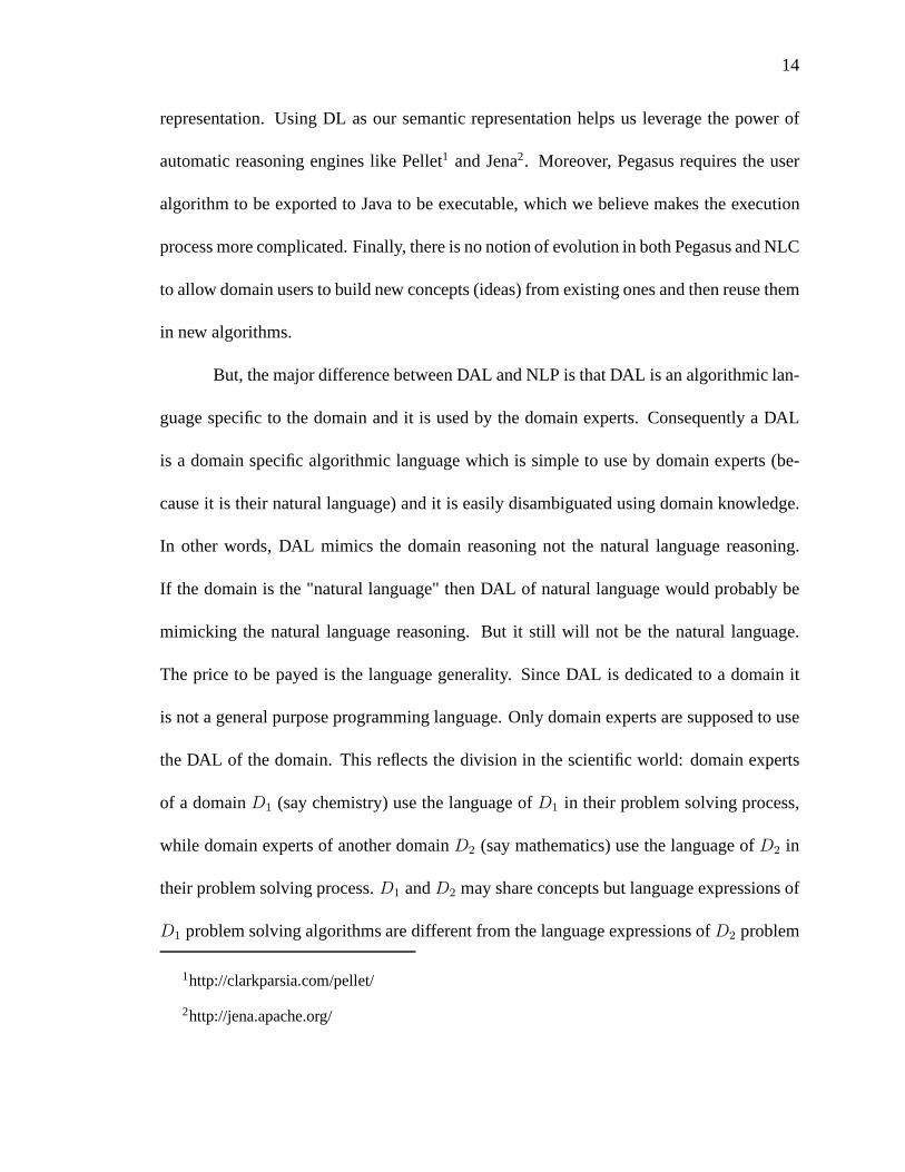
14
representation. Using DL as our semantic representation helps us leverage the power of
automatic reasoning engines like Pellet1 and Jena2. Moreover, Pegasus requires the user
algorithm to be exported to Java to be executable, which we believe makes the execution
process more complicated. Finally, there is no notion of evolution in both Pegasus and NLC
to allow domain users to build new concepts (ideas) from existing ones and then reuse them
in new algorithms.
But, the major difference between DAL and NLP is that DAL is analgorithmic lan-
guage specific to the domain and it is used by the domain experts. Consequently a DAL
is a domain specific algorithmic language which is simple to use by domain experts (be-
cause it is their natural language) and it is easily disambiguated using domain knowledge.
In other words, DAL mimics the domain reasoning not the natural language reasoning.
If the domain is the "natural language" then DAL of natural language would probably be
mimicking the natural language reasoning. But it still willnot be the natural language.
The price to be payed is the language generality. Since DAL isdedicated to a domain it
is not a general purpose programming language. Only domain experts are supposed to use
the DAL of the domain. This reflects the division in the scientific world: domain experts
of a domainD1 (say chemistry) use the language ofD1 in their problem solving process,
while domain experts of another domainD2 (say mathematics) use the language ofD2 in
their problem solving process.D1 andD2 may share concepts but language expressions of
D1 problem solving algorithms are different from the languageexpressions ofD2 problem
1http://clarkparsia.com/pellet/
2http://jena.apache.org/

15
solving algorithms.
2.1.2 Domain Specific Languages
Even though having the the same goal as NLP systems of being more friendly to do-
main users, Domain Specific Languages, unlike languages used in NLP systems, don’t try
to mimic natural languages. They focus on efficient representation and expressive power
for a particular domain. Deursen, Klint & Visser (2000) defined a domain-specific lan-
guage (DSL) as “a programming language or executable specification language that offers,
through appropriate notations and abstractions, expressive power focused on, and usually
restricted to, a particular problem domain”. As you can see,the use of DSLs for problem
solving is not new. According to (Mernik, Heering & Sloane 2005), some of the first DSLs
can be found as early as 1957 and 1959, such as APT (Ross 1978) (developed in 1957),
a DSL for programming numerically-controlled machine tools, or BNF (Backus 1959), a
famous DSL for formal language specification. Since 2000, hundreds of DSLs have been
in existence (Deursen et al. 2000). Some of the well-known examples are LEX, YACC,
Make, SQL, BNF, and HTML. The areas of their domains are extensive. Among them,
Deursen et al. (2000) reported the following groups:
• Software Engineering: Financial products, behavior control, software architectures,
databases.
• System Software: Description and analysis of abstract syntax trees, data structures,
video device driver specification.
• Multimedia: Web Computing, image manipulation, 3D animation.

16
• Telecommunications: String and tree languages for model checking, communication
protocols, etc.
• Others: Simulation, robot control, solving partial differential equations, digital hard-
ware design.
Mernik et al. (2005) showed the design patterns for DSLs, providing guidelines on when
and how to develop DSLs. The need for DSL targeting a specific application domain for
specific platforms has resurfaced over the years. On the scientific domains, new domain
specific languages are still being developed such as Liszt (DeVito, Joubert, Palacios, Oak-
ley, Medina, Barrientos, Elsen, Ham, Aiken, Duraisamy, Darve, Alonso & Hanrahan 2011)
for solving partial differential equations, or BIOLOGO (Cickovski 2004) for cellular and
tissue level morphogenenis modeling.
On the surface, according to Deursen et al. (2000)’s definition of DSL, each DAL
for a particular domain might look like a DSL. However, whileboth DSL and DAL are
intention revealing, there are strong differences betweenDAL and DSL. DSLs are de-
signed with the goal of focusing on a more efficient representation of the problem domain
compared to general purposed programming language. Sometimes they make DSLs look
difficult to understand for domain users. In other words, DSLs help computer experts
handle problem domain concepts rather than helping domain users handle computer tech-
nology. On the other hand, the main goal of our approach is to help domain experts handle
computer technology by bridging the semantic gap between the domain concept and its
implementation.

17
This difference in the design goal leads to the following keydifference in the se-
mantics of DSL and DAL. That is, the vocabulary and semanticsof DSLs are usually fixed
or rarely updated due to committee standardization and longduration processes. After the
computer experts created the language, there is very littleor no direct collaboration be-
tween computer experts and domain users on updating the vocabulary of the DSL. In our
approach, the vocabulary of the DAL continuously evolves toserve the needs of domain
users by adding new concepts to existing vocabulary. Whenever a new primitive domain
concept is added, since DAL is a personal language, it only requires the collaboration be-
tween the domain user and computer expert to formalize and implement the concept. It is
also worth noting that in the current programming paradigmssuch as object oriented pro-
gramming, while it is harder to add primitive concepts than in our approach, it is relatively
easy to compose derivative concepts from the existing concepts.
Another subtle difference between DALs and DSLs is the semantics of each expres-
sion. The meaning of each expression in DSL is strictly defined in the language specifica-
tion. In our approach the meaning of each domain term is defined in the ontology, so the
meaning of each expression depends not only on the language specification but also largely
on the state of the domain ontology.
Finally, since we tend to seek universal, standalone and composable concepts and
store them in the ontology in machine readable format, the concepts identified and created
in our approach can be reused across domains. But programs created by other DSL tend
to be usable only within that language for that particular domain. In other words, while
a DSL is a programming language, a DAL is an algorithmic language, independent of the

18
computer which will execute the DAL algorithms.
These three characteristics also distinguish our approachto domain language from
other general purposed programming languages such as Java,C.
2.2 Web Service Composition
In this thesis, web services were chosen as the execution platform because of their
interoperability across networks. Therefore it is worth examining previous work on lan-
guages for web services composition. Recently as the numberof organizations provid-
ing their services in the form of web services increases, composition of web services
has received more and more interest to support business-to-business integration. There-
fore it is not surprising that the literature on web service composition is extensive (Rao &
Su 2004, Srivastava & Koehler 2003).
In the literature, there are currently two independently main approaches for com-
posing web services: composition using workflows and composition using AI planning. In
the workflow approach, the composition process is mostly done syntactically and manually
using XML standards such as WSDL, SOAP, UDDI, BPEL (Margolis2007). Whereas
in the AI planning approach, web services and their constraints (pre-conditions, post-
conditions) are specified in Semantic Web languages such as DAML-S or OWL-S (Martin
& et al 2003). Then the user only has to specify the goal in the form of a template, the
composition process is done automatically via reasoning techniques by a planning engine.
The workflow approach is preferred in the business world, while the AI planning approach
receives more interest from the academic community.

19
More recently a hybrid approach has appeared, which tries tocombine the strengths
from both worlds (Agarwal, Dasgupta, Karnik, Kumar, Kundu,Mittal & Srivastava 2005).
In this hybrid approach, the composition process is dividedinto two phases: logical com-
position and physical composition. In the logical composition phase, users specify the
composition using workflows. Then during the physical composition phase, a composi-
tion engine applies AI planning techniques to find out the best combination of underlying
web services with respect to some objectives like cost, speed, etc. Our approach for the
DALSystem is closely related to the hybrid approach.
I will review these three approaches in the next sections, especially the hybrid ap-
proach in comparison to our approach.
2.2.1 Web Service Composition using Workflows
This approach is mainly employed in the business world, where carefully planning
and strict security policies are required. A number of XML-based standards such as WSDL,
SOAP, UDDI have been developed over the years to formalize the specification, execution
protocol and registry of web services. There are currently several web services workflow
specification languages, e.g. IBM’s BPEL4WS (Andrews & et al. 2003). Such languages
provide programming-language-like constructs (sequence, branch, loop) for IT experts to
compose web service workflows manually. However such languages are fairly complex,
intended to be used by IT experts (developers) not by domain users like domain scien-
tists. In BPEL4WS programs, domain intention is often buried deeply among irrelevant IT
concepts such as port, signal, messages, etc.

20
The syntax of BPEL4WS is so complex that there are even efforts to make that
syntax less difficult for IT experts such as SimBPEL (Boisvert, Arkin & Riou 2008) and
BPELScript (Bischof, Kopp, van Lessen & Leymann 2009). BPELScript converts the ver-
bose XML syntax of BPEL4WS to a Javascript style language. Even though BPELScript
makes BPEL4WS programs easier to understand for IT experts,such programs are still far
from understandable for domain users. This is because BPELScript follows BPEL4WS
closely to be fully compatible with it.
2.2.2 Web Service Composition using AI Planning
There are efforts from AI community to make the web service composition task
less painful to domain users by automating lower level wiring tasks among web services.
McIlraith & Son (2002) presented a method to automatically compose web services by
applying logical reasoning techniques on a user-predefinedtemplate. In this approach, web
service capabilities are annotated in DAML-S/RDF at first, then compiled into a situation
calculus representation (Narayanan & McIlraith 2002) in Golog, a logical programming
language. The user then inputs her goal as a template into thesystem. For example, a
travel reservation procedure using Golog is shown in Listing 2.2.✞ ☎1 proc ( t r a v e l (D1 , D2 , O, D) ,2 [3 [ bookR A i r t i c ke t (O, D, D1 , D2) ,4 bookCar (D, D, D1 , D2)5 ] |6 bookCar (O, O, D1 , D2) ,7 bookHote l (D, D1 , D2) ,8 sendEmai l ,9 updateExpenseCla im
10 ] ) .

21
✝ ✆Listing 2.2: Travel reservation procedure using Golog. O, D, D1, D2 are Origin,Destination, Departure time, Return Time respectively.
Given the user template, their Golog reasoner evaluates non-deterministic choices and ex-
ecutes the plan on the network using annotated web services.Similar work can be found
in (McDermott 2002). We agree with McIlraith & Son (2002) that ontologies of web ser-
vices should be used to encourage reuse of vocabulary, and shared semantic understanding.
However, there is a difference between our approach and their approach on the philoso-
phy of how to conceptualize the domain ontology. Their approach seems to group existing
web services into common concepts while in our approach, theconcepts are formalized by
domain experts first and then IT experts implement these concepts using web services.
Even though much of the burden on low level IT concepts was taken off of the do-
main user’s shoulders, there are still some problems with this approach. That is, the domain
users now have to use the declarative style of a logical programming language (Golog) to
express their computation. There is a problem aboutclosed world assumptionwith Golog
from a web service composition perspective. That is with truth literals we cannot express
that new information has been acquired (Rao & Su 2004). For example, one service re-
quester might want to say that a new identity number will be generated and returned from a
call to a web service; then will be used during later communication as an ID. Such require-
ments are very common in both business processes and scientific algorithms.

22
2.2.3 Web Service Composition using Hybrid Approach
Agarwal et al. (2005) proposed an integrated system using a hybrid approach to web
services composition, where the composition is divided into two steps: logical composition
and physical composition. In this system, web services are also described formally using
domain-specific terminology in adomain ontology. When the user wants to compose new
services, she writes aservice specificationand provides that toLogical Composermodule.
The Logical Composer will generate an abstract BPEL workflowbased on the information
from the domain ontology. The abstract BPEL workflow will then be passed toPhysi-
cal Composerto generate aconcreteBPEL workflow based on somequantitativecriteria.
While the idea sounds similar to ours, there are some differences between their approach
and our approach. First of all, their service specification language is a general purposed lan-
guage for service composition instead of being domain specific like our approach. It also
seems that there is no data manipulation and data composition in their language. More-
over, their language only supports a limited set of control flows like sequences, branches,
but no loops, while our language is able to handle all typicalcontrol flows including loops.
Finally, there is no clear framework for domain users to evolve automatically the domain
ontology when new composite concepts are added.
Another line of work in the hybrid approach, which is very popular among the sci-
entific community, is implemented in the Grid systems such asPegasus (Deelman, Singh,
hui Su, Blythe, Gil, Kesselman, Mehta, Vahi, Berriman, Good, Laity, Jacob & Katz 2005),
Taverna (Oinn, Addis, Ferris, Marvin, Carver, Pocock & Wipat 2004), Kepler (Altintas,
Berkley, Jaeger, Jones, Ludascher & Mock 2004, Krishnan & Bhatia 2007), Triana (Taylor,

23
Wang, Shields & Majithia 2005), WCT (Gubala, Bubak, Malawski & Rycerz 2006),
ASKALON (Qin & Fahringer 2008), etc. In this group of systems, domain ontologies
are used extensively not only to formalize domain knowledge, but also to support cross-
domain interaction. The use of ontologies also enables the domain users to compose work-
flows at the level of data meaning and action functions (concepts). In some cases (Qin &
Fahringer 2008), ontologies also allow users to semi-automatically compose data flow and
perform automatic data conversion.
The common architecture of these systems consists of:
• a GUI workbench to allow domain scientists to compose workflows in drag-and-drop
manner.
• an intermediate abstract representation language, normally written in the form of
XML such as Sculf (Taverna), AGWL (ASKALON), etc, for these workflows using
the domain concepts in the ontology.
• a workflow mapper will then map the abstract workflow into a concrete executable
representation using the information from the ontology forlooking up available web
services.
• an execution engine, e.g. Freefluo (Taverna), ASKALON runtime system (ASKALON),
will receive the concrete executable representation of theworkflow and run it on the
Grid.
The main difference between these systems and the approach in (Agarwal et al. 2005) lies
in the use of the GUI workbench for designing workflows instead of using textual repre-
sentation, which is supposed to help domain scientists (Scanlan 1989, Kiper, Auernheimer

24
& Ames 1997). Nonetheless, there is also research found thatvisual programming might
not always be more suitable than textual programming (Green& Petre 1992, Petre 1995).
Compared to our approach, these systems still offer a one-size-fits-all solution
for all domains (Curcin & Ghanem 2008), while our approach emphasizes a domain-
specific solution for each domain or group of domains. In other words, our approach brings
intention-revealing style to web service composition. In amore subtle comparison about
the ontology design, most of these workflow systems only focus on the processes (action
concepts) and don’t pay much attention to data concepts. In (Qin & Fahringer 2008), data
concepts receive more attention when the authors separate data concept and data represen-
tation so that the domain users don’t have to worry about lower level representation of their
concepts. However, their approach doesn’t provide mechanisms to compose new data con-
cepts from existing data concepts as in our approach. Moreover, Qin & Fahringer (2008)
seems to mix the domain expert’s view with the IT expert’s view about domain concepts in
a single ontology level which leads to an inconsistent ontology. In our approach, these two
different views are separated clearly into two ontology levels.
Furthermore, only Taverna (Oinn et al. 2004) provides a clear mechanism and tools
for the user to share Sculf workflows among scientists as web services. However Tav-
erna doesn’t automatically import the concept associatingwith the workflow into the user’s
ontology like in our approach for ontology evolution.
Finally my research is part of a bigger theme of developing software for non-expert
computer users proposed by Rus (2008). This research focuses on the development of ab-
stractions that liberate computer users from programming.This means that we advocate

25
the creation of languages dedicated to the problem solving process in the problem domain,
not necessarily to program development using conventionalprogramming languages. Pre-
vious experiments reported in (Rus & Curtis 2006, Rus & Curtis 2007, Curtis, Rus &
Jensen 2008, Rus & Bui 2010) provided software tools based ondistributed process execu-
tion under the Unix system. My PhD thesis contributes to thisresearch by
• using a domain ontology to formalize a subset of the arithmetic domain,
• implementing a DAL for the arithmetic domain,
• implementing a stack-based domain dedicated virtual machine (DDVM) (Rus 2013)
executing on web services,
• providing a mechanism for domain users to evolve their ontology,
in the DALSystem as a proof of concept.

26
CHAPTER 3PROCESS OF DEFINING DOMAIN ONTOLOGY
Using ontologies to formalize domain concepts is by no meansnew. However,
much of the current work on ontologies focuses on development and modeling (Welty &
Guarino 2001, Gasevic et al. 2009). This thesis, on the otherhand, concentrates on structur-
ing domain ontologies to support the automation of concept execution using web services
and concept evolution including action concepts and data concepts in a process called Com-
putational Emancipation of Application Domain (CEAD) (Rus2008). In addition, there is
also research on using ontologies for web services composition in scientific workflows such
as (Qin & Fahringer 2008, Altintas et al. 2004). As discussedin chapter 2, their approach
seems to mix domain expert view and IT expert view of domain concepts in a single on-
tology level, while we separate these two often different views into two complementary
ontology levels, i.e.pure domain ontologyfor domain expert’s view and CEAD-ed domain
ontology for IT expert’s view.
Therefore in this chapter I will briefly discuss the method that we use to formalize
a domain vocabulary in a pure domain ontology. Then I focus ondiscussing our meta-
ontology, called CEADOntology, which facilitates the association of each concept in the
domain ontology with computational artifacts implementing it. The purpose of this process
is to increase the efficiency of executing DAL algorithms by automating the process of
searching for web services in the CEADOntology file named OWL(DAL) and evaluating
them.

27
3.1 Domain Ontology
Ontology is a discipline of philosophy dealing with object existence, structures,
properties and their relationships. The philosophical work can be traced back to Aristo-
tle in the form of metaphysics. However, the termontologywas believed to be coined by
Rudof Gockel in 1963 (Welty & Guarino 2001). Ontology found its way to computer sci-
ence in the early 1980s when AI researchers realized the importance of work in ontology
for knowledge representation (McCarthy 1980). The term became a buzzword in knowl-
edge management and enterprise modeling, where “knowledgesharing” and interchange is
emphasized.
In this thesis, ontology is used to conceptualize the vocabulary of a problem domain
in the CEAD process. It is the first step of the CEAD process where domain ontology is
developed by domain experts by gathering domain terms, their properties and relationships.
We found that OntoClean (Welty & Guarino 2001) is an efficientmethodology for ontology
development. OntoClean helps domain experts build domain ontologies by analyzing tax-
onomies to formwell-foundedones, calledbackbone taxonomies. A backbone taxonomy
consists of only rigid concepts, which are divided into three kinds: categories, typesand
quasi-types. This backbone taxonomy is specified by a collection of disjoint trees whose
nodes are primitive concepts of the domain and whose edges are relationships interpreted
as logical subsumptions, i.e., if conceptC1 subsumes conceptC2 then∀x.C1(x)→ C2(x).
After constructing the backbone taxonomy, domain experts can add other kinds of con-
cepts such asattributionsandformal roleswhich can be combined with primitive concepts
in the backbone taxonomy to form lower level concepts such asmixinsandmaterial roles.

28
Such additional concepts transform the backbone tree to a directed acyclic graph (DAG).
Figure 1.1 shows an example ontology for the arithmetic domain.
We choose to use Description Logics (DL) (Baader et al. 2007)as the formal speci-
fication of ontologies via Web Ontology Language (OWL). In DL, problem domain termi-
nologies can be captured using the following important types of entities:concept, role and
individual. For a given domain we have a collection of termsC = {c1, c2, . . .} representing
basicconceptsof the domain, a set of relations (calledroles) R = {R1, R2, . . .} represent-
ing fundamental properties of domain concepts, and a set of individualsI = {i1, i2, . . .}
representing instances of concepts in the domain. The set-theoretic model of DL allows us
to reason about domain objects. The above example ontology for the arithmetic domain in
Figure 1.1 is represented in DL using the OWL language as shown in Listing 3.1.
In our approach, the domain ontology modeling the problem solving process con-
sists of two parts: a part that represents the user own ontology (UOO) and a part that
represents the domain expert ontology (DEO). The domain expert ontology is built by do-
main experts using a small taxonomy chosen from a textbook. This ontology is the result
of the collaboration between the domain expert and the computer expert as follows:
1. Domain expert defines terms, declares axioms and subsumeshierarchy.
2. Computer expert constructs OWL files from the terms given by the domain expert.
Protege can be used to create and edit OWL files.
The User Own Ontology (UOO) is built by extending the DEO. Initially, the UOO is the
same as the DEO. Then, during the problem solving process, the UOO is automatically
evolved with new concepts representing problems and solution algorithms developed by

29
✞ ☎1 <?xml v e r s i o n =" 1 . 0 " ?>2 < r d f :RDF3 xmlns : r d f =" h t t p : / / www. w3 . org /1999/02/22− rd f−syntax−ns # "4 xmlns : xsd=" h t t p : / / www. w3 . org / 2 0 0 1 / XMLSchema# "5 xmlns : r d f s =" h t t p : / / www. w3 . org / 2 0 0 0 / 0 1 / rd f−schema # "6 xmlns : owl=" h t t p : / / www. w3 . org / 2 0 0 2 / 0 7 / owl# "7 xmlns =" h t t p : / / bu la1 . cs . uiowa . edu / o n t o l o g i e s / a r i t h me t i c s . owl# "8 xml : base =" h t t p : / / bu la1 . cs . uiowa . edu / o n t o l o g i e s / a r it h m e t i c s . owl "
>9
10 <!−− Numbers−−>11 <owl : C l a s s r d f : ID=" Number " / >12 <owl : C l a s s r d f : ID=" Complex ">13 < r d f s : subClassOf r d f : r e s o u r c e =" #Number " / >14 </ owl : C lass >15 <owl : C l a s s r d f : ID=" Real ">16 < r d f s : subClassOf r d f : r e s o u r c e =" #Complex " / >17 </ owl : C lass >18 <owl : C l a s s r d f : ID=" R a t i o n a l ">19 < r d f s : subClassOf r d f : r e s o u r c e =" # Real " / >20 </ owl : C lass >21 <owl : C l a s s r d f : ID=" I r r a t i o n a l ">22 < r d f s : subClassOf r d f : r e s o u r c e =" # Real " / >23 </ owl : C lass >24 <owl : C l a s s r d f : ID=" I n t e g e r ">25 < r d f s : subClassOf r d f : r e s o u r c e =" # R a t i o n a l " / >26 </ owl : C lass >2728 <!−− Opera to rs −−>29 <owl : C l a s s r d f : ID=" O pe r a t o r " / >30 <owl : C l a s s r d f : ID=" Unary ">31 < r d f s : subClassOf r d f : r e s o u r c e =" # O pe r a t o r " / >32 </ owl : C lass >33 <owl : C l a s s r d f : ID=" B inary ">34 < r d f s : subClassOf r d f : r e s o u r c e =" # O pe r a t o r " / >35 </ owl : C lass >3637 <Unary r d f : ID=" u n a r y S u b t r a c t " / >38 <Unary r d f : ID=" f a c t o r i a l " / >39 < Binary r d f : ID=" addI " / >40 < Binary r d f : ID=" s u b t r a c t I " / >41 < Binary r d f : ID=" m u l t i p l y I " / >42 < Binary r d f : ID=" d i v i d e I " / >43 </ r d f : RDF>✝ ✆
Listing 3.1: OWL file for arithmetic ontology in Figure 1.1
30
a particular computer user. Thus the user’s ontology space at any given time consists of
the core DEO-s, that is commonly available to all the users, and a private part (UOO),
which is specific to a given user. The domain expert ontology can also evolve by adding
new concepts and importing useful concepts from private ontologies of domain users. The
domain evolving process will be discussed later in Chapter 7.
3.2 CEAD Ontology
In this section, I will discuss our meta-ontology, called CEAD ontology, which fa-
cilitates the process of associating a problem domain concept with its corresponding com-
putation artifacts. Figure 3.1 shows the overview of this ontology. CEAD ontology can
be seen as the complementary view of computer experts to the domain concepts. In other
words, this ontology serves as the bridge between the domainconcepts and computational
artifacts implementing them. There is an important observation here; that is, not all do-
main concepts have computational meaning. Moreover, thereare also concepts in CEAD
ontology that are strictly for supporting implementation,which should not be of concern
to domain experts. In our approach, to capture the computational essence of a domain
ontology, we have developed two main concepts in this meta-ontology: DataConceptand
ActionConceptwhich are described as follows.
DataConceptis the class of data concepts in a problem domain for example
ari:Integer, ari:Real, ari:Complex, etc. in the arithmetic domain. It provides
general description for domain data concepts.DataConceptclass has two subclasses,Prim-
itiveDataConceptandDefinedDataConcept. PrimitiveDataConceptclass consists of data

31
ActionConcept
FilterConcept
Agent SerivceInstance
DataConcept
PrimitiveDataConceptDefinedDataConcept
ComposedDataConcept UnconstrainedArray
ConstrainedArray
Input
Output
hasInput
hasOutput
hasAgent
implementedBy
hasType
hasType
Figure 3.1: Overview of CEAD Ontology

32
ComposedDataConcept FieldhasField
1 n
DataConcept
hasType
UnconstrainedArrayhasBaseType
castable
Figure 3.2: Object properties among CEAD concepts for data modeling
elements that have direct XML data types implementing them.For example,ari:Integer
andari:Real can be represented byxsd:int andxsd:double, respectively. On the
other hand,DefinedDataConceptclass contains data concepts that have no direct represen-
tation and are defined via other data concepts. For instance,ari:Complex can be seen as
a data concept composed of twoari:Real numbers. One is the real component and the
other is the imaginary component of that complex number. There are two types ofDefined-
DataConcept, i.e. ComposedDataConceptandUnconstrainedArray. EachComposedDat-
aConcepthas a number ofField-s, represented by the propertyhasField. EachField has
its type, aDataConcept, represented by the propertyhasType. TheUnconstrainedArrayis
used to model a data concept which is an array (or a list) of elements of another data con-
cept. EachUnconstrainedArrayhas a type for its elements ofDataConcept, represented
by the propertyhasBaseType. The relationships among these classes of concepts via their

33
object properties1 are shown in Figure 3.2.
On the action side,ActionConceptis used to model action concepts in a problem
domain. An action concept models an agent which performs some computation and trans-
forms its input (data concept) into an output (also a data concept). The relationships among
CEAD concepts that facilitate domain action concepts are shown in Figure 3.1. EachAc-
tionConcepthas a number ofInput-s, represented by the propertyhasInput. The output of
anActionConceptis represented by the propertyhasOutput. Both Input andOutputhave
their types asDataConcept-s, represented by the propertyhasType. EachActionConcept
has an agent to manage its computation artifacts which areServiceInstance-s in this case.
These relationships are represented by the propertieshasAgent, implementedBy. Finally,
FilterConceptis a subclass of theActionConceptwhich converts one data concept to an-
other. The following SPARQL (DuCharme 2011) reasoning rules reflects the relationship
betweenFilter andDataConcept.✞ ☎1 [ r u l e 1 : ( ? a r d f :type cead : F i l t e r C o n c e p t ) ( ? a cead : h a s I n p u t ?b )2 ( ? b cead : inpu tType ? c ) ( ? a cead : hasOutpu t ?d )3 −> ( ? c cead : c a s t a b l e ?d ) ]45 [ r u l e 2 : ( ? a cead : c a s t a b l e ?b ) ( ? b cead : c a s t a b l e ? c )6 −> ( ? a cead : c a s t a b l e ? c ) ]✝ ✆
Listing 3.2: Reasoning rules aboutcastableproperty
These rules say that a typeA is castable to a typeB if there exists a filter with the input of
typeA and the output is typeB. This castable property is also transitive. This means that
if A is castable toB, B is castable toC, thenA is castable toC. These reasoning rules
are used by DALTranslator in section 6.1.5 and section 6.1.3to find out if one type of data
1http://www.w3.org/TR/owl-features/

34
Data Properties XSD Type Description
DataConceptdataType xs:anyURI the URI of XSD type representing this data
conceptConstrainedArrayhasLowerBound xs:int lower bound for a constrained arrayhasUpperBound xs:int upper bound for a constrained arrayInputinputName xs:string name of the input parameterorder xs:int position of the input parameter in the input
listServinceInstanceserviceName xs:string name of the web servicewsdlFile xs:string URI of the WSDL file of the web serviceoperationName xs:string name of the corresponding operation which
performs the action conceptportName xs:string name of the port on the web service
mentioned in the WSDL file
Table 3.1: Data properties for CEAD concepts
concept can be castable to another type of data concept during the process of disambiguat-
ing DAL concepts in DAL expressions. Finally, table 3.1 shows data properties of CEAD
concepts. The whole OWL file defining CEAD Ontology is shown inAppendix B.
3.3 Associating Domain Concepts with Web Services
Using the CEAD ontology, an IT expert can work with a domain expert to associate
domain concepts with their computational artifacts. The ITexpert should start with helping

35
the domain expert identify data concepts and action concepts2. Data concepts represent data
that can be used in a computational process such as the input and output of such a process.
Computational processes are represented as action concepts. Data concepts are associated
with XML Schema data types via the propertydataType. For example, theInteger
concept is associated withXSD:int3 type, i.e.IntegerdataType−→ URI(xsd:int). An OWL
excerpt forInteger definition is shown in Listing 3.3.✞ ☎1 <cead : DataConcept r d f : abou t =" # I n t e g e r ">2 < r d f : type r d f : r e s o u r c e =" h t t p : / / www. w3 . org / 2 0 0 2 / 0 7 / owl# C l a s s "
/ >3 <cead : d e s c r i p t i o n > I n t e g e r concep tof a r i t h m e t i c s domain </
cead : d e s c r i p t i o n >4 <cead : dataType >5 xsd : i n t6 </ cead : dataType >7 </ cead : DataConcept >✝ ✆
Listing 3.3: Data conceptInteger definition in OWL
The CEAD process associates action concepts such asadd, subtract, multiply,
etc., with web services which implement them via a Concept Agent. There could be several
web services instances that implement the same concept so that if one instance is unavail-
able, other instances can take over its responsibility. Forexample, the conceptadd may
have the agentaddAgent implemented by two web service instances:addInstance1,
addInstance2, whereaddInstance1’s properties are populated in Table 3.1. The
agent maintains a list of web services which it can execute asimplementations of the ac-
tion it performs. The RDF triples that define an action concept X follows the pattern:
2As discussed previously, there might be concepts in the domain ontology which have no com-putational meaning thus cannot be categorized as either data concept or action concept.
3http://www.w3.org/2001/XMLSchema#int

36
Data Properties Value
ServinceInstanceserviceName CalculatorImplServicewsdlFile http://bula1.cs.uiowa.edu:8282/
CalculatorImplService/CalculatorImpl?wsdloperationName addNumbersportName CalculatorImplPort
Table 3.2: addInstance1 properties
XhasAgent−→ aAgent andaAgent
implementedBy−→ aInstance1; . . .; aAgent
implementedBy−→
aInstanceN. For example, theadd concept is represented by the following RDF triples:
addhasAgent−→ addAgent,addAgent
implementedBy−→ addInstance1. The input and out-
put relation between action concepts and data concepts are represented by the properties
hasInput, hasOutput. For example:addhasInput−→ Integer,
addhasOutput−→ Integer. The representation of these relations are expressed in theOWL
language as shown in Listing 3.4.
3.4 Discussion
Pure domain ontology reflects how domain experts see the world. It could be very
different from IT experts’ view of that world. For example, in the arithmetic domain, a
mathematician sees the relationship betweenComplex andReal as a subsumption. On
the other hand, a computer expert sees bothComplex andReal as instances of the meta-
classDataConcept where an instance ofComplex is a record of twoReal numbers,
while Real is a primitive concept. So obviously an instance ofReal is not a record, thus

37
✞ ☎1 <cead : Act ionConcep t r d f : abou t =" #add ">2 <cead : d e s c r i p t i o n > Thisi s t he add o p e r a t i o n i n t he
a r i t h m e t i c s domain .3 I t t a k e s two i n t e g e r sand re tu rn t he sum of them .4 </ cead : d e s c r i p t i o n >5 < r d f : type r d f : r e s o u r c e =" h t t p : / / www. w3 . org / 2 0 0 2 / 0 7 / owl# C l a s s "
/ >6 <cead : has Inpu t >7 <cead : I npu t r d f : ID = " addI1 ">8 <cead : inpu tType r d f : r e s o u r c e =" # I n t e g e r " / >9 <cead : o rde r >1 </ cead : o rde r >
10 </ cead : Inpu t >11 </ cead : has Inpu t >12 <cead : has Inpu t >13 <cead : I npu t r d f : ID = " addI2 ">14 <cead : inpu tType r d f : r e s o u r c e =" # I n t e g e r " / >15 <cead : o rde r >2 </ cead : o rde r >16 </ cead : Inpu t >17 </ cead : has Inpu t >18 <cead : hasOutpu t r d f : r e s o u r c e =" # I n t e g e r " / >19 <cead : hasAgent >20 <cead : Agent r d f : ID=" addAgent ">21 <cead : implementedBy r d f : r e s o u r c e =" # a d d S e r v i c e I n s t an c e 1 "
/ >22 </ cead : Agent >23 </ cead : hasAgent >24 </ cead : Act ionConcept >25 <cead : S e r v i c e I n s t a n c e r d f : ID=" a d d S e r v i c e I n s t a n c e 1 ">26 <cead : w s d l F i l e r d f : d a t a t y p e =" h t t p : / / www. w3 . org / 2 0 01 /
XMLSchema# s t r i n g ">27 h t t p : / / bu la1 . cs . uiowa . edu : 8 2 8 2 / C a l c u l a t o r I m p l S e r vi c e /
C a l c u l a t o r I m p l ? wsdl28 </ cead : wsd lF i l e >29 <cead : serv iceName r d f : d a t a t y p e =" h t t p : / / www. w3 . org /2 0 0 1 /
XMLSchema# s t r i n g ">30 C a l c u l a t o r I m p l S e r v i c e31 </ cead : serv iceName >32 <cead : opera t ionName r d f : d a t a t y p e =" h t t p : / / www. w3 . org / 2 0 0 1 /
XMLSchema# s t r i n g ">33 addNumbers34 </ cead : operat ionName >35 <cead : portName r d f : d a t a t y p e =" h t t p : / / www. w3 . org / 2 0 01 /
XMLSchema# s t r i n g ">36 C a l c u l a t o r I m p l P o r t37 </ cead : portName >38 </ cead : S e r v i c e I n s t a n c e >✝ ✆
Listing 3.4: Action conceptadd definition in OWL

38
it cannot be an instance ofComplex. ThusComplex does not subsumeReal, which
contradicts the mathematician’s view about the relationship betweenComplex andReal.
How is importing ontologies different from importing programming libraries? First
of all, the user does not have to install the libraries on her system. The user also does
not have to care about where the program is running and the service providers don’t have
to deploy their code to the user system. These two propertiesof this model encourage
sharing computation resources and knowledge in a competitive environment, which is very
important in scientific research communities. Of course, the trade-off for this simplicity
in deployment and sharing is the performance. Importing programming libraries into the
user’s local system offers much better performance since all of the communication happens
in the system bus. However, as the speed of the Web becomes faster and faster, this trade-off
might not be a problem for most domain users.
Finally, the use of ontology to formalize a domain allows domain users to perform
not only syntactic but also semantic searches for the concepts they need. This is very im-
portant for the knowledge discovery process since it allowsa higher level of expressiveness
and gives the user more powerful tools to specify her intent.

39
CHAPTER 4DOMAIN ALGORITHMIC LANGUAGE
Given the domain ontology with concepts associated with their computational arti-
facts, i.e. XML data types or web services, domain users can use these concepts for their
computation or compose new concepts using the workflow approach as reported in (Qin &
Fahringer 2008, Altintas et al. 2004, Gubala et al. 2006)1. Even though such logical compo-
sition approaches are better than low-level workflow compositions like BPEL4WS, they are
still general purposed tools for workflow composition. Therefore they provide inefficient
and unnatural manners to the domain users to express their computation solutions.
In this chapter, I will discuss our approach to the computational language of a prob-
lem domain. This language allows domain users to express their computations naturally
using terms of their domain without worrying about the representations of these terms in
the underlying computer system. We call such language a domain algorithmic language
(DAL), where its vocabulary and phrases are characteristicto the domain and domain users
can understand it without much explanation. Although this thesis has no ambition of pro-
viding a methodology for synthesizing computational languages for all the domains, I still
want to present some design guidelines for such languages, based on my experience from
working with the domain of arithmetic.
Before further discussion of the design guidelines of theselanguages, I would like
to clarify our assumptions. The main assumption is that solvable problems of any problem
1These approaches are equivalent to our lower level language, called SADL, executed by avirtual machine discussed in Chapter 5

40
domain are expressible in terms of a finite number of well defined concepts. We assume
further that these well defined concepts are formalized in a domain ontology as discussed
in Chapter 3.
Given the above assumptions, the following guidelines can be used to capture a
DAL specification:
1. identify characteristic concepts that are primitive data concepts in the domain ontol-
ogy and build the lexical rules for such concepts. These concepts are the building
blocks of the language. For example, in the arithmetic domain,Integer, Real are
primitive data concepts.
2. identify the rules that combine these basic building blocks to form larger language
expressions such as phrases, sentences. These are the second level formation rules,
for example, expressions like1 + 2, (a− b)× c.
3. identify rules that combine the phrases and sentences to form meaningful solutions to
problems, i.e. the discourse level formation rules. Such rules often involve sentences
concatenation, choice, anditeration.
4. use a dictionary to provide the link between the domain terms and their meanings
in the ontology. The dictionary also helps to reduce the level of ambiguity in the
language.
The language should also exploit domain knowledge represented in domain ontology in the
forms of subsumption and other kinds of relations for concepts disambiguation.
From the fact that current computer language technology hasbeen providing domain-
specific language solutions for hundreds of domains, I believe that most of the domain al-

41
gorithmic languages can also be handled by conventional language construction tools. As
a demonstration, I will show a specification for a DAL of the arithmetic domain in the
following sections.
4.1 Examples of DAL(D)
This section shows some examples of DAL for several related domains such as
arithmetic, high school algebra, and linear algebra. In each domain, DAL vocabulary,
some constructs and discourses are demonstrated.
4.1.1 A DAL for Arithmetic Domain
Vocabulary: The vocabulary for a simple arithmetic domain can consist of: integer,
real, add, subtract, multiply, divide, mod,+,−, ∗, /,%.
Constructs: Some basic constructs are arithmetic expressions as follows: 1 + 2,
3 ∗ 4, etc.
Discourse: An interesting discourse (multiple statements) in the arithmetic domain
is the Euclidean algorithm to find the greatest common divisor (gcd) of two integers.✞ ☎1 concep t : " gcd " ;2 d e s c r i p t i o n : " Th is f u n c t i o n f i n d s t he g r e a t e s t common d i vi s o r (
gcd ) o f two i n t e g e r s us i ng E uc l i de a n a l g o r i t h m . " ;3 i n p u t : a : i n t e g e r , b : i n t e g e r ;4 o u t p u t : c : i n t e g e r ;5 l o c a l : t : i n t e g e r ;67 whi le b != 0 do8 t = b ;9 b = a % b ;
10 a = t ;11 endwhi le ;12 c = a ;✝ ✆
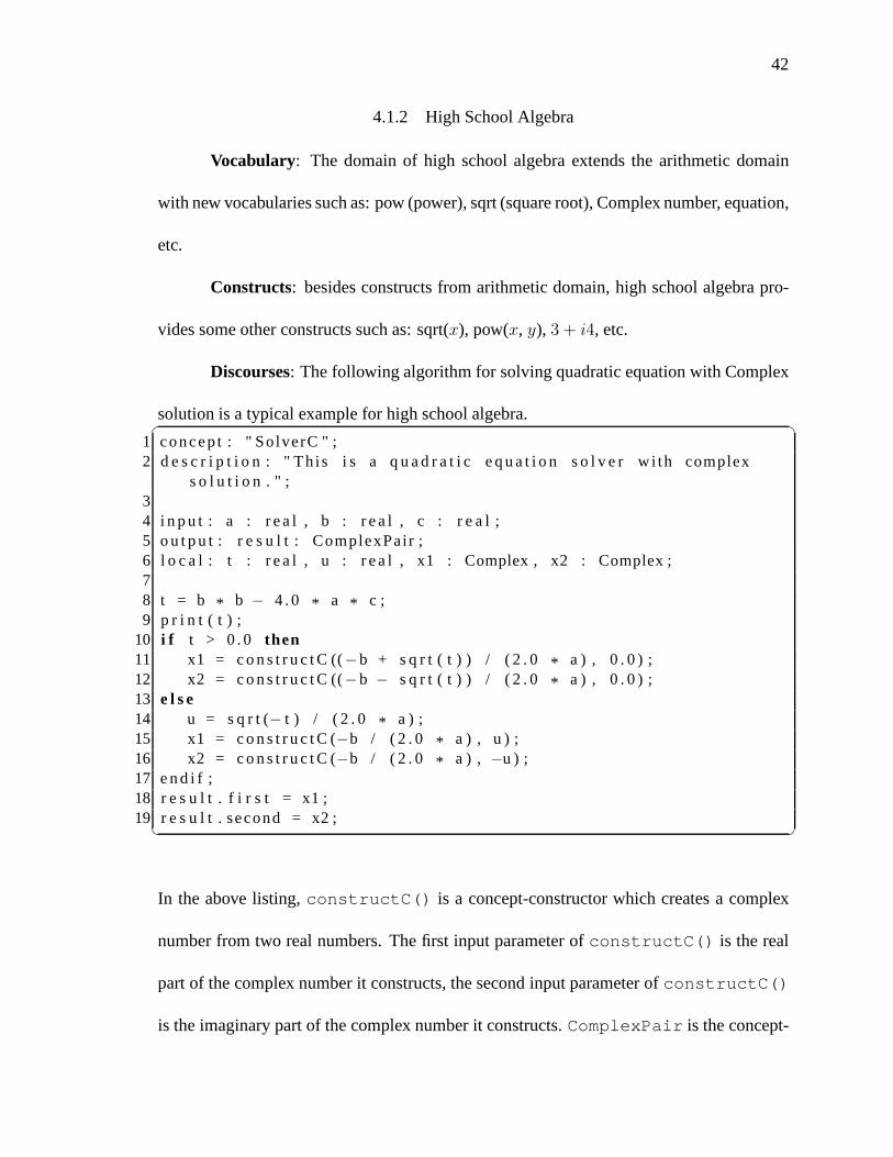
42
4.1.2 High School Algebra
Vocabulary: The domain of high school algebra extends the arithmetic domain
with new vocabularies such as: pow (power), sqrt (square root), Complex number, equation,
etc.
Constructs: besides constructs from arithmetic domain, high school algebra pro-
vides some other constructs such as: sqrt(x), pow(x, y), 3 + i4, etc.
Discourses: The following algorithm for solving quadratic equation with Complex
solution is a typical example for high school algebra.✞ ☎1 concep t : " SolverC " ;2 d e s c r i p t i o n : " Th is i s a q u a d r a t i c e q u a t i o n s o l v e r w i th complex
s o l u t i o n . " ;34 i n p u t : a : r e a l , b : r e a l , c : r e a l ;5 o u t p u t : r e s u l t : ComplexPair ;6 l o c a l : t : r e a l , u : r e a l , x1 : Complex , x2 : Complex ;78 t = b * b − 4 . 0 * a * c ;9 p r i n t ( t ) ;
10 i f t > 0 . 0 then11 x1 = c o n s t r u c t C ((−b + s q r t ( t ) ) / ( 2 . 0 * a ) , 0 . 0 ) ;12 x2 = c o n s t r u c t C ((−b − s q r t ( t ) ) / ( 2 . 0 * a ) , 0 . 0 ) ;13 e l s e14 u = s q r t (− t ) / ( 2 . 0 * a ) ;15 x1 = c o n s t r u c t C (−b / ( 2 . 0 * a ) , u ) ;16 x2 = c o n s t r u c t C (−b / ( 2 . 0 * a ) , −u ) ;17 e n d i f ;18 r e s u l t . f i r s t = x1 ;19 r e s u l t . second = x2 ;✝ ✆
In the above listing,constructC() is a concept-constructor which creates a complex
number from two real numbers. The first input parameter ofconstructC() is the real
part of the complex number it constructs, the second input parameter ofconstructC()
is the imaginary part of the complex number it constructs.ComplexPair is the concept-

43
constructor of a pair of two complex numbers.
4.1.3 Linear Algebra
Vocabulary: The linear algebra domain extends the arithmetic domain ina different
direction than the high school algebra domain. In this domain, new vocabularies are vector,
matrix, linear equation system, and solution.
Constructs: v[1] = 10, v[1] − v[2], v1 ∗ v2, m[1][2]/m[1][1], wherev, v1, v2 are
vectors,m is a matrix.v[i] means thei-th element of a vector,m[i][j] means the element
of i-th row atj-th column.
Discourse: A typical algorithm in the domain of linear algebra is to compute scalar
product of two vectors. It is shown in the following listing:✞ ☎1 concep t : " p r oduc t " ;2 d e s c r i p t i o n : " Compute s c a l a r p r oduc t o f two v e c t o r s . " ;3 i n p u t : a : Vector , b : Vector , n : i n t e g e r ;4 o u t p u t : c : r e a l ;5 l o c a l : k : i n t e g e r ;67 c = 0 . 0 ;8 f o r k = 1 ; i f k <= n9 begin
10 c = c + a [ k ] * b [ k ] ;11 end12 wi thNext k = k + 1 ;✝ ✆
4.1.4 User Dictionary
A user dictionary is where domain terms and their semantics are glued together.
Its purpose is very similar to a normal dictionary except forthe fact that the meaning of
each term is defined by the URI of the corresponding ontological concept in the domain

44
ontology. The user dictionary is stored in a file which contains the list of entries, one entry
for each primitive concept. Each entry has three componentsseparated by a comma “,”.
They are:
1. wordForm: the term that the domain expert used to denote the concept.
2. category: it could be noun (N) for a data concept, verb (V) for an action concept,
adjective (A) for an action concept with the returned value of type boolean.
3. URI: the URI of the concept that the user refers to.
A sample dictionary for arithmetic domain is shown in Listing 4.1. The dictionary is used
by the DAL Translator during the semantic annotion process after a DAL expression was
parsed. During the semantic annotation process each domainterm is mapped to its cor-
responding domain concept based on the dictionary entries.A more detailed discussion
about this annotation process is provided in chapter 6.
4.2 DAL Specification for Arithmetic Domain
Formally a DAL can be specified using a pattern similar to the pattern used to spec-
ify computer languages, which consists of a finite set of BNF rules, specifying terms de-
noting domain characteristic concepts, and few simple BNF rules for statement formation.
Further, the DAL specification mechanism should allow both its vocabulary and formation
rules to grow dynamically with the domain learning process.We call this the process of
DAL’s evolution. This allows the domain experts to freely reuse new concepts and solution
algorithms as components of the new concepts and solution algorithms developed during
the problem solving process.

45
✞ ☎1 i n t e g e r ,N, h t t p : / / bu la1 . cs . uiowa . edu / owl / a r i t h m e t i c. owl# I n t e g e r2 r e a l ,N, h t t p : / / bu la1 . cs . uiowa . edu / owl / a r i t h m e t i c . owl# Real3 s q r t ,V, h t t p : / / bu la1 . cs . uiowa . edu / owl / a r i t h m e t i c . owl# s q r t4 + ,V, h t t p : / / bu la1 . cs . uiowa . edu / owl / a r i t h m e t i c . owl#add5 + ,V, h t t p : / / bu la1 . cs . uiowa . edu / owl / a r i t h m e t i c . owl#addR6 * ,V, h t t p : / / bu la1 . cs . uiowa . edu / owl / a r i t h m e t i c . owl# m u lt i p l y7 * ,V, h t t p : / / bu la1 . cs . uiowa . edu / owl / a r i t h m e t i c . owl# mu lt i p l yR8 −,V, h t t p : / / bu la1 . cs . uiowa . edu / owl / a r i t h m e t i c . owl# s u bt r a c t9 −,V, h t t p : / / bu la1 . cs . uiowa . edu / owl / a r i t h m e t i c . owl# s u bt r a c t R
10 −,V, h t t p : / / bu la1 . cs . uiowa . edu / owl / a r i t h m e t i c . owl# u n ar y S u b t r a c t11 −,V, h t t p : / / bu la1 . cs . uiowa . edu / owl / a r i t h m e t i c . owl# unar yS ub t r a c t R12 / ,V, h t t p : / / bu la1 . cs . uiowa . edu / owl / a r i t h m e t i c . owl#d i v i d e13 / ,V, h t t p : / / bu la1 . cs . uiowa . edu / owl / a r i t h m e t i c . owl#d iv ideR14 %,V, h t t p : / / bu la1 . cs . uiowa . edu / owl / a r i t h m e t i c . owl#modI15 > ,A, h t t p : / / bu la1 . cs . uiowa . edu / owl / a r i t h m e t i c . owl#g r e a t e r T ha n16 > ,A, h t t p : / / bu la1 . cs . uiowa . edu / owl / a r i t h m e t i c . owl#grea te rThanR17 < ,A, h t t p : / / bu la1 . cs . uiowa . edu / owl / a r i t h m e t i c . owl#l e s s T ha n18 < ,A, h t t p : / / bu la1 . cs . uiowa . edu / owl / a r i t h m e t i c . owl#lessThanR19 <= ,A, h t t p : / / bu la1 . cs . uiowa . edu / owl / a r i t h m e t i c . owl# lessThanOrEqua l20 == ,A, h t t p : / / bu la1 . cs . uiowa . edu / owl / a r i t h m e t i c . owl# e q u a l I21 != ,A, h t t p : / / bu la1 . cs . uiowa . edu / owl / a r i t h m e t i c . owl# no t E qua l I22 not ,A, h t t p : / / bu la1 . cs . uiowa . edu / owl / a r i t h m e t i c . owl#notOp23 and ,A, h t t p : / / bu la1 . cs . uiowa . edu / owl / a r i t h m e t i c . owl#andOp24 or ,A, h t t p : / / bu la1 . cs . uiowa . edu / owl / a r i t h m e t i c . owl#orOp25 s t r i n g a r r a y ,N, h t t p : / / bu la1 . cs . uiowa . edu / owl / cead .owl# S t r i n g A r r a y26 s t r i n g ,N, h t t p : / / bu la1 . cs . uiowa . edu / owl / cead . owl# St r i n g✝ ✆
Listing 4.1: Dictionary entries for Arithmetic Domain

46
4.2.1 Rule Representation
Grammar rules for DAL are written in Backus-Naur Form (BNF) form (Backus
1959), except for some lexical rules which are written in theJFlex2 style for specifying
regular expressions.
4.2.1.1 Characters
DAL use ASCII charset with the following special character classes:✞ ☎1 NONNEWLINE_WHITE_SPACE_CHAR = [ \ \ t \ b \ 012 ]2 NEWLINE=\ r | \ n | \ r \ n3 WHITE_SPACE_CHAR= [ \ n \ r \ \ t \ b \ 012 ]✝ ✆
4.2.2 Lexical elements
Comments: every line starts with “#” is considered a comment and ignored during
the parsing process.
Semicolons: Every statement ends with a semicolon “;”.
Identifiers: Identifiers name algorithm entities such as variables and concepts (types).
An identifier is a sequence of one or more letters and digits. The first character must be a
letter.✞ ☎1 IDENTIFIER = [ a−zA−Z ] ( [ a−zA−Z0−9]* )✝ ✆
Keywords: The following keywords are reserved and should not be used as identi-
fiers.
2Available at http://jflex.de/

47
array endconcept import message returnbegin endif input not thendescription endrecord is of vocabularydo endwhile local ontology whileelse for localURI output withNextend if loop record
Operators and Delimiters: The following character sequences represent opera-
tors, delimiters, etc.
+ = != ( )- < <= [ ]* > >= { }/ == .. , ;% ! . :
Integer Literals : An integer literal is a sequence of digits representing an integer
constant.✞ ☎1 DEC_INT_LITERAL = 0 | [1−9][0−9]*✝ ✆
Floating-point Literals: A floating-point literal is a decimal representation of a
floating-point real constant.✞ ☎1 FLOAT_LITERAL = ( { FL i t1 } | { FL i t2 } ) { Exponent } ?23 FL i t1 = [0−9]+ \ . [0−9]*4 FL i t2 = \ . [0−9]+5 Exponent = [ eE ] [+−]? [0−9]+✝ ✆
String Literals : A string literal represents a string constant.✞ ☎1 STRING_TEXT= ( \ \ \ " | [ ^ \ n \ r \ " ] | \ \ { WHITE_SPACE_CHAR } + \\ ) *✝ ✆

48
4.2.3 Declarations
Variable Declarations: A variable declaration creates a variable, binds an identifier
to it and gives it a type.✞ ☎1 var_dec_cmd : : = IDENTIFIER : name " : " IDENTIFIER :type✝ ✆
For example,✞ ☎1 x : i n t e g e r ;2 y : Vector ;✝ ✆
Array Declarations: An array declaration creates a variable, binds an identifier to
it and gives it an anonymous array type.✞ ☎1 dec_arr_cmd : : = IDENTIFIER : name " : " " a r r a y " " ( " INT_VALUE: v1 " . . "
INT_VALUE: v2 " ) " " o f " IDENTIFIER : type2 dec_arr_cmd : : = IDENTIFIER : name " : " " a r r a y " " o f " IDENTIFIER : type✝ ✆
For example,✞ ☎1 x : array (1 . . 3 ) of r e a l ;2 y : array of i n t e g e r ;✝ ✆
Concept Declarations: A concept declaration binds an identifier, the concept name,
to a new concept type of either a record type or array type.✞ ☎1 f ie ld_dec_cmd : : = IDENTIFIER : name " : " IDENTIFIER :type " ; "2 f i e l d _ l i s t : : = f i e ld_dec_cmd : cmd | f i e l d _ l i s t : l f i e ld_dec_cmd :
cmd3 concept_dec_cmd : : = " concep t " IDENTIFIER : name " i s " " r e co r d "
f i e l d _ l i s t : l " e nd r e c o r d " " ; " " endconcep t "4 concept_dec_cmd : : = " concep t " IDENTIFIER : name " i s " " a r ra y " " ( "
INT_VALUE: v1 " . . " INT_VALUE: v2 " ) " " o f " IDENTIFIER : type " ; " "endconcep t "
5 concept_dec_cmd : : = " concep t " IDENTIFIER : name " i s " " a r ra y " " o f "IDENTIFIER : type " ; " " endconcep t "✝ ✆

49
For example,✞ ☎1 concep t Complex i s2 record3 R e a l P a r t : r e a l ;4 ImgPar t : r e a l ;5 e nd r e c o r d ;6 endconcep t78 concep t Vector3D i s9 array (1 . . 3 ) of r e a l ;
10 endconcep t1112 concep t Vector i s13 array of r e a l ;14 endconcep t✝ ✆
Declaration List: A list of declarations on input, output or local scope.✞ ☎1 dec_cmd : : = var_dec_cmd : vc | dec_arr_cmd : ac | concept_dec_cmd :
cc2 d e c _ l i s t : : = dec_cmd : cmd | d e c _ l i s t : l " , " dec_cmd : cmd✝ ✆
An example:✞ ☎1 x : i n t e g e r , y : r e a l , z : array of r e a l ,2 concep t ComplexPairi s3 record4 f i r s t : Complex ;5 second : Complex ;6 e nd r e c o r d ;7 endconcep t✝ ✆
Input Declarations: A list of declarations on the input scope of the algorithm.
Variable declarations in this scope will take the value fromthe caller.✞ ☎1 i n p u t _ d e c l _ o p t : : = " i n p u t " " : " d e c _ l i s t : l " ; "✝ ✆
For example,

50
✞ ☎1 i n p u t : x : i n t e g e r , y : r e a l , z : Vector3D ;✝ ✆
Output Declarations: A list of declarations on the output scope of the algorithm.
Only one variable declaration should be in this scope. Its value will be returned back to the
caller.✞ ☎1 o u t p u t _ d e c l _ o p t : : = " o u t p u t " " : " d e c _ l i s t : l " ; "✝ ✆
For example,✞ ☎1 o u t p u t : x : i n t e g e r ;✝ ✆
Local Declarations: A list of declarations on the local scope of the algorithm.
Variable declarations in this scope will be initialized with default values specified by their
types.✞ ☎1 l o c a l _ d e c l _ o p t : : = " l o c a l " " : " d e c _ l i s t : l " ; "✝ ✆
For example,✞ ☎1 l o c a l : x : Vector , y : Vector , n : i n t e g e r ;✝ ✆
Import Declarations: An import declaration states that the algorithm contains
some concepts or vocabularies from the imported ontologiesor dictionary. There are two
kinds of imports: ontology or vocabulary, as follows:
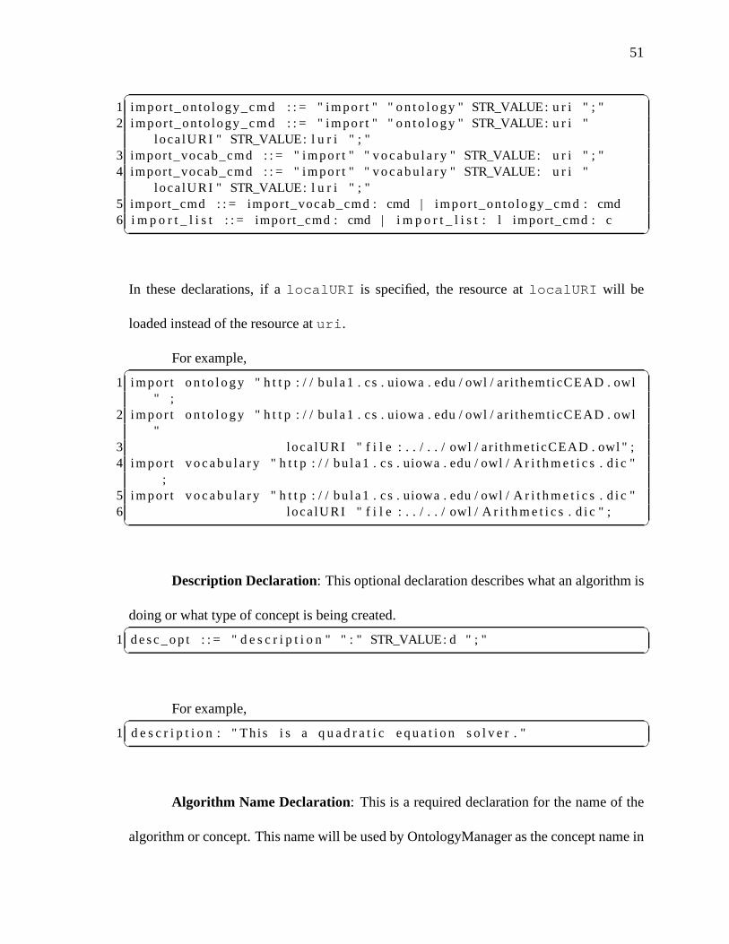
51
✞ ☎1 impor t_onto logy_cmd : : = " impor t " " on t o l ogy " STR_VALUE:u r i " ; "2 impor t_onto logy_cmd : : = " impor t " " on t o l ogy " STR_VALUE:u r i "
loca lURI " STR_VALUE: l u r i " ; "3 import_vocab_cmd : : = " impor t " " voc a bu l a r y " STR_VALUE: ur i " ; "4 import_vocab_cmd : : = " impor t " " voc a bu l a r y " STR_VALUE: ur i "
loca lURI " STR_VALUE: l u r i " ; "5 import_cmd : : = import_vocab_cmd : cmd | impor t_onto logy_cmd : cmd6 i m p o r t _ l i s t : : = import_cmd : cmd | i m p o r t _ l i s t : l import_cmd : c✝ ✆
In these declarations, if alocalURI is specified, the resource atlocalURI will be
loaded instead of the resource aturi.
For example,✞ ☎1 impor t on t o l ogy " h t t p : / / bu la1 . cs . uiowa . edu / owl / ar i themt icCEAD . owl
" ;2 impor t on t o l ogy " h t t p : / / bu la1 . cs . uiowa . edu / owl / ar i themt icCEAD . owl
"3 loca lURI " f i l e : . . / . . / owl / ar i thmet icCEAD . owl " ;4 impor t voc a bu l a r y " h t t p : / / bu la1 . cs . uiowa . edu / owl / A r it h m e t i c s . d i c "
;5 impor t voc a bu l a r y " h t t p : / / bu la1 . cs . uiowa . edu / owl / A r it h m e t i c s . d i c "6 loca lURI " f i l e : . . / . . / owl / A r i t h m e t i c s . d i c " ;✝ ✆
Description Declaration: This optional declaration describes what an algorithm is
doing or what type of concept is being created.✞ ☎1 de s c _op t : : = " d e s c r i p t i o n " " : " STR_VALUE: d " ; "✝ ✆
For example,✞ ☎1 d e s c r i p t i o n : " Th is i s a q u a d r a t i c e q u a t i o n s o l v e r . "✝ ✆
Algorithm Name Declaration: This is a required declaration for the name of the
algorithm or concept. This name will be used by OntologyManager as the concept name in

52
case this algorithm is added to the ontology. This declaration is always at the beginning of
the algorithm. For example,✞ ☎1 concep t : " gcd " ;✝ ✆
4.2.4 Terms (expressions)
Operands: Operands denote the elementary values in an expression. Anoperand
may be a literal, variable, or a phrase.✞ ☎1 l i t e r a l : : = STR_VALUE: v | INT_VALUE: v | FLOAT_VALUE: v2 term : : = l i t e r a l : v | IDENTIFIER : i d | ph r a s e : p✝ ✆
Selectors: For a primary expressionx, the selector expression✞ ☎1 x . f✝ ✆
denotes the fieldf of the valuex. For example, given the declarations:✞ ☎1 l o c a l : concep t ComplexPairi s2 record3 f i r s t : Complex ;4 second : Complex ;5 e nd r e c o r d ;6 endconcept ,7 x : ComplexPair ;✝ ✆
the user may write:✞ ☎1 x . f i r s t2 x . second✝ ✆

53
Grammar rule:✞ ☎1 term : : = term : t " . " IDENTIFIER : i d✝ ✆
Indexes: A primary expression of the form✞ ☎1 a [ i ]✝ ✆
denotes the elementi-th of the array. The valuei is called the index.
Grammar definitions for indexes:✞ ☎1 term : : = term : t " [ " term : i " ] "✝ ✆
Phrases: Given an termf of action conceptF ,✞ ☎1 f ( a1 , a2 , . . . an )✝ ✆
callsf with argumentsa1, a2, . . . an.
As defined in✞ ☎1 t e r m _ l i s t : : = term : p | t e r m _ l i s t : l COMMA term : p2 ph r a s e : : = IDENTIFIER : i d " ( " t e r m _ l i s t : v l " ) "3 ph r a s e : : = IDENTIFIER : i d " ( " " ) "✝ ✆
Operators: Operators combine operands into expressions.✞ ☎1 term : : = term : l b in_op term : r | "−" term : l | " no t " term : l2 b in_op : : = "+" | "−" | " * " | " / " | "%"3 | "==" | " != " | "<" | ">"4 | "<=" | ">="5 | " and " | " or "✝ ✆

54
For examples,✞ ☎1 x + 12 −33 a > b4 c < d5 ( x > y ) and ( t <= v )✝ ✆
Note that unlike programming languages, the semantics of each operator is not
defined in DAL but in the ontology via the CEAD process.
4.2.5 Commands (statements)
Assignments:✞ ☎1 ass ign_cmd : : = term : l h s "=" term : t " ; "✝ ✆
After an assignment statement, the evaluated value of the term t on the left hand side (LHS)
will be stored in the location of thelhs term.
If Command: The grammatical rules for If command is defined as:✞ ☎1 i f_cmd : : = " i f " term : p " then " c m d _ l i s t : c l " e n d i f " " ; "2 i f_cmd : : = " i f " term : p " then " c m d _ l i s t : c l " e l s e " c m d _ l i s t: c l 2 "
e n d i f " " ; "✝ ✆Or we can defined it as:✞ ☎
1 i f expr then2 s t a t e m e n t 1 ( s ) ;3 e l s e4 s t a t e m e n t 2 ( s ) ;5 e n d i f ;✝ ✆
Whereexpr is a boolean expression. Ifexpr is evaluated to true, thenstatement1(s)
are executed. Otherwise,statement2(s) are executed. Theelsebranch is optional.

55
For example,✞ ☎1 i f n < 3 then2 z = a ;3 e n d i f ;✝ ✆
While Command:✞ ☎1 whi le_cmd : : = " wh i le " term : p " do " c m d _ l i s t : c l " endwhi le "" ; "✝ ✆
In thewhile-loop construct of✞ ☎1 whi le expr do2 s t a t e m e n t ( s ) ;3 endwhi le ;✝ ✆
if the boolean expressionexpr is evaluated totrue, thestatement(s) is executed
and the expression is re-evaluated. This cycle repeats until expr becomesfalse.
For example, the Euclidean algorithm for finding gcd of two integers a, b is ex-
pressed by thewhile-loop as follows:✞ ☎1 whi le b != 0 do2 t = b ;3 b = a % b ;4 a = t ;5 endwhi le ;✝ ✆
For-loop Command:✞ ☎1 for loop_cmd : : = " f o r " ass ign_cmd : i c " i f " term : l c " beg in "c m d _ l i s t
: c l " end " " w i thNext " ass ign_cmd : ac✝ ✆

56
Thefor-loop formal syntax can be written as:✞ ☎1 f o r expr1 ; i f expr22 begin3 s t a t e m e n t ( s ) ;4 end5 wi thNext expr3 ;✝ ✆
which is equivalent to✞ ☎1 expr1 ;2 whi le expr2 do3 s t a t e m e n t ( s ) ;4 expr3 ;5 endwhi le ;✝ ✆
For example, the addition of two vectors can be written as✞ ☎1 f o r i = 1 ; i f i <= 32 begin3 v [ i ] = v1 [ i ] + v2 [ i ] ;4 end5 wi thNext i = i + 1 ;✝ ✆
4.3 DAL Use
The DAL use is illustrated by two examples. The first example is the DAL expres-
sion of the Euclidean algorithm for finding the greatest common divisor of two integers,
shown in Listing 4.2. The second example is the DAL expression of the Householder
algorithm for finding the solution of a system of linear equations, which is shown in Ap-
pendix C. For more detail on how to use this language with the actual DALSystem please
refer to Appendix A.

57
✞ ☎1 concep t : " gcd " ;2 d e s c r i p t i o n : " Th is i s f u n c t i o n f o r f i n d g r e a t e s t common d iv i s o r (
gcd ) o f two i n t e g e r s us i ng E uc l i de a n a l g o r i t h m . " ;3 i n p u t : a : i n t e g e r , b : i n t e g e r ;4 o u t p u t : c : i n t e g e r ;5 l o c a l : t : i n t e g e r ;67 whi le b != 0 do8 t = b ;9 b = a % b ;
10 a = t ;11 endwhi le ;12 c = a ;✝ ✆
Listing 4.2: Euclidean algorithm for finding GCD of two integers

58
CHAPTER 5DOMAIN DEDICATED VIRTUAL MACHINE AND SADL LANGUAGE
After domain concepts were associated with their computational meaning and the
computational language for the domain was developed, the automation of user algorithm
execution is based on two main software components: (1) A translator that maps user al-
gorithmA into an intermediate language expressionIL(A), called SADL, whose instruc-
tions are domain concepts associated with the URL of computational artifacts implement-
ing them, and (2) An interpreter operating on the intermediate language expressionIL(A)
generated by the translator, executing computational artifacts (web services) encountered at
each instruction. The translator can be implemented by conventional compiler construction
tools as discussed in Chapter 6. The interpreter can be implemented as a virtual machine,
which I will discuss in this chapter in section 5.1. The intermediate language of this virtual
machine will be discussed in sections 5.2 and 5.3.
5.1 Domain Dedicated Virtual Machine
The term Domain Dedicated Virtual Machine (DDVM) was coinedby Rus (2008)
to describe a virtual machine which performs domain user algorithms based on domain
concepts implemented by web services. This virtual machineautomates the execution of
DAL algorithms, which can instead be performed manually by aproblem solver using
computers as brain assistants, in order to increase the efficiency.
Formally, DDVM can be seen as a tuple DDVM =〈ConceptC,Execute,Next〉
where:

59
• ConceptC is a Concept Counter, that, for a given DAL algorithmA, points to the
URI of the concept in the OWL(DAL) to be performed next duringthe algorithm
execution;
• Execute() is the process that executes the computation meaning of the domain con-
cept assigned to ConceptC;
• Next() is a function which determines the next concept of the DAL algorithmA to
be performed by Execute() during algorithm execution.
The DDVM performs similarly with the Program Execution Loop(PEL) ((Rus 1993), p.
129) and therefore the algorithm execution by DDVM can be described by the following
Domain Algorithm Execution Loop(DAEL) (Rus 2013):✞ ☎1 ConceptC = getF i rs tDALConcept (DAL a l g o r i t h m )2 whi le ( ConceptC i s not End)3 Execute ( ConceptC ) ;4 ConceptC = Next ( ConceptC , DALalgori thm )5 E x t r a c t t he r e s u l t and d i s p l a y t he f i n a l o u t p u t t o t he us e r✝ ✆
At the high level view, DDVM is very similar to a Virtual Monitor (Popek & Goldberg
1974). The ConceptC is the counter part of the program counter, and the domain action
concept that the ConceptC refers to is similar to the function executed by the OS simu-
lating instructions of the machine implemented by the VM. Finally, Next() is similar to
the process that determines the next instruction of the program run by the VM. However,
the difference between a DDVM and a Virtual Monitor is that the memory of the machine
implemented by DDVM is all the ontologies imported by the DALalgorithm OWL(DAL),
and the processor of the DDVM is the collection of all processors available on the Web of

60
services participating in the OWL(DAL). Therefore, the DDVM is a true domain dedicated
virtual machine.
There are a few key things to note. Firstly, all the conceptual instructions of DDVM
are abstract, performing the user’s solution logically. Itis the DDVM that interprets these
conceptual instructions and executes the computational artifacts associated with these con-
ceptual instructions at the runtime. This means that the user solution in the form of DDVM
conceptual instructions remains useful for a longer periodof time; even when the underly-
ing computational artifacts change over time. Thus, this architecture encourages the reuse
of user solutions.
Secondly, due to the fact that DDVM makes remote procedure calls to web services
implementing action concepts, it essentially executes a distributed algorithm. Since our
implementation of DDVM is inspired by the stack based virtual machine, Java Virtual
Machine (JVM), we can think of DDVM as a JVM that conceptuallyruns on top of the
network across organization boundaries.
Finally, even though DDVM operates at the same abstraction level as other work-
flow engines in (Qin & Fahringer 2008, Gubala et al. 2006, Altintas et al. 2004), there are
some differences between our work and theirs. These differences result from the fact that
DDVM is designed to allow the domain user to manipulate data at much more fine grain
level such as allowing access to fields of composed data concepts or to array elements, and
declaring variables. Since DDVM is designed to facilitate more lively interactions between
domain users and their concepts, we pay more attention to theinput/output process of data
concepts to human readable form. On the other hand, current existing workflow engines

61
are designed to facilitate a Grid based environment where there is less interaction between
user and the computation process with mainly scheduled jobs. These differences lead us to
more of a full-pledged virtual machine while existing workflow engines tend to be more of
a simple composing engine.
5.2 Structure of SADL File
The Software Architecture Description Language (SADL) (Rus 2013) was devel-
oped by us to represent problem domain solutions in the abstract form. Its goal is similar
to the goal of the Intermediate Language (IL) used by Microsoft’s ASP.NET Framework
for providing a common ground for several higher level programming languages. SADL
serves as an Intermediate Language for all the DAL languagesdesigned to run on DDVMs.
SADL language design was inspired mainly by JVM intermediate language while
its syntax is based on XML representation. We choose XML for SADL representation
because the XML tag set provides a rich and powerful languagewhich is easily expandable
by adding new attributes to XML elements without breaking file format. Moreover, there
are many existing tools to process XML files.
A SADL file is organized into two sections:declarationand instructions. The
declaration section contains information about imported ontologies, input variables,
and output variables. Hence, it is divided into three subsections: imports, inputs, outputs.
Inside theimportssubsections areimportOntologytags which specify ontologies that this
algorithm may use. Theinputsandoutputsubsections containsinput andoutput tags re-
spectively for the declarations of input and output variables. The general structure of the

62
declarationsection is shown in Listing 5.1. We will discuss these tags indetail in Sec-
✞ ☎1 < d e c l a r a t i o n >2 < i m po r t s >3 < impor tOn to logy u r i ="URI ( Ontology1 ) " / >4 . . .5 < impor tOn to logy u r i ="URI ( OntologyN ) " / >6 < / i m po r t s >7 < i n p u t s >8 < i n p u t t ype ="URI ( t ype1 ) " index =" i 1 " / >9 . . .
10 < i n p u t t ype ="URI ( typeN ) " index =" iN " / >11 < / i n p u t s >12 < o u t p u t s >13 < o u t p u t t ype ="URI ( outputType ) " index =" o " / >14 < / o u t p u t s >15 < / d e c l a r a t i o n >✝ ✆
Listing 5.1: Declaration section of SADL file
tion 5.3.
After the declaration section is the section for DDVM conceptual instructions.
At this lowest level of SADL is a dynamic collection of primitive terms (instructions)
used to denote problem domain concepts such asComplex, addComplex, etc, or
IT specific terms such aspush, store, etc. All the instructions are sequential by
default. The branching and repetition constructs are implemented by usingjumping
instructions and labels to jump from one place to other in this sequence of instruc-
tions. Listing 5.2 shows an example of a SADL file for computing the sum of two real
numbers.

63
✞ ☎1 <?xml ve rs ion =" 1 . 0 " encod ing ="UTF−8" ?>2 < s a d l xm lns :xs =" h t t p : / /www. w3 . org / 2 0 0 1 / XMLSchema">3 < d e c l a r a t i o n >4 < i m po r t s >5 < impor tOn to logy u r i =" h t t p : / / bu la1 . cs . uiowa . edu / owl /cead . owl
" l o c a l =" f i l e : . . / OntologyManager / s r c / main / webapp /o n t o l o g i e s / cead . owl " / >
6 < impor tOn to logy u r i =" h t t p : / / bu la1 . cs . uiowa . edu / owl /ar i themt icCEAD . owl " l o c a l =" f i l e : . . / . . / owl / ar i thmet icCEAD. owl " / >
7 < / i m po r t s >8 < i n p u t s >9 < i n p u t t ype =" h t t p : / / bu la1 . cs . uiowa . edu / owl / a r i t h m e ti c . owl#
Real " i ndex =" 1 " / >10 < i n p u t t ype =" h t t p : / / bu la1 . cs . uiowa . edu / owl / a r i t h m et i c . owl#
Real " i ndex =" 2 " / >11 < / i n p u t s >12 < o u t p u t s >13 < o u t p u t t ype =" h t t p : / / bu la1 . cs . uiowa . edu / owl / a r i t h me t i c . owl#
Real " i ndex =" 3 " / >14 < / o u t p u t s >15 < / d e c l a r a t i o n >16 < i n i t t ype =" h t t p : / / bu la1 . cs . uiowa . edu / owl / a r i t h m e ti c . owl# Real "
i ndex =" 3 " / >17 < load index =" 1 " / >18 < load index =" 2 " / >19 <addR xmlns =" h t t p : / / bu la1 . cs . uiowa . edu / owl / a r i t h m et i c . owl# "
params =" 2 " / >20 < s t o r e index =" 3 " / >21 < / s a d l >✝ ✆
Listing 5.2: Two push instructions for complex data types then adding them together usingaddComplex concept

64
5.3 DDVM Conceptual Instructions
In this section, I will provide detailed explanations aboutthe semantics of each
instruction of our virtual machine, DDVM. For each instruction, I show its syntax as XML
element and the corresponding attributes. Then I explain how the virtual machine should
behave for that instruction.
Before discussing the DDVM instructions set, I would like todiscuss the internal
architecture of our virtual machine. The first component of our virtual machine is the
concept counter. At any time, this counter points to the current concept to be executed.
After the execution of that concept finishes, the counter moves to the next concept. Since
our virtual machine is a stack based one, the second most important component is the stack.
This stack is initially empty, and during the virtual machine execution, it holds intermediate
results of the computation process. Finally, we use virtualregisters to hold the contents of
the variables used in user algorithm, including input, output and local variables. The virtual
registers are stored in a dynamic array. To access the content of a register, we need to
provide the index of that register in the instruction such asload andstore. When the virtual
machine is initialized, it loads all the contents of input parameters into input registers, the
output register and local registers are initialized to the default values of their types. Finally,
the virtual machine maintains an ontology model which loadsall the imported ontologies
and provides the reasoning service for the virtual machine during the execution. Provided
these assumptions about the virtual machine architecture,we can move on to examine the
instruction set of this virtual machine.

65
5.3.1 Declaration Intructions
The first type of declaration instructions is the importOntology instruction. DDVM
will load the ontology O aturi attribute of the XML tag the URI(O). If thelocal attribute
is present, then the content of the URI(O) will be loaded locally with the content of the file
at URI(localFile.owl).✞ ☎1 < impor tOn to logy u r i ="URI (O) " l o c a l ="URI ( l o c a l F i l e . owl ) " / >✝ ✆
After loading this instruction, all the classes, individuals and their properties of this ontol-
ogy are loaded into the DDVM ontology model for later queries. A concrete example of
importing the arithmeticCEAD.owl ontology at the URI of
http://bula1.cs.uiowa.edu/owl/arithemticCEAD.owl is shown below.✞ ☎1 < impor tOn to logy u r i =" h t t p : / / bu la1 . cs . uiowa . edu / owl /
ar i themt icCEAD . owl "2 l o c a l =" f i l e : . . / . . / owl / ar i thmet icCEAD . owl " / >✝ ✆
The second type of declaration instructions is the input variable declaration instruc-
tion.✞ ☎1 < i n p u t t ype ="URI ( varType ) " index =" r " / >✝ ✆
This instruction has two attributes,type andindex. Thetype attribute is the URI of
the type of the variable. Theindex attribute is the index of the DDVM register allocated
to this variable. For example, the instruction✞ ☎1 < i n p u t t ype =" h t t p : / / bu la1 . cs . uiowa . edu / owl / a r i t h m e ti c . owl# Real "2 index =" 2 " / >✝ ✆

66
means that the DDVM register 2 is allocated for an input variable of type
http://bula1.cs.uiowa.edu/owl/arithmetic.owl#Real.
Similarly, the output instruction describes thetype and the DDVM register index
of the output variable.✞ ☎1 < o u t p u t t ype ="URI ( varType ) " index =" r " / >✝ ✆
Both attributes have the same meaning as those of theinput instruction.
5.3.2 Virtual Register Traffic
DDVM registers typically hold variable values. Register index starting from 1 are
set aside for the algorithm’s input variables. The next registers are for output variables.
Local variables are assigned to registers after the output registers. DDVM registers are
untyped, so they can hold any kind of value.
Theload instruction pushes the content of a DDVM register on top of the stack
(TOS). The register value is unaffected by the instruction.✞ ☎1 < load index =" r " / >✝ ✆
Theindex attribute specifies the index of the DDVM register needed to be loaded. Note
that the value of each register is a data item, so it contains both value and the type of the
value.
The store instruction pops a value from the DDVM stack and stores it in the
content of the specified DDVM register.✞ ☎1 < s t o r e index =" r " / >✝ ✆

67
Theindex attribute specifies the index of the DDVM register receivingthe value. The
whole data item content including both value and the type of the value are stored in the
register.
ThepushStr instruction pushes a string value of typecead:String on TOS.✞ ☎1 < pus hS t r va l ue =" s t r i n g " / >✝ ✆
Thevalue attribute holds the value of the string.
TheloadConst instruction converts the constant value on TOS to the type speci-
fied by the instruction.✞ ☎1 < loadCons t conceptURI="URI ( c ) " / >✝ ✆
TheconceptURI attribute specifies the URI of the concept to be loaded. The DDVM
makes a call to the input filter of conceptc to convert the value on TOS to the type of
conceptc. The received value will be pushed back to TOS.
Theinit instruction initializes the default value for a variable.✞ ☎1 < i n i t t ype ="URI ( c ) " i ndex =" r " / >✝ ✆
Thetype attribute specifies the type of this default value. Theindex attribute specifies
the register which holds the value of the initialized variable.
5.3.3 Action Instructions
This is a special class of instructions of each DDVM. It contains all the action
concepts of the application domain. The template of these instructions is shown below.

68
✞ ☎1 <conceptURI params =" p " / >✝ ✆
Theparams attribute specifies the number of input parameters that the DDVM needs to
pass to the concept. The result of this call to the action concept will be pushed back to TOS.
For example, the call to the conceptmultiplyR of the arithmetic domain looks like:✞ ☎1 < mul t i p l yR xmlns =" h t t p : / / bu la1 . cs . uiowa . edu / owl / a r it h m e t i c . owl
# "2 params =" 2 " / >✝ ✆
That means the DDVM will pop 2 items from the stack and send them to the IT arti-
fact implementing the concept multiplyR for execution. Theresult is a value of type
http://bula1.cs.uiowa.edu/owl/arithmetic.owl#Realand will be pushed
on TOS.
The execution of this instruction using a web services as theimplementation artifact
is shown in the following algorithm:
1. The DDVM makes a SOAP call to the remote web service implementing the seman-
tics of the corresponding domain concept.
2. The current execution threadT1 of the DDVM at machineA is blocked and waits for
the result from the remote server at a machineB.
3. The remote server at machineB creates a processT2 executing the corresponding
web services.
4. After the processT2 finished, the remote server returns the result to the machineA.
5. The machineA notifies the threadT1 of the DDVM.

69
6. The threadT1 receives the result from machineB and pushes it to the TOS (Top of
the Stack).
After that the concept counter points to the next instruction.
5.3.4 Field Access Instructions
Thegetfield instruction pushes the value of a particular field of a data item on
TOS. The form of agetfield instruction follows:✞ ☎1 < g e t f i e l d f i e l d =" f ie ldName " / >✝ ✆
When encountering this instruction, the DDVM will pop the data item on TOS, then DDVM
accesses the field specified by thefield attribute. The result will be pushed back on TOS.
For example, if TOS holds a value of a complex number with two fieldsRealPart and
ImgPart.✞ ☎1 < g e t f i e l d f i e l d =" R e a l P a r t " / >✝ ✆
The instruction pops the complex number out of TOS. The DDVM reads the value of the
RealPart field and pushes the value back to TOS.
Theputfield instruction pushes a value to a particular field of a data itemon
TOS. The syntax of aputfield instruction follows:✞ ☎1 < p u t f i e l d t ype =URI ( c ) f i e l d =" f ie ldName " / >✝ ✆
This instruction pops two values from TOS. The first value (v) is the value that should be
stored at the field (fieldName) specified by the attributefield of theputfield instruc-
tion. The second value is a reference to the data item (x) with the field to be stored. When

70
the instruction completes, the value fieldfieldName of x will be v and the stack will
have two fewer items.
5.3.5 Branching
There are two kinds of instructions that accommodate conditional branches, i.e.
jumpfalse andjumptrue. Thejumpfalse instruction expects that the TOS is a
boolean value of typecead:Boolean.✞ ☎1 < j um p f a l s e l a b e l =" labelName " / >✝ ✆
The branch is taken if the boolean value is true. Otherwise, the DDVM concept counter
will jump to the position with the labellabelName.
Thejumptrue instruction is similar to thejumpfalse instruction with the op-
posite action. That means, the branch is taken if the booleanvalue is false. Otherwise, the
DDVM concept counter will jump to the specified label position.✞ ☎1 < jumpt rue l a b e l =" labelName " / >✝ ✆

71
CHAPTER 6TRANSLATION FROM DAL TO SADL
The mapping of the DAL algorithms into SADL expressions can be done by the
domain expert by hand. This is feasible for toy problems. Formore sophisticated prob-
lems it is beneficial to automate this process. I have developed a translator that maps DAL
algorithms into SADL instructions which are then interpreted by a DDVM. This trans-
lator can be implemented using conventional compiler construction tools (Aho, Sethi &
Ullman 1986, Fischer, Cytron & LeBlanc 2010) with some modification to take advantage
of domain knowledge in the ontology for concept disambiguation and to tailor to DDVM
instructions as the target code.
Our translator follows the traditional processing pipeline in compiler design as
shown in Figure 6.1. In this pipeline, the Lexical Analyzer is specified by a set of reg-
ular expressions, generating a token stream from the DAL expression. The token stream is
then passed to the Parser whose grammar is specified by an LR(1) grammar (Knuth 1965)
in the form of BNF rules. The Parser generates an Abstract Syntax Tree (AST) from the
token stream. The AST is then annotated by the Semantic Analyzer with deeper semantic
information on each node such as type information. Finally,the Code Generator receives
the Annotated AST and generates the corresponding SADL code.
Among the components of the processing pipeline, we use standard tools for con-
structing Lexical Analyzer (JFlex)1 and Parser (JavaCup2). The most interesting com-
1Available at http://jflex.de/
2Available at http://www2.cs.tum.edu/projects/cup/

72
DAL expressionLexical
AnalyzerParser
Semantic
Analyzer
Code
GeneratorSADL expression
Token stream
AST
Annotated AST
Semantic
Figure 6.1: DAL Translator processing pipeline
ponents are the Semantic Analyzer and the Code Generator. Both of these components
employ domain knowledge to help disambiguate concepts. Forexample, the Semantic
Analyzer uses the transitivecead:castable ontological relation to resolve ambigui-
ties when processing overloaded concepts, e.g. operators,action concepts as presented in
sections 6.1.3 and 6.1.5.
The DALTranslator is designed using Visitor design pattern(Gamma, Helm, John-
son & Vlissides 1995) so that for each type of AST node, the DALTranslator has a cor-
responding method to process the code generation for that AST node. DALTranslator is
organized as three visitors:
TopDeclVisitor : is our Semantic Analyzer. It is the top-level visitor for processing AST’s
declaration nodes, such as Variable Declaration Nodes. During this process, it is

73
assigned correct types (linked to conceptURI) for all declared variables including
input, output and local variables. The information for thislinking process is pro-
vided mostly by the user dictionary. This type information will be used later by Con-
ceptGeneratorVisitor to generate DDVM instructions, especially for selecting correct
overloaded operators like+,−, ∗, /, etc.
ConceptGeneratorVisitor : implements our Code Generator. It is the main visitor which
is responsible for generating DDVM instructions from AST. There are some cases
involving some LHS nodes of an assignment that need to be handled by another
visitor LHSVisitor.
LHSVisitor is responsible for generating code for LHS of an assignment.LHSVisitor uses
ConceptGeneratorVisitor as its ValueVisitor as specified in some of its methods.
6.1 ConceptGeneratorVisitor
The ConceptGeneratorVisitor starts with the first command node in the body of a
DAL algorithm (ignoring top declaration nodes, which are processed by the TopDeclVis-
itor). In this section, I discuss the process of handling each node in some detail with the
following pattern:
1. Present the BNF rules that creates the AST node.
2. List the properties of that AST node, such as list of its children, LHS term and LHS
term.
3. Show the algorithm to generate the DDVM instructions for that particular node.

74
6.1.1 Literals
The LiteralNode is generated by the following BNF rules:✞ ☎1 l i t e r a l : : = STR_VALUE:v | INT_VALUE:v | FLOAT_VALUE:v✝ ✆
From this rule the LiteralNode is created with propertiesvalue=v, and the type is deter-
mined by the type of the literal. The algorithm for generating DDVM instructions is shown
in Algorithm 6.1. TheEMITCONSTANTLOAD(v, t) procedure generates the following
Algorithm 6.1 Generating literal load algorithm
1: procedure VISIT(n: LiteralNode) ⊲ Visiting a literal node
2: EMITCONSTANTLOAD(n.value, n.type)
3: end procedure
DDVM instructions.✞ ☎1 < pus hS t r va l ue =" v " / >2 < loadCons t conceptURI="URI ( t ) " / >✝ ✆
Note that the result of this loadConst will be stored on TOS.
6.1.2 Local Reference
The LocalReferenceNode is created by the following BNF rules:✞ ☎1 term : : = IDENTIFIER:id✝ ✆

75
From this rule, the LocalReferenceNode gets its propertyvariable=id. The algorithm
for generating DDVM instructions is shown in Algorithm 6.2 TheEMITLOAD(r) proce-
Algorithm 6.2 Generating local reference algorithm
1: procedure VISIT(n: LocalReferenceNode) ⊲ Visiting a local reference node
2: varAttr ← currentSymbolTable.RETRIEVESYMBOL(n.variable)
3: n.SETRESULTLOCAL(varAttr.localIndex)
4: EMITLOAD(n.localIndex)
5: end procedure
dure generates the DDVM instructions for loading the corresponding register which holds
the variable to TOS.✞ ☎1 < load index =" r " / >✝ ✆
6.1.3 Computing Expressions
Computing expressions are generated by the following BNF rules:✞ ☎1 term : : = t e r m : l b in_op t e r m : r | "−" t e r m : l | " no t " t e r m : l2 b in_op : : = "+" | "−" | " * " | " / " | "%"3 | "==" | " != " | "<" | ">"4 | "<=" | ">="5 | " and " | " or "✝ ✆
The algorithm for generating DDVM instructions is shown in Algorithm 6.3. The EMIT-
OPERATION(n) procedure generates the DDVM instructions for the arithmetic operations.

76
Algorithm 6.3 Generating computing expression algorithm
1: procedure VISIT(n: Computing) ⊲ Visiting a computing node such as AddNode,
SubtractNode, etc.
2: VISITCHILDREN(n)
3: loc← ALLOCLOCAL( )
4: n.SETRESULTLOCAL(loc)
5: EMITOPERATION(n)
6: end procedure
The procedure finds the correct concept linked with the operation with a matching signa-
ture in the ontology. For example, the operation+ could be the addition for integers
http://bula1.cs.uiowa.edu/owl/arithmetic.owl#addI
or the addition of real numbers
http://bula1.cs.uiowa.edu/owl/arithmetic.owl#addR
The instruction generator will find the first concept whose signature matches the input pa-
rameters type. An input parameter type is considered as matching the concept signature’s
parameter type if the input parameter type is castable to theconcept signature’s parameter
type.
For example, in the expression1 + 3.1, DDVM will generate+ asaddR. Because
3.1 is of type#Real, the concept#addI doesn’t match. However, there exists a filter
#intToDouble which converts an#Integer number to a #Real number. Thus, type
#Integer is castable to type#Real. Therefore, the concept#addR matches. So, we get✞ ☎

77
1 <addR xmlns =" h t t p : / / bu la1 . cs . uiowa . edu / owl / a r i t h m e ti c . owl# "params =" 2 " / >✝ ✆
6.1.4 Assignment
The assignment node is generated by the following BNF rule:✞ ☎1 ass ign_cmd : : = t e r m : l h s "=" t e r m : t " ; "✝ ✆
So, itslhs andrhs properties are pointing to its childrenlhs and t respectively. The
algorithm for generating DDVM instructions is shown in Algorithm 6.4.
Algorithm 6.4 Generating assignment algorithm
1: procedure VISIT(n: AssignNode) ⊲ Visiting an assignment node.
2: lhsV isitor ← new LHSVISITOR(this)
3: lhsV isitor.VISIT(n.lhs)
4: VISIT(n.rhs)
5: lhsV isitor.EMITSTORE(n.rhs.GETRESULTLOCAL())
6: end procedure
ThelhsV isitor.EMITSTORE procedure will be discussed in Section 6.2.

78
6.1.5 Phrase Node
PhraseNodes are generated by the following grammar rules:✞ ☎1 t e r m _ l i s t : : = t e r m : p | t e r m _ l i s t : l COMMA t e r m : p2 ph r a s e : : = IDENTIFIER:id " ( " t e r m _ l i s t : v l " ) "3 ph r a s e : : = IDENTIFIER:id " ( " " ) "✝ ✆
The algorithm for its code generation is shown in Algorithm 6.5. The FINDMATCHEDSIG-
Algorithm 6.5 Generating phrases algorithm
1: procedure VISIT(n: PhraseNode) ⊲ Visiting a phrase node.
2: conceptURI ←FINDMATCHEDSIGNATURE(n.concept)
3: VISITCHILDREN(n)
4: EMITACTIONCONCEPT(conceptURI)
5: end procedure
NATURE procedure is the same as that of Algorithm 6.3. TheEMITACTIONCONCEPT
procedure emits DDVM instructions for domain action concept. For example, with the ex-
pressionsqrt(4.0), the concept generator will first look up a matched concept from user
dictionary. Assume that it findshttp://bula1.cs.uiowa.edu/owl/arithmetic.
owl\#sqrtR. The concept generator then finds the number of input parameters that the
conceptsqrt has and gets1. So, the generator emits the following DDVM instruction:✞ ☎1 < s q r t R xmlns =" h t t p : / / bu la1 . cs . uiowa . edu / owl / a r i t h m et i c . owl# "
params =" 1 " / >✝ ✆
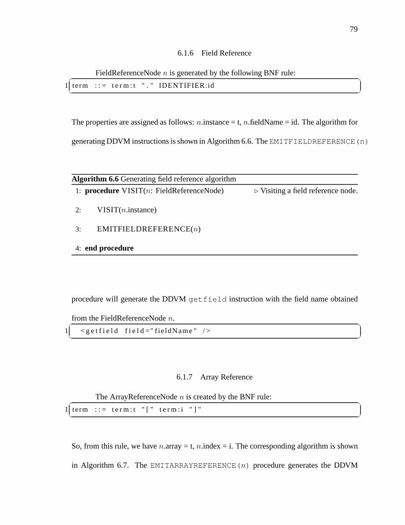
79
6.1.6 Field Reference
FieldReferenceNoden is generated by the following BNF rule:✞ ☎1 term : : = t e r m : t " . " IDENTIFIER:id✝ ✆
The properties are assigned as follows:n.instance = t,n.fieldName = id. The algorithm for
generating DDVM instructions is shown in Algorithm 6.6. TheEMITFIELDREFERENCE(n)
Algorithm 6.6 Generating field reference algorithm
1: procedure VISIT(n: FieldReferenceNode) ⊲ Visiting a field reference node.
2: VISIT(n.instance)
3: EMITFIELDREFERENCE(n)
4: end procedure
procedure will generate the DDVMgetfield instruction with the field name obtained
from the FieldReferenceNoden.✞ ☎1 < g e t f i e l d f i e l d =" f ie ldName " / >✝ ✆
6.1.7 Array Reference
The ArrayReferenceNoden is created by the BNF rule:✞ ☎1 term : : = t e r m : t " [ " t e r m : i " ] "✝ ✆
So, from this rule, we haven.array = t,n.index = i. The corresponding algorithm is shown
in Algorithm 6.7. TheEMITARRAYREFERENCE(n) procedure generates the DDVM

80
Algorithm 6.7 Generating array reference algorithm
1: procedure VISIT(n: ArrayReferenceNode) ⊲ Visiting a array reference node.
2: VISIT(n.GETARRAY())
3: VISIT(n.GETINDEX())
4: EMITARRAYREFERENCE(n)
5: end procedure
aload instruction. Thetype attribute required by theaload instruction is the base type
of this array. This base type is retrieved from the ontology via the propertycead:hasBaseType
of the classcead:ArrayDataConcept.✞ ☎1 < a l oa d type ="BASETYPE( n .GETARRAY( ) ) " / >✝ ✆
6.1.8 Conditional Branching
The IfNoden is generated by the following grammar rules:✞ ☎1 i f_cmd : : = " i f " t e r m : p " then " c m d _ l i s t : c l " e n d i f " " ; "2 i f_cmd : : = " i f " t e r m : p " then " c m d _ l i s t : c l " e l s e " c m d _ l i s t: c l 2 "
e n d i f " " ; "✝ ✆Properties forn are specified as follows:n.boolExpr = p,n.action = cl,n.alternativeAction
= cl2. Thus, the algorithm for generating DDVM instructionsis shown in Algorithm 6.8.
In this algorithm, the procedureGENLABEL generates a new label forfalseLabel and
endLabel. EMITJUMPFALSE will produce✞ ☎1 < j um p f a l s e l a b e l =" f a l s e L a b e l " / >✝ ✆
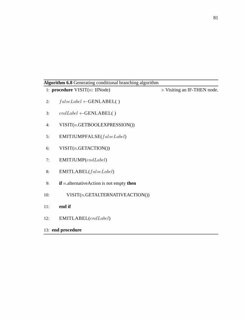
81
Algorithm 6.8 Generating conditional branching algorithm
1: procedure VISIT(n: IfNode) ⊲ Visiting an IF-THEN node.
2: falseLabel ←GENLABEL( )
3: endLabel ←GENLABEL( )
4: VISIT(n.GETBOOLEXPRESSION())
5: EMITJUMPFALSE(falseLabel)
6: VISIT(n.GETACTION())
7: EMITJUMP(endLabel)
8: EMITLABEL( falseLabel)
9: if n.alternativeAction is not emptythen
10: VISIT(n.GETALTERNATIVEACTION())
11: end if
12: EMITLABEL( endLabel)
13: end procedure

82
while EMITJUMP generates✞ ☎1 <jump l a b e l =" endLabe l " / >✝ ✆
So in total, this algorithm generates the following DDVM instructions template:✞ ☎1 < !−− check boo lExpr code−−>2 < j um p f a l s e l a b e l =" f a l s e L a b e l " / >3 < !−− a c t i o n code−−>4 <jump l a b e l =" endLabe l " / >5 < l a b e l name=" f a l s e L a b e l " / >6 < !−− a l t e r n a t i v e A c t i o n code−−>7 < l a b e l name=" endLabe l " / >✝ ✆
6.1.9 Loops
The WhileNoden is generated by the BNF rule:✞ ☎1 whi le_cmd : : = " wh i le " t e r m : p " do " c m d _ l i s t : c l " endwhi le "" ; "✝ ✆
Its properties are set up asn.boolExpr = p,n.action = cl. With these information, the code
generation algorithm is shown in Algorithm 6.9. Proceduresin this algorithm are very
similar to those of Algorithm 6.8. However, the code template is different, as seen below:✞ ☎1 < l a b e l name=" loopLabe l " / >2 < !−− check boo lExpr code−−>3 < j um p f a l s e l a b e l =" doneLabe l " / >4 < !−− a c t i o n code−−>5 <jump l a b e l =" loopLabe l " / >6 < l a b e l name=" doneLabe l " / >✝ ✆
An actual code sample for while-loop is shown in the SADL codefor the Euclidean algo-
rithm in Listing D.1.

83
Algorithm 6.9 Generating loops algorithm
1: procedure VISIT(n: WhileNode) ⊲ Visiting a WHILE node.
2: doneLabel ←GENLABEL( )
3: loopLabel ←GENLABEL( )
4: EMITLABEL( loopLabel)
5: VISIT(n.GETBOOLEXPRESSION())
6: EMITJUMPFALSE(doneLabel)
7: VISIT(n.GETACTION())
8: EMITJUMP(loopLabel)
9: EMITLABEL( doneLabel)
10: end procedure
6.2 LHSVisitor
6.2.1 Local References
TheLocalStore command, when executed by theEMITSTORE procedure from
Section 6.1.4, will emit the DDVMstore instruction. The information about the register
to be used is the localIndex of the variable.✞ ☎1 < s t o r e index =" l o c a l I n d e x " / >✝ ✆
6.2.2 Field Reference
TheFieldStore command, when executed by theEMITSTORE procedure from
Section 6.1.4, will emit the DDVMputfield instruction. The information about the

84
Algorithm 6.10 Generating LHS local reference algorithm
1: procedure VISIT(n: LocalReferenceNode) ⊲ Visiting a local reference node
2: varAttr ← currentSymbolTable.RETRIEVESYMBOL(n.variable)
3: n.SETTYPE(varAttr.variableType)
4: SETSTORE(new LocalStore(n.GETTYPE(),varAttr.localIndex)))
5: end procedure
Algorithm 6.11 Generating LHS field reference algorithm
1: procedure VISIT(n: FieldReferenceNode) ⊲ Visiting a field reference node
2: valueV isitor.VISIT(n.instance)
3: SETSTORE(new FieldStore(n.GETTYPE(),n.fieldName)))
4: end procedure
field type (ft) and the field name (fn) is provided by the FieldStore object.✞ ☎1 < p u t f i e l d t ype =" f t " f i e l d =" fn " / >✝ ✆
6.2.3 Array Reference
TheArrayStore command, when executed by theEMITSTORE procedure from
Section 6.1.4, will emit the DDVMastore instruction. The information about the field
type (ft) is provided by the FieldStore object.✞ ☎1 < a s t o r e type =" f t " / >✝ ✆

85
Algorithm 6.12 Generating LHS array reference algorithm
1: procedure VISIT(n: ArrayReferenceNode) ⊲ Visiting a array reference node
2: valueV isitor.VISIT(n.GETARRAY())
3: valueV isitor.VISIT(n.GETINDEX())
4: SETSTORE(new ArrayStore(n.GETARRAY().GETTYPE())))
5: end procedure

86
CHAPTER 7DOMAIN ONTOLOGY EVOLUTION
One of the key ideas in our approach is to provide a mechanism that allows domain
experts to create and extend their domain knowledge base. The process of expanding a
user’s knowledge base via DAL expressions is called Domain Ontology Evolution (DOE).
This process simulates and records the process of a domain expert learning about a domain
and keeps expanding her knowledge base during the problem solving process. For example,
during a problem solving process, a domain expert can discover a new action concept which
is represented as a DAL algorithm such as the steps leading tothe solution of a quadratic
equation (ax2+bx+c = 0). Or, she might discover a new data concept such as the complex
numbers when she tries to solve a quadratic equation which has no real number solutions
(the case when∆ = b2 − 4ac < 0). The approach of this thesis to addressing these two
cases is implemented by two proceduresadd2Onto andaddData2Onto presented in
the following sections.
7.1 Creating new Action Concepts - add2Onto
The general idea for adding a new action concept to the user ontology consists of
the following steps:
1. generate a web service instance for that action concept from the SADL code of that
concept,
2. create a new individual of classActionConcept in user own ontology (UOO),
3. automatically perform the process of associating the newconcept with the generated

87
service instance.
The most important design idea is step 1, i.e. to export the action concept as a web service
instead of exposing the SADL code or DAL solution directly. If the process of evolution
requires the SADL code or DAL solution to be exposed directly, it implies a cascading
exposure of all other SADL codes of concepts that the original new concept imported.
Moreover, the execution of these SADL codes will take place on the user machine, which
will involve the problem of having no access to certain resources that these SADL codes
require. On the other hand, if we export the action concept asa web service, the concept
will be exposed as a standalone and composable concept like every other primitive concept
in the domain ontology.
This idea is formally expressed in Algorithm 7.1. TheGENERATESADL procedure
Algorithm 7.1 Creating new action concept algorithm
1: procedure ADD2ONTO(DAL: DALExpression) ⊲ create new action concept.
2: GENERATESADL(DAL)
3: ast← PARSE(DAL)
4: GENERATEXSD(ast)
5: GENERATEWSDL(ast)
6: CREATENEWACTIONCONCEPT(ast)
7: end procedure
uses a DALTranslator discussed in chapter 6 to generate the SADL expression from the

88
DAL expression. This SADL expression is then stored in the user private space for later
use as the service instance of thisDAL action concept. Next we obtain an AST of the
DAL expression from thePARSE procedure.
TheGENERATEXSD procedure walks through theast tree to generate the corre-
sponding XSD schema file for theDAL service instance from the input and output decla-
rations of theDAL expression.
The GENERATEWSDL procedure also walks theast to generate the WSDL file
for theDAL service instance. The patterns for generating the WSDL file are shown in
Table 7.1.
Finally, theCREATEACTIONNEWCONCEPT procedure, shown in Algorithm 7.2,
creates a new action concept individualacInd in the user own ontology. In this procedure,
for each input node from theast, oneInput individual is created with corresponding order
and type, then assigned to the propertyhasInput of acInv. Similar steps are repeated
for output parameter.
The above scenario is demonstrated further with the examplein high school algebra
that maps the algorithm solving quadratic equations into a new concept calledSolver. We
assume that the DAL expression of the algorithm that solves quadratic equations is written
as follows and saved as the filesolver.dal shown in Listing 7.1.
Then using the DAL Console program, the user executes the command✞ ☎1 add2Onto s o l v e r . da l✝ ✆
The generated SADL file is shown in Listing 7.2.

89
WSDL file Properties Value Comment
schemaLocation the URI of XSD file generated byGENERATEXSDinput message (conceptName) XSD type is named as
conceptNameoutput message (conceptName)Response XSD type for output message
of conceptadd is like
addResponseportType (conceptName)PortType for exampleaddPortTypeoperation (conceptName) for exampleaddservice (conceptName) name of the web service
instance is after the concept
namelocation http://(server)/OntologyManager/services/(conceptName) URI of the web service
instance
Table 7.1: Patterns for generating WSDL files

90
Algorithm 7.2 Creating new action concept individual algorithm
1: procedure CREATEACTIONNEWCONCEPT(ast: ProgramNode) ⊲ create new
action concept.
2: m← LOADONTOLOGYMODEL(user-CEAD.owl)
3: acInd←m.CREATEINDIVIDUAL(ast.ConceptName, “ActionConcept”)
4: for i = 1 to ast.InputList.SIZEdo
5: inputNode← ast.InputList.GET(i)
6: inputInd←m.CREATEINDIVIDUAL(ast.ConceptName+i, “Input”)
7: inputInd.ADDPROPERTY(“inputType”,inputNode.GETTYPE())
8: inputInd.ADDPROPERTY(“order”,i)
9: acInd.ADDPROPERTY(“hasInput”,inInd)
10: end for
11: acInd.ADDPROPERTY(“hasOutput”,ast.GETOUTPUTTYPE())
12: serviceInd ← m.CREATEINDIVIDUAL(ast.ConceptName + “ServiceIn-
stance”, “ServiceInstance”)
13: SETUPWSDLPROPERTY(serviceInd) ⊲ Assign service information from
WSDL to this individual
14: agentInd ← m.CREATEINDIVIDUAL(ast.ConceptName + “Agent”,
“Agent”)
15: acInd.ADDPROPERTY(“hasAgent”,agentInd)
16: agentInd.ADDPROPERTY(“implementedBy”,serviceInd)
17: end procedure

91
OWL Properties Value Comment
InputschemaLocation the URI of XSD file generated byGENERATEXSDinput message (conceptName) XSD type is named as
conceptNameoutput message (conceptName)Response XSD type for output message
of conceptadd is like
addResponseportType (conceptName)PortType for exampleaddPortTypeoperation (conceptName) for exampleaddservice (conceptName) name of the web service
instance is after the concept
namelocation http://(server)/OntologyManager/services/(conceptName) URI of the web service
instance
Table 7.2: Patterns for generating OWL individual

92
✞ ☎1 c o n c e p t : " S o l ve r " ;2 d e s c r i p t i o n : " Th is i s an e q u a t i o n s o l v e r . " ;3 message i n p u t : " P rov ide t he c o e f f s o f your q u a d r a t i c e q u a ti o n ax
^2 + bx + c = 0 " ;4 i n p u t : a : r e a l , b : r e a l , c : r e a l ;5 o u t p u t : r e s u l t : R e a l P a i r ;6 l o c a l : t : r e a l , x1 : r e a l , x2 : r e a l ;7 t = b * b − 4 * a * c ;8 i f t > 0 then9 x1 = (−b − s q r t ( t ) ) / (2 * a ) ;
10 x2 = (−b + s q r t ( t ) ) / (2 * a ) ;11 r e s u l t . f i r s t = x1 ;12 r e s u l t . second = x2 ;13 e l s e14 p r i n t ( " t he e q u a t i o n has no r e a l s o l u t i o n " ) ;15 e n d i f ;✝ ✆
Listing 7.1: DAL algorithm for solving quadratic equations
The OWL entry for the generatedSolver concept is shown in Lising 7.3. From
now on, the user can use the concept "Solver" as any other primitive concepts by executing
the command✞ ☎1 > S o l ve r ( 1 , 4 , 3)2 ( f i r s t : −3.0 , second :−1.0 , )✝ ✆
or she can use this concept in another DAL expression for example✞ ☎1 x = S o l ve r ( a , b , c ) ;2 p r i n t ( " F i r s t s o l u t i o n of t he e q u a t i o n : " ) ;3 p r i n t ( x . f i r s t ) ;4 p r i n t ( " Second s o l u t i o n of t he e q u a t i o n : " ) ;5 p r i n t ( x . second ) ;✝ ✆
Notice that since all the code involved in thead2Onto procedure is automatically created
the student learning to solve quadratic equations using theDALSystem manipulates only
algebraic concepts.
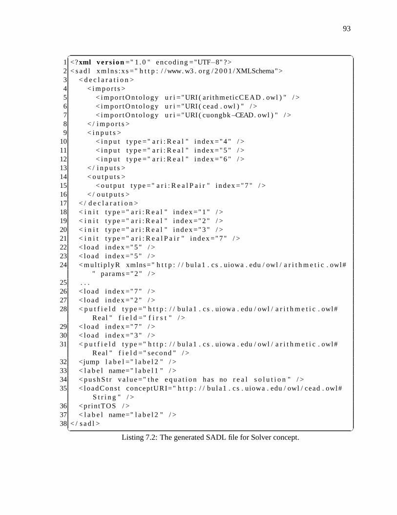
93
✞ ☎1 <?xml ve rs ion =" 1 . 0 " encod ing ="UTF−8" ?>2 < s a d l xm lns :xs =" h t t p : / /www. w3 . org / 2 0 0 1 / XMLSchema">3 < d e c l a r a t i o n >4 < i m po r t s >5 < impor tOn to logy u r i ="URI ( ar i thmet icCEAD . owl ) " / >6 < impor tOn to logy u r i ="URI ( cead . owl ) " / >7 < impor tOn to logy u r i ="URI ( cuongbk−CEAD. owl ) " / >8 < / i m po r t s >9 < i n p u t s >
10 < i n p u t t ype =" a r i : R e a l " i ndex =" 4 " / >11 < i n p u t t ype =" a r i : R e a l " i ndex =" 5 " / >12 < i n p u t t ype =" a r i : R e a l " i ndex =" 6 " / >13 < / i n p u t s >14 < o u t p u t s >15 < o u t p u t t ype =" a r i : R e a l P a i r " i ndex =" 7 " / >16 < / o u t p u t s >17 < / d e c l a r a t i o n >18 < i n i t t ype =" a r i : R e a l " i ndex =" 1 " / >19 < i n i t t ype =" a r i : R e a l " i ndex =" 2 " / >20 < i n i t t ype =" a r i : R e a l " i ndex =" 3 " / >21 < i n i t t ype =" a r i : R e a l P a i r " i ndex =" 7 " / >22 < load index =" 5 " / >23 < load index =" 5 " / >24 < mul t i p l yR xmlns=" h t t p : / / bu la1 . cs . uiowa . edu / owl / a ri t h m e t i c . owl#
" params =" 2 " / >25 . . .26 < load index =" 7 " / >27 < load index =" 2 " / >28 < p u t f i e l d t ype =" h t t p : / / bu la1 . cs . uiowa . edu / owl / a r i th m e t i c . owl#
Real " f i e l d =" f i r s t " / >29 < load index =" 7 " / >30 < load index =" 3 " / >31 < p u t f i e l d t ype =" h t t p : / / bu la1 . cs . uiowa . edu / owl / a r i th m e t i c . owl#
Real " f i e l d =" second " / >32 <jump l a b e l =" l a b e l 2 " / >33 < l a b e l name=" l a b e l 1 " / >34 < pus hS t r va l ue =" t he e q u a t i o n has no r e a l s o l u t i o n " / >35 < loadCons t conceptURI=" h t t p : / / bu la1 . cs . uiowa . edu / owl / cead . owl#
S t r i n g " / >36 <pr intTOS / >37 < l a b e l name=" l a b e l 2 " / >38 < / s a d l >✝ ✆
Listing 7.2: The generated SADL file for Solver concept.

94
✞ ☎1 < c e a d : A c t i onC onc e p t r d f : a b o u t =" c uongbk : S o l ve r ">2 < cead :has Age n t >3 < cead :Agen t r d f : a b o u t =" cuongbk :So lve rAgen t ">4 <cead: implementedBy >5 < c e a d : S e r v i c e I n s t a n c e r d f : a b o u t ="
c u o n g b k : S o l v e r S e r v i c e I n s t a n c e ">6 < c e a d : w s d l F i l e > h t t p : / / l o c a l h o s t : 8 0 8 0 / OntologyManager /
r e s o u r c e s / s a d l / S o l ve r . wsdl < / c e a d : w s d l F i l e >7 < cead :se rv i ceName > S o l ve r < / cead :se rv i ceName >8 < cead :opera t ionName > S o l ve r < / cead :opera t ionName >9 <cead:por tName > So lve rH t tpSoap11Endpo i n t < /
cead:por tName >10 < / c e a d : S e r v i c e I n s t a n c e >11 < / cead: implementedBy >12 < / cead :Agen t >13 < / cead :hasAge n t >14 < c e a d : ha s O u t pu t r d f : r e s o u r c e =" a r i : R e a l P a i r " / >15 < c e a d : h a s I n p u t >16 < c e a d : I n p u t r d f : a b o u t =" c uongbk : S o l v e r I np u t 3 ">17 < c e a d : i npu t T yp e r d f : r e s o u r c e =" a r i : R e a l " / >18 <cead: inputName >c< / cead: inputName >19 < c e a d : o r d e r >3< / c e a d : o r d e r >20 < / c e a d : I n p u t >21 < / c e a d : h a s I n p u t >22 < c e a d : h a s I n p u t >23 < c e a d : I n p u t r d f : a b o u t =" c uongbk : S o l v e r I np u t 2 ">24 < c e a d : i npu t T yp e r d f : r e s o u r c e =" a r i : R e a l " / >25 <cead: inputName >b< / cead: inputName >26 < c e a d : o r d e r >2< / c e a d : o r d e r >27 < / c e a d : I n p u t >28 < / c e a d : h a s I n p u t >29 < c e a d : h a s I n p u t >30 < c e a d : I n p u t r d f : a b o u t =" c uongbk : S o l v e r I np u t 1 ">31 < c e a d : i npu t T yp e r d f : r e s o u r c e =" a r i : R e a l " / >32 <cead: inputName >a< / cead: inputName >33 < c e a d : o r d e r >1< / c e a d : o r d e r >34 < / c e a d : I n p u t >35 < / c e a d : h a s I n p u t >36 < c e a d : i npu t M e s s a ge > Prov ide t he c o e f f s o f your q u a d r a t ic
e q u a t i o n ax ^2 + bx + c = 0< / c e a d : i npu t M e s s a ge >37 < c e a d : d e s c r i p t i o n >This i s an e q u a t i o n s o l v e r . < /
c e a d : d e s c r i p t i o n >38 < / c e a d : A c t i onC onc e p t >✝ ✆
Listing 7.3: OWL entry for the Solver concept.

95
7.2 Creating new Data Concepts - addData2Onto
The general idea of the algorithm for creating data conceptsfrom DAL expression
is:
1. create the correspondingDataConcept individual for the domain concept declared
in theDAL. For example, therecord type in DAL is mapped to
ComposedDataConcept in CEAD Ontology, thearray type of DAL is mapped
to eitherUnconstrainedArrayorConstrainedArraydepending on whether
the range is specified in theDAL expression.
2. generate the corresponding XSD type for theDataConcept. The generated XSD
type is a composition of all the XSD types of subcomponents.
3. link automatically the URI of the generated XSD with theDataConcept individual
propertydataType.
The following sections discusses in more details each case of data concepts supported by
the DALSystem.
7.2.1 Creating composed data concepts
The DAL syntax for creating a composed data concept is:✞ ☎1 c o n c e p t : "<concept−name>" ;2 d e s c r i p t i o n : "<concept−d e s c r i p t i o n >" ;3 l o c a l : concep t < concept−name> i s4 r e c o r d5 f i e l d 1 : t ype1 ;6 f i e l d 2 : t ype2 ;7 . . .8 f i e l d N : typeN ;9 e nd r e c o r d ;
10 endconcep t ;✝ ✆

96
Where <concept-name> is the name she assigns to the composedconcept, fieldX and
typeX,X = 1 . . . n are the name and the type of the fieldX in this concept. The <concept-
description> part will be used to display to the domain user when she queries information
about this concept, for example, when the domain expert discovers the new data concept
Complex after she cannot find the solution for her quadratic equation with real numbers.
Each Complex number has two real number components real partand imaginary part. She
can write a new data concept Complex in a file namedcomplex.dal as follows:✞ ☎1 c o n c e p t : " Complex " ;2 d e s c r i p t i o n : " Complex concep t i n complex a n a l y s i s . " ;3 l o c a l : concep t Complex i s4 r e c o r d5 ImgPar t : r e a l ;6 R e a l P a r t : r e a l ;7 e nd r e c o r d ;8 endconcep t ;✝ ✆
When a DAL expression for a composed data concept is sent to the Ontology-
Manager from the DALConsole via the commandaddData2Onto, the OntologyMan-
ager will create anComposedDataConcept individual c with the ID set to the name
of the concept. For each field in the concept description, theOntologyManager generates
a Field individual for it with the corresponding propertieshasName andhasType.
TheseField individuals are then added to the individualc under the propertyhasField.
For example, the Complex data concept is generated as follows:
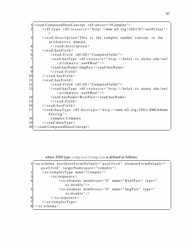
97
✞ ☎1 <cead:ComposedDataConcept r d f : a b o u t =" #Complex ">2 < r d f : t y p e r d f : r e s o u r c e =" h t t p : / /www. w3 . org / 2 0 0 2 / 0 7 / owl# C l a s s " /
>3 < c e a d : d e s c r i p t i o n >This i s t he complex number concep t i n the
a r i t h m e t i c s domain .4 < / c e a d : d e s c r i p t i o n >5 < c e a d : h a s F i e l d >6 < c e a d : F i e l d r d f : I D =" ComplexFie ld1 ">7 < cead :hasType r d f : r e s o u r c e =" h t t p : / / bu la1 . cs . uiowa . edu / owl
/ a r i t h m e t i c . owl# Real " / >8 <cead:hasName>ImgPar t < / cead:hasName>9 < / c e a d : F i e l d >
10 < / c e a d : h a s F i e l d >11 < c e a d : h a s F i e l d >12 < c e a d : F i e l d r d f : I D =" ComplexFie ld2 ">13 < cead :hasType r d f : r e s o u r c e =" h t t p : / / bu la1 . cs . uiowa .edu / owl
/ a r i t h m e t i c . owl# Real " / >14 <cead:hasName> R e a l P a r t < / cead:hasName>15 < / c e a d : F i e l d >16 < / c e a d : h a s F i e l d >17 < c e a d : da t a T ype r d f : d a t a t y p e =" h t t p : / /www. w3 . org / 2 0 01 / XMLSchema
# s t r i n g ">18 complex:Complex19 < / c e a d : da t a T ype >20 < / cead:ComposedDataConcept >✝ ✆
where XSD typecomplex:Complex is defined as follows:✞ ☎1 < xs:schema a t t r i b u t e F o r m D e f a u l t =" q u a l i f i e d " e lementFormDefau l t ="
q u a l i f i e d " ta rge tNamespace =" complex ">2 <xs:complexType name=" Complex ">3 < xs : s e que nc e >4 < x s : e l e m e n t minOccurs =" 0 " name=" R e a l P a r t " t ype ="
x s : d o u b l e " / >5 < x s : e l e m e n t minOccurs =" 0 " name=" ImgPar t " t ype ="
x s : d o u b l e " / >6 < / xs : s e que n c e >7 < / xs :complexType>8 < / xs :schema >✝ ✆

98
After the concept is added to the ontology, it can be used in DAL expressions as
other primitive data concepts are used. Moreover, to accessany field of a variablex of
a composed data concept type, the user uses the syntax:x.fieldName. For example, ifx
is a variable of type Complex, to access its RealPart field, the user writesx.RealPart. A
more complex example is shown in the following listing with SolverC that solves quadratic
equations that have complex solutions:✞ ☎1 c o n c e p t : " SolverC " ;2 d e s c r i p t i o n : " Th is i s an q u a d r a t i c e q u a t i o n s o l v e r w i th complex
s o l u t i o n . " ;34 i n p u t : a : r e a l , b : r e a l , c : r e a l ;5 o u t p u t : r e s u l t : ComplexPair ;6 l o c a l : t : r e a l , u : r e a l , x1 : Complex , x2 : Complex ;78 t = b * b − 4 . 0 * a * c ;9 p r i n t ( t ) ;
10 i f t > 0 . 0 then11 x1 = c o n s t r u c t C ((−b + s q r t ( t ) ) / ( 2 . 0 * a ) , 0 . 0 ) ;12 x2 = c o n s t r u c t C ((−b − s q r t ( t ) ) / ( 2 . 0 * a ) , 0 . 0 ) ;13 e l s e14 u = s q r t (− t ) / ( 2 . 0 * a ) ;15 x1 = c o n s t r u c t C (−b / ( 2 . 0 * a ) , u ) ;16 x2 = c o n s t r u c t C (−b / ( 2 . 0 * a ) , −u ) ;17 e n d i f ;18 r e s u l t . f i r s t = x1 ;19 r e s u l t . second = x2 ;✝ ✆
where (1) ComplexPair is also a composed data concept with the two Complex fields:
first andsecond; (2) constructC is an auxiliary action concept for constructing a com-
plex number written as follows:

99
✞ ☎1 c o n c e p t : " c o n s t r u c t C " ;2 d e s c r i p t i o n : " c o n s t r u c t a complex number from two r e a l numbers ,
t he f i r s t number i s t he r e a l pa r t , t he second number i s t heimag ina ry p a r t . " ;
3 message i n p u t : " i n p u t message " ;4 i n p u t : x : r e a l , y : r e a l ;5 o u t p u t : c : Complex ;6 c . R e a l P a r t = x ;7 c . ImgPar t = y ;✝ ✆
Again, the XML code is automatically generated, mimicking the process of a student learn-
ing to solve quadratic equations.
7.2.2 Creating array data concepts
There are two types of arrays in DAL: Unconstrained array data concept and con-
strained array data concept. A constrained array data concept is wanted if there is a range
for lowerbound and upperbound of the array. Otherwise it is an unconstrained array data
concept. For example,String could be considered as an unconstrained array data con-
cepts ofCharacter. But, a vector of 3-dimensional space is a constrained arraydata
concept.
The DAL syntax for creating a constrained array data conceptis:✞ ☎1 c o n c e p t : "<concept−name>" ;2 d e s c r i p t i o n : "<concept−d e s c r i p t i o n >" ;3 l o c a l : concep t < concept−name> i s4 a r r a y ( lowerbound . . upperbound ) of <base−t ype >5 endconcep t ;✝ ✆

100
The DAL syntax for creating unconstrained array data concept is:✞ ☎1 c o n c e p t : "<concept−name>" ;2 d e s c r i p t i o n : "<concept−d e s c r i p t i o n >" ;3 l o c a l : concep t < concept−name> i s4 a r r a y of <base−t ype > ;5 endconcep t ;✝ ✆
In these definition schemes the <concept-name> is the user name of the array concept,
<base-type> is the type of each element in the array, and <concept-description> is similar
to that ofComposedDataConcept.
For example, when the domain expert wants to have the new dataconcept Vector
of 3-dimensional space to work with linear equations, she can specify it in a file called
vector3d.dal as follows:✞ ☎1 c o n c e p t : " Vector3D " ;2 d e s c r i p t i o n : "3−d i m e ns i ona l space v e c t o r " ;3 l o c a l : concep t Vector3D i s4 a r r a y (1 . . 3) o f r e a l ;5 endconcep t ;✝ ✆
After the user sends this file to the OntologyManager via the commandaddData2Onto,
the followingArrayDataConcept individual is generated in her own ontology:✞ ☎1 < c e a d : C o n s t r a i n e d A r r a y r d f : a b o u t =" h t t p : / / l o c a l h o s t :8 0 8 0 / cuongbk .
owl# Vector3D ">2 < cead :hasBaseType r d f : r e s o u r c e =" h t t p : / / bu la1 . cs . uiowa . edu / owl
/ a r i t h m e t i c . owl# Real " / >3 <cead:hasUpperBound >3< / cead:hasUpperBound >4 <cead:hasLowerBound >1< / cead:hasLowerBound >5 < c e a d : d e s c r i p t i o n >3−d i m e ns i ona l space v e c t o r < /
c e a d : d e s c r i p t i o n >6 < c e a d : da t a T ype > a r i : V e c t o r 3 D < / c e a d : da t a T ype >7 < / c e a d : C o n s t r a i n e d A r r a y >✝ ✆

101
For an unconstrained version of the concept vector, she would write:✞ ☎1 c o n c e p t : " Vector " ;2 d e s c r i p t i o n : "n−d i m e ns i ona l space v e c t o r " ;3 l o c a l : concep t Vector i s4 a r r a y of r e a l ;5 endconcep t ;✝ ✆
and the generated individual should be:✞ ☎1 < c e a d : U nc on s t r a i n e dA r r a y r d f : a b o u t =" h t t p : / / l o c a l h o st : 8 0 8 0 / cuongbk
. owl# Vector ">2 < cead :hasBaseType r d f : r e s o u r c e =" h t t p : / / bu la1 . cs . uiowa . edu / owl
/ a r i t h m e t i c . owl# Real " / >3 < c e a d : d e s c r i p t i o n >n−d i m e ns i ona l space v e c t o r < /
c e a d : d e s c r i p t i o n >4 < c e a d : da t a T ype > a r i : V e c t o r < / c e a d : da t a T ype >5 < / c e a d : U nc on s t r a i ne d A r r a y >✝ ✆
After adding these concept definitions to the ontology, the domain expert can write
DAL algorithms which use these concepts as she would do usingprimitive concepts. To
access thei-th element of an arrayx, the user writes:x[i]. For example, the scalar product
of two Vector3D can be written as:✞ ☎1 c o n c e p t : " product3D " ;2 d e s c r i p t i o n : " compute s c a l a r p r oduc t o f two 3D v e c t o r s . " ;3 i n p u t : v1 : Vector3D , v2 : Vector3D ;4 o u t p u t : p : r e a l ;5 p = ( v1 [ 1 ] ) * ( v2 [ 1 ] ) + ( v1 [ 2 ] ) * ( v2 [ 2 ] ) + ( v1 [ 3 ] ) * ( v2 [ 3 ] ) ;✝ ✆
Finally,n-dimensional vectors can be used in solving linear equationsystem using
HouseHolder reduction method as shown in Appendix C.
102
CHAPTER 8DALSYSTEM
This chapter provides some implementation details about ofthe actual DALSystem.
First, I discuss the deployment details of the DALSystem architecture previously shown in
Figure 1.2, then SADLServlet is introduced, and finally the implementation of DDVM is
sketched. The DALSystem is developed using Java and runs on aUNIX server (at the
serverbula1.cs.uiowa.edu) at the Department of Computer Science at University of
Iowa. The library for ontology manipulation and reasoning is the Apache Jena 2.6.41.
8.1 DALSystem Deployment
The components of a DALSystem for an application domain are shown in Fig-
ure 8.1. The components of this diagram are deployed on two web servers.
DAL Console: allows the user to interact with logical concepts in her ontology space in-
cluding her private and shared ontologies.
DAL Translator: translates user DAL expressions into intermediate language called SADL.
DDVM: receives the SADL expression, executes it and returns result to the caller.
Ontology Manager: is responsible for managing user private ontology such as adding
new concepts and removing concepts from user’s private ontology. It also provides
the look up service for other components like DAL Translatorand DDVM.
SADL Servlet: serves as a wrapper around DDVM component so that the outsideworld
can interact with user concepts like normal web services viaSOAP protocol.
1Available at http://jena.apache.org/

10
3
Figure 8.1: DALSystem components deployment
104
The components contained in the web server on the left hand side of the component
diagram form a complete DALSystem in the user private space where their interactions
have already been discussed in section 1.4 The components depicted in the Web server
on the right hand side show how a user concept can be reused like a normal web service.
When the user adds a new concept into her ontologies (privateor shared ones), the Ontol-
ogy Manager translates her DAL expression to SADL expression and stored in her private
space. The URI for accessing the SADL expression is then published as a web service via a
WSDL file. This SADL expression can then be accessed for execution by another DDVM
via the SADL Servlet as presented in section 8.2.
Even though a DALSystem can be deployed to a local network, itis recommended
to be deployed to a cloud computing environment where high speed Internet connection and
on-demand computing resource scalability are provided. These are ideal conditions for vir-
tual machines operating on a network like our DDVM. We assumethat the cloud computing
environment which hosts the DALSystem would have an administration system to manage
user accounts and use a subscription model for operation as suggested in (Rus 2013). The
user administration system allows various users to register for the DALSystem use on a
given problem domain. After registering for an account, each user is granted access to do-
main expert ontologies (DEO) and all computational artifacts associated with concepts in
these ontologies. A private user space is also provided for the user to store her own ontol-
ogy (UOO). The user subscription for a domainD will activate the DALSystem installation
procedure with the required domain ontology. After that theuser can use the domain con-
cepts from provided ontologies or can evolve the problem domain she subscribed for with

105
new concepts she learned and/or created during her own problem solving process as dis-
cussed in Chapter 7. The DALSystem manager could also offer to buy the knowledge
developed by the user and update the domain ontology, thus ensuring domain evolution
with new concepts developed by the respective user. When theuser decides to cancel her
subscription and leave the system, she can also offer to sellher concepts to the DALSys-
tem manager in order to retain these concepts for later use. This evolution model ensures
the domain knowledge expanded by knowledge gains from all domain experts during their
problem solving processes.
The diagram in Figure 8.2, a slightly modified version of Figure 2 in (Rus 2013),
illustrates clearly this cloud implementation of the DALSystem. In this diagram, the Cloud
Administrator is represented as the smiling face on the top.There arek domain users at the
bottom whose activities are numbered according to their sequence, with the first activity is
subscribing to the DALSystem. The next activity is the installation of the DALSystem onto
the user’s space. Then the user can use her concepts via the DAL Console. The fourth step
is to evolve the user own ontology. Finally, the user can publish her concepts to the shared
domain expert ontology in the fifth activity.
8.2 SADL Servlet
SADL Servlet is a Java Servlet (Mordani 2009) which is a service wrapper for
DDVM so that it helps the DDVM communicate with the outside world via SOAP protocol
just like normal web services. The SADL Servlet was designedto allow one DDVM to in-
voke another DDVM without any special distinction with other SOAP-based web services.

106
✫✪✬✩❝❝
Cloud
❄2. Install DAL System
❄❄
✬
✫
✩
✪DDVM: SADL ✲Execute
Network
DAL Algorithm ✲ DAL Translator ✛ DAL Specs
Domain Ontology
❄
✎✍ ☞✌User1
❄4. Evolve OWL(DAL)
✻
3. Use DAL
✲5. Publishontology
✲1. Subscribe for
DAL
. . .✎✍ ☞✌Userk
❄4. Evolve OWL(DAL)
✻
3. Use DAL
✛ 5. Publishontology
✛ 1. Subscribe for
DAL
User1’s ownontology
Userk’s ownontology
Figure 8.2: Cloud Implementation of the DALSystem

107
This design also allows a DDVMV1 to execute remote SADL code without downloading
that SADL code to the local DDVMV1. Thus, we achieve two goals:
1. Improve the security of the SADL code so that the user can confidently share their
services without worrying about losing their implementation ideas.
2. The SADL code is executed where it is deployed. That means all the configuration
settings and dependencies are in place.
The process of invoking an action concept as a normal web service via the SADL Servlet
starts when a DDVM makes a SOAP call to an URI where the SADL Servlet is listening.
Based on the request URI, the SADL Servlet retrieves the corresponding SADL expression
for the requested service of the action concept. Then, a DDVMis spawned in a new thread
by the SADL Servlet and then the DDVM loads the SADL expression into its memory.
SADL Servlet analyzes the SOAP request once again to retrieve the input data and transfers
it to the DDVM before executing the SADL code. After the execution finishes, the SADL
Servlet retrieves the result and returns it back to the initial DDVM as a SOAP response
message.
Since the time for creating a DDVM from a SADL file is significant when the
ontology is large, it would be inefficient if SADLServlet hasto reconstruct a DDVM every
time a request comes and destroys the DDVM after that. A solution to make the system
more efficient would be to cache the DDVM for each invoked concept. The cache value
will be refreshed if the content of the concept is updated, i.e. the SADL code of the concept.
Using this technique, the DALSystem reduces the overall execution time by about 3 times.

108
8.3 Implementation of DDVM
The rationale for virtual machines like DDVM is that they arevirtual processors
which can provide a common execution platform for one or moreDALs in a hardware-
independent way. There are several approaches to implementvirtual machines (Craig
2006):
• Direct implementation;
• Translation;
• Threaded code.
In this thesis the author chooses to use the direct implementation approach. How-
ever, the platform which executes DDVM instructions is a Java Virtual Machine (JVM). We
choose JVM to maximize the capability of DDVM to execute on asmany hardware plat-
forms as possible without worrying about the variety of hardware processors. In that light,
each “computational concept call” instruction (for executing a concept) will be directly ex-
ecuted by a JVM. JVM will make a SOAP call to the remote web service implementing
the semantics of the corresponding domain concept. The current execution thread of the
DDVM is blocked and waits for the result from the remote server. The remote server will
create a process executing the corresponding domain concept executable code (semantics).
The result of the call will be pushed back to TOS (Top of Stack)of the local execution
scope. The execution thread of the DDVM is notified to continue.
During the execution process, if a domain action concept is encountered, the DDVM
will dynamically download the WSDL file of the targeted web service to extract informa-
tion about parameter names to compose the SOAP message correctly. Therefore, if it has

109
to download and parse the WSDL every time an action concept isexecuted, it will be very
inefficient. Since the WSDL file hardly changes during the lifetime of a web service de-
ployment, DDVM will only download and parse the WSDL file the first time; it will cache
the WSDL parse in its memory until it is destroyed. This caching method speeds up the
DDVM and reduce the execution time about 3 times.

110
CHAPTER 9CONCLUSIONS
The DALSystem was set out to explore the concept identified in“Liberating Com-
puter User from Programming” (Rus 2008) through a creation of a prototype system. This
research has sought to answer two questions:
1. Can we develop a system to be used by a domain expert to integrate computers into
her problem solving process?
2. If so, can we demonstrate the system with a particular domain?
This thesis provides affirmative answers to these two questions by the implemen-
tation of the DALSystem as a demonstration of integrating computers into the problem
solving process of the domain of arithmetic, high-school algebra and vector algebra.
The implementation of the DALSystem for the domain of arithmetic allows domain
users to express their computations using domain specific terms and phrases while provid-
ing seamless execution of the computation on the network across organization boundaries
based on web services composition. The language can be used naturally by domain users
because its vocabulary and phrases are characteristic to the domain of arithmetic. The
language is also algorithmic because ambiguities of the language arithmeticians use are
eliminated by the arithmetic context.
This thesis also proposed a mechanism for the domain user to evolve the domain
ontology with new action and data concepts. This mechanism of automating the process
of associating computational artifacts with new domain concepts will help domain users

111
easily expand their ontologies during the problem solving process from a small set of initial
primitive concepts.
In this thesis, we also experiemented with the idea of putting data composition
information into ontological knowledge base. Such information is vital for the system to
provide better input/output handling experience in an interactive mode with domain users.
All the accomplishments discussed above show the potentialof the DALSystem.
However, there are several problems to be addressed in future research.
The DALSystem is a demonstration of our domain-oriented methodology for the
domain of arithmetic. Arithmetic is a well-defined domain which has been studied for
thousand years, so it was relatively easy to implement the concept. There are new emerg-
ing fields of study that are not very well-defined such as bioinformatics or computational
linguistics. Therefore, a better experiment would be an implementation of our methodol-
ogy for the domain of bioinformatics and/or computational linguistics using Web systems.
The incremental nature of the domain ontology makes us believe that breaking the domain
thinking inertia is the major problem in front of such experiments.
The DALSystem is currently implemented to work with web services using the
SOAP protocol. Even though the SOAP protocol is a well-defined standard, it results in
a large overhead for SOAP messages. On the other hand, REST (Erl, Balasubramanian,
Carlyle & Pautasso 2012) is a light-weighted protocol without the cost overhead. So im-
plementing a DALSystem to work with the REST protocol is a worthy research direction
for the future.

112
The system implementation suffers from lack of efficiency compared to traditional
compiled programs running on local machines. This is mainlybecause most of the execu-
tion times of the experimented concepts are much smaller compared to the communication
overhead time. Another reason for lack of efficiency is the sequential implementation of
the process of composing web services. After the DDVM sends out a SOAP request, it
waits for the response from the server. The execution process can be actually accelerated if
the DDVM executes concepts in parallel.
The current implementation of DDVM for web services composition is very simple
without any execution optimization. In future research, weneed to develop better algo-
rithms for web services execution planning with respect to the following criteria: speed of
execution, speed of connection, and cost to run.
Despite of these problems, the DALSystem has shown that it ispossible to inte-
grate computers seamlessly into the human problem solving process so that the domain
users can perform their computation at the domain logical level without worrying about the
underlying computer systems.

113
APPENDIX ADALSYSTEM USER MANUAL
A.1 Introduction
The DALSystem is a brain assistant which allows computer users to interact with
their concepts in domain ontologies. These concepts are linked with their implementation
artifacts such as web services so that the users can perform their computation. A user can
interact with her Ontology Manager via a program called DALConsole. This program can
look up concepts in user ontology and help the user execute them.
After you have logged in to the system, you can use the tutorial in the following
section to play with your concepts.
A.2 DALConsole Tutorial
A.2.1 Getting Started
The best way to learn a language is to write the Hello World.
In DALConsole, after the prompt, you type:
> print("Hello World!");
It will print
Hello World!
To list all the concepts in your ontology, type:
>list
The user can query information about her concept by the command

114
>info <concept name>
For example, if the user wants to know more about the conceptgcd, she can type:✞ ☎1 > i n f o gcd2 Concept D e s c r i p t i o n : Th is i s t he f u n c t i o n t o f i n d g r e a t e s tcommon
d i v i s o r (GCD)3 of two i n t e g e r s . I t i s implemented us i ng E u c l i d i a n a l g o r i th m .4 I npu t i n f o r m a t i o n : NONE5 P a r a m e t e r s I n f o r m a t i o n : There a r e 2 pa r a m e t e r ( s ) .6 Paramete r a of t ype h t t p : / / bu la1 . cs . uiowa . edu / owl / a r i th m e t i c . owl#
I n t e g e r7 Paramete r b of t ype h t t p : / / bu la1 . cs . uiowa . edu / owl / a r i th m e t i c . owl#
I n t e g e r✝ ✆
To call a concept, e.g.gcd, you write the concept name followed by the list of
input parameters for that concept. For example, to call the conceptgcd with two input
parameters,28 and42, you type after the DALConsole prompt:
>gcd(28, 42)
14
You should get the answer of14.
A.2.2 Variables and Arithmetic Expressions
Variables are declared using the following syntax
varName: type;
For example,
> x: integer;
> y: real;

115
In the domain of Arithmetic on Bula1, there are currently 4 types of primitive data concepts:
• integer
• real
• string
• boolean: for logical values (true, false)
After you declared a variable, you can use it in your computation. Arithmetic oper-
ators provided in DALConsole are:
+,−, ∗, / arithmetic operators for integer, real valuesand, or, not logical operators for boolean==,=, <,> comparison operators for arithmetic expressions
Table A.1: DAL operators
So you can type after the prompt:
> 1 + 1
2
> 4.5 * 9.0
40.5
> 3.6 / 9.0
0.4
Notice that there is no semi colon after these expressions.
With variables, you can assign values to them by the operator“=”:

116
> z: integer;
> z = 16 * 23 - 4 / 2;
> print(z);
366
You can also print variable value just by typing the variablename without a semi colon at
the end.
> z
366
A.2.3 Arrays
DALConsole currently doesn’t allow you to create a new arraytype (you can create
one using the addData2Onto command though). But you can use existing array type such
as Vector (an array of 3 real numbers). To construct a vector variable with three elements
1.5, 2.4, 3.6, you type in:
> t: Vector;
> t = {1.5, 2.4, 3.6};
You can then print the content just like other variables by typing:
> print(t);
[1.5, 2.4, 3.6,]
Or simply

117
> t
[1.5, 2.4, 3.6,]
To access the i-th element of a vector (array), you use the [...] operator. For exam-
ple, to get the second element of the vectort, you type
> t[2]
2.4
The system should print the value of the second element oft which is 2.4.
Now let’s compute the length of vectort.
> sqrt(t[1] * t[1] + t[2] * t[2] + t[3] * t[3])
4.178516483155236
Now we can test the matrix with HouseHolderReduce algorithm. For example, if
you want to solve the following linear equation system:
2.0 2.0 4.01.0 3.0 1.03.0 1.0 3.0
x =
18.01.014.0
Ax = b
In HouseHolderReduce algorithm, vectors are columns of thematrix. So in DALConsole,
you type:
> a: Matrix;
> b: Vector;
> x: Vector;

118
> a[1] = {2.0, 1.0, 3.0};
> a[2] = {2.0, 3.0, 1.0};
> a[3] = {4.0, -2.0, 3.0};
> b = {18.0, 1.0, 14.0};
> x = HouseHolderReduce(a, b, 3);
A.3 DAL Language Tutorial
To go beyond the normal usage of DALConsole and create your own concept, you
need to learn the DAL Language for Arithmetic Domain. There are two common types of
concepts in one’s computation domain: data concepts and action concepts. Data concepts
such as integer, real, vector, etc. are concepts which hold data. Action concepts such as
gcd, add, multiply, etc. manipulate data concepts and produce output results. The following
sections will instruct you to create such concepts.
A.3.1 Creating action concepts
To create a action concept of your own, say addition of two vectors, there are two
steps you need to do:
1. Write the description of your algorithm in a text file usingan editor (such asvi),
saysaddV.dal, then
2. From DALConsole prompt, you type the command,
>add2Onto addV.dal

119
For example, the content of the algorithm for adding two vectors can be written as
follows:✞ ☎1 concep t : " addV " ;2 d e s c r i p t i o n : " Th is i s t he concep t o f add ing two v e c t o r s . " ;3 message i n p u t : " P l e a s e e n t e r two v e c t o r s . " ;4 i n p u t : v1 : Vector , v2 : Vector ;5 o u t p u t : v : Vector ;6 l o c a l : i : i n t e g e r ;78 f o r i = 1 ; i f i <= 39 begin
10 v [ i ] = v1 [ i ] + v2 [ i ] ;11 end12 wi thNext i = i + 1 ;✝ ✆
In this file, the first two lines are required to provide description about your concept. The
third line is optional for displaying input information when a user requests information
about this concept.
The next three lines (4 – 6) are optional for declaring the input, output and local
variables that you may want to use in the algorithm. In each line, variable descriptions are
separated by a comma and the whole line ends with a semicolon.So the line 4 means, your
algorithm has two input parameters, v1, v2, of the typeVector.
After that is the main body of your algorithm. In this case there is a for-loop which
compute the sum of two vectors v1 and v2. The details of this for-loop will be discussed
later in section A.3.2.2.
You can then add this concept to your ontology using the DALConsole program
with the command
>add2Onto addV.dal

120
After that you should use thelist command to check if the conceptaddV is
correctly added to your ontology. You can also query the information about this concept by
typing:
>info addV
Concept Description: This is the concept of adding two vectors.
Input information: Please enter two vectors.
Parameters Information: There are 2 parameter(s).
Parameter v1 of type http://localhost:8080/cuongbk.owl#Vector
Parameter v2 of type http://localhost:8080/cuongbk.owl#Vector
Now let’s use this concept to add two vectors x = {1.0, 2.0, 3.0} and y = {4.0, 5.0,
6.0}.
>x: Vector;
>x = {1.0, 2.0, 3.0};
>y: Vector;
>y = {4.0, 5.0, 6.0};
>z: Vector;
>z = addV(x, y);
>print(z);
[5.0,7.0,9.0,]

121
A.3.2 Control-flow constructs
A.3.2.1 If-then
Formally, the syntax forif-then construct is
if expr then
statement1(s);
else
statement2(s);
endif;
Whereexpr is a boolean expression. Ifexpr is evaluated to true, thenstatement1(s)
are executed. Otherwise,statement2(s) are executed. Theelsebranch is optional.
For example,
if n < 3 then
z = a;
else
z = b;
endif;
A.3.2.2 While and For
In thewhile-loop construct of
while expr do
statement(s);
endwhile;

122
if the boolean expressionexpr is evaluated totrue, thestatement(s) is executed
and the expression is re-evaluated. This cycle repeats until expr becomesfalse.
For example, the Euclidean algorithm for finding gcd of two integers a, b are ex-
pressed bywhile-loop as follows:
while b != 0 do
t = b;
b = a % b;
a = t;
print(a);
endwhile;
Thefor-loop has the formal syntax as:
for expr1; if expr2
begin
statement(s);
end
withNext expr3;
which is equivalent to
expr1;
while expr2 do
statement(s);
expr3;

123
endwhile;
For example, the addition of two vectors can be written as
for i = 1; if i <= 3
begin
v[i] = v1[i] + v2[i];
end
withNext i = i + 1;
A.3.3 Creating data concepts
To create a new data concept, sayVector, similarly to action concepts, there are
also two steps you need to do:
1. Write the description of your data concept in a text file, say vector.dal, then
2. From DALConsole prompt, you type the command,
>addData2Onto vector.dal
Even though the two steps are very similar to those of action concepts, the key dif-
ference is the commandaddData2Onto instead ofadd2Onto (without keyword
Data).
There are two types of composed data concepts:arrays andrecords.
A.3.3.1 Data concepts of Array type
TheVector concept is an array of real numbers. The formal syntax for declaring
an array type is

124
concept <name> is
array (lowerbound .. upperbound) of <base-type>;
endconcept;
where<name> is the concept name,lowerbound, upperbound are integer numbers
specifying the range of indexes,<base-type> is the type of each element in the array.
For example theVector concept in 3D space is defined as
concept Vector is
array (1 .. 3) of real;
endconcept;
The whole vector.dal file looks like✞ ☎1 concep t : " Vector " ;2 d e s c r i p t i o n : " Vector t ype " ;3 l o c a l :4 concep t Vector i s5 array (1 . . 3 ) of r e a l ;6 endconcep t ;✝ ✆
The first two lines are required to describe the concept.
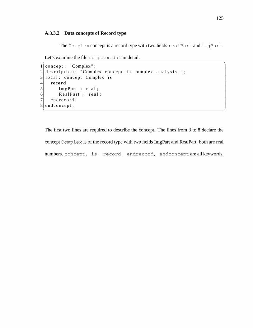
125
A.3.3.2 Data concepts of Record type
TheComplex concept is a record type with two fieldsrealPart andimgPart.
Let’s examine the filecomplex.dal in detail.✞ ☎1 concep t : " Complex " ;2 d e s c r i p t i o n : " Complex concep t i n complex a n a l y s i s . " ;3 l o c a l : concep t Complexi s4 record5 ImgPar t : r e a l ;6 R e a l P a r t : r e a l ;7 e nd r e c o r d ;8 endconcep t ;✝ ✆
The first two lines are required to describe the concept. The lines from 3 to 8 declare the
conceptComplex is of the record type with two fields ImgPart and RealPart, both are real
numbers.concept, is, record, endrecord, endconcept are all keywords.

126
APPENDIX BCEAD ONTOLOGY OWL FILE
Listing B.1: Action conceptadd definition in OWL✞ ☎1 <?xml v e r s i o n =" 1 . 0 " ?>2 < r d f :RDF3 xmlns : r d f =" h t t p : / / www. w3 . org /1999/02/22− rd f−syntax−ns # "4 xmlns : p r o t e g e =" h t t p : / / p r o t e g e . s t a n f o r d . edu / p l u g i n s/ owl /
p r o t e g e # "5 xmlns : xsp=" h t t p : / / www. owl−o n t o l o g i e s . com / 2 0 0 5 / 0 8 / 0 7 / xsp . owl# "6 xmlns =" h t t p : / / bu la1 . cs . uiowa . edu / owl / cead . owl# "7 xmlns : owl=" h t t p : / / www. w3 . org / 2 0 0 2 / 0 7 / owl# "8 xmlns : p1=" h t t p : / / www. daml . org / s e r v i c e s / owl−s / 1 . 1 / P r o f i l e . owl#
"9 xmlns : xsd=" h t t p : / / www. w3 . org / 2 0 0 1 / XMLSchema# "
10 xmlns : swr l =" h t t p : / / www. w3 . org / 2 0 0 3 / 1 1 / swr l # "11 xmlns : swr lb =" h t t p : / / www. w3 . org / 2 0 0 3 / 1 1 / swr lb # "12 xmlns : r d f s =" h t t p : / / www. w3 . org / 2 0 0 0 / 0 1 / rd f−schema # "13 xml : base =" h t t p : / / bu la1 . cs . uiowa . edu / owl / cead . owl ">1415 <owl : C l a s s r d f : ID=" Act ionConcep t " / >16 <owl : C l a s s r d f : ID=" F i l t e r C o n c e p t " >17 < r d f s : subClassOf r d f : r e s o u r c e =" # Act ionConcep t " / >18 </ owl : C lass >19 <owl : C l a s s r d f : ID=" DataConcept " / >20 <owl : C l a s s r d f : ID=" ComposedDataConcept ">21 < r d f s : subClassOf r d f : r e s o u r c e =" # DataConcept " / >22 </ owl : C lass >23 <owl : C l a s s r d f : ID=" U nc ons t r a i ne dA r r a y ">24 < r d f s : subClassOf r d f : r e s o u r c e =" # DataConcept " / >25 </ owl : C lass >26 <owl : C l a s s r d f : ID=" C ons t r a i ne dA r r a y ">27 < r d f s : subClassOf r d f : r e s o u r c e =" # U nc ons t r a i ne dA r r a y" / >28 </ owl : C lass >29 <owl : C l a s s r d f : ID=" P r i m i t i ve D a t a C onc e p t ">30 < r d f s : subClassOf r d f : r e s o u r c e =" # DataConcept " / >31 </ owl : C lass >32 <owl : C l a s s r d f : ID=" F i e l d " / >33 <owl : C l a s s r d f : ID=" Concept ">34 <owl : unionOf r d f : parseType =" C o l l e c t i o n ">35 <owl : C l a s s r d f : abou t =" # DataConcept " / >36 <owl : C l a s s r d f : abou t =" # Act ionConcept " / >37 </ owl : unionOf >✝ ✆

127
Listing B.1 continued✞ ☎38 </ owl : C lass >39 <owl : O b j e c t P r o p e r t y r d f : ID=" i n p u t F i l t e r ">40 < r d f s : domain r d f : r e s o u r c e =" # DataConcept " / >41 < r d f s :range r d f : r e s o u r c e =" # Act ionConcept " / >42 </ owl : O b j e c t P r ope r t y >43 <owl : O b j e c t P r o p e r t y r d f : ID=" o u t p u t F i l t e r ">44 < r d f s : domain r d f : r e s o u r c e =" # DataConcept " / >45 < r d f s :range r d f : r e s o u r c e =" # Act ionConcept " / >46 </ owl : O b j e c t P r ope r t y >47 <owl : C l a s s r d f : ID=" I npu t " / >48 <owl : C l a s s r d f : ID=" S e r v i c e I n s t a n c e " / >49 <owl : C l a s s r d f : ID=" Agent " / >50 <owl : O b j e c t P r o p e r t y r d f : ID=" hasOutpu t ">51 < r d f s : domain r d f : r e s o u r c e =" # Act ionConcep t " / >52 < r d f s :range r d f : r e s o u r c e =" # DataConcept " / >53 <owl : i nve rseOf >54 <owl : O b j e c t P r o p e r t y r d f : ID=" o u t p u t " / >55 </ owl : i nve rseOf >56 </ owl : O b j e c t P r ope r t y >57 <owl : O b j e c t P r o p e r t y r d f : ID=" h a s I n p u t ">58 < r d f s : domain r d f : r e s o u r c e =" # Act ionConcep t " / >59 < r d f s :range r d f : r e s o u r c e =" # I npu t " / >60 </ owl : O b j e c t P r ope r t y >61 <owl : O b j e c t P r o p e r t y r d f : ID=" inpu tType ">62 < r d f s : domain r d f : r e s o u r c e =" # I npu t " / >63 < r d f s :range r d f : r e s o u r c e =" # DataConcept " / >64 </ owl : O b j e c t P r ope r t y >65 <owl : O b j e c t P r o p e r t y r d f : ID=" implementedBy ">66 < r d f s : domain r d f : r e s o u r c e =" # Agent " / >67 < r d f s :range r d f : r e s o u r c e =" # S e r v i n c e I n s t a n c e " / >68 </ owl : O b j e c t P r ope r t y >69 <owl : D a t a t y p e P r o p e r t y r d f : ID=" inputName ">70 < r d f s : domain r d f : r e s o u r c e =" # I npu t " / >71 < r d f s :range r d f : r e s o u r c e =" h t t p : / / www. w3 . org / 2 0 0 1 / XMLSchema#
s t r i n g " / >72 </ owl : D a t a t ype P r ope r t y >73 <owl : D a t a t y p e P r o p e r t y r d f : ID=" o r de r ">74 < r d f s : domain r d f : r e s o u r c e =" # I npu t " / >75 < r d f s :range r d f : r e s o u r c e =" h t t p : / / www. w3 . org / 2 0 0 1 / XMLSchema#
i n t " / >76 </ owl : D a t a t ype P r ope r t y >77 <owl : O b j e c t P r o p e r t y r d f : ID=" hasAgent ">78 < r d f s : domain r d f : r e s o u r c e =" # Act ionConcep t " / >79 < r d f s :range r d f : r e s o u r c e =" #Agent " / >✝ ✆

128
Listing B.1 continued✞ ☎80 </ owl : O b j e c t P r ope r t y >81 <owl : D a t a t y p e P r o p e r t y r d f : ID=" d e s c r i p t i o n ">82 < r d f s : domain r d f : r e s o u r c e =" # Concept " / >83 < r d f s :range r d f : r e s o u r c e =" h t t p : / / www. w3 . org / 2 0 0 1 / XMLSchema#
s t r i n g " / >84 </ owl : D a t a t ype P r ope r t y >85 <owl : D a t a t y p e P r o p e r t y r d f : ID=" inpu tMessage ">86 < r d f s : domain r d f : r e s o u r c e =" # Act ionConcep t " / >87 < r d f s :range r d f : r e s o u r c e =" h t t p : / / www. w3 . org / 2 0 0 1 / XMLSchema#
s t r i n g " / >88 </ owl : D a t a t ype P r ope r t y >89 <owl : D a t a t y p e P r o p e r t y r d f : ID=" outputMessage ">90 < r d f s : domain r d f : r e s o u r c e =" # Act ionConcep t " / >91 < r d f s :range r d f : r e s o u r c e =" h t t p : / / www. w3 . org / 2 0 0 1 / XMLSchema#
s t r i n g " / >92 </ owl : D a t a t ype P r ope r t y >93 <owl : D a t a t y p e P r o p e r t y r d f : ID=" dataType ">94 < r d f s : domain r d f : r e s o u r c e =" # DataConcept " / >95 < r d f s :range r d f : r e s o u r c e =" h t t p : / / www. w3 . org / 2 0 0 1 / XMLSchema#
s t r i n g " / >96 </ owl : D a t a t ype P r ope r t y >97 <owl : D a t a t y p e P r o p e r t y r d f : ID=" hasName ">98 < r d f s : domain r d f : r e s o u r c e =" # F i e l d " / >99 < r d f s :range r d f : r e s o u r c e =" h t t p : / / www. w3 . org / 2 0 0 1 / XMLSchema#
s t r i n g " / >100 </ owl : D a t a t ype P r ope r t y >101 <owl : O b j e c t P r o p e r t y r d f : ID=" hasType ">102 < r d f s : domain r d f : r e s o u r c e =" # F i e l d " / >103 < r d f s :range r d f : r e s o u r c e =" # DataConcept " / >104 </ owl : O b j e c t P r ope r t y >105 <owl : O b j e c t P r o p e r t y r d f : ID=" h a s F i e l d ">106 < r d f s : domain r d f : r e s o u r c e =" # ComposedDataConcept " />107 < r d f s :range r d f : r e s o u r c e =" # F i e l d " / >108 </ owl : O b j e c t P r ope r t y >109 <owl : O b j e c t P r o p e r t y r d f : ID=" hasBaseType ">110 < r d f s : domain r d f : r e s o u r c e =" # U nc ons t r a i ne dA r r a y " / >111 < r d f s :range r d f : r e s o u r c e =" # DataConcept " / >112 </ owl : O b j e c t P r ope r t y >113 <owl : D a t a t y p e P r o p e r t y r d f : ID=" hasLowerBound ">114 < r d f s : domain r d f : r e s o u r c e =" # C ons t r a i ne dA r r a y " / >115 < r d f s :range r d f : r e s o u r c e =" h t t p : / / www. w3 . org / 2 0 0 1 / XMLSchema#
i n t " / >116 </ owl : D a t a t ype P r ope r t y >117 <owl : D a t a t y p e P r o p e r t y r d f : ID=" hasUpperBound ">✝ ✆

129
Listing B.1 continued✞ ☎118 < r d f s : domain r d f : r e s o u r c e =" # C ons t r a i ne dA r r a y " / >119 < r d f s :range r d f : r e s o u r c e =" h t t p : / / www. w3 . org / 2 0 0 1 / XMLSchema#
i n t " / >120 </ owl : D a t a t ype P r ope r t y >121 <owl : F u n c t i o n a l P r o p e r t y r d f : ID=" serv iceName ">122 < r d f :type r d f : r e s o u r c e =" h t t p : / / www. w3 . org / 2 0 0 2 / 0 7 / owl#
D a t a t y p e P r o p e r t y " / >123 < r d f s : domain r d f : r e s o u r c e =" # S e r v i c e I n s t a n c e " / >124 < r d f s :range r d f : r e s o u r c e =" h t t p : / / www. w3 . org / 2 0 0 1 / XMLSchema#
s t r i n g " / >125 </ owl : F u n c t i o n a l P r o p e r t y >126 <owl : F u n c t i o n a l P r o p e r t y r d f : ID=" w s d l F i l e ">127 < r d f s :range r d f : r e s o u r c e =" h t t p : / / www. w3 . org / 2 0 0 1 / XMLSchema#
s t r i n g " / >128 < r d f s : domain r d f : r e s o u r c e =" # S e r v i c e I n s t a n c e " / >129 < r d f :type r d f : r e s o u r c e =" h t t p : / / www. w3 . org / 2 0 0 2 / 0 7 / owl#
D a t a t y p e P r o p e r t y " / >130 </ owl : F u n c t i o n a l P r o p e r t y >131 <owl : F u n c t i o n a l P r o p e r t y r d f : ID=" u r i ">132 < r d f s :range r d f : r e s o u r c e =" h t t p : / / www. w3 . org / 2 0 0 1 / XMLSchema#
s t r i n g " / >133 < r d f s : domain r d f : r e s o u r c e =" # S e r v i c e I n s t a n c e " / >134 < r d f :type r d f : r e s o u r c e =" h t t p : / / www. w3 . org / 2 0 0 2 / 0 7 / owl#
D a t a t y p e P r o p e r t y " / >135 </ owl : F u n c t i o n a l P r o p e r t y >136 <owl : F u n c t i o n a l P r o p e r t y r d f : ID=" opera t ionName ">137 < r d f s :range r d f : r e s o u r c e =" h t t p : / / www. w3 . org / 2 0 0 1 / XMLSchema#
s t r i n g " / >138 < r d f s : domain r d f : r e s o u r c e =" # S e r v i c e I n s t a n c e " / >139 < r d f :type r d f : r e s o u r c e =" h t t p : / / www. w3 . org / 2 0 0 2 / 0 7 / owl#
D a t a t y p e P r o p e r t y " / >140 </ owl : F u n c t i o n a l P r o p e r t y >141 <owl : F u n c t i o n a l P r o p e r t y r d f : ID=" portName ">142 < r d f :type r d f : r e s o u r c e =" h t t p : / / www. w3 . org / 2 0 0 2 / 0 7 / owl#
D a t a t y p e P r o p e r t y " / >143 < r d f s : domain r d f : r e s o u r c e =" # S e r v i c e I n s t a n c e " / >144 < r d f s :range r d f : r e s o u r c e =" h t t p : / / www. w3 . org / 2 0 0 1 / XMLSchema#
s t r i n g " / >145 </ owl : F u n c t i o n a l P r o p e r t y >146 < P r i m i t i ve D a t a C onc e p t r d f : ID=" S t r i n g ">147 < d e s c r i p t i o n > This i s t he p r i m i t i v e S t r i n g concep t f o r use
with i n p u t f i l t e r .148 </ d e s c r i p t i o n >✝ ✆

130
Listing B.1 continued✞ ☎149 < dataType r d f : d a t a t y p e =" h t t p : / / www. w3 . org / 2 0 0 1 / XMLSchema#
s t r i n g ">150 xsd : s t r i n g151 </ dataType >152 </ P r i m i t i ve D a t a C onc e p t >153 < U nc ons t r a i ne dA r r a y r d f : ID=" S t r i n g A r r a y ">154 < d e s c r i p t i o n > This i s t he p r i m i t i v e S t r i n g array concep t f o r
use with i n p u t f i l t e r .155 </ d e s c r i p t i o n >156 <hasBaseType r d f : r e s o u r c e =" # S t r i n g " / >157 </ Uncons t ra inedAr ray >158 </ r d f : RDF>159160 <!−− Created w i th P ro tege ( w i th OWL P lug in 3 . 3 . 1 , B u i l d 430)
h t t p : / / p r o t e ge . s t a n f o r d . edu−−>✝ ✆
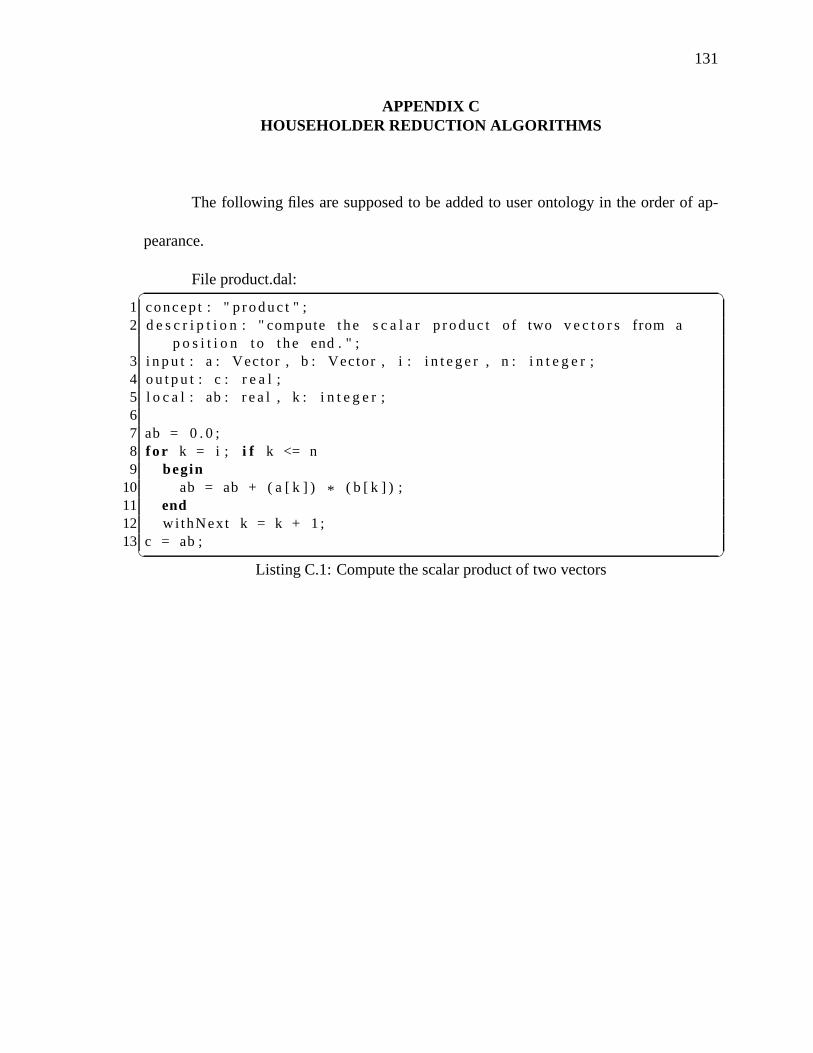
131
APPENDIX CHOUSEHOLDER REDUCTION ALGORITHMS
The following files are supposed to be added to user ontology in the order of ap-
pearance.
File product.dal:✞ ☎1 concep t : " p r oduc t " ;2 d e s c r i p t i o n : " compute t he s c a l a r p r oduc t o f two v e c t o r s from a
p o s i t i o n t o t he end . " ;3 i n p u t : a : Vector , b : Vector , i : i n t e g e r , n : i n t e g e r ;4 o u t p u t : c : r e a l ;5 l o c a l : ab : r e a l , k : i n t e g e r ;67 ab = 0 . 0 ;8 f o r k = i ; i f k <= n9 begin
10 ab = ab + ( a [ k ] ) * ( b [ k ] ) ;11 end12 wi thNext k = k + 1 ;13 c = ab ;✝ ✆
Listing C.1: Compute the scalar product of two vectors

132
File eliminate.dal:✞ ☎1 concep t : " e l i m i n a t e " ;2 d e s c r i p t i o n : " Compute HouseHolder e l i m i n a t i o n . " ;3 i n p u t : a i : Vector , v i : Vector , i : i n t e g e r , n : i n t e g e r ;4 o u t p u t : c : Vector ;5 l o c a l : anorm : r e a l , d i i : r e a l , f i : r e a l , w i i : r e a l , k : i n t e ge r ;6 anorm = s q r t ( p r oduc t ( a i , a i , i , n ) ) ;7 i f a i [ i ] > 0 . 0 then8 d i i = −anorm ;9 e l s e
10 d i i = anorm ;11 e n d i f ;12 w i i = a i [ i ] − d i i ;13 f i = s q r t (−2.0 * w i i * d i i ) ;14 v i [ i ] = w i i / f i ;15 a i [ i ] = d i i ;1617 f o r k = i + 1 ; i f k <= n18 begin19 v i [ k ] = a i [ k ] / f i ;20 a i [ k ] = 0 . 0 ;21 end22 wi thNext k = k + 1 ;2324 c = a i ;✝ ✆
Listing C.2: HouseHolder elimination concept

133
File eliminate2.dal:✞ ☎1 concep t : " e l i m i n a t e 2 " ;2 d e s c r i p t i o n : " Compute HouseHolder e l i m i n a t i o n . " ;3 i n p u t : a i : Vector , v i : Vector , i : i n t e g e r , n : i n t e g e r ;4 o u t p u t : c : Vector ;5 l o c a l : anorm : r e a l , d i i : r e a l , f i : r e a l , w i i : r e a l , k : i n t e ge r ;6 anorm = s q r t ( p r oduc t ( a i , a i , i , n ) ) ;7 i f ( a i [ i ] ) > 0 . 0 then8 d i i = −anorm ;9 e l s e
10 d i i = anorm ;11 e n d i f ;12 w i i = ( a i [ i ] ) − d i i ;13 f i = s q r t (−2.0 * w i i * d i i ) ;14 v i [ i ] = w i i / f i ;15 a i [ i ] = d i i ;1617 f o r k = i + 1 ; i f k <= n18 begin19 v i [ k ] = a i [ k ] / f i ;20 a i [ k ] = 0 . 0 ;21 end22 wi thNext k = k + 1 ;23 c = v i ;✝ ✆
Listing C.3: HouseHolder elimination concept
File transform.dal:✞ ☎1 concep t : " t r a n s f o r m " ;2 d e s c r i p t i o n : " HouseHolder t r a n s f o r m a t i o n concep t . " ;3 i n p u t : a j : Vector , v i : Vector , i : i n t e g e r , n : i n t e g e r ;4 o u t p u t : c : Vector ;5 l o c a l : f i : r e a l , k : i n t e g e r ;67 f i = 2 . 0 * p r oduc t ( v i , a j , i , n ) ;8 f o r k = i ; i f k <= n9 begin
10 a j [ k ] = ( a j [ k ] ) − f i * ( v i [ k ] ) ;11 end12 wi thNext k = k + 1 ;13 c = a j ;✝ ✆
Listing C.4: HouseHolder transformation concept

134
File houseHolderReduce.dal:✞ ☎1 concep t : " HouseHolderReduce " ;2 d e s c r i p t i o n : " HouseHolder L i ne a r Equa t ion System S o l ve rconcep t . "
;3 i n p u t : a : Matr ix , b : Vector , n : i n t e g e r ;4 o u t p u t : x : Vector ;5 l o c a l : v i : Vector , i : i n t e g e r , j : i n t e g e r , t 1 : Vector , t 2 : Vector
, t : r e a l , u : r e a l ;67 f o r i = 1 ; i f i <= n8 begin9 v i [ i ] = 0 . 0 ;
10 end11 wi thNext i = i + 1 ;1213 f o r i = 1 ; i f i < n14 begin15 t 1 = e l i m i n a t e ( a [ i ] , v i , i , n ) ;16 t 2 = e l i m i n a t e 2 ( a [ i ] , v i , i , n ) ;17 a [ i ] = t 1 ;18 v i = t 2 ;19 f o r j = i + 1 ; i f j <= n20 begin21 a [ j ] = t r a n s f o r m ( a [ j ] , v i , i , n ) ;22 end23 wi thNext j = j + 1 ;24 b = t r a n s f o r m ( b , v i , i , n ) ;25 end26 wi thNext i = i + 1 ;2728 f o r i = n ; i f 1 <= i29 begin30 t = 0 . 0 ;31 f o r j = i + 1 ; i f j <=n32 begin33 t = t + x [ j ] * ( a [ j ] ) [ i ] ;34 end35 wi thNext j = j + 1 ;36 x [ i ] = ( b [ i ] − t ) / a [ i ] [ i ] ;37 end38 wi thNext i = i − 1 ;✝ ✆
Listing C.5: HouseHolder Linear Equation System Solver concept

135
File linearEquationSolver.dal:✞ ☎1 concep t : " L i n e a r E q u a t i o n S o l v e r " ;2 d e s c r i p t i o n : " Th is i s implemented by HouseHolder r e d u c t io n . " ;3 o u t p u t : t : Vector ;4 l o c a l : a : Matr ix , b : Vector , x : Vector ;56 a [ 1 ] = { 2 . 0 , 1 . 0 , 3 . 0 } ;7 a [ 2 ] = { 2 . 0 , 3 . 0 , 1 . 0 } ;8 a [ 3 ] = { 4 . 0 , −2.0 , 3 . 0 } ;9
10 b = { 18 . 0 , 1 . 0 , 1 4 . 0 } ;1112 x = HouseHolderReduce ( a , b , 3) ;1314 t = x ;✝ ✆
Listing C.6: A test for HouseHolder Linear Equation System Solver concept

136
APPENDIX DSADL CODE FOR EUCLIDEAN ALGORITHM
Listing D.1: SADL code for Euclidean algorithm✞ ☎1 <?xml v e r s i o n =" 1 . 0 " encod ing ="UTF−8" ?>2 < s a d l xmlns : xs=" h t t p : / / www. w3 . org / 2 0 0 1 / XMLSchema">3 < d e c l a r a t i o n >4 < impor ts >5 < impor tOn to logy u r i =" h t t p : / / l o c a l h o s t : 8 0 8 0 / OntologyManager /
o n t o l o g i e s / ar i thmet icCEAD . owl " / >6 < impor tOn to logy u r i =" h t t p : / / l o c a l h o s t : 8 0 8 0 / OntologyManager /
o n t o l o g i e s / cead . owl " / >7 < impor tOn to logy u r i =" h t t p : / / l o c a l h o s t : 8 0 8 0 / OntologyManager /
r e s o u r c e s / s a d l / cuongbk−CEAD. owl " / >8 < impor tOn to logy u r i =" h t t p : / / bu la1 . cs . uiowa . edu / owl /
ar i themt icCEAD . owl " l o c a l =" f i l e : . . / . . / owl / ar i thmet icCEAD. owl " / >
9 </ impor ts >10 < i npu t s >11 < i n p u t type=" h t t p : / / bu la1 . cs . uiowa . edu / owl / a r i t h m e t i c . owl#
I n t e g e r " index =" 2 " / >12 < i n p u t type=" h t t p : / / bu la1 . cs . uiowa . edu / owl / a r i t h m e t i c . owl#
I n t e g e r " index =" 3 " / >13 </ i npu t s >14 < ou t pu t s >15 < o u t p u t type=" h t t p : / / bu la1 . cs . uiowa . edu / owl / a r i t h m e t i c . owl#
I n t e g e r " index =" 4 " / >16 </ ou t pu t s >17 </ d e c l a r a t i o n >18 < i n i t type=" h t t p : / / bu la1 . cs . uiowa . edu / owl / a r i t h m e t i c . owl#
I n t e g e r " index =" 1 " / >19 < i n i t type=" h t t p : / / bu la1 . cs . uiowa . edu / owl / a r i t h m e t i c . owl#
I n t e g e r " index =" 4 " / >20 < load index =" 2 " / >21 <pr intTOS / >22 < load index =" 3 " / >23 <pr intTOS / >24 < l a b e l name=" l a b e l 2 " / >25 < load index =" 3 " / >26 < pus hS t r va l ue =" 0 " / >27 < loadCons t conceptURI=" h t t p : / / bu la1 . cs . uiowa . edu / owl / a r i t h m e t i c
. owl# I n t e g e r " / >✝ ✆
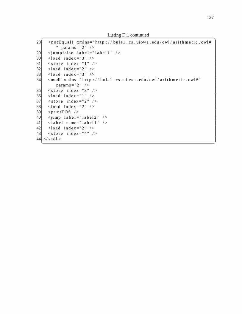
137
Listing D.1 continued✞ ☎28 < no t E qua l I xmlns=" h t t p : / / bu la1 . cs . uiowa . edu / owl / a ri t h m e t i c . owl#
" params =" 2 " / >29 < j um p f a l s e l a b e l =" l a b e l 1 " / >30 < load index =" 3 " / >31 < s t o r e index =" 1 " / >32 < load index =" 2 " / >33 < load index =" 3 " / >34 <modI xmlns =" h t t p : / / bu la1 . cs . uiowa . edu / owl / a r i t h m et i c . owl# "
params =" 2 " / >35 < s t o r e index =" 3 " / >36 < load index =" 1 " / >37 < s t o r e index =" 2 " / >38 < load index =" 2 " / >39 <pr intTOS / >40 <jump l a b e l =" l a b e l 2 " / >41 < l a b e l name=" l a b e l 1 " / >42 < load index =" 2 " / >43 < s t o r e index =" 4 " / >44 </ sad l >✝ ✆

138
REFERENCES
Agarwal, V., Dasgupta, K., Karnik, N., Kumar, A., Kundu, A.,Mittal, S. & Srivastava,B. (2005), A service creation environment based on end to endcomposition of webservices,in ‘Proceedings of the 14th international conference on WorldWide Web’,WWW ’05, ACM, New York, NY, USA, pp. 128–137.URL: http://doi.acm.org/10.1145/1060745.1060768
Aho, A. V., Sethi, R. & Ullman, J. D. (1986),Compilers: Principles, Techniques, andTools, Addison Wesley.
Altintas, I., Berkley, C., Jaeger, E., Jones, M., Ludascher, B. & Mock, S. (2004), Kepler: Anextensible system for design and execution of scientific workflows, in ‘IN SSDBM’,pp. 21–23.
Andrews, T. & et al. (2003), ‘Business process execution language for web services’.URL: https://www.oasis-open.org/committees/download.php/2046/BPEL%20V1-1%20May%205%202003%20Final.pdf
Baader, F., Horrocks, I. & Sattler, U. (2007), Chapter 3: Description Logics, in F. vanHarmelen, V. Lifschitz & B. Porter, eds, ‘Handbook of Knowledge Representation’,Elsevier.
Backus, J. W. (1959), The syntax and semantics of the proposed international algebraiclanguage of the zurich acm-gamm conference,in ‘IFIP Congress’, pp. 125–131.
Biermann, A. W. & Ballard, B. W. (1980), ‘Toward natural language computation’,Com-put. Linguist.6, 71–86.URL: http://portal.acm.org/citation.cfm?id=972439.972440
Bischof, M., Kopp, O., van Lessen, T. & Leymann, F. (2009), BPELscript: A SimplifiedScript Syntax for WS-BPEL 2.0,in ‘2009 35th Euromicro Conference on SoftwareEngineering and Advanced Applications (SEAA 2009)’, IEEE Computer SocietyPress, pp. 39–46.URL: http://www2.informatik.uni-stuttgart.de/cgi-bin/NCSTRL/NCSTRL_view.pl?id=INPROC-2009-49&engl=0
Boisvert, A., Arkin, A. & Riou, M. (2008), ‘Bpel simplified syntax’.URL: https://cwiki.apache.org/ODExSITE/bpel-simplified-syntax-simbpel.html
Box, D., Ehnebuske, D., Kakivaya, G., Layman, A., Mendelsohn, N., Nielsen, H. F., Thatte,

139
S. & Winer, D. (2000), ‘Simple Object Access Protocol (SOAP)1.1’.URL: http://www.w3.org/TR/soap/
Christensen, E., Curbera, F., Meredith, G. & Weerawarana, S. (2001), ‘Web Services De-scription Language (WSDL) 1.1’.URL: http://www.w3.org/TR/wsdl.html
Cickovski, T. M. (2004), Biologo, a domain-specific language for morphogenesis, Master’sthesis, Computer Science and Engineering, University of Notre Dame.
Clement, L., Hately, A., von Riegen, C. & Rogers, T. (2004), ‘Uddi version 3.0.2 spec’.URL: http://uddi.org/pubs/uddi_v3.htm
Craig, I. D. (2006),Virtual machines, Springer-Verlag.
Curcin, V. & Ghanem, M. (2008), Scientific workflow systems - can one size fit all?,in ‘Biomedical Engineering Conference, 2008. CIBEC 2008. Cairo International’,pp. 1–9.
Curtis, D. E., Rus, T. & Jensen, J. (2008), Application driven software for chemistry,in‘2008 IEEE International Conference on Electro/Information Technology, EIT 2008,held at Iowa State University, Ames, Iowa, USA, May 18-20, 2008’, IEEE, pp. 361–366.
Deelman, E., Singh, G., hui Su, M., Blythe, J., Gil, Y., Kesselman, C., Mehta, G., Vahi,K., Berriman, G. B., Good, J., Laity, A., Jacob, J. C. & Katz, D. S. (2005), ‘Pegasus:a framework for mapping complex scientific workflows onto distributed systems’,SCIENTIFIC PROGRAMMING JOURNAL13, 219–237.
Deursen, A. V., Klint, P. & Visser, J. (2000), ‘Domain-specific languages: An annotatedbibliography’,ACM SIGPLAN NOTICES35, 26–36.
DeVito, Z., Joubert, N., Palacios, F., Oakley, S., Medina, M., Barrientos, M., Elsen, E.,Ham, F., Aiken, A., Duraisamy, K., Darve, E., Alonso, J. & Hanrahan, P. (2011),Liszt: a domain specific language for building portable mesh-based pde solvers,in‘Proceedings of 2011 International Conference for High Performance Computing,Networking, Storage and Analysis’, SC ’11, ACM, New York, NY, USA, pp. 9:1–9:12.URL: http://doi.acm.org/10.1145/2063384.2063396
DuCharme, B. (2011),Learning SPARQL, O’Reilly Media.
Erl, T., Balasubramanian, R., Carlyle, B. & Pautasso, C. (2012), SOA with REST: Princi-

140
ples, Patterns and Constraints for Building Enterprise Solutions with REST, PrenticeHall.
Fischer, C. N., Cytron, R. K. & LeBlanc, R. J. (2010),Crafting a Compiler, Addison-Wesley.
Gamma, E., Helm, R., Johnson, R. & Vlissides, J. (1995),Design patterns: elements ofreusable object-oriented software, Addison-Wesley Longman Publishing Co., Inc.,Boston, MA, USA.
Gasevic, D., Djuric, D. & Devedzic, V. (2009),Model Driven Engineering and OntologyDevelopment, 2nd edn, Springer Publishing Company, Incorporated.
Green, T. & Petre, M. (1992), When visual programs are harderto read than textual pro-grams,in ‘Sixth European Conference on Cognitive Ergonomics’, pp. 167–180.
Gubala, T., Bubak, M., Malawski, M. & Rycerz, K. (2006), Semantic-based grid work-flow composition,in ‘Proceedings of the 6th international conference on Parallel Pro-cessing and Applied Mathematics’, PPAM’05, Springer-Verlag, Berlin, Heidelberg,pp. 651–658.URL: http://dx.doi.org/10.1007/11752578_78
Horn, P. (2001), AUTONOMIC COMPUTING: IBM’s Perspective onthe State of Infor-mation, Technical report, IBM Corporation.
Kiper, J. D., Auernheimer, B. & Ames, C. K. (1997), ‘Visual depiction of decision state-ments: What is best forprogrammers and non-programmers?’,Empirical Softw. Engg.2(4), 361–379.URL: http://dx.doi.org/10.1023/A:1009797801907
Knöll, R. & Mezini, M. (2006), Pegasus: first steps toward a naturalistic programminglanguage,in ‘Companion to the 21st ACM SIGPLAN symposium on Object-orientedprogramming systems, languages, and applications’, OOPSLA ’06, ACM, New York,NY, USA, pp. 542–559.URL: http://doi.acm.org/10.1145/1176617.1176628
Knuth, D. E. (1965), ‘On the translation of languages from left to right’, Information andControl8(6), 607 – 639.
Krishnan, S. & Bhatia, K. (2007), Soas for scientific applications: Experiences andchallenges,in ‘e-Science and Grid Computing, IEEE International Conference on’,pp. 160–169.

141
Liu, H. & Lieberman, H. (2005a), Metafor: visualizing stories as code,in ‘Proceedings ofthe 10th international conference on Intelligent user interfaces’, IUI ’05, ACM, NewYork, NY, USA, pp. 305–307.URL: http://doi.acm.org/10.1145/1040830.1040908
Liu, H. & Lieberman, H. (2005b), Programmatic semantics for natural language interfaces,in ‘CHI ’05 extended abstracts on Human factors in computing systems’, CHI ’05,ACM, New York, NY, USA, pp. 1597–1600.URL: http://doi.acm.org/10.1145/1056808.1056975
Lopes, C. V., Dourish, P., Lorenz, D. H. & Lieberherr, K. (2003), ‘Beyond AOP: TowardNaturalistic Programming’,ACM SIGPLAN Notices38(12), 34–43. OOPSLA’03Special Track on Onward! Seeking New Paradigms & New Thinking.URL: http://www.ccs.neu.edu/home/lorenz/papers/oopsla03a/
Margolis, B. (2007),SOA for the Business Developer: Concepts, BPEL, and SCA, McPress.
Martin, D. & et al (2003), ‘Daml-s (and owl-s) 0.9 draft release’.URL: http://www.daml.org/services/daml-s/0.9/
McCarthy, J. (1980), ‘Circumscription - a form of non-monotonic reasoning’,ArtificialIntelligence13(1-2), 27 – 39. Special Issue on Non-Monotonic Logic.URL: http://www.sciencedirect.com/science/article/pii/0004370280900119
McDermott, D. V. (2002), Estimated-regression planning for interactions with web ser-vices,in M. Ghallab, J. Hertzberg & P. Traverso, eds, ‘AIPS’, AAAI, pp. 204–211.
McGuinness, D. L. & van Harmelen, F. (2004), ‘OWL Web Ontology Language’.URL: http://www.w3.org/TR/owl-features/
McIlraith, S. A. & Son, T. C. (2002), Adapting golog for composition of semantic webservices,in D. Fensel, F. Giunchiglia, D. L. McGuinness & M.-A. Williams, eds,‘KR’, Morgan Kaufmann, pp. 482–496.
Mernik, M., Heering, J. & Sloane, A. M. (2005), ‘When and how to develop domain-specific languages’,ACM Comput. Surv.37(4), 316–344.URL: http://doi.acm.org/10.1145/1118890.1118892
Miller, L. A. (1981), ‘Natural language programming: Styles, strategies, and contrasts’,IBM Systems Journal211(2), 184–215.

142
Mordani, R. (2009), Jsr 315: Javatm servlet 3.0 specification, Technical report, OracleCorporation.URL: http://www.jcp.org/en/jsr/detail?id=315
Myers, B. A., Pane, J. F. & Ko, A. (2004), ‘Natural programming languages and environ-ments’,Commun. ACM47, 47–52.URL: http://doi.acm.org/10.1145/1015864.1015888
Narayanan, S. & McIlraith, S. A. (2002), Simulation, verification and automated compo-sition of web services,in ‘Proceedings of the 11th international conference on WorldWide Web’, WWW ’02, ACM, New York, NY, USA, pp. 77–88.URL: http://doi.acm.org/10.1145/511446.511457
Oinn, T., Addis, M., Ferris, J., Marvin, D., Carver, T., Pocock, M. R. & Wipat, A. (2004),‘Taverna: A tool for the composition and enactment of bioinformatics workflows’,Bioinformatics20, 2004.
Petre, M. (1995), ‘Why looking isn’t always seeing: readership skills and graphical pro-gramming’,Commun. ACM38(6), 33–44.URL: http://doi.acm.org/10.1145/203241.203251
Polya, G. (1945),How to Solve It, Princeton University Press.
Popek, G. J. & Goldberg, R. P. (1974), ‘Formal requirements for virtualizable third gener-ation architectures’,Commun. ACM17(7), 412–421.URL: http://doi.acm.org/10.1145/361011.361073
Price, D., Rilofff, E., Zachary, J. & Harvey, B. (2000), NaturalJava: a natural languageinterface for programming in Java,in ‘Proceedings of the 5th international conferenceon Intelligent user interfaces’, IUI ’00, ACM, New York, NY,USA, pp. 207–211.URL: http://doi.acm.org/10.1145/325737.325845
Qin, J. & Fahringer, T. (2008), A novel domain oriented approach for scientific grid work-flow composition,in ‘Proceedings of the 2008 ACM/IEEE conference on Supercom-puting’, SC ’08, IEEE Press, Piscataway, NJ, USA, pp. 21:1–21:12.URL: http://dl.acm.org/citation.cfm?id=1413370.1413392
Rao, J. & Su, X. (2004), A survey of automated web service composition methods,in ‘InProceedings of the First International Workshop on Semantic Web Services and WebProcess Composition, SWSWPC 2004’, pp. 43–54.
Ross, D. T. (1978), ‘Origins of the apt language for automatically programmed tools’,SIGPLAN Not.13(8), 61–99.URL: http://doi.acm.org/10.1145/960118.808374

143
Rus, T. (1993),System Software and Software Systems: Systems Methodologyfor SystemSoftware, Vol. 1, World Scientific Pub Co Inc.
Rus, T. (2008), Liberate computer user from programming,in J. Meseguer & G. Rosu,eds, ‘Algebraic Methodology and Software Technology, 12thInternational Confer-ence, AMAST 2008, Urbana, IL, USA, July 28-31, 2008, Proceedings’, Vol. 5140 ofLecture Notes in Computer Science, Springer, pp. 16–35.
Rus, T. (2013), Computer integration within problem solving process,in ‘Proceedings ofRoEduNet 11th International Conference: Networking in Education and Research’,Sinaia, Romania.
Rus, T. & Bui, C. (2010), Software development for non-expert computer users,in ‘Pro-ceedings of the International Conference on Cloud Computing and Virtualization’,CCCV ’2010, Singapore.
Rus, T. & Curtis, D. E. (2006), Application driven software development,in ‘Proceedingsof the International Conference on Software Engineering Advances (ICSEA 2006),October 28 - November 2, 2006, Papeete, Tahiti, French Polynesia’, IEEE ComputerSociety.
Rus, T. & Curtis, D. E. (2007), Toward application driven software technology,in H. R.Arabnia & H. Reza, eds, ‘Proceedings of the 2007 International Conference on Soft-ware Engineering Research & Practice, SERP 2007, Volume I, June 25-28, 2007, LasVegas Nevada, USA’, CSREA Press, pp. 282–288.
Sammet, J. E. (1966), ‘The use of english as a programming language’,Commun. ACM9, 228–230.URL: http://doi.acm.org/10.1145/365230.365274
Scanlan, D. A. (1989), ‘Structured flowcharts outperform pseudocode: An experimentalcomparison’,IEEE Softw.6(5), 28–36.URL: http://dx.doi.org/10.1109/52.35587
Sipser, M. (2006),Introduction to Theory of Computation, Cengage.
Srivastava, B. & Koehler, J. (2003), Web service composition - current solutions and openproblems,in ‘In: ICAPS 2003 Workshop on Planning for Web Services’, pp. 28–35.
Taylor, I. J., Wang, I., Shields, M. S. & Majithia, S. (2005),‘Distributed computing withtriana on the grid’,Concurrency - Practice and Experience17(9), 1197–1214.
Welty, C. & Guarino, N. (2001), ‘Supporting ontological analysis of taxonomic relation-

144
ships’,Data and Knowledge Engineering39(1), 51 – 74. 19th International Confer-ence on Conceptual Modeling (ER2000).
Wolfram, S. (2010), ‘Programming with natural language is actually going to work’.URL: http://blog.wolfram.com/2010/11/16/programming-with-natural-language-is-actually-going-to-work/
Woods, W. A. (1970), ‘Transition network grammars for natural language analysis’,Com-mun. ACM13, 591–606.URL: http://doi.acm.org/10.1145/355598.362773