การประเมินประสิทธิภาพสิ่งแวดล้อมทางการเรียนรู้ Evaluation learning environment
Upload
phungquynhCategory
view
217download
0
An Evaluation of Software Test Environment Architectures
Nancy S. Eickehnann and Debra J. Richardson
Information and Computer Science Department
University Of California Irvine
Irvine, California 92715 USA
[email protected] and [email protected]
AbstractSo~are Test Environments (STES) provide a means of
automating the test process and integrating testing tools to
support required testing capabilities across the test pro-cess. Specifically, STES may support test planning, testmanagement, test measurement, test failure analysis, test
development, and test execution. The software architectureof an STE describes the allocation of the environment’sjimctions to spec.i$c implementation structures. An STE’Sarchitecture can facilitate or impede modifications such aschanges to processing algorithms, data representation, orjimctionality. Perjorrnance and reusability are also subjectto architecturally imposed constraints. Evaluation of anSTE’S architecture can provide insight into modifiability,extensibility, portability and reusability of the STE. Thispaper proposes a reference architecture for STES. Its ana-lytical value is demonstrated by using SAAM (So@areArchitectural Anulysis Method) to compare three sojlwaretest environments: PROTest II (Prolog Test Environment,Version II), TAOS (Testing with Analysis and Oracle Sup-port), and CITE (CONVEX Integrated Test Environment).
1 Introduction
Software testing is a critical activity in the development
of high quality software. When testing is performed manu-
ally it is highly error-prone, time consuming and costly.
Software Testing Environments (STES) overeome the defi-
ciencies of manual testing through automating the test pro-
cess and integrating testing tools to support a wide range
of test capabilities. Industrial use of STES provide signifi-
cant benefits by reducing testing costs, improving test
accuracy, improving software quality, and providing for
test reproducibility [17, 20].
Despite the critical importance of S333s in the develop-
ment of quality software, rigorous evaluation of their
capabilities has keen largely ignored. Comparisons are fre-
quently made among STES using a taxonomic approach
[6, 12, 14,5, 18]. These illustrate whether a system sup-
ports a given task or has a specific attribute.
How well an STE meets its intended goals is usually
drawn from textual descriptions. A uniform graphical
depiction complements textual descriptions, thereby facili-
tating evaluation of developers claims concerning qualities
of STlk Examples of typical claims are
The rule-based approach offers many advantagesover more traditional test execution systems...whichrequire that each test case carry with it a script or aprogram to perform the necessary executions andresults verification [20].
Developing sophisticated testing capabilities through
composition of less complex, more general compo-nents proved to be an extremely effective approach, itfacilitates rapid prototyping and lower development
costs for new tools as well as tool integration [17].
It has been demonstrated that some system qualities can
be evaluated through an analysis of the system’s software
architecture, where an architecture consists of both system
structure and functionality. A uniform graphical depiction
of system architectures facilitates such an analysis [8,10].
The Software Architecture Analysis Method (SAAM)
provides an established method for describing and analyz-
ing software architectures [10]. SAAM is used in this
paper to examine three STF!S: PROTest II (Prolog Test
Environment Version II), TAOS (Testing with halysis
and Oracle Support), and CITE (CONVEX Integrated Test
Environment). The terminology used to describe SW
in this paper is consistent with that of [10], where SAAM
is defined as consisting of the following steps:
1. Characterize a canonical functional partition for
the domain.
2. Create a graphical diagram of each system’s struc-
ture using the SAAM graphical notation.
3. Allocate the functional partition onto each sys-
tem’s structural decomposition.
4. Choose a set of quality attibutes with which to
assess the architectures.
5. Choose a set of concrete tasks which test the
desired quality attributes.
6. Evaluate the degree to which each architecture pro-
vides support for each task, thus indicating satisfac-
tion of the desired quality.
0270-5257/96 $5.0001996 IEEE 353Proceedings of ICSE-18

To accomplish this analysis, the SAAM method takes
three perspectives: a canonical functional partition of the
domain, system structure, and allocation of functionality
to system structm.
The tit perspective, a canonical functional partition of
the application domain, may be provided by a reference
architecture. If one is not available, a domain analysis can
be done to determine the necessary partitioning of func-
tionality.
In this paper, the three STEs are presented as originally
published and then their system stmctum is recast in the
SAAM architectural notation. Using a uniform notation
permits a common level of understanding on which to base
the analysis.
For each STE, the canonical functional partition is then
allocated to its structural decomposition. The architecture
can then be evaluated with respect to specific quality
attributes. To ascertain if a system has a particular quality,
concrete tasks are chosen to demonstrate the presence or
absence of that quality in the STE. The analysis deter-
mines whether the architecture supporta specific tasks or
not in accordance with the qualities attributable to the sys-
tem.
1.1 Overview
In section 2, the three architecturalanalysis perspectives
used by SAAM am described. The canonical functional
partition is a result of a domain analysis of the test process
and test process automation. This results in a reference
architecture for STES. Them the graphical notation that is
used by SAAM to describe system structure is provided.
Finally, the allocation of functionality to system structure
is described. This section sets the groundwork for evaluat-
ing the architecture of STES.
Section 3 describes each of the three STES to be evalu-
ated PROTest II, TAOS, and CITE. Each is first described
as originally diagramed and discussed by the authors and
then nxast in the graphical notation used by SAAM along
with an allocation of the canonical functional partition.
Section 4 delhes the quality of reusability of test arti-
facts analyzed in this paper. The test artifacts and the func-
tional partition to which they are relevant are deactibed.
Each of the three STES is then evaluated with respect to
test artifact reusability.
Section 5 concludes with a summary of results and con-tributions as well as a discussion of future work.
Specific contributions of the paper include an initial ref-
erence amhitectum for So&vare Test Environments
(STEs), a comparison of three WE-s using the SoftwareArchitectural Analysis Meth@ an evaluation of architec-
tural constraints on test artifact reusability, and further
evaluation of SAAM as an analysis method for software
architectures.
2 Architectural Analysis Perspectives
Using SAAM, architectural analysis is approached from
three perspectives: a canonical functional partition, system
stmcture, and allocation of functionality to system struc-
ture. This section describes these three perspectives.
2.1 Canonical Functional Partition
A canonical functional partition of the application
domain provides tbe functional perspective required by
SAAM. Reference architectures, such as the Arch/Slinky
Mets-model for UIMSS (User Jnterface Management Sys-
tems) and the Toaster model for SDES (Software Develop-
ment Environments), provide fictional characterizations
for their domains. In mature domains such as these, a
canonical functional partition has been accomplished
through extensive domain analysis by researchers in the
field.
Software Test Euvironmenta do not yet have a reference
architecture to characterize their domain specific function-
ality. A domain analysis is needed to accomplish this. The
domain analysis and resulting canonical functional parti-
tion for STE5 requires that two aspects be evaluated the
specific testing activities inclusive in an ideal test process
[9] and the functions specific to the automation of that pro-
cess.
STEa pose a significant challenge for domain analysis.
This is in part due to the rapid advances in test technology
as well as the evolution of the test process that should be
automated by an STE. Gelperin and Hetzel point out that
over the years the test process has increased in scope
across the life cycle and has been refocused as to ita pri-
mary goals and objectives [9]. STH.Shave not all kept up
with the state-of-the-art in test process or its automation.
To describe the STE’S process focus, we provide a history
of test process evolution.
Test process evolution is shown in figure 1. The test
process began with a debugging focus in the early 50’s,
where the process took an ad hoc approach of simply find-
ing bugs. The test process then evolved to a demonstration
period, which focused on making sure the program ran andsolved the intended problem. This period was followed by
the destruction period, which focused on executing a pro-
gram to tid failures through implementation-based test-
ing. Next, an evaluation-oriented period addressed the
integration of methods to provide evaluative support
throughout the software lifecycle, as described in the Fed-
eral Information Processing Systems (FIRS) guidelines
[13]. The evaluation process focuses on detecting require
354

ments, design, and implementation faults, which requires
an early life cycle testing effort. The current test process is
a life cycle prevention model, which focuses on fault pre-
vention through parallel development and test processes.
The change of emphasis has been from detection of faults
to one of prevention of faults.
1950-1956 The Debugging-Oriented Period1957-1978 The Demonstration-Oriented Period1979-1982 The Destruction-Oriented Period1983-1987 The Evaluation-Oriented Period1988-1995 The Prevention-Oriented Period
Figure 1. Test process evolution, adapted from [9]
Our domain analysis evaluated the software test pro-
cess, test process automation, and current ST&. The anal-
ysis resulted in a partitioning of the STE domain into six
canonical functions: test execution, test development, test
failure analysis, test measurement, test msnagemen~ and
test planning.
● Test Execution includes the execution of the instru-
mented source code and recording of execution
traces. Test artifacts ntcorded include test output
resuha, test execution traces, and test status.
● Test Development includes the specification and
implementation of a test cotiguration. This results in
a test suite, the input related test artifacts, and docu-
mentation. Specific artifacts developed include test
oracles, test cases, and test adequacy criteria.
● Test Failure Analysis includes behavior verification
and documentation and analysis of test execution
pass/fail statistics. Specific artifacts include pass/fail
state and test failure reports.
● Test Measurement includes test coverage measure-
ment and analysis. Source code is typically instru-
mented to collect execution traces. Resulting test
artifacts include test coverage measures and test fail-
ure measures.
● Test Management includes support for test artifact
persistence, artifact relations persistence, and test
execution state preservation. Test process automation
requires a repository for test artifacts. A passive
repository such as a file serves the basic need of stor-
age. However, an active repository is needed to sup-
port relations among test artifacts and provide fortheir persistence.
● Test PZanning includes the development of a master
test plan, the features of the system to be tested, and
detailed test plans. Included in this function are risk
assessment issues, organizational training needs,required and available resources, comprehensive test
strategy, resource and staffing requirements, roles and
responsibility allocations, and overall schedule.
/
canonical TestFunctional ProcessPartitions Evolutiou
Debugging........................ ......................
Demonstration
....................................
Destruction
Test
\
...........................
Measurement Evaluation
TestManagement
— .................Prevention
TestPlaoning
\/ ~----------Figure 2. STEP Model
The test process evolution and canonical functional par-
tition resulting f%om the STE domain analysis provide the
foundation for the Software Test Environment Pyramid
(STEP) model. The STEP model, shown in figure 2, strati-
fies test functionalities from the apex of the pyramid to its
base in a corresponding progression of test process evolu-
tion as described in figure 1. Each period represented in
the pyramid includes the functionalities of previous peri-
ods as you descend from the apex to the base.
The top section of the pyramid represents the function
of test execution. Test execution is clearly required by any
test process. The test process focus of the debugging-ori-
ented period was solely on test execution.
The second segment of the pyramid, from the top, is
divided into two scalene triangles. The smaller scalene tri-
angle representa test development. The larger scalene tri-
angle represents test failure analysis. The relative
positions and sizes have semantic significance.Test development played a more significant role to the
overall test process during the demonstration-oriented and
destruction-oriented periods due to the manual intensive
nature of test development at that time. Test development
methods have not significantly changed, although theyhave improved in reliability and reproducibfity with auto-
mation. Thus, their role in test process has diminished in
significance as you move ahead in test procxws evolution.
355
Test failure analysis was less important when performed
manually, as interactive checking by humans added little
benefit for test behavior verification. The methods applied
to test failure analysis have increased in their level of
sophistication, making test failure analysis more signifi-
cant to the overall test process. One of the most significant
advances are specification-based test oracles which
enables early entry of the test process into the life cycle.
This is a key difference in test process focus as it
progresses towards the prevention-oriented period.
Test measurement is represented by the third segment in
the pyramid. Test measurement is required to support the
evaluation-oriented period, which represents the point of
departure from a phase approach to a life cycle approach,
A significant change in the test process focus is that testing
is applied in parallel to development not merely at the end
of development. Test measurement also enables evaluating
and improving the test process.
Approaching the base of the pyramid, the fourth seg-
ment representa test managemen~ which is essential to the
evaluative test process due to the sheer volume of informa-
tion that is created and must be stored, retrieved, and
reused. Test management is critical for test process repro-
ducibility.
The base, or foundation, of the pyramid is test planning.
Test planning is the essential component of the prevention-
oriented period, Test planning introduces the test process
before requirements, so that rather than being an after-
thought, testing is preplanned and occurs concurrently
with development.
The Software Test Environment Pyramid reference
architecture presented here is an initial attempt at a dia-
grammatic representation of the canonical functional parti-
tion of the Software Test Environment domain. We will
continue to refine and improve the STEP model and wel-
come other researchers to do the same. To avoid overuse
of the term architecture, canonical functional partition is
used in the remainder of the paper in deference to refer-ence architecture.
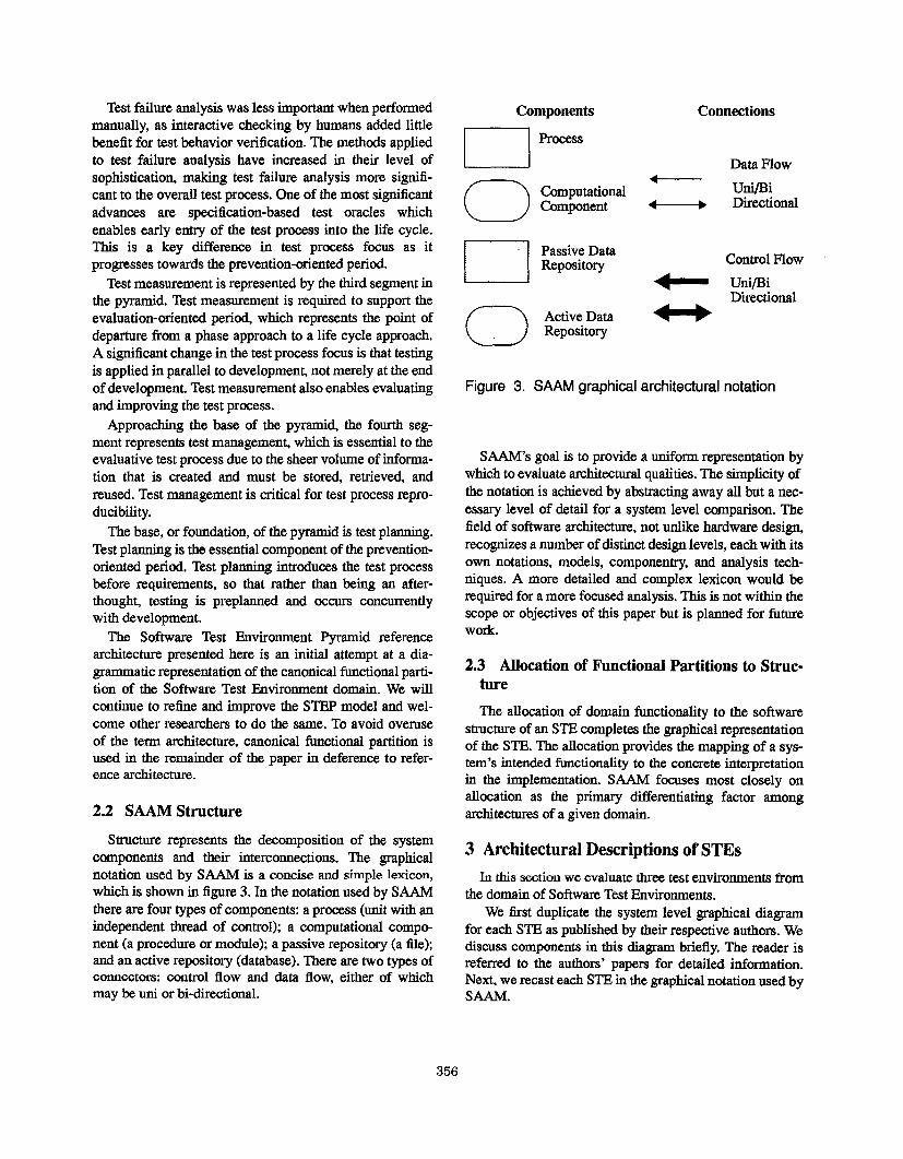
2.2 SAAM Structure
Structure represents the decomposition of the system
components and their interconnections. The graphical
notation used by SAAM is a concise snd simple lexicon,
which is shown in figure 3. In the notation used by SAAM
there are four types of components: a process (unit with an
independent thread of control); a computational compo-
nent (a procedure or module); a passive repository (a file);
and an active repository (database). There are two types ofconnectom: control flow and data flow, either of which
may be uni or hi-directional.
Components
I
o ComputationalComponent
[ I Passive DataRepository
(3 Active DataRepository
Connections
Data Flow4
Uni/Bi4 ➤ Directional
Control Flow
+ Uni/BiDirectional
Figure 3. SAAM graphical architectural notation
SAAM’S goal is to provide a uniform representation by
which to evaluate architectural qualities. The simplicity of
the notation is achieved by abstracting away all but a nec-
essary level of detail for a system level comparison. The
field of software architecture, not unlike hardware design,
recognizes a number of distinct design levels, each with its
own notations, models, componentry, and analysis tech-
niques. A more detailed and complex lexicon would be
required for a more focused analysis. This is not within the
scope or objectives of this paper but is planned for future
work.
2.3 Allocation of Functional Partitions to Struc-ture
The allocation of domain functionality to the software
structure of an STE completes the graphical representation
of the STE. The allocation provides the mapping of a sys-
tem’s intended functionality to the concrete interpretation
in the implementation. SAAM focuses most closely on
allocation as the primary differentiating factor among
architectures of a given domain.
3 Architectural Descriptions of STES
In this section we evaluate three test environments from
the domain of Software Test Environments.
We &-at duplicate the system level graphical diagram
for each STE as published by their respective authors. We
discuss components in this diagram briefly. The reader is
referred to the authors’ papem for detailed information.
Next, we recast each STE in the graphical notation osed by
SAAM.
356
PDLT/1Program
structureChecker
Teat
v
TeatReportGenerator
\uReport
(1TestRept
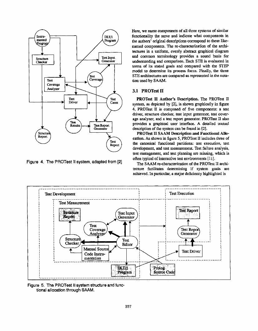
Figure 4. The PROTest II system, adapted from [2]
Here, we name components of all three systems of stillar
functionrdity the same and indicate what components in
the authora’ original descriptions correspond to these like-
narned components. The re-characterization of the archi-
tectures in a uniform, evenly abstract graphical diagram
and common terminology provides a sound basis for
understanding and comparison. Each STE is evaluated in
terms of ita stated goals and compared with the STEPmodel to determine its process focus. Finally, the three
STE architectures are compared as represented in the nota-
tion used by SAAM.
3.1 PROTest II
PROTest 11 Author’s Description. The PROTest II
system, as depicted by [2], is shown graphically in figure
4. PROTest II is composed of five components: a test
driver, structure checker, test input generator, test cover-
age analyzer, and a test report generator. PROTest II alsoprovides a graphical user interface. A detailed textual
description of the system can be found in [2].
PROTest II SAAM Description and Functional Allo-
cation. As shown in figure 5, PROTeat 11includes three of
the canonical functional partitions test execution, test
development, and test measurement. Test failure analysis,
test managemen~ and test planning are missing, which is
often typical of interactive test environments [11].
The”SAAM re-characterization of the PROTest 11archi-
tecture facilitates determining g if system goals are
achieved. In particular, a major deficiency highlighted is
------------------- ------ ------ ------------------------- ;-------------------------------, #~ Test Development
,\ Test Execution
It
s, I , #
,,,,
,,0$,
,
0,
,,
,,
,
,------ ---------------------------------- ------- 4 -------------- + ---------------------
~ Test MeasurementI1t
II
I
h
I
t
tb
I8
II
oII--
,
l -----------------------------------------------------------
,-------------------------------------------------------- .
---, 1#I
, 1
I tI
I I
( I,
6 t# o1
,, rt
,1 I
t 1
I I1 It 14 I
------,t
---------- J
Figure 5. The PROTest II system structure and func-tional allocation through SAAM.
357
I TAOSI1I
.--.,; .:. -
----- ,.. ; =-----
Teat Developmen~------------- ,.--”’-: ..::. .+-
m& &’y&----M:me”t
Teat Management
S’=.+
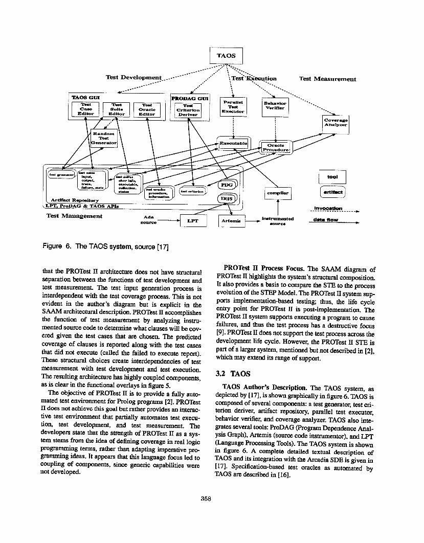
Figure 6. The TAOS system, source[171
that the PROTest II architecture does not have structural
separation between the functions of test development and
test measurement. The test input generation process is
interdependent with the test coverage process. This is not
evident in the author’s diagram but is explicit in theSAAM architectural description. PROTest II accomplishes
the function of test measurement by analyzing instru-
mented source code to determine what clauses will be cov-
ered given the test cases that are chosen. The predicted
coverage of clauses is reported along with the test cases
that did not execute (called the failed to execute report).These structural choices create interdependencies of test
measurement with test development and test execution.
The resulting srchitectme has highly coupled components,
as is clear in the functional overlays in figure 5,
The objective of PROTest II is to provide a fully auto-
mated test environment for Prolog programs [2]. PROTestII does not achieve this goal but rather provides an interac-
tive test environment that partially automates test execu-
tiou test development, and test measurement. The
developers state that the strength of PROTest II as a sys-
tem stems from the idea of delining coverage in real logic
programming terms, rather than adapting imperative pro-
@amming ideas. It appears that this language focus led tocoupling of components, since generic capabilities were
not developed,
. . . . .*
PROTest II Process Focus. The SAAM diagram of
PROTest II highlights the system’s structural composition.
It also provides a basis to compare the STE to the process
evolution of the STEP Model. The PROTest II system sup-
ports implementation-based testing thus, the life cycle
entry point for PROTest II is post-implementation. The
PROTest II system supports executing a program to cause
failures, and thus the test process has a destructive focus
[9]. PROTest II does not support the test process across the
development life cycle. However, the PROTest II STE is
part of a larger system, mentioned but not described in [2],
which may extend its range of support.
3.2 TAOS
TAOS Author’s Description. The TAOS system as
depicted by [17], is shown graphically in figure 6. TAOS is
composed of several components: a test generator, test cri-terion deriver, artifact repository, parallel test executor,
behavior verifier, and coverage analyzer. TAOS also inte-
grates several tools ProDAG (Program Dependenm Anal-
ysis Graph), Artemis (source code instmmentor), and LPT
@@age processing Tools). The TAOS system is shownin figure 6. A complete detailed textual description of
TAOS and its integration with the Arcadia SDE is given in
[17]. Specification-based test oracles as automated by
TAOS are described in [16].
358
--------------------- . r ------------- --------1 , ----------------- ---------------- ---------- *
\ Test Development ~
1 I ,
I
------------------- ,1,
ProDAG 4I\
‘;:;:’; :.:~&:**,;T::;:?;:’’:’; ;:f::j:;’,,
~ml ( “’’” ) ‘g !
,,:,, *:”, :-&*M;;,,;;::::[~’::;;,
$w+’:”:’::::i .------:::::::-:::'_;:: -:-:: -_-------:::------------------------------
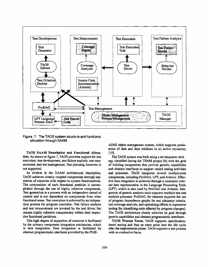
Figure 7. The TAOS system structure and functionalallocation through SAAM
ADES objeet management system, which supporta persis-
tence of data and data relations in an active reuositorvTAOS SAAM Description and Functional Alloca-
tion. As shown in figure 7, TAOS provides support for test
execution, test development, test failure analysis, test mea-
surement, and test management. Test planning, however, is
not supported.
As evident in the SAAM architectural description,
TAOS achieves loosely cnupled components through sep-
aration of concerns with respect to system functionalities.
The composition of each functional partition is accom-
plished through the use of highly cohesive components.
Test generation is a process with an independent thread of
control and is not dependent on components from other
functional areas. Test execution is achieved by an indepen-
dent process for program execution. Test failure analysis
and test measurement are invoked by the test driver, but
remain highly cohesive componentry within their respec-
tive functional partitions.
This high degree of separation of concerns is facilitated
by the primary component integration mechanism, whichis data integration. Data integration is facilitated by
abstract programmatic interfaces provided by the PLEI-
[19].
The TAOS system was built using a development strat-
egy identified during the TEAM project [4] with the goal
of building components that provide generic capabilities
and abstract interfaces to support varied testing activities
and processes. TAOS integrates several multipurpose
components, including ProDAG, LPT, and Artemis. Effec-
tive data integration is achieved through a consistent inter-
nal data representation in the Language Processing Tools
(LPT), which is also used by ProDAG and ,Artemis. Inte-gration of generic analysis tools supports multiple test and
analysis purposes. ProDAG, for instance supports the use
of program dependence graphs for test adequacy criteria,
test coverage analysis, and optimizing efforts in regression
testing (by identifying code affeeted by program changes).
The TAOS arehiteetare clearly achieves its goal through
genetic capabilities and abstract programmatic interfaces,
TAOS Process Focus. TAOS supports specification-
bssed testing and thus an entry point into the life cycleafter the requirements phase. TAOS suppoms a test process
with an evaluative focus.
359

sourceConml Test Coverage Anslysis.---z”--- -z--z-,I
,- .-=---- --------- --------- --------- --------- -------,#
H-H
.------
D,--?- ~-------=-J~~--------=--------------------------------................................
! I I TC
‘w=*
xp. Files i
1#I
Figure 8. The CITE system, adapted from [20]
3.3 CITE mated, general purpose software. test environment.- .- _———
CITE Author’s Description. The CITE system, as
depicted by [20], is shown graphically in figure 8 (only the
components of CITE developed by Convex are shown).
The CITE architecture consists of several components: a
test driver (’ID), test coverage analyzer (TCA), test data
reviewer (TDReview and TDPP), test generator, and data-
bases and a rule base. Additional tools have been inte-
grated for use with the system. Specifically, the OCT test
coverage tool expanda the typea of test coverage measuredby the environment and the EXPECT simulator provides
for special purpose interactive testing. A complete textual
description of CITE is given in [20].
CITE SAAM Description and Functional Allocation.
The SAAM graphical depiction of CITE, as shown in fig-
ure 9, reflects the structural separation desired in a systemthat controls the test process automatically. CITE provides
support for test execution, test development test failure
analysis, test measurement, and test management. CITE
does not support teat planning,
CITE has achieved the desired functionalities throughallocation to atructarally cohesive components. The pro-cess control exercised by the ride-base ia evidenced in
direct control to each functional area. This clean separa-tion of concerns supports the primary goal of a fully auto-
CITE Proce-= Focus. CITE supports implementation-
baaed testing. CITE has a destructive test process focus
that is, it executes a program to &tect failures, which is a
limited scope for automation of the test process. However,
all testing functionalities supported by CITE are fully
automated,
3.4 STE Comparison
The three STEa share stated goals of automating the test
process. The use of SAAM clarifies how well each STE
achieves this goal and to what degree. SAAM uses a
canonical functional partition to characterize the system
structure at a component level. The functionalities sup-
ported and stmctural constraints imposed by the architec-
ture are more readily identified when compared in auniform notation.
Test process focus was identified for each STE. PRO-
Test II and CITE support implementation-baaed testiug
and have a destructive test process focus. This focus has a
limited scope of life cycle applicability, as it initiates test-ing after implementation for the purpose of detecting fail-
ures. TAOS supporta specification-baaed testing and has
an evaluative teat process focus. An evaluative test process
focus provides complete life cycle support, as failure de-
360

,Z------------- ,
, -------------- ,
- . ------------,, -------------- ,
: Test Test~ Measurement ~
Test Test,. :
~q ii 1$1 /jl
t # , I# 1 t1 1 ## t II I I II # I, ------------- I
,
H
!--------------I ,-------------.
N It
/----- -------!
,-------- !t---------------------------------------------------------------
I [1
.,, ,
~ ‘e’- m - “ ‘!:
k————— “’,:’C?A4’,:,,:’”
--------------------------------------------------------------------------------!
Figure 9. The CITE system structure and functionalallocation through SAAM
tection extends ffom requirements and design to code. Test
process focus appears to dictate the scope of automation
achieved across the life cycle and the types of functional-
ity supported by an STE.
Test planning is not supported by any of the three STES.
Test planning functionality specifically supports a preven-
tative test process focus. We could not Iind an STE that
explicitly supports a preventative process. Some tools
address planning as a separate issue but fail to integrate
test artifacta with a parallel development effort. A preven-
tative process focus may be best achieved through inte-
grating an STE with an SDE.
Test Management is not supported in PROTest II. CITE
and TAOS support test management with an active reposi-
tory. TAOS provides support for object management and
process management. CITE provides support for object
management, rule-based test process templates and config-
uration management. Test management is essential for full
automation. The test process spans a temporal boundary of
the life cycle and generates voluminous amounts of testartifacts with complex relations that must be supported by
test management. Coordinating the test process over time
is not possible without automated test management.
Test Measurement in PROTest II is tightly coupled with
test development and test execution. PROTest II only par-
tially automates measurement, specifically source code
instrumentation is done manually. PROTest II addresses
test measurement and test development by focusing on the
language constructs of Prolog. The resulting monolithic,
highly coupled architecture reflects this focus. CITE and
TAOS provide for full automation of test measurement.
CITE supports block coverage and TAOS supports pro-
gram dependence coverage as well as statement and
branch coverage.
Test Failure Aualysis requires that the expected output
be documented for test case inputs. The actual outputs
must be verified with respect to correct or expected behav-
ior. Verification can be accomplished through a test oracle.
The most accurate of oracles are specification-based test
oracle~ the most error prone are interactive human ora-
cles. Test failure analysis has increased in importance as
the test process focus has changed fimn demonstrative to
evaluativ% it is also critical in achieving a preplanned pre-
ventative process. PROTest II does not support failureanalysis, as it does not store expected outputw rather
behavior verification relies on an interactive human oracle.
CJTE stores expected outputs with test case inputs, yet this
361
approach still relies on a human as oracle. The process is
not interactive, however, and is thus less error prone. CITE
provides additional leverage for the human oracle in that
stored expected outputs are reused extensively adding to
the cotidence that they are correct. TAOS supporta speci-
fication-based test oracles, which provide the greatest
degree of oracle accuracy and reproducibility.
Test development is partially automated in PROTest II.
It is an interactive process that manually develops an aug-
mented Prolog program for test execution, manually
instruments the source code, and manually checks the
structure report. CITE and TAOS provide full automated
support for test development including test data genera-
tion.
Test execution is ftdly automated by all three STBS.
All thee STES share the goal of providing a fully auto-
mated software test environment. PROTest II does not
achieve this goal. The author’s claim their focus on lan-
guage constructs is a strength despite the architectural
implications in lack of support for separation of concerns
and development of highly cohesive components. TAOS
and CITE have highly cohesive components that are
loosely coupled. TAOS clearly achieves its goal of full
automation and provides broader support across the life
cycle with an evaluative process focus. Test failure analy-
sis is optimized in TAOS through the use of specification-
based test oracles. CITE meets its goal of full automation.
A particular strenglh of the CITE STE is its provision for
automated configuration management (CM) and version-
ing control, Automated CM is foundational to successful
process control.
4 Analyzing Software Architectural Quali-
ties
The goal of a software development process is to pro-
duce software having a specified set of qualities, hopefully
quantifiable. The eleven ...ilities of software quality, delin-eated by [3], are correctness, reliability, efficiency, integ-
rity, usability, maintainability, flexibility, testability,
portabdity, reusabilhy and interoperabilhy. These qutilties
are also desirable for Software Test Environments.
Software architectural analysis is used to determine if a
specific structural decomposition and the functional allo-
cation to system structures supports or irnpedos certain
qualities. Parnas identified changes to data representation
and changes to processing algorithm as particularly sensi-
tive to system architectural constraints [15]. Gsrlan, Kai-
ser, and Notkin further identified enhancements to system
functionality, improvements to performance (space and
time), and reuse of components [7]. This paper examines
software architectural constraints in relation to reusability.
An examination of system modifications, functional
enhancements, and performance improvements are to be
examined in future work.
Component reusability is the attribute of facilitating
multiple snd/or repeated use of components, This applies
to both computational and data components. Wh.h respect
to STES, we might evaluate reuse of the components in the
STE or reuse of the components managed and manipulated
by the STE. Here, we choose the latter, and thus will eval-
uate each STB with respect to its support for reuse of the
artifacts of the test process managed by the STE. An
STB’S ability to store, retrieve, and reuse test plans, test
scripts, test suites, test cases, test criteria, test oracles, test
resulta, and the like is central to their ability to effectively
automate the test process. Note that some of these artifacts
are indeed computational components (e.g., test scripts)
while others are data components.
Reuse is further delineated by [Bie91] as verbatim or
leveraged reuse. Verbatim reuse is reuse without modifica-
tion to the code. Leveraged reuse is reuse through modi~-
ing some portion of the code. Verbatim reuse has the clear
advantage of reducing test effort. Leveraged reuse is of
value as long as it takes less effort to locate, select and
modi@ the test artifact than to simply reproduce it.
The next section evaluates test artifact reusability for
each of the three STES. The presence or absence of the
quality of ~usability in PROTest II, TAOS, and CITE is
evaluated in regards to the STE’S support for test artifact
reusability.
4.1 Reusability of Test Artifacts in PROTest II.
PROTest II does not support test artifact reuse. The lack
of provision for test management is a primary factor in this
deficiency. Test management is necessary to support arti-
fact persistence and thus reuse.
The structure of PROTest II also impedes test artifact
reusability. Test inputs are generated based on test cover-
age. Test execution results provide clauses actually cov-ered in the execution. Failed cases are test cases that did
not execute. This functional interdependency among struc-
tural components inhibits test artifact reuse. The high
degree of artifact interdependence impedes reuse as well.
4.2 Reusability of Test Artifacts in TAOS.
TAOS supporta test artifact persistence and maintains
test artifact relations through an active object repository.
TAOS test management support provides the ability to
store, retrieve, and modi@ test artifacts. Thus, TAOS ade-
quately supports test artifact reuse.
Primarily, TAOS provides support for verbatim reus-
ability. As an example, F%oDAG provides dependence
graphs for many uses, including derivation of test ade-
quacy criterion and test coverage analysis. The same
362
dependence graphs can be reused iu debugging, where
code slices leading to a failure can be determined. These
same graphs can be used later in the life cycle to facilitate
software maintenance, where code slices affected by a
change can be determined analyzed and related test arti-
facts reused for regression testing. Thus, we see that
TAOS provides for reuse in diverse functional capacities
as well as in disbursed temporal contexts.
TAOS also provides support for leveraged reuse as per-
sistent test artifacts may be modified for use in slightly dif-
ferent contexts, such as during software evolution and
maintenance.
43 Reusability of Test Artifacts in CITE.
CITE provides extensive support for leveraged reusabil-
ity. Leveraged reuse in CITE includes reuse of test rides
and test templates. The rules may be reused with slight
modifications to execute tests including new capabilities.
Test information can be modified for reuse by editing tem-
plates. As an example, Convex discusses the reuse of the
compiler test suites for a family of related compiler prod-
ucts, where in each instance the rule required a simple
modification allowing 909% of the test suite to be reused.
Verbatim reuse in CITE includes the reuse of entire test
suites as well as individual test caaes.The test management
provides support for version control, which supporta reus-
ing tests during maintenance and updates of previously
released or tested code.
5 Conclusions and Future Work
This paper laid the groundwork for future evaluation of
software testing environments by developing the STEP
Model for STES, validating the model by representing
three different systems using the architecture, comparing
three STEa using SAAM, and evaluating the architectural
constraints for one quality attribute, test artifact reusabil-
ity, for all three STES. This work has also provided insight
into the application of SAAM for architectural analysis of
STES.STEP Model. The Software Test Environment Pyramid
(STEP) model was introduced in section 2 as an initial
attempt at providing a much needed canonical functional
partition for STEs in a semantically significant model that
incorporates process evolution and focus. The six func-
tions identified - test execution, test development, test fail-
ure analysis, test measurement, test management and test
planning - provide orthogonal partitiona for all STE func-
tionality. The pyramid model provides semantic signifi-
cance in the ordering of the sections through the testprocess evolution progression from apex to base. Thismodel is unique in its incorporation of both functionality
and teat process evolution. The STEP model implicitly
recognizes the importance of test process focus for STG.
STEP also provides insight into an STE’S range of life
cycle support in the test process focus. The STEP model’s
integration of process evolution recognizes the importance
of test process automation as well as ita evolutionary
nature in applicability across the life cycle,, The STEP
model attempts to capture the complexity of test process
automation in a semantically rich model with intuitive
explanatory powers.
Comparison of Three STES. PROTest II, TAOS, and
CITE all share the goal of a fully automated test environ-
ment. Claims made by the respective authors of the S’Ilk
were: the PROTest II focus on declarative language con-
structs would provide an advantage for such a system,
CITE was the most powerful and complete automated test
environment in use, and TAOS provided an automated
STE based on integrated tools and generic component
functionality.
PROTest II provides a partially automated environment.
CITE is indeed powerful and complete, although auto-
mated oracle support for test failure analysis could be
improved. A particular strength of CITE is its provision
for configuration management and versioning control.
TAOS achieves its goal of a fully automated test environ-
ment and covers test activities across the life cycle. A sig-
nificant strength of TAOS is its provision for automated
specification-based test oracles to support test failure anal-
ysis.
Test Artifact Reusability. Test artifact reusability is of
particular importance for ST13S.Reuse of test artifacts with
little or no modification is critical to providing full aut~
mation across the test process and the software life cycle.
Reuse is also an effective determinant for delimiting the
amount of information that must be stored and therefore
managed by an STE. To support artifact reuse, an STE
must provide test management utilities, specifically persis-
tence of test artifacts and test artifact relations. Persistence
alone, however, is not sufficient to support leveraged reus-
ability. The artifacts must be configured to enable efficient
storage, retrieval, and modification for leveraged reuse. If
this capability is not supported, leveraged reuse becomes
more costly and possibly prohibitive.
This paper examined PROTest II, TAOS, and CITE for
the quality of reusability, in particular test artifact reusabil-
ity. PROTest II does not support such reuse. TAOS and
CITE support both verbatim and leveraged reuse. Support
for test artifact reuse serves as the litmus test for an STE’S
support for full automation of the test process across the
life cycle.
Evaluation of SAAM Method. The SAAM architec-tural analysis is approached from three perspectives: acanonical functional partition, system structwe, and allo-
cation of functionality to structural decomposition of the
363
system. SAAM uses a simple lexicon to describe all the
STES in a uniform notation to depict their system structure
so as to permit a common level of understanding. The sys-
tems are further evaluated in their support for some con-
crete task that would determine whether or not the system
has a quality such as modifiability or reusability.
SAAM enabled our analysis of all three STES and
revealed system strengths and weaknesses inherent to
structural decompositions and choices concerning func-
tional allocations, The differences noted were not apparent
from the original author’s descriptions but were revealed
by using SAAM.
A more detailed lexicon in SAAM would support more
in-depth analysis of test artifact reusability. The SAAM
lexical notation supports analysis of data and control flow
among system components but does not address complex
data relationships. Future work will look at augmenting
the SAW lexical notation to provide greater detail and
support complex analysis of data components.
Future Work. The STEP model reference architecture
for STES is to be further refined. Specific improvements
planned are adding a third dimension to the pyramid and
providing the required semantic significance to more
closely correlate the canonical function partitions to test
process evolution.
Additional STES will be compared to the current work
and evaluated with SAANL This will provide additional
insight into WI% beyond that gained by taxonomic
approaches.
The three STES analyzed in this paper will be further
evaluated for architectural impact on enhancements to sys-
tem functionality. Such analysis is supported by SAAM
and will be the next area of investigation. In addition, sys-
tem modifiability as evidenced in changes to data repre-
sentation, processing algorithms, and performance
optimization will be examined. However, SAAM’S simple
lexicon does not support such analysis and will therefore
require a more detailed lexical notation be developed.
Acknowledgment
Thank you to the referees for their insightful sugges-
tions and to Peter Vogel for his corrections to the CITEdiagrams. This work was sponsored in part by the Air
Force Material Command, Rome Laboratories, and the
Advanced Research Projects Agency under Contract #
F’30602-94-C-0218 and the University of California
MICRO program and Hughes Aircraft Company under
Grant #94- 105. The content does not necessarily reflectthe position or policy of the U.S. Government, the Univer-sity of California, or Hughes Aircraft Company, and no
official endorsement should be inferred.
[1]
[2]
[3]
[4]
[51
[6]
[7]
[8]
[9]
References
J.M. Beiman.“Deriving Measuresof SoftwareReusein ObjectOri-entedSystems.”JtrProceedingsof theBCS-FACSWorkshopon For-mal Aapcta of Measurement,pages63-83, SouthBank University,London,May 5, 1991.F. Belli andO. Jack.“Jmplementstion-baaedanalysissodtesting ofprelogpxugrsms.”JntheProceedingsof the 1993InternationalSym-posiumon SoftwareTestingandAnalysis,pages70-80.Cambridge,Massachusetts,June1993.J.P.CsvenoandJ.A.McCall. “A frameworkfor the measurementofsoftwarequaMy.” ht the proceedingsof the SoftwareQualb,yandAssuranceWorkshop,pages133-139.November1978.L. A. Clarke,D.J.Richardson,endS.J.Zeil. “TearrxA supportenvi-ronment for testing, evaluation, and analysis.” Jn ProceedingsofACM SIGSOFT’88: Third Symposiumon SoftwareDevelopmentEnvironments,pages153-162.November 1988.Appearedas SIG-PLAN Notices 24(2)andSoftware Engineering Notes 13(5).DaybreakTechnologiesInc., Datasourcessoftwareproductsguide..CherryHill, New Jersey,DataSourcesInc., 1990.R. A. Fairley.So&are testingtools. In ComputerProgramTesting,NewYork ElsevierNorth Holland, 1981.D. Gerlan,G. Kaiser,andD. Notkin. “Using tool abstractionto com-posesystems.”IBHEComputer,vol. 25,June1992.D. GsrlsnsodM. Shaw.“An introductionto softwarearchitecture.”.Advancesin Software Engineming and Knowledge Engineering,VolumeI, World ScientificPublishingCo., 1993.D. GelperittandB. Hetzel.“The growth of softwaretesting.” Com-municationsof theACM, 31(6):687-695,June198S.
[10]R. Kazman,L. Baas,G. Abowd, andM. Webb.“SAAM A methodfor analyzingthe propertiesof softwarearchitectures.”JnProceed-ings of the SixteenthInternational Conference.on Software.Engi-neering,81-90,Sorrento,Italy, May 21, 1994.
[11]G. J.Myera.The art of acdlweretesting.New York, JohnWdey endsons, 1978.
[12]E. Miller. MechanMmgsoftwaretesting.TOCG Meeting, WestlakeVWage,California, April 15,19S6.
[13]Guidelinefor LifeCycleValidation,Verification,andTestingof Com-puterSoftware.NationalBureauof StandardsReportNBSFIPS101.Washington,D.C., 1983.
[14]T. Nomura. “Use of softwareengineeringtools in Japan.”.Jn Pro-ceedingsof the Ninth International Conferenceon Software13ngi-rteering,449,Monterey,California, March 1987.
[15]D.L. Parnas.“On thecriteriato beusedin decomposingsystemsintomodules.’’Communicatiooaof theACM, 15(12):1053-1058,Decem-ber 1972.
[16]D.J.Richardson,S.L. Aha, andT.O.O’Melley. “Specification-basedteatoraclesfor reactivesystems.”In proceedingsof the FourteenthJntemationslCottferettcoon SoftwareEngineering, 105-118,Mel-bourne,Auatrsti~ Msy 1992.
[17]D. J. Richardson.“TAOS: Testingwith Oracleaand Analysis Sup-pmt.” JnProceedingsof the 1994InternationalSymposiumon Soft-ware Testing and Analysis, pages 13S-153. Seattle,Washington,August1994.
[181Sotlwsre Quality Engineering.Surveyof Software TestPractices.Jacksonville,Florida SoftwareQualityEngineering19SS.
[19]P.Tarr andL.A. Clarke.“An ObjectManagementSystemfor Sotl-wareEngineeringEnvironments.”JrtACM SIGSOF’r ’93: Proceed-ingsof the Symposiumon theFoundsdonsof SoftwareEngineering,Los Angeles,California,December1993.
[20]P. A. Vogel. “An integrated generat propose automated teat environ-
ment.” In the proceedingsof the 1993JnternatiottrdSymposiumonSoftwareTestingandAnatysis,pages61-69.Cambridge,Massachu-setts,June1993.
364