An enquiry into the relation between components and their ...essay.utwente.nl/71391/1/Final paper...
62
An enquiry into the relation between components and their composition on desired performance and cost of pick&place robotic arms. Teun Schurink 10-2016 Bachelor assignment University of Twente. Industrial Design Engineering
Transcript of An enquiry into the relation between components and their ...essay.utwente.nl/71391/1/Final paper...

An enquiry into the relation between components and their composition on desired
performance and cost of pick&place robotic arms.
Teun Schurink 10-2016
Bachelor assignment University of Twente.
Industrial Design Engineering

2

3
An enquiry into the relation between components and their composition on desired performance and cost of pick&place robotic arms. Bachelors assignment By: Teun Schurink Student nr: S1374885 Study programme: Industrial Design Engineering Date: 10-2016 Advisory: T.H.J. Vaneker Examinator: Voort, M.C. van der
Preface: By writing this paper I hope to expand the public, and my own, knowledge about robotic arms and to decrease the difficulty threshold for people thinking about creating or buying a robotic arm. Hopefully this project will help and increase the amount of people building their own robot arms and help the growth in popularity and availability in much the same way as early 3D printer projects have done for their niche market. I would like to thank the following people who have helped me making during the making of this project; Tom Vaneker: for advising me on various topics during the entire project. Patrick Zegwaard: for brainstorming during the startup stage of the project. Heime Jonkers: for helping with the programming of the arduino All members of the metal workshop: for their help during the making of the prototype.
4
Summary: The purpose of this paper is making a model to relate desired performances to required components, their composition and their cost so it will become possible to design and produce high quality robotic arms at the right cost. To make this relation, it is vital to first understand the concepts of the performances speed, power, accuracy and precision. Speed in the case of electric motors is often rotational speed. Torque is used as a measure of how strong a motor is, defined by how much force it can deliver over an arm. Accuracy is how close the average of multiple shots are to the centre of a target, and precision is how close these shots are grouped together. The main components of a robotic arm are the motors, bearings and frame, together with other supporting components they make up the arm. The selection of these components are all based on the performance required by the user. The electro motors typically used in household to professional arms are servos and stepper motors, both with different operating mechanics and electronics. Servos typically deliver more torque, can run at higher speeds, have internal position feedback, can have an external feedback loop and are generally more expensive. Stepper motors work at low speeds, can be fitted with a gearbox to increase torque, do not have a internal position feedback and are generally cheaper than servos. This paper will present a formula to calculate the required torque of a motor, and to calculate the resulting resolution of the motor. There is a large variety of bearings, but the ones most frequently used in robotic arms are deep groove ball bearings and angular contact bearings. When moderate loads are presented both axial and radial, for example at the rotating base of the arm, or in the arm itself when dealing with high inertia, angular contact bearings are well suited. When mostly radial loads are applied, for example in the arm dealing with low inertia loads, deep groove ball bearings are most beneficial. Internal radial clearance ensures smooth and consistent operation of bearing but leads to imprecision in the system, which can be calculated using the bore and outer diameter of the bearing, multiplied by the length of the arm. When the frame of the robotic arm is subjected to high forces perpendicular to the arm, it is advised to make the arm out of tubular material. When however the arm is mostly subjected to light lifting loads, sheet metal results in the best strength to weight ratio. Topolgical optimalization software is recommended to increase this ratio. Other modelling or FEM software can be used to calculate the displacement under load on the arm. A prototype was made based on the information presented in this paper to validate the models made in this paper. The model for sizing the motor turned out to be accurate. The model for estimating the precision of the endeffector is mostly correct but did not take into account any inaccuracies caused by manufacturing.
5
Samenvatting Het doel van dit verslag is het maken van een model dat een verband legt tussen verwachte prestaties, de componenten, de samenstelling en de kosten van een robot arm om het makkelijker te maken om kwalitatieve robot armen te produceren voor een goede prijs. Om deze relaties in kaart te brengen is het nodig om de prestaties snelheid, kracht, absolute nauwkeurigheid en herhaalde nauwkeurigheid te begrijpen. Snelheid voor elektromotoren word gemeten in rotatie snelheid. Kracht van elektromotoren word gemeten in torsie, de hoeveelheid kracht die geleverd kan worden met een bepaalde arm. Absolute nauwkeurigheid is hoe dicht meerdere pogingen gemiddeld bij het doelwit liggen en herhaalde nauwkeurigheid is hoe dicht meerdere pogingen bij elkaar liggen. De hoofd onderdelen van een robot arm zijn de motoren, lagering en het frame. Samen met de ondersteunende onderdelen vormt dit een robot arm. De selectie voor deze componenten hangt af van de verwachte prestaties van het systeem. Elektromotoren die standaard gebruikt worden in huishoudelijke en professionele armen zijn stepper en servo motoren. Deze werken verschillend en hebben verschillende eigenschappen. Servos leveren vaak meer torsie, werken goed op hoge snelheid, hebben interne positie feedback, kan externe feedback geven en zijn vaak duurder. Stepper motoren kunnen worden voorzien van een vertragingskast waarna ze veel torsie kunnen leveren, werken goed bij lage snelheden, gebruiken geen interne feedback en zijn goedkoper dan servos. Dit verslag levert een formule om de vereiste torsie uit te rekenen afhankelijk van randvoorwaarden en een formule om de resolutie van de motor te berekenen. Veel type lagers bestaan, maar de meest gebruikte in robot armen zijn de diepe groef kogellagers en hoekcontact lagers. Bij belasting in axiale en radiale richting, zoals in de heup-as, of arm wanneer ladingen met hoge massatraagheid worden verplaatst, zijn hoekcontact lagers een goede keus. Wanneer er voornamelijk radiale krachten optreden, zoals in de arm bij tillen, zijn diepe groef kogellagers geschikt. Kogellagers hebben speling nodig tussen de kogels en de schalen voor goede werking, deze speling zorgt echter wel voor onnauwkeurigheid in het systeem. Dit verslag geeft een formule om het effect van deze speling door te rekenen op de arm, en is afhankelijk van de binnen en buiten diameter van het lager. Wanneer de arm belast word met hoge krachten haaks op de zijkant van de arm is het nodig om de arm te fabriceren uit buis profiel, bij belasting die voornamelijk omlaag is, is plaat materiaal de beste keuze voor de arm. Om de arm licht en sterk te houden is softwarematige topologische optimalisatie verstandig. Modeleer of FEM programma's kunnen de onnauwkeurigheid door belasting berekenen. Om de rekenmodellen in dit verslag te valideren word er een prototype arm gebouwd met de kennis uit dit verslag. Het model voor motor torsie bleek te kloppen. Het model om de maximale onnauwkeurigheid af te schatten lijkt correct, maar neemt de onnauwkeurigheid in het productieproces niet mee.
6
Contents Preface:................................................................................................................................................ 3
Summary: ............................................................................................................................................ 4
Samenvatting ....................................................................................................................................... 5
1: Introduction ......................................................................................................................................... 8
1.1: A brief introduction to robotics.................................................................................................... 9
1.2 The robotic arm type: .................................................................................................................. 10
2: Performances .................................................................................................................................... 11
2.1: Power and Speed........................................................................................................................ 11
2.2: Precision and accuracy ............................................................................................................... 12
3: Components ...................................................................................................................................... 13
3.1 Motors ......................................................................................................................................... 13
3.2 Bearings ....................................................................................................................................... 21
3.3: Power transmission .................................................................................................................... 25
3.4: Frame.......................................................................................................................................... 28
3.5 Encoders ...................................................................................................................................... 31
3.6 Backlash ....................................................................................................................................... 31
4: How components effect performances ............................................................................................ 33
4.1: Bearing influence accuracy......................................................................................................... 33
4.2 Model for sizing a motor, dependant on payload and acceleration. .......................................... 36
4.3 Determine the resolution of a motor .......................................................................................... 38
4.4 Predicting the accuracy of the arm ............................................................................................. 38
5 Design brief......................................................................................................................................... 39
6 The robot prototype: .......................................................................................................................... 40
6.1: Frame type ................................................................................................................................. 40
6.2: Material ...................................................................................................................................... 40
6.3: Bearings ...................................................................................................................................... 40
6.4: Power transmission .................................................................................................................... 42
6.5: Motors ........................................................................................................................................ 43
6.6: Precision prediction .................................................................................................................... 46
6.7 Components and assemblies ....................................................................................................... 47
6.8 Electronics ................................................................................................................................... 50
6.9 The build of the robotic arm ....................................................................................................... 51
6.10 Finished robot arm .................................................................................................................... 52

7
7 Validation of the robot arm prototype .............................................................................................. 54
7.1 Speed Test -successful ................................................................................................................ 54
7.2 Power Test -successful ................................................................................................................ 55
7.3 Accuracy Test - successful ........................................................................................................... 55
7.4 Precision Test -successful ............................................................................................................ 56
7.5 Backlash and play ........................................................................................................................ 57
8 Evaluation of the robot arm and the built ......................................................................................... 58
8.1 Problems occurring during the build ....................................................................................... 58
8.2 Recommendations................................................................................................................... 59
9 Evaluation of the paper and models .................................................................................................. 60
Sources .................................................................................................................................................. 61

8
1: Introduction The purpose of this paper is making a model to relate desired performances to required components, their composition and their cost so it will become possible to design and producing high quality robotic arms at the right cost. In this paper we will analyze a relatively simple pick&place robot arm system, like the arms in figure 1,2,3,4 to see what goes into robotic arm design. These arms are sophisticated enough to analyse most aspects that deal with robotic arms, yet simple enough to analyze in the scope of this paper.
This paper is build up in the following way; -Chapter 2 will define and investigate different performances, precision, accuracy, speed and payload. Understanding these is a vital in understanding their relation to components later on.
-Chapter 3 is will examine the robot arm at its component level. Showing
different possible types of components, their advantages, drawbacks and applicability.
-Chapter 4 examines how different performances are effected by individual components and will present a model of how to size the motors for a robotic arm.
-Chapter 5 contains a design brief with performances which a robotic arm build with the knowledge presented in this paper should meet.
-Chapter 6 Uses the boundary conditions from the design brief to determine a list of components that, in theory, meet the desired performances.
-Chapter 7 validates the robot arm that was designed and based on the design brief. -Chapter 8 Evaluation and recommendations based on the prototype and design brief. -Chapter 9 Reflects on the work done in this paper.
Figure 1: Smart JohnY Figure 2: Lynxmotion AL5D
Figure 3: generic robot arm Figure 4: AX-18F Smart Robotic Arm

9
1.1: A brief introduction to robotics Mechatronics has been undergoing a lot of development in both soft and hardware recently. Many start-ups and open source projects now incorporate all sorts of new technologies and creative ideas to innovate and bring new products to the market. 3D printing is one of the technologies that has seen rapid improvement in quality, price and availability due to all the new technologies, new ideas and innovative people. 3D printing is a good example of a technology which has and is undergoing a rapid increase, see Table 1. About 5 years ago, in 2011, around 25.000 desktop 3D printers were sold, where last year (2015) more than 250.000 units were sold. Many companies now sell commercial 3D printers and there is a lot of competition on the market. Experts say that robotics and the use of robotic arms look promising in terms of increasing the labour efficiency in the high-tech industry. The rapid increase in innovation, attention and availability which has led to growth the field of 3D printing hasn't yet reached over to the robotic arm section of the robotics industry and there are still only a select group of companies that dominate the market. Projects like this have helped traditional 3D printing to become mainstream and are expected to do the same for robotic arms. There are many ways of combining motors gears and bearings to get the end effector where it needs to go. Each different combination results in a different robotic arm design with its own strenghts and weaknesses.
One of the earliest forms of pick and place robots cannot really be called a robot 'arm' is a cartesian robot as can be seen in Figure5. These types of robots are characterised by having three linear motors to controle the x, y and z seperately. They were a breakthrough in pick&place robots and are still used today because of their simple and robust design. This combination setup between motors, bearings and frame is also commonly used in 3D printers, mills and plotters. Later came another way to combine three motors to give three or more degrees of freedom; the articulated robot design, Figure 6. This kind of
robot is characterized by how it resembles the human arm. There are a couple other robotic arm design types like SCARA, a delta platform, or parallel arm robots but these will not be covered in this paper.
Figure 5: cartesian robot
Figure 6: articulated robot
Table 1: Sales of 3D printers in the past 9 years

10
1.2 The robotic arm type: The articulated robotic arm is the type of robotic arm being examined and used as example in this paper. Most of the hobby project found online use this combination and setup of motors, gears and frame type to explore and tinker with. Figure 7 shows one of the commercially available articulated robot arms, the JohnY 4. who got the name because of the 4 Degrees of freedom it has. In total there are 6 degrees of freedom, 3 translating in the x, y and z direction, and three rotations around these axis. This type of robot design is complicated enough to analyse most aspects of robotic arm design, but easy enough to relate to and give a clear example of how
components interact. This robotic arm is build up in a way that resembles a human and therefore it is possible to make analogies between body parts of a human and body parts of the robotic arm. Figure 8 shows the different body parts matched with its robot arm locations. The hip of the robot is at its base and is the joint where the rest of the robot revolves around, just like how the upper body of a person rotates around the hip. The bearing which supports this rotation is called the hip bearing and the motor responsible for providing rotation is called the hip motor. The amount of moment provided by this motor is MH which is short for Moment Hip.
This pattern of naming the bearings after its location and naming motors after the part of the robot it operates continues for the whole robot arm. Located above the hip is the shoulder joint which connects the hip to the upper arm. The motor controlling the motion of the upper arm is the upper arm motor. The elbow joint is located at the other end of the upper arm and is the connection between the upper and lower arm. Located at the end of the lower arm at the location of the hand is the end effector, which in some models rotates around the wrist. It is possible to incorporate more motors at the wrist to let the hand rotate in multiple directions which is often required in industrial uses like robot welding arms. The end effector will from now on be the designated
name of the hand. It is named an end effector because it is the working (effector) part at located at the end of the robotic arm.
Figure 7: Smart JohnY 4
Figure 8: Robotic arm anatomy

11
2: Performances A robotic arm is (in most cases) not bought or made to sit around as eye candy. It can be used as a teaching tool, help around the kitchen, 3D print, pick&place, draw, weld, solder, etc. These different applications result in different requirements and ask for different performances of the robot arm. The use of a teaching tool in the classroom would not typically need strong motors, where a pick&place industrial robot would. When attaching a laser engraver to the end of the arm the requirements for accuracy and speed would be higher compared to a general help around the kitchen. The performances which will be treated in this paper are: Payload, Speed, Precision and accuracy. Payload and speed are in some ways two sides of the same coin. Since motors and gearboxes are used, the same motor can handle a higher payload at lower speed or a lighter payload at higher speed. With a stronger motor, a combination of higher speed and payload can be achieved. Precision and accuracy are also related and are sometimes wrongfully used and seen as the same. They both have to do with the location of the end of the robot arm, but one has to do with the average deviation between the achieved and the set end point, where as the other is the deviation in the grouping of individual results.
2.1: Power and Speed It is important to size the electro motor proportional to the job and to add in a factor of safety to reduce the possibility of breaking. Most electric motors producing high torque use a gearbox to reduce high rotation speed with low power to a slower rotation speed with more power. Like Archimedes said “Give me a lever long enough and a fulcrum on which to place it, and I shall move the world ”. A gearbox is basically a set of rotating levers following the formula P= τ *ω, if the output rotational speed is reduced by half, the output torque is doubled. Rotational speed is determined by the input speed of the motor combined with the reduction ratio of the gearbox. By using a different gearbox, the same motor can be used to create different speed ranges in which it can operate. A motor rotates, but the movement required at the end of the robot arm is a path from point A to B. This means that the rotational speed of the output shaft needs to be converted to linear speed. Torque is the measurement of how much rotational power a motor can deliver. Power is a measure of force x distance, whereas torque is force x arm. The arm is the distance from the centre of the motor shaft to the centre of mass of the load. This means that the same amount of torque is required to hold a 1kg pack of sugar at 1m as is needed to hold a 100kg man at 1cm, because 1x100 = 100x1. Electric motors are capable of reaching very high rotational speeds, but unless the robotic arm is used to demonstrate the effects of centrifugal force it will in most cases not reach this speed. What is much more important is acceleration, speed increase over time. The torque needed to increase the speed of an object depends on its inertia (resistance to acceleration) and the desired amount of acceleration. The mathematics behind calculating the required motor torque given a estimated load and acceleration is explained in chapter 4.3: sizing of the motor

12
2.2: Precision and accuracy Different applications ask for a different amount of accuracy and precision from a robotic arm. For example, a robotic arm with a 3D printing head which needs to deposited filament along a very thin line, accuracy is more important than for an arm that has to transport simple objects from one conveyer to another. Although closely related, precision and accuracy are not the same thing. A system can have high precision but when its accuracy is low it´s still hard to get the end effector to the place it is needed. The reference value is the actual location where the end effector is programmed to be at. A robotic arm has a certain range until where these reference values can be, this range is the reach of the robot.
Figure 9 & 10 show a plot and a target visually representing the concepts of accuracy and precision. When a couple of measurements are taken of the actual location, and compared to the reference location, there will be an average deviation between those values. Accuracy can be measured by taking the average location of multiple results and measuring the distance to the actual target location. Problems with low accuracy can occur when the system is not properly calibrated or deformation of some parts has occurred. By running the robot arm through a whole range of locations and recording their accuracy deviation, it is possible to reduce this inaccuracy with clever programming software. Precision is the amount of spread between the individual actual location values. Precision in not one single value but a closeness of multiple values. Most of the individual values are close to the average deviation and the larger the precision deviation value the less likely is the chance it will occur. Precision is measured by determining the maximum distance between targets. Imprecision in robotic arms occurs due to play in the system, when a part can swing one way or another. Precision can be increased by adjusting or tightening bolts properly, replacing worn or unworn parts for new parts that allow less play. To increase the accuracy and precision to a level that is acceptable for the desired application, it is important to understand where this inaccuracy is coming from and if and how it can be reduced. It is also important to make a realistic judgement on how accurate the system needs to be, since it is possible to get micrometer precision on a load weighing a ton if budget allows it.
Figure 9: Accuracy and Precision Figure 10 Accuracy and precision target

13
3: Components Robotic arms all require some basic components. This chapter will analyse what these components are, and what types of these components are available. Firstly, every arm needs to be able to move, motors will be explained in section 3.1. Bearings help facilitate smooth movement of parts and will be talked about in section 3.2. Transferring the power of the motors to the place of the arm where it is needed is done by a power transmission medium, which can be found in section 3.3 The frame of the robot combines all these components and can be found in section 3.4 Encoders can be added to the motors to make them more precise, and backlash solutions help in increasing accuracy. They will explained in sections 3.5 and 3.6 respectively.
3.1 Motors For movement in the 3 axis, x, y and z, 3 actuators are necessary. In the robot arm type we are analysing for this project, one motor controls the rotation around the vertical z axis, the other two motors rotate around the x axis spanning the (z,y) plane. This rotation of the (z,y) plane around the z axis spans a dome around the centre of the robot arm with all the possible locations of the end effector. This chapter will unwind the differences between the two main types of electric motor used in position control, the stepper and servo motor. First explaining their architectures and control methods, followed by comparing their strengths and weaknesses on specific fields. In the end, a general indication is given for the best suited use for both types of motors. Sources of power can come from a range of different actuators. Hydraulic, pneumatic, electric and mechanical are the main types of motors. They are typically not used in industrial robots. The hydraulic motors are more difficult to work with and would require a pump requiring energy. A typical small hydraulic pump can already deliver 15Nm and weighs 1.9kg. Mechanical motors are too big and heavy duty to fit a small robotic arm. A small 50cc combustion engine motor usually weigh more than 3kg and are designed to produce lots of torque at high revolutions. A pneumatic motor uses air which is compressible, this is often used as a safety measure in for example automated doors. Using this would result in end effector ending up in different locations depending on the load. Electric motors can be scaled to many sizes, and appropriate models can be found with the correct size and performance specifications. There are two sorts of electro motors which are suitable for precision control of a robot arm, these are servo and stepper motors. They behave fundamentally different from each other and have advantages and drawbacks respectively. It is therefore important to understand the differences and similarities of these types of motors to be able to choose the correct one for the job. Firstly the build-up of the motor will be explained, followed by how they are controlled and what characteristics they are respectively stronger or weaker. At last a recommendation is made about what type of motor to choose for what type of robotic arm.

14
Servo motor: architecture A servo motor is by definition a motor that uses feedback to operate. You can program a servo motor to go to a certain position and it will keep sending power to the motor until it reaches that position. A stepper motor with a positional feedback sensor is technically also called a servo motor but since their internal motor architecture is different we will call them stepper motors. A true servo motor has a constant feedback loop and makes adjustments to the motor as it is in the process of rotating, instead of checking after the rotation has ended and adjusting from there. A servo motor is build up of a DC motor, gears, feedback device and a control circuit. These can be seen in figure11. In the most basic servos the control circuit receives an input signal which switches on the motor. The motor drives the geartrain to which the output shaft and the positioning sensor is connected to. This is usually a potmeter in the cheaper versions, or a encoder for more professional models. The positioning sensor sends feedback error signals to the control circuit telling it to adjust the power to reduce the feedback error and ultimately reaches the desired output angle of the motor shaft. This feedback loop is visualised in figure12. More sophisticated servo motors constantly receive and compare information about the speed, position and force against the targeted values and use advanced algorithms to get the output shaft to its desired position. The ability to use these different sorts of feedback makes this type of motor especially useful in delicate operations. In the food industry for example, the force feedback can be used to grip eggs with uneven shapes with an amount of force to ensure not crushing it. Based on the feedback error signal, the servo can increase or decrease voltage and current in the motor proportional to the amount of the signalled error. This continuous adjustment of positional error is what accurately defines a servo motor.
Figure 12: Servo feedback loop
Figure 11: Insides of a servo motor

15
Stepper motor: architecture What make a stepper motor unique is the large amount of poles it has, an how they work. Unlike regular DC motors, which can be found in fans, toys, mixes and many other consumer electronics, who typically have 4-12 poles, a typical stepper motor has 200 poles that the motor can be at. The inside of a stepper motor can be seen at the bottom of the page in figure14.
This is a schematic drawing, figure12, shows the basics of how a stepper motor works. The rotor, in red, has a large set of teeth and is the part which is rotating. There are four electromagnets of which the energised one is highlighted in blue. In the first step, the top electro magnet is turned on, the teeth of the rotor line up with the teeth of the magnet. To rotate the motor, the second (right) electro magnet is energised as the first turns off. The rotor rotates clockwise until the teeth match up again. This is one step. To rotate further this process is repeated for the third and fourth electromagnet, the rotor keeps turning clockwise as the teeth keep matching up to the active electro magnet. When the top electro magnet is energized again, the rotor will have turned one tooth position and has taken four steps to do so. The rotor in this example has 25 teeth and at 4 steps per teeth, this rotor will need to make 100 steps for the rotor to make one full turn.
Every step this motor takes is
of 360o, that is an angle of 3.6o.
When this type of motor is kept within its operating range it has no need for a feedback loop. Every step this motor makes has a set amount of rotation, when given the desired shaft rotation it simply has to take the correct amount of steps to get here. When however a step is missed, for example due to a load being too heavy, this system has no way of knowing and no way to correct itself. When being kept within its operating range these motors are ideal for accurate positioning control. To solve the feedback problem, an encoder(see chapter 3.5: encoders) can be added to a stepper motor to feedback any possible missteps and adjust accordingly. It is necessary however to choose an encoder which has at least two times the resolution of the motor itself to ensure good readings.
Figure 14: The inside of a stepper motor.
Figure 13: Schematic drawing of how a step motor works.
16
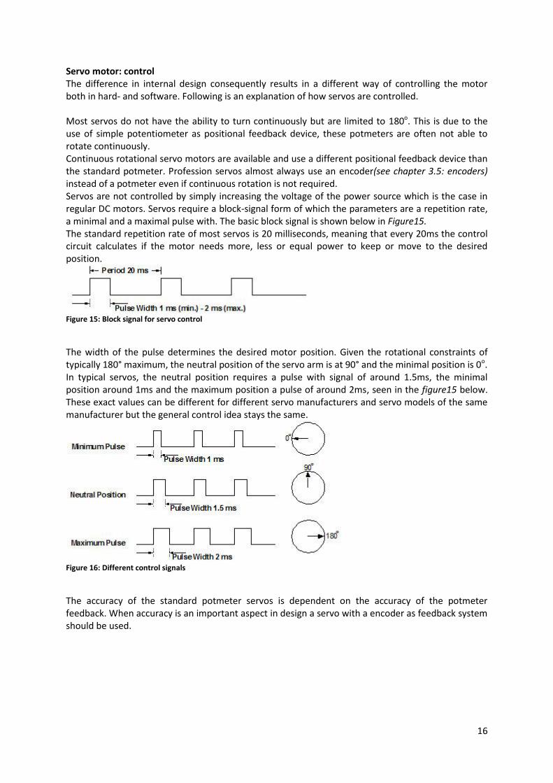
Servo motor: control The difference in internal design consequently results in a different way of controlling the motor both in hard- and software. Following is an explanation of how servos are controlled. Most servos do not have the ability to turn continuously but are limited to 180o. This is due to the use of simple potentiometer as positional feedback device, these potmeters are often not able to rotate continuously. Continuous rotational servo motors are available and use a different positional feedback device than the standard potmeter. Profession servos almost always use an encoder(see chapter 3.5: encoders) instead of a potmeter even if continuous rotation is not required. Servos are not controlled by simply increasing the voltage of the power source which is the case in regular DC motors. Servos require a block-signal form of which the parameters are a repetition rate, a minimal and a maximal pulse with. The basic block signal is shown below in Figure15. The standard repetition rate of most servos is 20 milliseconds, meaning that every 20ms the control circuit calculates if the motor needs more, less or equal power to keep or move to the desired position.
Figure 15: Block signal for servo control
The width of the pulse determines the desired motor position. Given the rotational constraints of typically 180° maximum, the neutral position of the servo arm is at 90° and the minimal position is 0o. In typical servos, the neutral position requires a pulse with signal of around 1.5ms, the minimal position around 1ms and the maximum position a pulse of around 2ms, seen in the figure15 below. These exact values can be different for different servo manufacturers and servo models of the same manufacturer but the general control idea stays the same.
Figure 16: Different control signals
The accuracy of the standard potmeter servos is dependent on the accuracy of the potmeter feedback. When accuracy is an important aspect in design a servo with a encoder as feedback system should be used.

17
Stepper motor: control These motors work on a stepped signal control that energizes the electromagnets surrounding the rotor. As stated before, the rotor of a step motor has teeth which are attracted to the electro magnet when energized. The explanation given earlier on how stepper motors work is good for understanding the basics, but is not often used in real live. This is because when there is no overlap in-between the steps and the motor has to move a load, it is possible that the rotor ´slips´ at the moment of transition between the two electromagnets. The comparison between different types of stepping signals can be seen below in figure18. Full stepping has the same amount of steps as the wave drive but has the benefit of always having two magnets turned on. This ensures there is no powerless moment at every step. Maximum torque is achieved at this drive technique. Half stepping alternates between having two magnets on and having one of. This doubles the angular resolution but comes at the cost of torque. At the full step position, where only a single electromagnet is on, it has approximately 70% of its maximum torque. Micro stepping increases the angular resolution the most. Often called ´sine cosine microstepping´ here the incremental steps are reduced to a theoretically continuous spectrum of axial rotation. By increasing the amount of microsteps, more positions between complete steps are created. This does not however create a reliable increase in accuracy. The amount of torque delivered by every individual microstep decreases by increasing the amount of microsteps per full step, as can be seen below in figure19. Due to this decrease in torque, not every microstep will result in movement of the shaft. It may take the torque of several microsteps combined to overcome the friction in the motor. Reducing the mechanical and electromagnitic noise is the real benefit of microstepping. The transmission of torque will be more general resulting in less resonance problems, increasing the confidence of a synchronised open looped system and less wear on the motor.
Figure 18: Different stepper motor driving signals. Figure 17: Torque vs microstepping
18
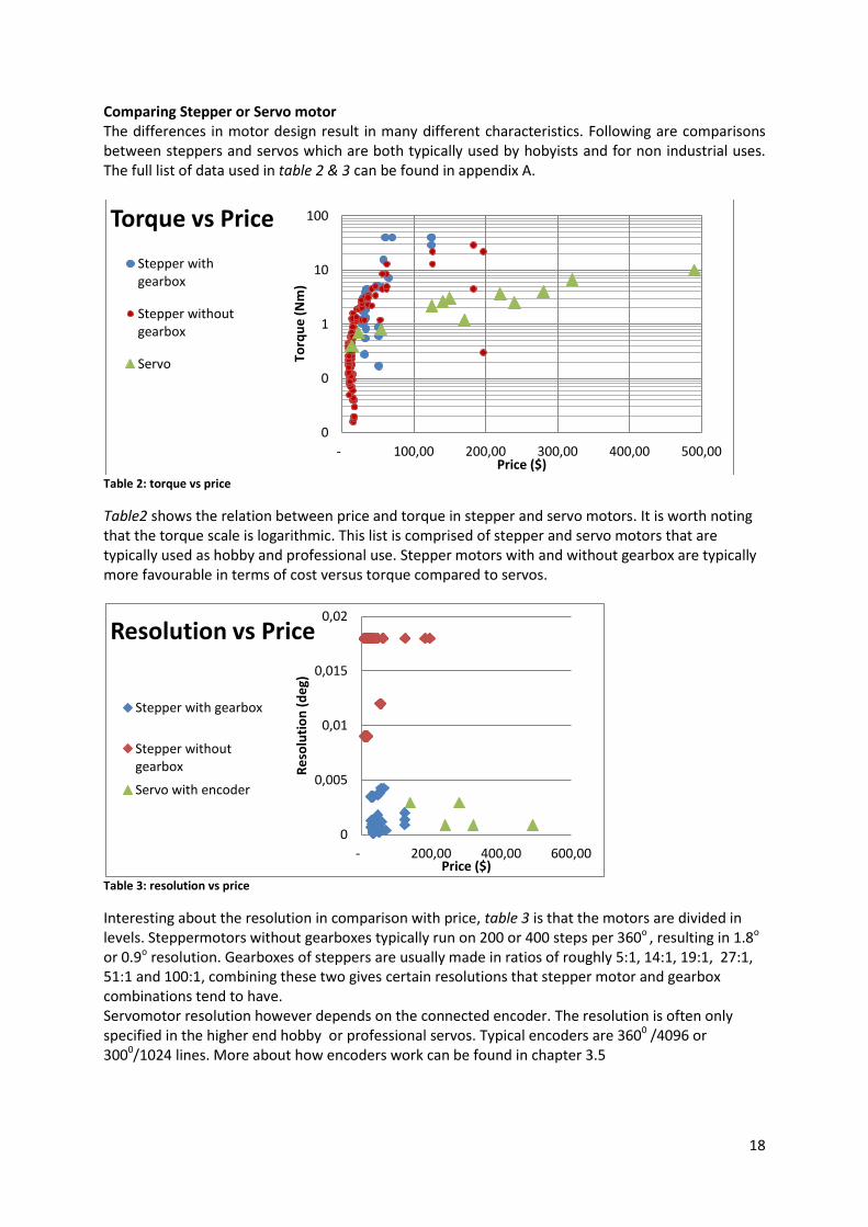
Comparing Stepper or Servo motor The differences in motor design result in many different characteristics. Following are comparisons between steppers and servos which are both typically used by hobyists and for non industrial uses. The full list of data used in table 2 & 3 can be found in appendix A.
Table 2: torque vs price
Table2 shows the relation between price and torque in stepper and servo motors. It is worth noting that the torque scale is logarithmic. This list is comprised of stepper and servo motors that are typically used as hobby and professional use. Stepper motors with and without gearbox are typically more favourable in terms of cost versus torque compared to servos.
Table 3: resolution vs price
Interesting about the resolution in comparison with price, table 3 is that the motors are divided in levels. Steppermotors without gearboxes typically run on 200 or 400 steps per 360o , resulting in 1.8o or 0.9o resolution. Gearboxes of steppers are usually made in ratios of roughly 5:1, 14:1, 19:1, 27:1, 51:1 and 100:1, combining these two gives certain resolutions that stepper motor and gearbox combinations tend to have. Servomotor resolution however depends on the connected encoder. The resolution is often only specified in the higher end hobby or professional servos. Typical encoders are 3600 /4096 or 3000/1024 lines. More about how encoders work can be found in chapter 3.5
0
0
1
10
100
- 100,00 200,00 300,00 400,00 500,00
Torq
ue
(N
m)
Price ($)
Torque vs Price
Stepper with gearbox
Stepper without gearbox
Servo
0
0,005
0,01
0,015
0,02
- 200,00 400,00 600,00
Re
solu
tio
n (
de
g)
Price ($)
Resolution vs Price
Stepper with gearbox
Stepper without gearbox
Servo with encoder

19
Torque vs Speed The actual speed and acceleration a motor depends on the load it needs to accelerate. Manufactures often don't provide information about the torque rating at different speeds, however, some general statements can be made about the relationship between torque, speed and the types of motors. Stepper motors are typically not suited for high speed applications since their output torque decreases as speed increases, typically stepper motors lose 80% torque at 90% no load speed. Servo motors are better suited because they can hold their rated torque till 90% no load speed. At low speed both stepper and servo motors are capable of delivering high amounts of torque.
Setup complexity Stepper motors are almost plug and play. They can be setup easily by connecting the motor to the driver. A servo is more difficult to setup due to its PID feedback system. With a driver suited for a specific motor it does work plug and play but tuning may be required when buying the motor separately from its driver. Safety Servo motors can come with force feedback that can detect a collision with for example a person and be programmed to stop when this is detected. Stepper motors on the other hand do not have this type of detection. Servos may suffer permanent damaged if mechanically overloaded, whereas stepper motors suffer only damage if the gearbox is overloaded. Power to weight ratio Stepper motors are less efficient compared to servo motors which usually leads to a smaller power to weight ratio. Efficiency Stepper motors do not use feedback, resulting in them consuming all the power, providing full torque all the time. Power consumption of servos does depend on the load, resulting in less power consumed with a light load Noise Servo motors operate while producing little noise. Stepper motors tend to have a slight hum due to the control process, this hum is reduced by using a quality driver.
Table 4: Torque versus Speed

20
When to choose a servo or a stepper motor With this information it is possible to make a informed decision about the choice of motor. Servo motors are the ideal solution with a dynamic payload that needs to start and stop really fast. This is because their advanced control algorithms can measure the amount of force being delivered and checking that to the acceleration of the load. This also helps reduce noise. The reserve power they can deliver for short burst of time makes them good at accelerating loads. When handling fragile loads, servos are the best choice, since they can give feedback on the amount of pressure they exert. The downsides to servos are that they cost more and their more advanced operating system makes the setup more difficult. Stepper motors are a good choice when operating at low speeds and acceleration. Here they have no disadvantage in torque over servo motors. Steppers can also handle static torque better than servos for long amounts of time. Another benefit is their price and simpler operating. Steppers are the best choice when performances do not have to be the highest, and money and programming skills are not in abundance.

21
3.2 Bearings A robotic arm consists of a lot of moving parts and it is important that the whole construction moves smoothly and error free. Choosing the correct bearings will contribute to a good robot arm design and understanding the differences and similarities between bearings will help in making an informed decision. Bearings come in all shapes and sizes, all made for different purposes and optimized for different specifications. Generally speaking, a bearing constrains unwanted motions and facilitates only the desired motion. Typical bearings consist of two rings with balls or rollers in between them. This doesn't however cover all bearings, types like fluid, magnetic and flexure bearings use different physical traits to constrain motion to only the desired direction. Here I will lay out the varieties of bearings and discuss both advantages and disadvantages, followed by a recommendation of which bearing to use in what part of the robotic arm, resulting in the deep groove ball bearing for the arm joints and the angular contact bearing for the hip joint. Flexure bearing:
This figure 19, is not the type of bearing people think off when imagine bearings. They are however common, as these flexure bearings are used often in day to day live. These bearings work on the principle of bending material. In some cases, like the lids on a tic-tac case or a carton of juice, 180° of rotation is achievable. This large rotation comes at the price of a short durability because the material is being bent beyond its elastic deformation threshold. For applications storing food products for a limited amount of time this poses no problems but this is often not expectable for professional/industrial use.
The industry uses these types of bearings figure 20 in high precision applications such as holding the mirrors in waferstepper machines. These bearings need to rotate only very little, often less than a couple of degrees, ensuring that the material which is flexed stays well within its elastic limit and ensuring no degradation of the material occurs. These flexure type bearings are popular in the precision industry because they can only rotate in the desired direction and
exhibit zero play in the other unwanted directions. Deep grove ball bearing: This is the bearing, figure 21 & 22, are what most people think of when they imagine bearings. They are the most widely used bearing type and therefore come in a very wide range of sizes and specifications. It is likely to find a bearing in this category that fits a product without having to adjust the product to a certain bearing size. It is simple in design, non-separable, suitable for high speeds and require little maintenance. This type of bearing consists of an inner and outer ring with a set of encaged balls rotating in the middle. The spot where these balls make contact with the rings is called the raceway and for this type of bearing it is located at the middle of the rings. The bearing unit contains a lubricant that is sealed in by shields on the outside, the shield simultaneously keeps dirt and other pollutants out.
A deep grove ball bearing can withstand large loads in radial direction and some in axial direction. The inner raceway is able to turn axially relative to the outer raceway. It has to be noticed that these bearings can also be optimized to be electrically insulating, withstand high temperature, and even withstand chemical erosion. These are however specially engineered products and will not be used in the design for the
robot arm.
Figure 19: Flexure bearing
Figure 20: Flexure bearing, industrial
Figure 21:Deep gove ball bearing Figure 22:Deep
grove ball bearing

22
Needle roller bearings These bearings, figure 23, can only accommodate forces in the radial direction. Their advantage lays in their small diameter relative to its length, which makes them more suitable for bearing arrangements where radial space is limited. To reduce more radial space it is possible for some design variants to be used without an inner or outer ring.
Thrust ball/cylinder bearings In a way these bearings, figure 24 are the complete opposite of deep grove ball bearings. They can only accommodate loads in the axial direction and none in their radial direction. They aren't sealed so there is no lubrication sealed on the inside. A variant on this design is the cylindrical roller thrust bearing, figure 25 , which uses rolling cylinders instead of balls. These can handle heavier loads and absorb shock better.
Angular contact ball bearings These bearings have their raceways displaced relative to each other in the direction of the bearing axis, as can be seen in figure 26. This gives them the ability to accommodate loads in the radial and axial direction of the bearing axis. The loading capacity in the axial direction is determined by the contact angle α. Contact angle α is the angle between the line going through both contact points of the ball and the raceways in the radial plane, and a line perpendicular to the bearing axis. Increasing the contact angle increases the axial load carrying capacity and vice versa. With the correct amount of pretention the play of this bearing can be theoretically be reduced to zero. More about the subject of play will be explained later in the section 'Play in bearings'.
Figure 23: Needle roller bearing
Figure 25:Thrust roller bearing Figure 24: Thrust ball bearing
Figure 26:Angular contact bearing

23
Tapered roller bearings Just like angular contact bearings, these tapered roller bearings, figure 27&28
can accommodate loads in both axial and radial directions while allowing rotation around the axis. This design incorporates rollers instead of balls, increasing the contact area and thus increasing the maximum load. Just as in the angular contact bearing, the axial load bearing capacity increases with an increase of the contact angle.
Spherical roller thrust bearings A variant on this design is the spherical roller thrust bearing, figure 29&30. These bearings have rollers which are rounded, giving them the ability to self align and to accommodate a misalignment of the shaft, which could be caused by a deflection in the shaft.
Self aligning ball bearings
These bearings, figure 30&31 have a double row of balls in a shared spherical raceway in the outer ring. This allows them to accommodate large angular misalignment of the shaft while still maintaining its working function of a bearing.
Figure 27:Tapered roller bearing Figure 28: Tapered roller bearing
Figure 30:Spherical roller thrust bearing Figure 29:Sperical roller thurst bearing
Figure 32:Self aligning ball bearing Figure 31:Self aligning ball
bearing

24
Selecting the right bearing To find the correct bearings for the different joints in the robotic arm it is needed to analyze the requirements and select the correct bearings for the application. The chart below gives a quick comparison about the different characteristics of the different types of bearings.
In robot arms of the articulate type a typical divide can be made between the bearing used in the hip of the robot versus the bearings in the arm of the robot. The hip bearings are always presented with high axial and radial loads. Unless super high precision, and a low amounts of rotation are required the angular contact bearing and tapered roller bearings are often the best choice here. For industrial uses where heave loads, fast acceleration and long hours of operation occur, tapered roller bearings are the best choice. For smaller home robots these extra high performances are not needed, angular contact bearings will suffice. For the arm part of the robotic arm, deepgroove ball bearings usually suffice for small sized non industrial arms. They are great for radial loads and can manage the light axial loads that occur when the arm accelerates and decelerates in rotation. When more extreme performance is required, for example in industrial applications, carrying heavy loads with high inertia-, requiring fast acceleration and long operating hours, angular contact bearings are often required. Deepgrove ball bearings would not be able to handle the axial loads in these situations.
Characteristics Bearing type
Accepts forces
Allows misalignment
Play Load capability
Thickness Price availability
Flexure bearing (industrial)
Radial & Axial
No None Normal Average $$$ -
Flexure bearing (commercial)
Radial No Small Low Thin $ +++
Deep grove ball bearing
Radial &Small axial
No Small Normal Average $ ++
Needle roller bearing
Radial No Smaller High Thin* but wide
$$ +/-
Thrust ball bearing
Axial No Small Normal Average $ ++
Angular contact ball bearing
Radial & Axial
No None theoretically
Normal Average $$ +
Tapered roller bearing
Radial & Axial
No None theoretically
High Thick $$$ +/-
Spherical roller thrust bearing
Radial & Axial
Limited Limited Normal Thick $$$ +/-
Self aligning ball bearing
Radial Yes Unlimited Low Thick $$$ +
Table 5: Bearing characteristics

25
3.3: Power transmission The rotational force produced by an electric motors has to be transmitted to the part of the frame it is driving. This can be done by either directly connecting the motor shaft to the frame by using a flange or using a power transmitting medium. Connecting the motor directly can have the advantage of not losing any power in transferring and not risking having any of the drawbacks like backlash caused by a transmission system. It does however also bring downsides like restraints in design. Here some of the possibilities of power transmissions will be explained and at the end an advice is given on what type of transmission to use for which motor. When mounting the motor directly, the motor shaft and the arm need to have the same axis of rotation. This will either result in the motor shaft being the actual axel the arm sits on, the motor and its shaft sticking out of the product giving it enough room for a shaft coupling piece, or the shaft needs to be long enough to reach through the frame, the bearing supporting the arm and have enough space left to attach a mounting flange. Depending on the type of motor, there may already be a bearing in place at the end of the motor giving the motor axis a radial force rating of up to 100N. When loading weight on the output shaft like this, careful consideration towards the axial loading force should be taken, since heavy loading of the motor shaft can results in more wear of the motor and a shorter service life. Using a set of pulleys and a timing belt, figure 33, is also an option. The robot arm can now sit on an axel and the motor only has to provide rotational force. Because a belt drive can go both ways, it can push and pull the load to both sides. Another benefit is that backlash from the gearbox of the motor can be reduced by the gearing of the pulleys. If the ratio of the pulleys is 2:1 and the gearbox backlash is 1deg, this will be reduced to 0.5deg. The possible backlash occurring in the pulleys does need to be added to this figure. By using a reducing gear ratio, the motor power is increased even more and the rotation speed is decreased.
This should be taken into account when sizing the motor. Belts can also be used over a long distance without needing to be strengthened to eliminate the problem of buckling which could appear in a push rod. Preload or pretention on the belt is required since the lack in the belt pretention would cause backlash. The internal bearing of a motor with gearbox can handle this amount of pretention. Another way to attach the motors to the part of the robot arm it is driving would be to use an lever attached to the motor. A drawback of this option is that although rods are excellent at handling pulling forces they are not as suitable for pushing. When rods are used to push they may buckle under the load, this can however be reduced by folding over the edge of the rod. This little extra width creates a lot of extra stiffness. The use of pushrods as a lever system to transmit power can also reduce the backlash of the motor but can do this at most with a factor of 2:1. This is because after the motor has turned 1800 deg (half a turn) the connecting rod will reverse direction.
Figure 33: Belt and pulley system

26
A cardan or flexible drive shaft can also be used to transmit power over a distance. They can typically be found in cars, going from the engine gearbox to the rear wheels. Cardans have as advantage that they can transmit large amounts of torque and are not negatively affected by high speed which makes them ideal for the use in cars. To transmit the same amount of power as a belt or chain, a cardan weighs significantly more. This is not a problem in cars since they do not have to be lifted up and down continuously, but does pose a problem when implemented in a robot arm. Another problem is that in a cardan the rotation needs to change direction, using a set of gears or couplings. The use of these will increase the amount of backlash in the system and thus decrease the accuracy. A flexible drive shaft is in essence multiple small cardans with flexible couplings, more angular misalignment between the in and out of the shaft requires more couplings resulting in more backlash. The use of a lever system, the use of a timing belt and mounting the motor directly have clear benefits over the use of cardan. To make an informed decision on the possibly using a timing belt it is important to know more how they work. Timing belts can be built with a number of tooth profiles and a number of material compounds making up the teeth, body and tension members of the belt. The different strengths and weaknesses of the different tension members are summarized in figure34. Important for a robotic arm are high torque at low speed, low belt stretch, dimensional stability and rapid start/stop operation. Glass fibre and stainless steel are the best choice of tension member according to the graph. The notable
exception being the rapid start/stop operation, where the stainless steel scores a lot higher.
Another aspect of the timing belt is type of teeth it uses, see figure 35, its rated horsepower, figure 36 and allowable working tension figure 39. Different brands produce different types of teeth profiles, ranging from trapezoids to semi circles resulting in different characteristics. Most notable are the types HTD and GT "HTD was developed for high torque drive applications, but is not acceptable for most precision indexing or registration applications. The HTD design requires substantial belt tooth to pulley groove clearance (backlash) to perform" "PowerGrip GT2 belts are specifically designed for applications where precision is critical, such
as computer printers and plotters, laboratory equipment and machine tools "(Handbook of timing
belts and pulleys, by sdp-si)
Figure 34: Timing belt tension member compounds
Figure 35:Timing belt profiles

27
The backlash from timing belts can be minimal as shown by figure 37&38. The backlash on a pulley with diameter 6.37mm is 0.013mm. This results in a backlash angle of 0.230 deg. To put this into perspective, backlash from a typical off the shelf stepper motor with gearbox is often classified as <10 deg, or when high reduction is produced (100:1) it is sometimes <1.50 deg. By using a combination of reducing gearbox and reducing timing belt drive, the same torque can be realized while reducing the total backlash, since the motor backlash is reduced with the pulley ratio. By using a 3:1 timing belt drive with a 33:1 gearbox, the same torque is realized as a 100:1 gearbox
which is usually rated at <10 deg backlash. This combination has a <
= <0.560 deg
Seeing all the strengths of the timing belts, being able to both push and pull, reducing backlash, adding little weight and not having to bear the weight of the arm and no chance of buckling under load while transmitting the power over a long distance makes it a viable way to transmit power from the motor at the base of the frame to the elbow joint, connecting to the lower arm. A pushing rod which is bent at the top for added stiffness is also a viable option. For the hip motor the use of a reducing timing belt would also be the most beneficial. The GT series is the most promising, since it has the highest working tension and the lowest backlash. The drawback of this is that their tension cords are made of fibreglass which is not good at handling rapid starts and stops, these will have to be ramped to ensure long belt life. The upper arm may be best connected directly to the motor. This is because the shoulder arm has to provide the largest torque and the power does not have to be transmitted over a long distance. A connecting rod system would also be possible since the chance of buckling will be small due to its short distance, this is not recommended however due to the increased complexity.
Figure 36: Timing belts vs Horsepower Figure 37: Timing belt design and their precision error
Figure 38: Timing belt backlash Figure 39:Timing belt tension

28
3.4: Frame There are many ways to build the frame of a robotic arm, different material and different profile forms and shapes influence the strength and elasticity of the robot. With the help of 3D modelling software it's possible to look at different design options and their influence on the weight of the arm and the amount of deflection. It is possible build the robotic arm arms out of cylindrical or rectangular tube profile and good, often stronger designs may follow from using this as starting material, but the use of this complicates the design of the frame, installation of its components and manufacturing. 3D printing houses a range of possibilities for robotic arms as well. Through optimization software it may be possible to print the parts needed in the robotic arm which are more advantageous strength to weight ratio due to internal strengthening structures. One of the drawbacks of 3D printing however is that plastics are often used as base material. Plastics tend to bend more easy than metals, and optimizing the frame and 3D printer parameters is a difficult process involving trial and error. 3D printed parts could have potential if already optimized and available for download, however for a single piece production the design and optimization process makes it so that it is not easy to make at home. Using sheet material as starting material makes it possible to send the 3D modelling files to a range of companies offering commercial laser or water jet cutting. The use of sheet material also adds the advantage of the user being able to make their own choice of material depending on what they have available to them using what they are comfortable with.
It is possible to calculate deformation by hand, by using the formula
, but this only works
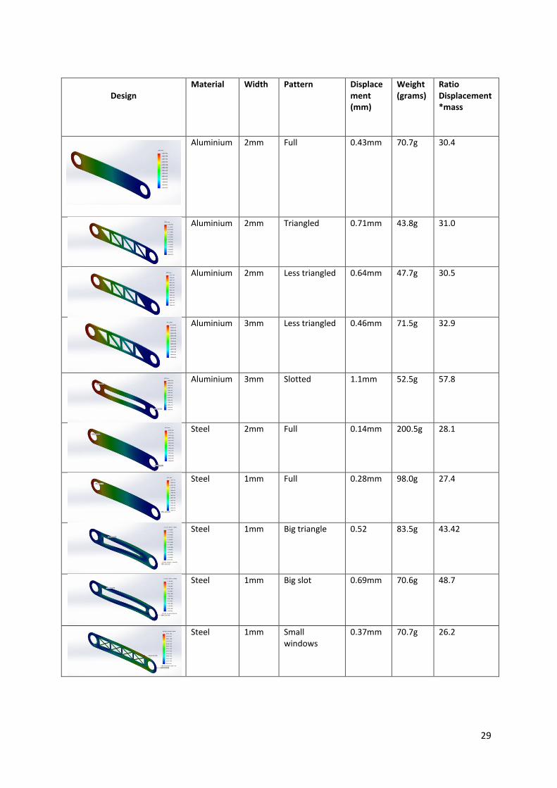
when the cross section of the beam is kept constant along the entire length. To see what type of deformation could occur in the arm pieces and see if reducing weight by removing material is a good design strategy, a simple arm is modelled and tested with SolidWorks software. The basic shape of one of the arm pieces used for analysis, see figure 40, is a long piece of sheet metal with the dimensions of 300x50mm with rounded ends. The holes at the ends have a diameter of Ø24 and are the places where the arm is connected to the other parts of the robot. A load of 100N (roughly 10kg) is placed in one hole while the other is fixed. These values are constant trough multiple design variations. The following results are made by SolidWorks 2014; SimulationXpress The full SimulationXpress study results can be found in Appendix B. The materials used as test materials are Aluminium Alloy 1060 and Steel Alloy from the stock SimulationXpress library. Following is a table summing up the results of various design variations with various materials, material thickness and patterns to remove material. The ratio of displacement * weight can be used to compare the results. Ideally this ratio should be as low as possible, that indicates the least amount of displacement with the least amount of weight
Figure 40: Basic arm shape
29
Design Material Width Pattern Displace
ment (mm)
Weight (grams)
Ratio Displacement*mass
Aluminium 2mm Full 0.43mm 70.7g 30.4
Aluminium 2mm Triangled 0.71mm 43.8g 31.0
Aluminium 2mm Less triangled 0.64mm 47.7g 30.5
Aluminium 3mm Less triangled 0.46mm 71.5g 32.9
Aluminium 3mm Slotted 1.1mm 52.5g 57.8
Steel 2mm Full 0.14mm 200.5g 28.1
Steel 1mm Full 0.28mm 98.0g 27.4
Steel
1mm Big triangle 0.52 83.5g 43.42
Steel 1mm Big slot 0.69mm 70.6g 48.7
Steel 1mm Small windows
0.37mm 70.7g 26.2

30
Steel 1mm Medium windows
0.39mm 64.9g 25.3
Steel 1mm Large windows
0.56 51.6g 28.9
Steel 1mm Large windows small support
0.54 55.0g 30.0
Steel 1mm Large windows bigger supports
0.52mm 58.9g 30.6
Steel 1mm hexagons 0.56mm 61.4g 34.4
Steel 2mm Topological optimized via PareToWorks
0.15mm 133g 19.9
Table 6:Topological strategies
As can be seen in table 6, all different designs result in different displacements at the end. All but the last design was made by hand and although some of them improve the weight to displacement ratio, they do not do so drastically. The last analysis is done on a arm which has been topologically optimized by a computer simulation program called PareToWorks. PareToWorks is a add-on to SolidWorks and uses a finite element analysis to optimize a part for least displacement, stress, weight and other properties. The free trial version of this program was used to reduce the weight of the material while minimizing extra occurring displacement. Analysis of this part shows that this part is more efficient at reducing material and keeping displacement to a minimum, with a ratio of 19.9 compared to using basic shapes and patterns with at best a 25.3, and the original at 28.1

31
3.5 Encoders To get the arm to the desired location with high precision and certainty, an encoder is required. Most professional servos come with an internal encoder already built in and encoders can be added to steppermotors to make them a closed looped system. Two types of radial encoders are available, incremental and absolute encoders. Incremental encoders, figure 41, are relatively simple and can detect motion in increments. They work by having a light source shine through slotted disk connected to the motor shaft. As the shaft turns the beam of light shines through the slits and is broken up by the disk at a certain frequency. This frequency determines the speed of rotation, and the amount of light pulses determines the turn angle of the shaft. The incremental encoder can only measure speed and distance travelled and has no way of telling the absolute position of the shaft angle, it is therefore required to calibrate the motor every time it is turned on to determine its position. Absolute encoders, figure 42 are able to tell the absolute angle of the shaft. It achieves this by having a disk with multiple rings that can absorb or reflect the light shone on them. Every ring is a bit in a binary system and a reflected light source sends a 1 signal whereas a absorbed light beam results in a 0 signal. When a disk has 5 rings it can give 25 =32 discrete angles of the shaft of 11.5° degrees each. Figure 42 is a simple example of an encoder disk, other commercial encoders have, for example, 4096 discrete angles, resulting in 0.008° of resolution. These encoders can always know at what angle the shaft is and do not need to be calibrated for every use.
3.6 Backlash Backlash phenomenon that occurs in systems using gears or gear trains. It generates precision problems in controlling the position of the end effectors attached to the gears. Gear teeth always have a little clearance in between them, figure 43, to allow for smooth operation, to allow possible lubricant and to reduce friction, resulting in reduced wear of the gears. Backlash occurs when the contact side of gears change. The driving gear has to first overcome the clearance between the gears before the driven gear starts turning
In the shoulder joint, the contact side of gears switch when the arm has to be pushed down, and when the motor has finished moving the arm up but the inertia continues lifting the arm further. Because there is always the load of the arm itself trying to pull the arm down, figure 44, when the movement stops, the weight of the system will force the motor to work against gravity ensuring the same contact side between the internal gearbox gears. When a robotic arm is used to press something down like
Figure 41: incremental encoder
Figure 42: absolute encoder
Figure 43: backlash visualized
Figure 44: robot arm simplified

32
a electric screwdriver, it does first have to overcome this backlash before it can start applying preasure.
The same is true for the gears in the elbow joint.
When the motor stops moving, the gravity of the
system causes the motor to hold the load, reducing
the effect of backlash in the system. figure 45
Where backlash does become a problem is at the hip
joint. The purpose of this joint is to rotate the arm
around its base, figure 46. It can constantly change
direction of rotation and has no constant force acting on the gears to ensure the same side of them is
engaged at all times. It is important to consider the importance of backlash at this point, and to
choose a motor with only a small amount of backlash if necessary.
Figure 47: robot arm topview
Anti backlash nuts and gears
There are ways to reduce backlash between gears and lead screws. One of the possibilities to combat the backlash is a anti backlash nut, figure 48, or gear,figure 47. This system uses a spring to connect two nuts or gears, making sure that both nuts or gears have an opposite contact surface engaged. Because the spring provides tension in these systems they are not capable of transmitting large forces because if the spring would be strong enough to not be compressed when the force of, for example, a lath is applied they would provide too much friction between itself and the gear or shaft moving it. They are thus not able to transmit large forces.
When large forces need to be transferred, a split nut can be useful. This is a nut which is
cut length wise with an adjustment bolt. This bolt can be tight until the thread on both sides touches. There still needs to be a tiny amount of play between the thread to allow smooth movement between them but this can be a lot less than it originally was. The problem with these anti backlash gears and nuts is that they only reduce the backlash between itself and the object it is engaged with. These cannot be used to take up the entire backlash produced in a gearbox. A timing belt could be used to reduce backlash from the gearbox. There are timing belts available which only have 0.12deg backlash, and by using a 3:1 reduction setup, the backlash of the motor is reduced to a third of its original, while adding 0.12deg to the total.
Figure 45: robot arm side view
Figure 48:anti backlash nut
Figure 46: anti backlash gear

33
4: How components effect performances This chapter will relate components and their effect on performances. Starting off by relating bearings to accuracy in section 4.1. Later, a mathematical model is shown to determine the required torque of a motor given a certain payload and acceleration in section 4.2. Lastly precision and accuracy will be related to resolution of motors, in section 4.3.
4.1: Bearing influence accuracy. Modern production methods can create the balls and rings for bearings with a precision of a couple of micro meters (10-6m). For bearings with fixed inner and outer rings to work smoothly it is necessary to always have some amount of clearance build in in-between the balls and the raceway. Not having any clearance would increase rotational resistance due to friction, would limit the lubricating capabilities of the lubricant and would decrease the lifespan of the bearings. Deep grove ball bearings have this clearance but in angular contact bearings this clearance is determined by the way it is mounted. This clearance is called Internal Radial Clearance and is dependent on the bore diameter of the bearing. For most applications of bearings this isn't a problem since a thousandths of a millimetre misalignment in a bike wheel is not significant. When designing a robot arm that has to have precision far away from the bearing, these seemingly unimportant clearances are magnified by the arm and can become a problem for its accuracy. It is possible to determine the theoretical maximum amount of play a bearings has and what effects this will have on the accuracy of the end-effector. Working backwards by taking the maximum allowed accuracy error (due to bearings) and determining what bearings are needed and if they can possibly meet up to the standards is also possible. What will follow is a way to calculate the theoretical maximum amount of play induced by a bearing, depending on its size specifications.
Bore diameter (mm) (10^-3m) min max
Radial Internal Clearance (μm) (10^-6m) Min max
2.5 6 2 13
6 10 2 13
10 18 3 18
18 24 5 20
24 30 5 20
30 40 6 20
40 50 6 23
50 65 8 28
65 80 10 30

34
Calculations: D = outside diameter b = bore (inside diameter) c = internal radial clearance e= thickness of the bearing raceways f= distance from inside to middle of the raceway l = distance from bearing centre to ball centre
Angle α dependent on the length l and height c. From the formula for angle α, we can logically deduct that the biggest value for angle α occurs at the smallest value of l and the biggest value of c As stated before, deep grove ball bearings come in a lot of sizes, one producer offers more than 150 types in the bore diameter range from 3 to 10mm. To give a general indication of the values we are talking about, some of these bearings have been selected and are shown in
Bore Ø b (mm)
Outside Ø D (mm)
Clearance c (μm)
l (mm)
Deg displacement at 30cm
3 10 13 3.26 .025o 0.131mm
4 13 4.26 .019 o 0.099mm
5 16 5.26 .015 o 0.079mm
6 19 6.26 .013 o 0.068mm
7 23 7.51 .011 o 0.058mm
8 24 8.01 .010 o 0.052mm
9 26 8.76 .009 o 0.047mm
10 29 9.76 .008 o 0.042mm Table 7: bearings and resulting play
Figure 49: bearing simplified

35
Single or double sided bearing placement Many variants of robot arms are out there, all with their own strengths and weaknesses. Some use arms which are connected by just one bearing and some use bearing pairs in parallel. When only a single bearing is used in the shoulder and elbow joint, see figure 50, the play angle α of
the shoulder bearing is added to the play angle of the elbow bearing, magnifying the effect it has on
its accuracy, see figure below.
Using bearing pairs in parallel in both the shoulder and elbow joint prevents this problem. The lengths of the arm 'x', see figure 51 stays constant. Creating a parallelogram in the frame, insuring that the axis are parallel to each other. Resulting in only the displacements caused by the play angle adding up instead of the angles themselves combining.
Figure 51: double sided bearing placement
Adding a support structure, figure 52, like a spacer tubes, and clamping the frame onto them with nuts and bolts will greatly reduce the play. This is because the spacer create their own play reducing parallelograms.
Figure 52:double sided bearing placement with supports
Having a round or square tubular profile as a frame for the arm will result in the least possible play in the system. This comes with the trade-off off adding extra weight to the arm.
Figure 50: single sided bearing placement
36
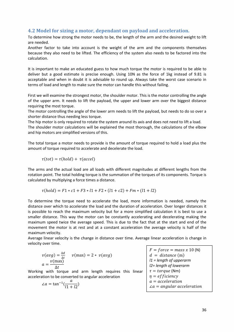
4.2 Model for sizing a motor, dependant on payload and acceleration. To determine how strong the motor needs to be, the length of the arm and the desired weight to lift are needed. Another factor to take into account is the weight of the arm and the components themselves because they also need to be lifted. The efficiency of the system also needs to be factored into the calculation. It is important to make an educated guess to how much torque the motor is required to be able to deliver but a good estimate is precise enough. Using 10N as the force of 1kg instead of 9.81 is acceptable and when in doubt it is advisable to round up. Always take the worst case scenario in terms of load and length to make sure the motor can handle this without failing. First we will examine the strongest motor, the shoulder motor. This is the motor controlling the angle of the upper arm. It needs to lift the payload, the upper and lower arm over the biggest distance requiring the most torque. The motor controlling the angle of the lower arm needs to lift the payload, but needs to do so over a shorter distance thus needing less torque. The hip motor is only required to rotate the system around its axis and does not need to lift a load. The shoulder motor calculations will be explained the most thorough, the calculations of the elbow and hip motors are simplified versions of this. The total torque a motor needs to provide is the amount of torque required to hold a load plus the amount of torque required to accelerate and decelerate the load.
The arms and the actual load are all loads with different magnitudes at different lengths from the rotation point. The total holding torque is the summation of the torques of its components. Torque is calculated by multiplying a force times a distance.
To determine the torque need to accelerate the load, more information is needed, namely the distance over which to accelerate the load and the duration of acceleration. Over longer distances it is possible to reach the maximum velocity but for a more simplified calculation it is best to use a smaller distance. This way the motor can be constantly accelerating and decelerating making the maximum speed twice the average speed. This is due to the fact that at the start and end of the movement the motor is at rest and at a constant acceleration the average velocity is half of the maximum velocity. Average linear velocity is the change in distance over time. Average linear acceleration is change in velocity over time.
Working with torque and arm length requires this linear acceleration to be converted to angular acceleration
(N)
l1 = length of upperarm l2= length of lowerarm (Nm)

37
The torque needed to accelerate can now be calculated by multiplying the moment of inertia by the angular acceleration.
This results in the formula for required torque:
Efficiency loss occurring in the gearbox of the motor is already calculated into the torque specification provided by the seller. The robotic arm as a system can also cause some inefficiency, also needing to be factored into the equation. A 90% or factor 0.9 is a good estimated value. This brings the complete required torque formula to be :
The torque required for the elbow motor is calculated in mostly the same way, with the exception of the upper arm and elbow axel being left out and the distances being shorter.
The waist motor only has to accelerate, not lift the load. It does have to do so at the same distance as the shoulder joint, resulting in the following formula.
It is important to note the motor should at least be able to handle these loads and should be capable of more. Running a motor close to or at the maximal specified torque rating for long is not good for its service live. Even though these calculations are based on the worst case scenario of the maximum load at the maximum distance of a fully stretched out horizontal arm, which is not likely to occur, it is advised to add in a margin of extra torque as a safety factor. Buying a motor one step stronger is a smaller investment than replacing a motor.

38
4.3 Determine the resolution of a motor The accuracy of a motor is also partly dependant on its resolution. For servo motors this is the resolution of their encoders, for a stepper it is the step size after the gearbox. Often, this resolution is given in the specification sheet of the manufacturer either in degrees, steps/rotation or lines/rotation angle Step/rotation can be converted to degrees in the following way:
( )
lines/ rotation can be converted in the following way:
( )
When a motor is connected to a gearbox and the resolution is given before this gearbox it needs to be multiplied by the gearratio. To find the resulting positional change one increment has on the end effector we use the following formula. Having a motor with a resolution of 4096 per 3600 results is 0.0880 per incremental step. When the arm length is 30cm, this results in
4.4 Predicting the accuracy of the arm The total static accuracy of the robot arm is the combined inaccuracy of all the parts in the arm causing inaccuracy. These are the bearings, motors, transmission and deflection of the arm. The inaccuracy in transmission is caused by backlash which is always existing, but is only expressed when the gears switch contact sides. The deflection of the arm is dependent on the load and the profile of the arm, calculating it by hand is possible for arms with constant cross section but is better done by a computer when this is not the case. The formula for total static inaccuracy d is: Calculations for these can be found in chapter 4.1, 4.3, 3.3+3.6 and 3.4 respectively. However, not all sources of inaccuracy work in the same plane, these inaccuracy would in reality describe a sphere of possibilities where the endeffector can be located. The direction of inaccuracy should be taken into consideration when adding these values.

39
5 Design brief When manufacturing a robotic arm, specifications in performance result in the selection of the components used. For this project the following design brief outlines the desired performance of the robotic arm to build. The knowledge gathered for this paper will be used to make informed decisions for the robot arm to match this desired performance. General purpose of the prototype robot: The purpose of the robot is to be able to test some of the predictions made in this paper about robotic arms. The prototype should be able to support light loads, such as a pen holder, a filled teacup, a 3D print nozzle or a gripper. To test the accuracy and precision of the robot, a fixture for a pen should be attachable to the arm. By drawing dots at various locations, and evaluating the spread and distance of these dots to the reference values, conclusions can be drawn from these results. Reach: The robotic arm should to sit at the centre of an A2 size paper(4x a4) and be able reach every corner. The diagonal of an A4 paper is 364mm, and this is the desired reach of the arm. Speed/acceleration: The arm should be able to start, move 100mm and stop in 1 second. This speed is decent for a small robot arm and most competitors in this size range are able to reach these speeds. There are other arms available with speeds greatly outperforming this 100mm/s but these come at high cost. Payload: The desired payload is 500g, which is about the weight of a half litre bottle of water, or a filled teacup. Accuracy & precision: The inaccuracy or systematic error should be less than 2mm. The imprecision or reproducibility error should also be less than 2mm. These are the same specifications as commercial robot arms like the do-bot has.
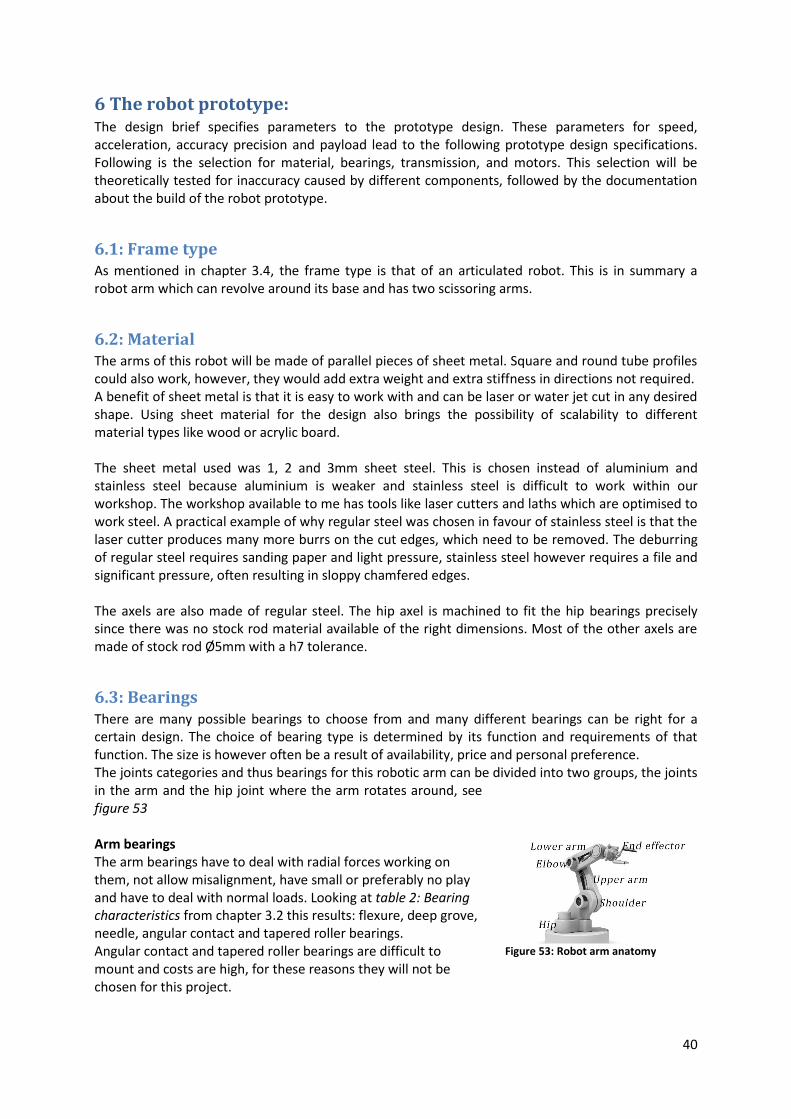
40
6 The robot prototype: The design brief specifies parameters to the prototype design. These parameters for speed, acceleration, accuracy precision and payload lead to the following prototype design specifications. Following is the selection for material, bearings, transmission, and motors. This selection will be theoretically tested for inaccuracy caused by different components, followed by the documentation about the build of the robot prototype.
6.1: Frame type As mentioned in chapter 3.4, the frame type is that of an articulated robot. This is in summary a robot arm which can revolve around its base and has two scissoring arms.
6.2: Material The arms of this robot will be made of parallel pieces of sheet metal. Square and round tube profiles could also work, however, they would add extra weight and extra stiffness in directions not required. A benefit of sheet metal is that it is easy to work with and can be laser or water jet cut in any desired shape. Using sheet material for the design also brings the possibility of scalability to different material types like wood or acrylic board. The sheet metal used was 1, 2 and 3mm sheet steel. This is chosen instead of aluminium and stainless steel because aluminium is weaker and stainless steel is difficult to work within our workshop. The workshop available to me has tools like laser cutters and laths which are optimised to work steel. A practical example of why regular steel was chosen in favour of stainless steel is that the laser cutter produces many more burrs on the cut edges, which need to be removed. The deburring of regular steel requires sanding paper and light pressure, stainless steel however requires a file and significant pressure, often resulting in sloppy chamfered edges. The axels are also made of regular steel. The hip axel is machined to fit the hip bearings precisely since there was no stock rod material available of the right dimensions. Most of the other axels are made of stock rod Ø5mm with a h7 tolerance.
6.3: Bearings There are many possible bearings to choose from and many different bearings can be right for a certain design. The choice of bearing type is determined by its function and requirements of that function. The size is however often be a result of availability, price and personal preference. The joints categories and thus bearings for this robotic arm can be divided into two groups, the joints in the arm and the hip joint where the arm rotates around, see figure 53 Arm bearings The arm bearings have to deal with radial forces working on them, not allow misalignment, have small or preferably no play and have to deal with normal loads. Looking at table 2: Bearing characteristics from chapter 3.2 this results: flexure, deep grove, needle, angular contact and tapered roller bearings. Angular contact and tapered roller bearings are difficult to mount and costs are high, for these reasons they will not be chosen for this project.
Figure 53: Robot arm anatomy

41
Flexure bearings only have a limited degree of rotation if they are used for professional purposes and need to have long life. It is possible for flexure bearings to accommodate the amount of rotation produced by a robotic arm but this will lead to a short lifecycle due to fatigue. This would result in frequent maintenance and possible breakdowns of the system. For these reasons they will not be used in this variant of a robotic arm. Needle roller and deep grove ball bearings are now the only logical contenders for the use of bearings in the arm. The advantages of needle roller bearings are that they take up less radial space and are better capable of supporting heavier and shock loads, both of these are not problems that occur or need to be solved in this robotic arm design. These bearing are also more expensive, harder to install and will require flanges to be attached when the arm is made out of sheet metal. This leaves deep grove ball bearings as the best suitable for the job, they bind the required degrees of freedom sufficiently, are easy to install, well priced and available. The bearings selected for the prototype are flanged deep groove ball bearings F625ZZ and MF105ZZ. These are both bearings both with a bore of 5mm. The difference is in their outside diameter and width, which are 10 & 16mm, and 4 and 5mm respectively. The reason for the use of different bearings is that the smaller bearings fit better in smaller parts. The use of flanged bearings simplifies the assembly of the arm, the flange adds a positional constraint resulting in the bearing axis being perpendicular to its housing sheet metal plate when the bearing is pressed down, eliminating the need to press fitting and aligning. Hip bearings The hip bearing needs to accept radial and axial forces and therefore it requires a different bearing than the ones in the arm. Flexure bearings are not suitable for the same reasons why they are not suitable for the arm joints, namely that they either don't facilitate large degrees of rotation or fail due to fatigue when they do. Spherical roller thrust bearings and self aligning ball bearings allow a (limited) amount of play which is useful when axis misalign or when the load forces slight deformation in the axis. This is however not a wanted property of the hip bearing since it would result in the arm being able to tip over. Tapered roller and angular contact bearings are both sensible choices with the only difference being that one uses ball bearings and the other a tapered roller. The tapered roller bearing can take heavier loads and is better suited to handle shock loads, both not required qualities for this type and size of robotic arm. Combined with the fact that they are more expensive and less readably available, results in the angular contact bearing being the best suited for the job. The hip bearings chosen for the prototype will be the angular contact bearing 7202-BECBP from SKF. The angular contact bearing 7202-BECBP has a bore of 15mm and a outside diameter of 35mm. An axel of 15mm should be strong enough to support the robot arm. Two bearings will support the hip axel, one on top and one on the bottom of the base frame. This is all clamped together by two nuts on either end of the axel.

42
6.4: Power transmission Every motor will connect to its effecter differently, all depending on this particular arm design. The hip motor will be mounted upside down on the frame and the upper and lower arm motors are placed symmetrically on both sides of the shoulder. The hip motor delivers its power through a timing belt to a pulley on the bottom side of the hip axel. The reason to incorporate a timing belt and pulley system is due to the fact that it is not wise to place the hip motor at the centre of the hip. This is possible but would result in loading the motor shaft axially in order to clamp the angular contact bearings together. Making a quick calculation, assuming the arm is 400mm, the load plus weight of the arm is around 700g and the bearing is 30mmØ would
put the axial force at
This is more than the typical 50N a gearboxed electro motor can
handle. This is why the design is chosen where the motor is not located above the hip but instead is placed on the base of the frame. Using the timing belt and pulleys can also reduce the amount of backlash a gearbox would produce and increase the resolution of the motor, which is sensible when used without a gearbox. The drawback of the low backlash gt2 timing pulleys is that they are not suitable for rapid start and stops at high torque, this will however not happen in this prototype. The upper arm motor is directly connected to the upper arm. To keep the design easy, the axis of revolution of the upper arm and that of the upper arm motor are the same. This allows the arm to be mounted with a flange directly to the motor. This is possible since the radial load capacity for many motors with gearbox is 100N. The lower arm motor is also be mounted on the axel as the upper arm. This allows for a simpler symmetrical design. The lower arm is connected by a rod of the same length as the upper arm, and the distance from where this rod connects to the lower and its axis of revolution is the same as the distance from where the rod connects to the motor flange and its axis of revolution. This creates a parallelogram where if the motor rotates 1deg, the lower arm will rotate by the same amount. A push rod system is chosen for this power transmission since the torque being transferred is relatively high, this combined with the knowledge that the gt2 timing belts are not well suited for high torque start stops, makes a push rod the logical transmission of choice.

43
(N) l1 = length of upperarm l2= length of lowerarm c = distance from center of mass to the center of rotation. (Nm)
6.5: Motors To select motors for the robot arm that meet the performances of the design brief, some calculations have to be made. The most important specifications manufactures typically provide with their motors are the amount of torque, if attached the torque rating after the gearbox, stepangle and or position sensor resolution. The performances required of the robot arm are not measured in these unit so they need to be converted. Chapter 4.2 explains this conversion in more details. Following are the calculations done to select the motors in the prototype. Speed /acceleration: The performances given in the design brief for speed and acceleration are: " start, move 100mm and stop in 1 second" and a required arm length of 400mm.
Motor torque: The following calculations result from the payload specification of 500g (5N), the estimate that each arm segment weighs 200g(2N) and the combined weight of the bearings will be 100g (1N) The explanation of the following calculations can be found in Chapter 4.2. These calculations are filled out with the specifications from the design brief and educated guesses about the weight of the arms based on the analysed arms in chapter 3.4
l1 = length of upperarm l2= length of lowerarm

44
The upper arm motor
=3.87 Nm
The lower arm motor
=1.45Nm
Hip motor:
=0.54Nm

45
Motor selection Based on the previous calculations for the upper, lower arm and hip motor, 3.87Nm 1.45Nm and 0.54Nm respectively, it is now possible to select the right kind of motor. The type of motor for this prototype will be a stepper motor. This motor type is selected for multiple reasons. For one, the prototype does not require high speeds, high loads and rapid start stops, which is where servo motors out performed steppers. The prototype does have to have decent holding torque and accuracy at low speeds, requirements both stepper motors and servos are capable of. Stepper motors are also more easily programmable than servos, this makes the prototype more realizable for builders with limited programming knowledge. Another factor is cost, steppers with the same resolution and torque cost less than comparable servos, the shoulder motor specs call for a €35 stepper or €150 servo. The vendor selected to provide the motors for this prototype is omc-stepperonline. They have a clear database of all their models and detailed specifications for all motors they provide. The maximum torque many of the gearboxes can handle is 4Nm, which is enough for the shoulder and elbow motors. For simplicity in parts, assembly and programing the same motor will be used in the shoulder and elbow, namely the "Gear Ratio 51:1 Planetary Gearbox With Nema 14 Stepper Motor 14HS13-0804S-PG51" figure 67 With a holding torque of 4Nm and a step angle of 0.0350 it is suited for the
job. The same (Nema frame) size motor with a smaller gearbox could not provide enough torque and the larger gearbox would decrease the step angle, which is not necessary while at the same time decreasing speed as well. A larger sized motor is also considered but would increase the weight from 360 to 600 gram. The hip motor is a stepper without a gearbox since adding the gearbox would add backlash to the system. To transmit power, decrease the step angle and increase torque output, a belt and pulley system of the gt2 series is used, with gear ration of 60:16. This belt and pulley in combination with the "0.9deg Nema 17 Bipolar Stepper Motor 2A 46Ncm 17HM19-2004S" figure 68, results in 1.7Nm torque with a step angle of 0.24o
Figure 54: Stepper for the shoulder and elbow
Figure 55: Stepper for the hip

46
6.6: Precision prediction The bearings for the arm are the F625ZZ deepgrove ball bearing, with a bore of 5mm and a outside
diameter of 16. Following the formulas from chapter 4.1
at a distance of 400mm this results in a imprecision of 0.11mm. Due to practical reasons the arm is suspended at the shoulder on a POM bushing instead of a bearing. The imprecision caused by this is unknown. The lower arm is suspended by bearings and is half of the total length of the arm, 200 mm, resulting in a imprecision of 0.054mm. The angular contact bearings are tightened to when the inner and outer raceway both make contact with the balls so in theory has no imprecision. Following a SimulationXpress analysis in Solidworks with a load of 500g on the lower and 700g (load plus the weight of the lower arm) the upper arm displaces 0.011mm under load and the lower arm 0.074mm. The hip motor connects with a gt2 timing belt system. The 16 teeth pulley at the motor side has a diameter of 14mm, and the backlash on this type of timing belt is 0.013mm giving a backlash angle of 0.0530, this backlash multiplied over the length of the arm results in an imprecision of 0.37mm. The purpose of this arm is writing, thus the end effector with a pen should only touch the piece of paper, not pres it, resulting in the motors constantly having to work against gravity in holding the arms up and backlash not occurring during operation. There is however backlash present when force is applied to the endeffector. According to the manufactured, this backlash of the gearbox is <10 , resulting in <3.49mm imprecision perpendicular to each arm. The resolution of the hip motor is 400 steps/rotation and the gear ratio of the timing belt system is 60:16, resulting in 1500steps/360o or 0.24o per step. At 400mm this results in step sizes of 1.68mm. Because any point can be at most halfway between two steps, the resolution imprecision results in 0.84mm. The resolution of the shoulder and elbow motor are 200 steps/rotation, combined with a gear ratio of 51:1 results in 0.035o per step, which produces a imprecision of 0.122mm at 400mm. These deviations work in certain directions, and are greatest at the full reach of 400mm. At this point, the change in distance forward or backward (direction y) caused by the motors is negligible compared to the up and down distance travelled (direction z). The imprecision's caused in the y and z direction, normally dependant on the angle of each arm can now be combined. imprecision's working in the y and z direction are the displacement of the arm, resolution of the shoulder and elbow motor imprecision's working in the x direction are the bearings(b=5, D=16 c=0.013), hip motor gear backlash(r=3, c=0.013, ratio= 60:16) , hip axel gear backlash (r=20, c=0.013) and hip motor resolution (400steps/revolution, ratio 60:16) According to these calculations, the robot arm will reach the desired performances.

47
6.7 Components and assemblies Following are the different components making up the robot arm, and their assemblies explained. This model has been made in SolidWorks 2014. The Solidworks files can be found in Apendix C The base Figure 54 shows the base of the robotic arm after being bent. Steel sheet of 3mm thick is used as starting material. This thickness is chosen to maximize the stability of the base. Bending under loads is a characteristic of sheet material which needs to be reduced for the basis to be stable. Bending the edges of the base gives a great amount of extra stability to the sheet metal and when bended accurately, the sides of the base can function as legs. There are various holes in the steel cut-out each having their own purpose. The holes in each corner exist to give the user the possibility to fasten the base to a table or to mount separate legs to the frame.
The round hole in the centre is where the hip axel is going through the frame. This hole is just bigger than the inner ring of the angular contact bearing, this is done to eliminate the possibility of the inner ring touching the frame when compressed ensuring smooth operation. Around the hip axle hole are three smaller holes at 120o apart from each other. These holes are positioning holes for the bearing placeholders, as can be seen in figure 55, these bearing placeholders will en term ensure correct
concentric placement of the angular contact bearings.
The hip motor placement is not above or below the hip axel, but instead besides it. This placement is chosen over mounting the motor directly above or below the hip axel because doing so results in loading the shaft axially. Although motors are rated to withstand some amount of axial loading, it should be avoided when possible to decrease the amount of wear overtime. Another benefit of placing the hip motor besides the hip axel is overall size reduction of the robot arm. There is no room available for the hip motor above or below the hip axel, and to fit it there would result in having to increase the height of the entire shoulder assembly. The semi rectangular slot at the back side of the base is used to mount the hip motor, see figure 56. The mounting bracket for the hip motor will be attached at the bottom of the base with three bolts. One sits at a fixed position and is used as pivot point, the other two bolts fit through the little curved slot. At the side of the mounting bracket sits a little flange which is used to push or pull the bracket to the desired position. This way of mounting and adjusting the bracket enables the motor mounting bracket to double as a belt tensioner.
Figure 56: the base
Figure 57: base with shoulder components
Figure 58:base with hip motor mounted

48
The hip system The shoulder assembly is firmly connecting the base while allowing rotation around the hip axel. It achieves this by having two angular contact bearings, one above and one underneath the base and the whole assembly being clamped down by the nuts at both ends of the hip axel. The hip system is build up in the following way around the hip axel (from top to bottom)figure 57;
1: hip axel 2: hex nut (m12) 3: washer (m12) 4: (2x) Shoulder base plate 5: angular contact bearing 6: bearing placeholder 7: base 8: bearing placeholder 9: angular contact bearing
10: washer (m12) 11: hex nut (m12)
The shoulder assembly The shoulder blades, where the motors attach to, fit into slots on the shoulder base plate, figure 59. Other slots on the base plate house four m4 bolts that protrude through the shoulder blades. When tightened, these bolts clamp the shoulder blades to the shoulder base figure 58. To make sure the shoulder blades are parallel to each other spacer tubes are placed, two on top and two on the bottom figure 59. In between the two motors sits the shoulder axel made of POM (Polyoxymethylene) a low friction plastic. This enables smooth motion with little friction resistance for the parts of the arm that rotate around to this axel. Arm assembly By placing the lower arm motor at the base of the robot, the upper arm motor does not have to carry the weight of the lower arm motor. This does however make it more difficult to transport the power from the lower arm motor to the lower arm. This is done by a pushrod, figure61. The pushrod is connected to the lower arm and the pushrod base which connects the pushrod to the motor, they can both be seen as levers. In order to keep the programming and mathematics required to calculate the location of the end effector minimal, the distance from the pushrod to the motor and the distance from the axis of rotation of the lower arm to the pushrod is the same. This gives a lever ration of 1:1, when the motor rotates 1o
the lower arm also rotates 1o. Another benefit of this 1:1 ratio is that it creates a parallelogram, resulting in a constant angle between the lower arm and the horizon plane even when the upper arm is moved.
Figure 59: hip assembly section view
Figure 60: shoulder basis
Figure 61: partial shoulder and basis
Figure 62: Shoulder axel
Figure 63: arm assembly

49
To keep the end effector parallel to the horizon at all times, a set of stabilizing rods figure 62 is attached to the side of the arm. These rods are dimensioned so that the lengths of the rods are equal to the lengths of the arms, resulting in two parallelograms that hold the endeffector horizontal.
Hip axel assembly Both output shafts of the stepper motors are attached to a clamping hub figure 64. These clamping hubs transmit the power of the motor to the driven arm. One motor connects directly to the upper arm via a motor clamping hub, the second motor connects to the lower arm pushrod base. This pushrod base connects to the actual push rod which is in term driving the lower arm In figure 63 the upper arm is tilted to the left and the pushrod base is tilted up right.
Figure 65 shows the shoulder axel with all its components, without their connecting nuts and bolts to keep the figure simple. Both the lower arm pushrod base and the upper arm need to be connected to a motor, resulting in the an alternating pattern of these parts. Also visible in figure 65 are the arm flanges, connected to every component on the shoulder axel. These flanges help distribute the load of the axel mounted components to reduce the wear on the plastic axel.
The arms As can be seen in Chapter3.4 some software may be required to topologically optimize the arm for minimizing weight while maintaining strength. Simply removing squares, triangles or hexagons on personal insight did reduce weight but did not do so with the same efficiency effectiveness towards maintaining strength. The resulting arms can be seen in figure 66. Noticeable is that most material reduction occurs in the centre of the arms, the reason for this is that the centreline of a bended object deforms the least and thus less stress occurs providing the least resistance against bending. Also worth noting is the almost natural flow of material from the outside of the arm where the stresses are highest thus most resistant to bending occurs to the centre of the arm where it is connected to the next piece. Since the reach is a little less than 400mm, the length of each individual arm will be 200mm.
Figure 64: end effector connected to the arm
Figure 65: shoulder with two motors
Figure 66:seethrough of how a motor connects
Figure 67: fully assembled shoulder axel
Figure 68: topologically optimized arms

50
6.8 Electronics Some electronical components are required to drive the stepper motor and command it to the desired position, which can be seen in figure 70. These consist of a power supply(top right), motor driver boards(left of the power supply), a small computer(middle), and an input device(bottom).
Drivers The motor driver boards are called 'Big easy drivers'. figure 69 shows the boards connected, and figure 71 shows a clear overview of the board. The big easy driver is the more powerful version of the regular easy driver. To deliver enough power to the stepper motors (12-24V), an external power supply is to be connected. The power required to run the internal circuit of the board is also collected from this source. A small potentiometer is used to regulate the output current of the board
which requires a little calibration. The boards connect to the stepper motor through the A and B coil terminals at the top of the board. The spec sheet of the motors will contain information about which wire connects to which terminal. The bottom row of this board houses the inputs for direction (dir) the amount of steps (step) and the ground (gnd) of the board. This board also has the option for 1/2, 1/4, 1/8 and 1/16 micro stepping, this can be done by toggling inputs MS1, MS2 and MS3 from low to high. Microcontroller
The arduino uno is the microcontroller used in this prototype, figure 72, but there are many other controllers to choose from. The arduino was selected for the simple reason of that most tutorials on how to drive steppers use an arduino.
Input device Pushbuttons connected to a breadboard are used as the input device connected to the arduino. Each motor has two buttons, one for clockwise and one for counter clockwise rotation. When a motor button is pressed, the motor gets a signal to take a large amount of steps. On the right side of the board are two multiplier buttons that reduce the amount of steps send to the motors. This results in the motor being able to make large, medium and fine movements.
Figure 70: Electronics hooked up
Figure 69: Drivers closeup
Figure 71: Big easy driver board
Figure 73: Input breadboard
Figure 72:connected arduino

51
6.9 The build of the robotic arm
Figure 77: freshly laser cut parts. the base plate, angular contact bearing holders, shoulder plates, and shoulder base plate.
Figure 76: base, hip and parts of the shoulder being connected.
Figure 75: Motor bolts are hitting the bolts of the motor coupling.
Figure 74: Completed shoulder assembly.
Figure 78: The robot arm without motors
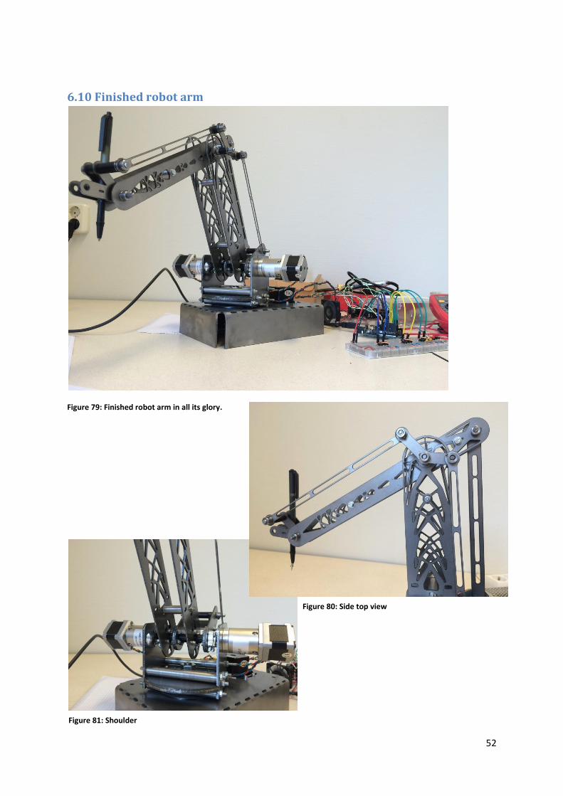
52
6.10 Finished robot arm
Figure 79: Finished robot arm in all its glory.
Figure 80: Side top view
Figure 81: Shoulder

53
Figure 82: Rear view
Figure 83: lower arm push system
Figure 84:Side left view
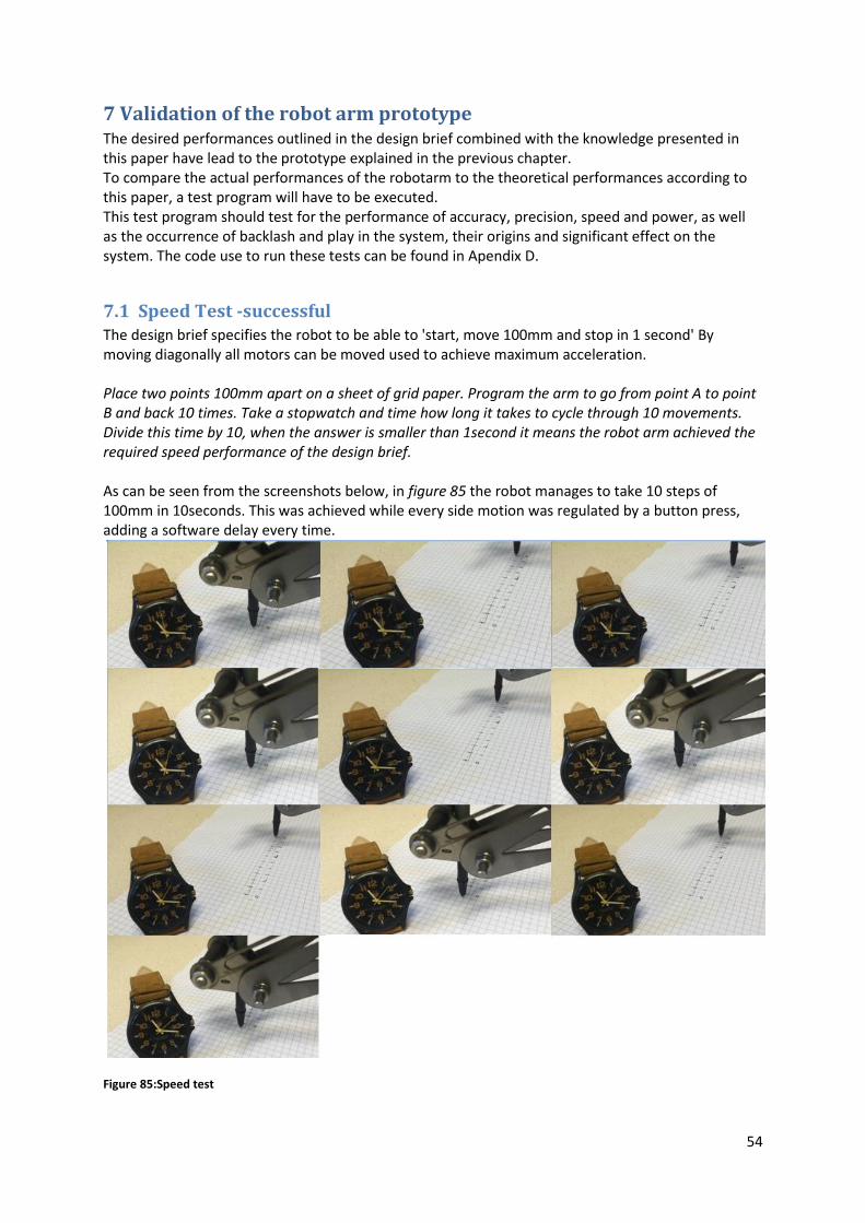
54
7 Validation of the robot arm prototype The desired performances outlined in the design brief combined with the knowledge presented in this paper have lead to the prototype explained in the previous chapter. To compare the actual performances of the robotarm to the theoretical performances according to this paper, a test program will have to be executed. This test program should test for the performance of accuracy, precision, speed and power, as well as the occurrence of backlash and play in the system, their origins and significant effect on the system. The code use to run these tests can be found in Apendix D.
7.1 Speed Test -successful The design brief specifies the robot to be able to 'start, move 100mm and stop in 1 second' By moving diagonally all motors can be moved used to achieve maximum acceleration. Place two points 100mm apart on a sheet of grid paper. Program the arm to go from point A to point B and back 10 times. Take a stopwatch and time how long it takes to cycle through 10 movements. Divide this time by 10, when the answer is smaller than 1second it means the robot arm achieved the required speed performance of the design brief. As can be seen from the screenshots below, in figure 85 the robot manages to take 10 steps of 100mm in 10seconds. This was achieved while every side motion was regulated by a button press, adding a software delay every time.
Figure 85:Speed test

55
7.2 Power Test -successful The requirement for power is that the robot arm should be able to lift a load of 500g with a stretched arm. According to the specifications of the manufacturer the motors in the prototype arm are rated to 4Nm after the gearbox. To lift 500g at a fully stretched arm of 40cm roughly 2Nm is needed. The motors should be well within its power reach to lift the specified load. Connect a bottle of water to the end effector of the robot arm. Fill the bottle with 100mL water, lift it up 5cm and bring it down again. Adjust the potmeter on the driver board of the steppermotors to increase the current output if necessary. Add 100mL water to the bottle and lift it up again. Continue adding water in steps of 100mL and testing the motors until 500mL (500gram) is reached. If the robot arm can lift a bottle of 500mL the power performance is reached. The power test was also successfully completed. While the arm is stretched out fully it was capable of lifting the fully filled 0.5L water bottle, see figure 86, weighing slightly more than 0.5L. The arm was also able to lift the bottle without any problems.
7.3 Accuracy Test - successful The design brief specifies an accuracy of 2mm, this is the same accuracy as the commercial desktop robot arm do-bot. Calculate and program 5 locations as targets for the robotic arm. Let the program run through 5
cycles of touching each point in a different order. Calculate the average location deviation at each
point. The maximum average location deviation of these points can be seen as amount of inaccuracy.
Figure 88: Accuracy and precison results
Figure 86: 0.5Kg lift test
Figure 87: Location areas up close

56
The accuracy of the arm is the average deviation from where the end effector is to where it should actually be. The pen used in this test was a fine liner, which can place dots with a diameter of 0.6mm. The result of the accuracy test can be seen in figure 87 &88. At every target there are 5 dots, this may be hard to tell from the photos since some of the dots overlap. The program ran through the programmed locations forward two times, than backwards two times followed by forward one more time. The accuracy at each point is as follows;
Position 0:
Position 1:
Position 2:
Position 3:
Position 4: Position 5: Average Accuracy The reason for the high inaccuracy at position 2 is, as is visible in the video, that the paper was slightly bulged upwards, causing the pen coming in at an angle to start marking the paper before it was at the programmed destination. The repeated deviation of 1.5 and 1.8mm at positions 0 and 1 are most likely due to backlash in the belt and pulley system driven by the hip motor.
7.4 Precision Test -successful The precision can also be tested by attaching a pen to the endeffector of the arm, programming
multiple destination points, having the arm cycle through these multiple times and measure the
maximum distances between individual dots. Imprecision may not be greater than 2mm, as specified
in the design brief.
The same method and results are used to determine precision as were used to determine accuracy.
Results of this test can be seen in figure 87 & 88 Position0: 1.5mm Position1: 1.5mm Position2: 2mm Position3: 1mm Position4: 0.2mm Position5: 0mm The precision at position 2 is the maximum allowed limit. The reason for this measurement is, as is visible in the video, that the paper was slightly bulged upwards, causing the pen coming in at an angle to start marking the paper before it was at the programmed destination. With this in mind, the precision is 1,5mm.

57
7.5 Backlash and play There will exist play in the system due to the backlash, bearings, fixtures or other unforeseen factors. It is important to analyse where it originates from and how they affect the system. Use the same 5 locations program and let the robot cycle through the point in both directions. Check if there are structural and predictable deviations. Wiggle the end effector to see if there is play in the system and locate the origin. Do this above line paper to see how much play is in the system. During testing for precision and accuracy it became clear that there is some backlash in the system due to the belt and pulley system. When approaching locations 0 and 1 from different angles there was a structural deviation of 1.5mm. Extra testing confirmed the existence of backlash, when the robot arm rotated left to right multiple times in a row, it repeatedly landed on the same spots, when the arm rotated two times to the left and then right it misses the destination by about 1.5mm. By moving the endeffector up and it reveals the backlash caused by the shoulder and elbow motor. When the robot is in operation, the motors constantly provide torque in the same direction to keep the arm from falling down. This backlash only occurs when the pressing down of the endeffector is desired. Play is also present in the system. When the endeffector is at the maximum reach it can be forced sideways to displace 3mm, when released the endeffector springs back to the neutral position. The endeffector can also be moved to both sides for 0.5mm without springing back to the neutral position. This play originates visibly at the elbow joint and is most likely caused by the tolerance of the fit where the lower arm is fitted on the elbow axis.
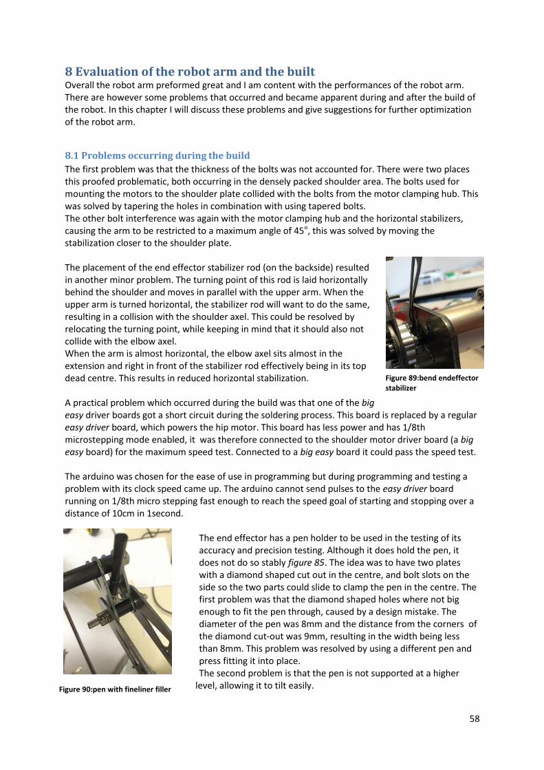
58
8 Evaluation of the robot arm and the built Overall the robot arm preformed great and I am content with the performances of the robot arm. There are however some problems that occurred and became apparent during and after the build of the robot. In this chapter I will discuss these problems and give suggestions for further optimization of the robot arm.
8.1 Problems occurring during the build
The first problem was that the thickness of the bolts was not accounted for. There were two places this proofed problematic, both occurring in the densely packed shoulder area. The bolts used for mounting the motors to the shoulder plate collided with the bolts from the motor clamping hub. This was solved by tapering the holes in combination with using tapered bolts. The other bolt interference was again with the motor clamping hub and the horizontal stabilizers, causing the arm to be restricted to a maximum angle of 45o, this was solved by moving the stabilization closer to the shoulder plate. The placement of the end effector stabilizer rod (on the backside) resulted in another minor problem. The turning point of this rod is laid horizontally behind the shoulder and moves in parallel with the upper arm. When the upper arm is turned horizontal, the stabilizer rod will want to do the same, resulting in a collision with the shoulder axel. This could be resolved by relocating the turning point, while keeping in mind that it should also not collide with the elbow axel. When the arm is almost horizontal, the elbow axel sits almost in the extension and right in front of the stabilizer rod effectively being in its top dead centre. This results in reduced horizontal stabilization. A practical problem which occurred during the build was that one of the big easy driver boards got a short circuit during the soldering process. This board is replaced by a regular easy driver board, which powers the hip motor. This board has less power and has 1/8th microstepping mode enabled, it was therefore connected to the shoulder motor driver board (a big easy board) for the maximum speed test. Connected to a big easy board it could pass the speed test. The arduino was chosen for the ease of use in programming but during programming and testing a problem with its clock speed came up. The arduino cannot send pulses to the easy driver board running on 1/8th micro stepping fast enough to reach the speed goal of starting and stopping over a distance of 10cm in 1second.
The end effector has a pen holder to be used in the testing of its accuracy and precision testing. Although it does hold the pen, it does not do so stably figure 85. The idea was to have two plates with a diamond shaped cut out in the centre, and bolt slots on the side so the two parts could slide to clamp the pen in the centre. The first problem was that the diamond shaped holes where not big enough to fit the pen through, caused by a design mistake. The diameter of the pen was 8mm and the distance from the corners of the diamond cut-out was 9mm, resulting in the width being less than 8mm. This problem was resolved by using a different pen and press fitting it into place. The second problem is that the pen is not supported at a higher
level, allowing it to tilt easily.
Figure 89:bend endeffector stabilizer
Figure 90:pen with fineliner filler

59
8.2 Recommendations
The first recommendation of improvement on this prototype would be the end effector. At the moment this is a ball point pen top, with the insides of a fine-liner pen wedged inside, being held into place because the pen was forced in figure 85. When redesigning a pen holding endeffector it should be noted that the pen should be kept stable at different heights to keep it from tilting. Another recommendation is a rotation stopper to keep the robot arm from turning more than 180o in both directions. The way the arm is setup now, it could rotate too far and pull the wires out of the driver boards or the motors. This could be resolved by adding a stopping plate to the basis and the rotating shoulder assembly. To get more use out of the robotic arm it may be necessary to swap out the arduino for a more advanced micro controller with a higher clock speed. That way it is possible to drive all motors at once without losing speed. Another problem that should be addressed is the end effector stabilizer rod system. The way the stabilizer is installed now results in it reaching its top dead centre when the arm is fully stretched and losing much of the stabilizing ability. To make full use of the robot arm, the motors should be able to run at the same time. By doing this the robot could draw shapes, laser engrave or 3D print. It is possible to do this with this setup by having a better programmer or team of programmers and an upgrade to the arduino.
60
9 Evaluation of the paper and models The purpose of this paper was to analyse the different components that go into making a robotic arm, how they work and how they influence the performance of the entire system. While at the same time making a model to predict and relate desired performances to required components, their composition and their cost and also to explore the possibilities for designing and producing high quality robotic arms at the right cost. The information required to build the prototype arm can all be found in this paper, like the type of frame structure to use, the types of bearings and the types of motors best suited. This lead to the successful build of a robotic arm. The purpose of analysing the different components, how and why they work and their influence on the performance of the robot arm was therefore successful. The model presented in this paper to calculate the required motor torque was put to the test and proved to be correct. This paper also presented a model to predict the precision of a robot arm, based on the worst case scenario for play in bearings, motor resolution, backlash and frame deflection. The model predicted the worst case imprecision's to be 1.59mm while the real precision was 1.5mm. These results seem to prove the model to be true for this test. However, the model does not include the imprecision's caused by the tolerances in the fit of the lower arm on the elbow axel and the upper arm on the shoulder axel. Were these to be included, the prediction would be higher and the real precision would still be within the boundaries.

61
Sources General information: Motors: baldor.com SERVO CONTROL FACTS, A HANDBOOK EXPLAINING THE BASICS OF MOTION solarbotics.net Industrial Circuits Application Note, Stepper Motor Basics bimba.com, Guajardo G., A BIMBA Whitepaper, Stepper vs. Servo: Which is Better Served with My Electric Cylinder? micromo.com, a member of the FAULHABER GROUP, Stepper Motor Technical Note: Microstepping Myths and Realities http://blog.misumiusa.com The great debate: Stepper or Servo? Bearings: mit.edu FUNdaMENTALS of Design, Topic10, Bearings Timing belts sdp-si.com HANDBOOK OF TIMING BELTS AND PULLEYS lasersaur.com T-3 THE WORLD OF TIMING BELTS Figures: 1: sainsmart.com DIY 4-Axis Servos Control Palletizing Robot Arm Model for Arduino UNO MEGA2560 2: robotshop.com Lynxmotion AL5D 4DOF Robotic Arm SSC-32U Combo Kit 3 123rf.com Very high resolution 3d rendering of an industrial robot 4 crustcrawler.com AX-18A Smart Robotic Arm 5: machinedesign.com The Difference between Cartesian, Six-Axis, and SCARA Robots 6: aaltomies.wordpress.com Mecha design: Basic hinge joints 7: sainsmart.com DIY 4-Axis Servos Control Palletizing Robot Arm Model for Arduino UNO MEGA2560 8: reset.etsii.upm.es/en/projects/robotic-arm/ Robotic Arm 9: https://en.wikipedia.org/wiki/Accuracy_and_precision 10: antarcticglaciers.org Precision and accuracy in glacial geology 11: servocity.com How Does a Servo Work 12: www.pololu.com Continuous-rotation servos and multi-turn servos 13: wikipedia.org Stepper motor 14: wikipedia.org Stepper motor 15: servocity.com How Does a Servo Work 16: servocity.com How Does a Servo Work 17: micromo, a member of the FAULHABER GROUP, Stepper Motor Technical Note: Microstepping Myths and Realities 18: micromo, a member of the FAULHABER GROUP, Stepper Motor Technical Note: Microstepping Myths and Realities 19: wikipedia.org Flexure bearing 20: automotioncomponents.co.uk R4002 Flexure Pivot Bearings 21: ofbusiness.com SKF India Deep Groove Ball Bearings 6312-2Z/C3 22: zx55.com SKF Energy Efficient (E2) Deep Groove Ball Bearings 23: engineerlive.com Needle roller bearings: 60 years and still evolving 24: hkdivedi.com BALL BEARING BASICS AND TYPES 25: en.ofweek.com Thrust Cylindrical Roller Bearing Series 89xxx 26: skf.com Angular contact ball bearings 27: skf.com Tapered roller bearing 28: directindustry.com Tapered roller bearing / double-row / for heavy loads 29: directindustry.com Spherical roller thrust bearing 30: skf.com Spherical roller thrust bearings

62
31: jktbearings.com Self Aligning Ball bearings 32: jktbearings.com Self Aligning Ball bearings 33: lrservicekits.com Gates 'PowerGrip' Timing Belt Kit for Range Rover Evoque 2.2D 34: .scribd.com T-3 THE WORLD OF TIMING BELTS 35: scribd.com T-3 THE WORLD OF TIMING BELTS 36: scribd.com T-3 THE WORLD OF TIMING BELTS 37: scribd.com T-3 THE WORLD OF TIMING BELTS 38: inventables.com belt-what-type-is-standard-on-x-carve 39: scribd.com T-3 THE WORLD OF TIMING BELTS 41: ab.com Encoders 42: ab.com Encoders 43: wikipedia.org Backlash (engineering) 47: automotioncomponents.co.uk R2084 Spur Gears 48: gizmocnc.com Brass anti-backlash ACME nut 1/2-10 46: reset.etsii.upm.es/en/projects/robotic-arm/ Robotic Arm 67: omc-stepperonline.com Gear Ratio 51:1 Planetary Gearbox With Nema 14 Stepper Motor 14HS13-0804S-PG51 68: omc-stepperonline.com 0.9deg Nema 17 Bipolar Stepper Motor 2A 46Ncm 17HM19-2004S 71: sparkfun.com Big easy driver Tables 1: Wohlers Report: Additive Manufacturing Industry Surpassed $5.1 Billion. (2016, June 1). Appliance Design


![On Writing [expressing a relation to] Dried Plant Specimens · On Writing [expressing a relation to] Dried Plant Specimens ... the planet against degradation and loss. ... enquiry,”](https://static.fdocuments.us/doc/165x107/5af27a967f8b9a8c308fd1f2/on-writing-expressing-a-relation-to-dried-plant-writing-expressing-a-relation.jpg)