An Empirical Investigation of SSDL - Soya - Soya
161
An Empirical Investigation of SSDL Patric Fornasier School of Computer Science and Engineering, University of New South Wales, Australia [email protected] A thesis submitted in partial fulfilment of the requirements for the degree of: Master of Science in Computer Science & Engineering Sydney, October 27, 2007
Transcript of An Empirical Investigation of SSDL - Soya - Soya
An Empirical Investigation of SSDL
Patric Fornasier
School of Computer Science and Engineering, University of New South Wales, [email protected]
A thesis submitted in partial fulfilment of the requirements for the degree of:
Master of Science in
Computer Science & Engineering
Sydney, October 27, 2007


An Empirical Investigation of SSDL
Patric Fornasier
School of Computer Science and Engineering, University of New South Wales, [email protected]
A thesis submitted in partial fulfilment of the requirements for the degree of:
Master of Science in
Computer Science & Engineering


Abstract
The SOAP Service Description Language (SSDL) is a SOAP-centric languagefor describing Web Service contracts. SSDL focuses on message abstraction asthe building block for creating service-oriented applications and provides an ex-tensible range of protocol frameworks that can be used to describe and formallymodel Web Service interactions. SSDL’s natural alignment with service-orienteddesign principles intuitively suggests that it encourages the creation of applica-tions that adhere to this architectural paradigm. Given the lack of tools andempirical data for using SSDL as part of Web Services-based SOAs, we identi-fied the need to investigate its practicability and usefulness through empiricalwork. To that end we have developed Soya, a programming model and run-time environment for creating and executing SSDL-based Web Services. On theone hand, Soya provides straightforward programming abstractions that fos-ter message-oriented thinking. On the other hand, it leverages contemporarytooling (i.e. Windows Communication Foundation) with SSDL-related runtimefunctionality and semantics. In this thesis, we describe the design and architec-ture of Soya and show how it makes it possible to use SSDL as an alternativeand powerful metadata language without imposing unrealistic burdens on ap-plication developers. In addition, we use Soya and SSDL in a case study whichprovides a set of initial empirical results with respect to SSDL’s strengths anddrawbacks. In summary, our work serves as a knowledge framework for betterunderstanding message-oriented Web Service development and demonstratesSSDL’s practicability in terms of implementation and usability.
iii


Originality Statement
“I hereby declare that this submission is my own work and to the best of myknowledge it contains no materials previously published or written by anotherperson, or substantial proportions of material which have been accepted forthe award of any other degree or diploma at UNSW or any other educationalinstitution, except where due acknowledgement is made in the thesis. Anycontribution made to the research by others, with whom I have worked at UNSWor elsewhere, is explicitly acknowledged in the thesis. I also declare that theintellectual content of this thesis is the product of my own work, except to theextent that assistance from others in the project’s design and conception or instyle, presentation and linguistic expression is acknowledged.”
Signed . . . . . . . . . . . . . . . . . . . . . . . . . . . . . . . . . .
Date . . . . . . . . . . . . . . . . . . . . . . . . . . . . . . . . . .
v

Copyright Statement
“I hereby grant the University of New South Wales or its agents the right toarchive and to make available my thesis or dissertation in whole or part in theUniversity libraries in all forms of media, now or here after known, subject tothe provisions of the Copyright Act 1968. I retain all proprietary rights, suchas patent rights. I also retain the right to use in future works (such as articlesor books) all or part of this thesis or dissertation.
I also authorise University Microfilms to use the 350 word abstract of my thesisin Dissertation Abstract International.
I have either used no substantial portions of copyright material in my thesis orI have obtained permission to use copyright material; where permission has notbeen granted I have applied/will apply for a partial restriction of the digitalcopy of my thesis or dissertation.”
Signed . . . . . . . . . . . . . . . . . . . . . . . . . . . . . . . . . .
Date . . . . . . . . . . . . . . . . . . . . . . . . . . . . . . . . . .
vii

Authenticity Statement
“I certify that the Library deposit digital copy is a direct equivalent of the finalofficially approved version of my thesis. No emendation of content has occurredand if there are any minor variations in formatting, they are the result of theconversion to digital format.”
Signed . . . . . . . . . . . . . . . . . . . . . . . . . . . . . . . . . .
Date . . . . . . . . . . . . . . . . . . . . . . . . . . . . . . . . . .
ix


Publications
Parts of this work have been published in the following conference proceedings:
P. Fornasier, and J. Webber, and I. Gorton, “Soya: a programming model andruntime environment for component composition using ssdl,” in Component-Based Software Engineering, pp. 227–241, Springer Berlin / Heidelberg, 2007.
xi


Acknowledgements
Very rarely is the successful completion of a project the achievement of one per-son alone. Indeed, this work would not have been possible without the supportof faculty members, colleagues, fellow students, family, partner and many dearfriends all over the world.
In particular, I would like to thank my supervisors Prof. Ian Gorton and Prof.Ross Jeffrey as well as my co-supervisors Dr. Liming Zhu and Dr. Helen Paikfor guiding me through my studies and providing me with valuable feedbackand continuous advice.
I am also deeply grateful to Dr. Jim Webber for his commitment and active in-volvement in my work. His advice on various levels and many lively discussionshave been extremely encouraging and have significantly contributed to this work.
In addition, I want to express my gratitude to the following three organisationsfor offering me their trust and generous support: the National ICT Australia(NICTA), which is funded through the Australian Government’s Backing Aus-tralia’s Ability initiative, in part through the Australian Research Council; theHasler Foundation, which is a Swiss non-profit organisation that promotes re-search and training in the field of telecommunications, distributed informationsystems and related topics; and ABB Switzerland, a multinational company,which provides power and automation technologies and supports young engi-neers in pursuing further education.
Thank You All!
xiii


Contents
Abstract iii
Originality Statement v
Copyright Statement vii
Authenticity Statement ix
Publications xi
Acknowledgements xiii
List of Figures xx
List of Tables xxi
1 Introduction 11.1 Thesis Focus and Contribution . . . . . . . . . . . . . . . . . . . 21.2 Thesis Structure . . . . . . . . . . . . . . . . . . . . . . . . . . . 4
2 Background 52.1 RPC and Distributed Object Technologies . . . . . . . . . . . . . 5
2.1.1 Shortcomings . . . . . . . . . . . . . . . . . . . . . . . . . 62.2 Messaging . . . . . . . . . . . . . . . . . . . . . . . . . . . . . . . 8
2.2.1 Asynchronous Calls . . . . . . . . . . . . . . . . . . . . . 92.2.2 Message-Oriented Middleware (MOM) . . . . . . . . . . . 102.2.3 Message Brokers . . . . . . . . . . . . . . . . . . . . . . . 10
2.3 Service-Oriented Architecture (SOA) . . . . . . . . . . . . . . . . 122.3.1 The Four Tenets of Service Orientation . . . . . . . . . . 13
2.4 REpresentational State Transfer (REST) . . . . . . . . . . . . . . 142.4.1 Rationale . . . . . . . . . . . . . . . . . . . . . . . . . . . 152.4.2 Uniform Interfaces . . . . . . . . . . . . . . . . . . . . . . 152.4.3 Messages and Data Representations . . . . . . . . . . . . 162.4.4 Resources or Services? . . . . . . . . . . . . . . . . . . . . 16
2.5 MESsage Transfer (MEST) . . . . . . . . . . . . . . . . . . . . . 172.5.1 One-Way Messages and Interaction Protocols . . . . . . . 172.5.2 Logical Operation . . . . . . . . . . . . . . . . . . . . . . 17
2.6 Web Services . . . . . . . . . . . . . . . . . . . . . . . . . . . . . 172.6.1 Defining Web Services . . . . . . . . . . . . . . . . . . . . 18
xv
2.6.2 Do we need Web Services? . . . . . . . . . . . . . . . . . . 202.6.3 Web Services Architecture . . . . . . . . . . . . . . . . . . 212.6.4 SOAP . . . . . . . . . . . . . . . . . . . . . . . . . . . . . 232.6.5 Interaction Styles . . . . . . . . . . . . . . . . . . . . . . . 252.6.6 Web Services Description Language (WSDL) . . . . . . . 28
2.7 Interaction Protocols . . . . . . . . . . . . . . . . . . . . . . . . . 292.7.1 Protocol Languages . . . . . . . . . . . . . . . . . . . . . 31
2.8 Service Composition and Workflows . . . . . . . . . . . . . . . . 332.8.1 Relationship with Interaction Protocols . . . . . . . . . . 332.8.2 Business Process Execution Language (BPEL) . . . . . . 34
2.9 SOAP Service Description Language (SSDL) . . . . . . . . . . . 352.9.1 Structure . . . . . . . . . . . . . . . . . . . . . . . . . . . 352.9.2 Messages . . . . . . . . . . . . . . . . . . . . . . . . . . . 362.9.3 Protocols . . . . . . . . . . . . . . . . . . . . . . . . . . . 372.9.4 Claimed Benefits . . . . . . . . . . . . . . . . . . . . . . . 382.9.5 Tool Support . . . . . . . . . . . . . . . . . . . . . . . . . 39
2.10 Summary . . . . . . . . . . . . . . . . . . . . . . . . . . . . . . . 39
3 The Programming Model 413.1 Development Life Cycle . . . . . . . . . . . . . . . . . . . . . . . 413.2 Defining SSDL Contracts Using Metadata . . . . . . . . . . . . . 42
3.2.1 Defining Messages . . . . . . . . . . . . . . . . . . . . . . 433.2.2 Defining Messaging Behaviour . . . . . . . . . . . . . . . 45
3.3 Implementing a Service . . . . . . . . . . . . . . . . . . . . . . . 473.4 Client API . . . . . . . . . . . . . . . . . . . . . . . . . . . . . . 47
3.4.1 Initiating a Conversation . . . . . . . . . . . . . . . . . . 483.4.2 Replying to a Previous Message . . . . . . . . . . . . . . . 48
3.5 Configuring a Service . . . . . . . . . . . . . . . . . . . . . . . . . 493.6 Client-Server Symmetry . . . . . . . . . . . . . . . . . . . . . . . 50
3.6.1 XML Firewalls . . . . . . . . . . . . . . . . . . . . . . . . 523.7 Service Deployment . . . . . . . . . . . . . . . . . . . . . . . . . 52
4 The Runtime Environment 554.1 Introduction . . . . . . . . . . . . . . . . . . . . . . . . . . . . . . 554.2 Runtime Components . . . . . . . . . . . . . . . . . . . . . . . . 56
4.2.1 Processing Flow . . . . . . . . . . . . . . . . . . . . . . . 574.3 Message Correlation & State Maintenance . . . . . . . . . . . . . 57
4.3.1 Leveraging WS-Addressing . . . . . . . . . . . . . . . . . 594.3.2 Session Context Management . . . . . . . . . . . . . . . . 594.3.3 Session Context Lifetime and Maintenance . . . . . . . . 614.3.4 Synchronisation of Session Context Access . . . . . . . . . 62
4.4 Structural Validation . . . . . . . . . . . . . . . . . . . . . . . . . 634.5 Protocol Validation . . . . . . . . . . . . . . . . . . . . . . . . . . 63
4.5.1 Dynamic State Pattern . . . . . . . . . . . . . . . . . . . 654.5.2 Usage . . . . . . . . . . . . . . . . . . . . . . . . . . . . . 664.5.3 Implementation . . . . . . . . . . . . . . . . . . . . . . . . 674.5.4 Decorating the State Machine . . . . . . . . . . . . . . . . 684.5.5 Non-Determinism and Ambiguity . . . . . . . . . . . . . . 684.5.6 Persisting State and Cloning . . . . . . . . . . . . . . . . 70
4.6 Message Dispatching . . . . . . . . . . . . . . . . . . . . . . . . . 71
xvi

4.6.1 State-Based Method Selection . . . . . . . . . . . . . . . . 714.6.2 Asynchronous Operation Invocation . . . . . . . . . . . . 72
4.7 Metadata Generation and Exposure . . . . . . . . . . . . . . . . 754.8 Building the Runtime . . . . . . . . . . . . . . . . . . . . . . . . 75
4.8.1 Building the Internal Service Model . . . . . . . . . . . . 774.8.2 Building the Protocol State Machine . . . . . . . . . . . . 77
5 Case Study 795.1 Motivation and Background . . . . . . . . . . . . . . . . . . . . . 79
5.1.1 Lending Industry XML Initiative (LIXI) . . . . . . . . . . 805.1.2 Property Valuation Process . . . . . . . . . . . . . . . . . 80
5.2 Approach . . . . . . . . . . . . . . . . . . . . . . . . . . . . . . . 815.3 Case One: Property Valuation . . . . . . . . . . . . . . . . . . . 82
5.3.1 Focus . . . . . . . . . . . . . . . . . . . . . . . . . . . . . 825.3.2 Case Description . . . . . . . . . . . . . . . . . . . . . . . 825.3.3 Protocol Translation . . . . . . . . . . . . . . . . . . . . . 845.3.4 Development Process . . . . . . . . . . . . . . . . . . . . . 865.3.5 Discussion . . . . . . . . . . . . . . . . . . . . . . . . . . . 90
5.4 Case Two: Intermediary . . . . . . . . . . . . . . . . . . . . . . . 935.4.1 Focus . . . . . . . . . . . . . . . . . . . . . . . . . . . . . 935.4.2 Case Description . . . . . . . . . . . . . . . . . . . . . . . 935.4.3 Sequencing Constraints . . . . . . . . . . . . . . . . . . . 955.4.4 Discussion . . . . . . . . . . . . . . . . . . . . . . . . . . . 995.4.5 Comparison with WSDL & BPEL . . . . . . . . . . . . . 1015.4.6 Discussion . . . . . . . . . . . . . . . . . . . . . . . . . . . 105
5.5 Conclusion . . . . . . . . . . . . . . . . . . . . . . . . . . . . . . 107
6 Discussion 1096.1 State Machine Expression Power . . . . . . . . . . . . . . . . . . 1096.2 State Maintenance using WS-Addressing . . . . . . . . . . . . . . 110
6.2.1 Uniqueness of MessageID . . . . . . . . . . . . . . . . . . 1106.2.2 Multi-Party Conversations . . . . . . . . . . . . . . . . . . 111
6.3 Defining Protocols using Attributes . . . . . . . . . . . . . . . . . 1126.4 SOAP Action Semantics . . . . . . . . . . . . . . . . . . . . . . . 1126.5 WSDL Operations . . . . . . . . . . . . . . . . . . . . . . . . . . 1126.6 Asynchronous Interaction Model . . . . . . . . . . . . . . . . . . 1136.7 Assuming SOAP Only . . . . . . . . . . . . . . . . . . . . . . . . 1136.8 Content-Based Message Dispatching . . . . . . . . . . . . . . . . 1146.9 SSDL Faults . . . . . . . . . . . . . . . . . . . . . . . . . . . . . . 115
6.9.1 Fault XML Schema . . . . . . . . . . . . . . . . . . . . . 116
7 Conclusions 1197.1 Summary of Work Undertaken . . . . . . . . . . . . . . . . . . . 1207.2 Summary of Findings . . . . . . . . . . . . . . . . . . . . . . . . 1217.3 Directions for Future Work . . . . . . . . . . . . . . . . . . . . . 122
Bibliography 123
Appendices 133
xvii


List of Figures
2.1 Synchronous and Asynchronous Interaction Semantics . . . . . . 92.2 Messaging System . . . . . . . . . . . . . . . . . . . . . . . . . . 102.3 Message Broker . . . . . . . . . . . . . . . . . . . . . . . . . . . . 112.4 Basic SOA . . . . . . . . . . . . . . . . . . . . . . . . . . . . . . . 132.5 MEST Architecture . . . . . . . . . . . . . . . . . . . . . . . . . 182.6 Web Service as XML Processor . . . . . . . . . . . . . . . . . . . 192.7 First Generation Web Services Architecture . . . . . . . . . . . . 212.8 WS-* Architecture . . . . . . . . . . . . . . . . . . . . . . . . . . 222.9 Web Service Engagement . . . . . . . . . . . . . . . . . . . . . . 242.10 Simple SOAP Message . . . . . . . . . . . . . . . . . . . . . . . . 242.11 Difference: Protocols – Workflows . . . . . . . . . . . . . . . . . . 342.12 SSDL Structure . . . . . . . . . . . . . . . . . . . . . . . . . . . . 362.13 SSDL Message Definition . . . . . . . . . . . . . . . . . . . . . . 372.14 MEP Protocol . . . . . . . . . . . . . . . . . . . . . . . . . . . . 382.15 SC Protocol . . . . . . . . . . . . . . . . . . . . . . . . . . . . . . 38
3.1 Typical SSDL Service Implementation . . . . . . . . . . . . . . . 423.2 Inferring SSDL Contract from Service Implementation . . . . . . 433.3 SSDL Contract . . . . . . . . . . . . . . . . . . . . . . . . . . . . 513.4 XML Firewall . . . . . . . . . . . . . . . . . . . . . . . . . . . . . 52
4.1 Soya Middleware Layer . . . . . . . . . . . . . . . . . . . . . . . . 564.2 Soya System . . . . . . . . . . . . . . . . . . . . . . . . . . . . . . 564.3 Soya Runtime Architecture . . . . . . . . . . . . . . . . . . . . . 584.4 Scalability . . . . . . . . . . . . . . . . . . . . . . . . . . . . . . . 594.5 Session Context Creation and Access . . . . . . . . . . . . . . . . 604.6 Session Context Synchronisation . . . . . . . . . . . . . . . . . . 624.7 MEP State Machines . . . . . . . . . . . . . . . . . . . . . . . . . 644.8 Combined MEP State Machine . . . . . . . . . . . . . . . . . . . 654.9 TCP Connection . . . . . . . . . . . . . . . . . . . . . . . . . . . 654.10 Dynamic State Pattern . . . . . . . . . . . . . . . . . . . . . . . . 664.11 IExtensibleObject<T> Pattern . . . . . . . . . . . . . . . . . . . 684.12 State Machine Decoration . . . . . . . . . . . . . . . . . . . . . . 694.13 Deterministic, Ambiguous Service . . . . . . . . . . . . . . . . . . 694.14 Unambiguous Service . . . . . . . . . . . . . . . . . . . . . . . . . 704.15 Non-Deterministic, Unambiguous Service . . . . . . . . . . . . . 704.16 State-Based Method Selection . . . . . . . . . . . . . . . . . . . . 724.17 Asynchronous Invocation . . . . . . . . . . . . . . . . . . . . . . 744.18 Metadata Retrieval . . . . . . . . . . . . . . . . . . . . . . . . . . 75
xix

4.19 Building the Runtime . . . . . . . . . . . . . . . . . . . . . . . . 764.20 Protocol (In)Dependent Model Creation . . . . . . . . . . . . . . 774.21 Building the Protocol State Machine . . . . . . . . . . . . . . . . 78
5.1 Valuation Lifecycle . . . . . . . . . . . . . . . . . . . . . . . . . . 815.2 Valuation Conversation . . . . . . . . . . . . . . . . . . . . . . . 835.3 Valuation Protocol . . . . . . . . . . . . . . . . . . . . . . . . . . 845.4 MEP Protocol . . . . . . . . . . . . . . . . . . . . . . . . . . . . 855.5 Protocol Comparison: Business – MEP . . . . . . . . . . . . . . . 855.6 Requestor Contract in C# . . . . . . . . . . . . . . . . . . . . . . 885.7 Interactive Console . . . . . . . . . . . . . . . . . . . . . . . . . . 905.8 Valuation Conversation including Intermediary . . . . . . . . . . 945.9 Intermediary Protocol . . . . . . . . . . . . . . . . . . . . . . . . 955.10 SC Protocol using Multiple Semantics . . . . . . . . . . . . . . . 965.11 Iteration in SC Protocol . . . . . . . . . . . . . . . . . . . . . . . 975.12 SC Protocol: Intermediary – Valuation Firm . . . . . . . . . . . 985.13 SC Protocol: Intermediary . . . . . . . . . . . . . . . . . . . . . . 985.14 Intermediary Contract in C# . . . . . . . . . . . . . . . . . . . . 1025.15 BPEL Partner Links . . . . . . . . . . . . . . . . . . . . . . . . . 102
xx
List of Tables
2.1 Formal Models Comparison . . . . . . . . . . . . . . . . . . . . . 32
5.1 LIXI Terminology . . . . . . . . . . . . . . . . . . . . . . . . . . 805.2 Message Exchange Patterns . . . . . . . . . . . . . . . . . . . . . 845.3 Number of Lines of Code Comparison . . . . . . . . . . . . . . . 107
xxi


Chapter 1
Introduction
} I find that the harder I work, the more luck I seem to have. ~
— Thomas Jefferson
Complex software systems are often constructed according to simpler and morecomprehensible abstract models and guidelines. One architectural style thathas garnered recent attention is service-oriented architecture (SOA) [1]. SOAis a named set of coordinated architectural constraints that can guide softwaredevelopers during the creation of large-scale distributed software systems. Fun-damentally, SOA follows the common practice of decomposing a complex prob-lem into smaller, independent and thus more manageable abstractions. In anSOA, these abstractions are autonomous units of logic called services. Servicesuse messages to communicate and exchange structured information among eachother while descriptions capture the form and patterns of how these interactionscan take place. Together, services, messages, and descriptions form the threemain components of a basic SOA [2].
Although service-orientation per se is neither a new nor a technology-depen-dent paradigm, the advent and emergence of Web Services has reinvigoratedinterest in the approach [3]. Indeed, Web Services offer a suitable technologyplatform for realising service-oriented applications. By defining a set of stan-dards and models, they enable the integration of independent, heterogeneouscomponents and make it possible to create a new class of interesting distributedapplications. Simply using Web Services, however, does not automatically leadto service-oriented design [4]. As a matter of fact, Web Services technology canlikewise be used to create applications that adhere to other architectural princi-ples which are less suitable for building Internet-scale applications. The designof WSDL [5], for example, is procedure call-centric and can constrain Web Ser-vices practitioners from adopting a more message-oriented mindset. Its focus on
1

2 CHAPTER 1. INTRODUCTION
operations as the primary abstraction for communication has resulted in a largenumber of tools (e.g. [6, 7]), which generate code that shields network communi-cation in order to make remote service invocations look like local method calls.Web Service applications built in such ways are consequently not architecturallydifferent from RPC systems [8]. In other words, these systems are often tightlycoupled, brittle at distribution boundaries and limited in scalability [9].
In contrast, then, the SOAP Service Description Language (SSDL) [10] is anXML-based language that describes Web Services in a message-oriented way. Inits crudest form, it can be seen as a direct language replacement for WSDL. Yetunlike the latter, SSDL focuses on one-way SOAP messages [11], not operations,as the building blocks for creating service-oriented applications. Moreover, itprovides mechanisms, known as protocol frameworks, which can be used to com-bine messages into interaction protocols that define their expected relative or-dering and thus enable protocol-based reasoning. In general, the message-centricconcepts underlying SSDL provide a more natural fit with service-oriented de-sign principles than the operation-centric design of languages like WSDL. Intu-itively, this suggests that SSDL inherently fosters the creation of loosely coupledand scalable applications.
1.1 Thesis Focus and Contribution
Currently, virtually no data exists on experiences in implementing tool supportfor SSDL or using the same as part of Web Services-based SOAs. Consequently,this raises a number of questions that this study seeks to answer. At one endof the spectrum, it is unclear if the approach proposed by SSDL is truly prac-ticable. In other words, can sensible programming abstractions and runtimesupport be provided that aid developers in building service-oriented applica-tions without adding unrealistic development burdens. At the other end, wecan only speculate if SSDL indeed has significant benefits compared to the in-cumbent approaches that exist for describing Web Services (e.g. in terms offostering service-orientation, reducing complexity, increasing semantic expres-siveness, etc.).
Unfortunately, SSDL has not been widely adopted by the community. Wespeculate that the main inhibitors to SSDL being adopted more widely is thegeneral lack of engagement by leading Web Services technology companies suchas IBM, Microsoft, Oracle, Bea etc. and the absence of tool support for creat-ing and executing SSDL-based Web Services. There are neither tools nor pro-gramming abstractions available that could assist developers in modelling andimplementing SSDL-based Web Services. Furthermore, no SSDL-aware run-time platform exists, which is needed to realise the benefits of SSDL’s machine-

1.1. THESIS FOCUS AND CONTRIBUTION 3
processable message and protocol descriptions.
To that end we have developed Soya [12], a programming model and run-time environment for creating and executing SSDL-based Web Services. Thedevelopment of Soya presented us with a number of non-trivial research andengineering challenges, which we discuss in this thesis. In summary, Soya pro-poses to address problems in the following areas of SSDL-based Web Servicedevelopment:
• programming abstractions: the efficient creation of SSDL Web Services ne-cessitates straightforward programming abstractions that foster the lan-guage’s underlying message-oriented practices. Most developers are fa-miliar with synchronous method call semantics only. SSDL’s interactionmodel, however, is asynchronous. The programming model must thereforedeal with this dilemma by providing abstractions that are easily adoptable,even by developers who are not accustomed to working with asynchronousinteractions. In addition, it needs to provide mechanisms for capturingcontractual information (e.g. XML schema, message descriptions, proto-cols, etc.) without adding unrealistic development effort;
• runtime support : an SSDL engine should exhibit the same features thatare commonly found in contemporary SOAP-processing middleware (e.g.efficient processing of SOAP messages, support of prevalent Web Servicesstandards such as security or reliability, etc.). In addition, it must obvi-ously provide functionality and semantics related to SSDL. This includesmessage validation in terms of structure and ordering, state maintenanceby means of WS-Addressing [13], protocol-based message dispatching andso forth. Finally, the runtime architecture must take SSDL’s extensibleprotocol framework mechanism into account and ideally be independentof the programming abstraction in use.
The main contributions of this work to the field of software research arethe design and implementation of a programming model and runtime environ-ment for creating and executing SSDL-based Web Services, respectively. Byproviding the community with this knowledge and infrastructure, we hope topromote message-oriented Web Services design and motivate further researchin this direction. In order to validate the usability of Soya’s programming ab-stractions and the proper functioning of its runtime, we apply it to a case studyin connection with the Australian lending industry. In addition to demonstrat-ing its practicability, this research is important because it provides an initialset of empirical results that differentiate Soya and SSDL from the prevalentapproaches.

4 CHAPTER 1. INTRODUCTION
1.2 Thesis Structure
Chapter 2 provides an extensive and critical overview of relevant literature to ar-ticulate the problem field to which this work applies. We follow a chronologicalperspective of different architectural styles and practices for creating distributedsoftware applications. In particular, we emphasise Web Services technology as aplatform for building service-oriented applications. We also introduce concepts,models and languages from the domain of protocol and workflow research. Weconclude the chapter with a presentation and discussion of SSDL. In Chap-ters 3 and 4 we give an in-depth presentation of Soya’s programming modeland runtime environment, respectively. These constitute the original empiricalwork of the thesis. First, we elaborate on how Soya helps developers to modelSSDL-based Web Services. Then, we follow with a detailed explanation of howthe various runtime components work. Chapter 5 presents a case study in thecreation of a service-oriented system in connection with the Australian lendingindustry. We show how the system can be realised with the aid of Soya andSSDL. Additionally, we re-model the application using incumbent approachesand compare the results. In Chapter 6 we discuss remaining open issues, whichhad not been addressed in previous chapters. Chapter 7 concludes the thesisby summarising the findings and contributions of our work and indicating somedirections for future research.

Chapter 2
Background
} The task is not so much to see what no one yet has seen,but to think what nobody yet has thought,
about that which everybody sees. ~
— Arthur Schopenhauer
Over the years, architectural styles and best practices for creating software haveevolved and changed many times. This has required software engineers to con-tinuously adapt both technology and mindset. At the same time, the largenumber of existing paradigms, principles, tools and so forth can also be confus-ing or even deceptive. In this chapter, we discuss some relevant architecturalstyles and technologies and their implications in terms of creating Web Serviceapplications. Although this comprises a review of existing relevant literature, itholds conceptual originality. Specifically, it produces the framework and ratio-nale on which we built Soya.
2.1 RPC and Distributed Object Technologies
In 1976, James E. White from the Standford Research Institute published anRFC1 containing details about what he called the “procedure call model” [8].The ideas described in his original RFC 707 became later known as remoteprocedure calls (RPC). White’s intention was to abstract and hide networkcomplexity in order to provide an environment that looked familiar to softwaredevelopers who were used to writing non-distributed applications. In the late1970s, RPC replaced client-server database connection designs. In the 1990s,RPC technologies such as CORBA [14] and DCOM [15] emerged, which pro-vided a complete distributed system architecture. Upon the arrival of the World
1RFC stands for “Request for Comments”
5
6 CHAPTER 2. BACKGROUND
Wide Web in the mid-to-late 1990s, Internet technology was incorporated intodistributed architectures and custom client components were often replaced withbrowsers. In these architectures, proprietary RPC protocols were consequentlyreplaced by HTTP [16]. Some years after, Java followed with its object equiva-lent of RPC called Remote Method Invocation (RMI) [17] and later EnterpriseJava Beans (EJB) technology [18], which likewise provided significant additionsto the original RPC. Internally, these components communicated via propri-etary APIs while still using one or the other form of RPC for communicatingacross program boundaries.
All these technologies promised to make developers’ lives easier by hidingtedious network communication code and making remote objects look like lo-cal objects, in accordance with White’s original ideas. This was achieved bygenerating intermediary proxy and stub classes that shielded and handled thenetwork communication. During proxy generation, the expected interactions be-tween components were taken into account by statically embedding referencesamong each other into the proxy code. Even though many software projectshave successfully applied RPC-based technologies over the last two decades,these technologies have a range of shortcomings. As a matter of fact, it hasbeen known for several years that RPC is not ideal for Internet-wide computing(e.g. [19, 20, 21, 22]).
2.1.1 Shortcomings
2.1.1.1 Programming Model
Back in 1994, Waldo et al. suggested that “objects that interact in a distributedsystem need to be dealt with in ways that are intrinsically different from ob-jects that interact in a single address space”2. According to the authors, thevision of unified objects cannot be successfully applied to large distributed sys-tems because it tries to conceal fundamental dissimilarities between local andremote communication. This includes differences in network latency, memoryaddress space, concurrency and partial failure scenarios. Consequently, Waldoet al. suggested that calls across a network must be clearly distinguished andtreated differently from local calls within the same address space [9]. Yet RPCprogramming abstractions conceal these dissimilarities, and do thus not allowdevelopers to differentiate between them.
2Waldo et al., “A note on distributed computing”, 1994

2.1. RPC AND DISTRIBUTED OBJECT TECHNOLOGIES 7
2.1.1.2 Interface Complexity
RPC-based applications tend to be tightly coupled and thus limited in scala-bility. Their components often expose a large number of complex, fine-grainedand diverse interfaces that mirror implemented procedures or object structures.Also, components are connected in a point-to-point fashion, resulting in manydependencies among each other. As the number of application components in-creases, the number of possible connections grows exponentially. As a result,keeping track of the semantics of each component’s interface becomes increas-ingly difficult as Vinoski notes in [23]. In practice, making changes to interfacescan be virtually impossible, as it may imply updating a large number of depen-dent components; all the more, if components are scattered across organisationalor trust boundaries. Fowler remarks in [21] that these problems are often notsignificant within single n-tier applications but become so when different inde-pendent applications are integrated.
2.1.1.3 Synchronous Communication
Despite its many advantages, synchronous communication has also a number ofdrawbacks, in particular when used in highly distributed environments. Syn-chronous communication is not well suited for long-running activities, becauseclients keep connections open while waiting for results. As a consequence, serversneed to maintain large numbers of concurrent connections, which affects boththeir performance and complexity. Further, synchronous calls make componentsdependent on the availability of others. In a distributed environment, such asthe Internet, where it is a reality that network links fail or applications becomeunavailable, this can disrupt the entire application.
2.1.1.4 Enterprise Application Integration (EAI)
RPC couples applications further in terms of middleware technology that needsto be the same on both ends of communicating components. Still, we men-tioned above that many applications have been built successfully with RPCtechnologies. These achievements, however, were mostly limited to environ-ments characterised by platform homogeneity and predictable latencies, such asthe corporate Internet [20]. Yet in order to create truly large-scale applicationsthat span organisational, trust and geographical boundaries, where networks arelatent, message loss is common, transmission speed varies and so forth, RPC isnot an apt technology. Hohpe and Woolf sum it up accurately in [21] by sayingthat while RPC could be used to distribute n-tier applications, it is not suitablefor integrating independent applications.

8 CHAPTER 2. BACKGROUND
2.2 Messaging
Messaging is an architectural style in which independent applications commu-nicate with each other remotely by exchanging structured data called messages.Based on the message content, the receiving application performs appropriateactions and potentially sends new messages back. Because the applications in-teract in an asynchronous manner, they are inherently loosely-coupled3, moredynamic and more reliable.
In message-oriented systems, the lines between client and server (or senderand receiver, producer and consumer, etc.) are blurred. Both sides can freelysend and receive messages in either direction and their roles can thus changeduring the course of a single conversation. The distinction is purely conceptualand only makes sense in connection with the semantics of the message exchange.
Besides enabling remote communication, messaging systems can overcomeplatform and language issues by providing universal communication interfacesfor different technologies. Additionally, asynchronous communication can im-prove performance because the sender of a message does not need to wait for thereceiver to process it. Instead, it can perform other work and therefore increaseits throughput. Finally, messaging interactions are more reliable than standardRPC. If, for example, the network link or the receiver is not working properly,a messaging system tries to resend the message until it succeeds. Hohpe andWoolf give a more extensive list and a description of the advantages providedby messaging in [21].
As a result, messaging has been the favourite approach for integrating au-tonomous and heterogeneous applications into large-scale enterprise systems fora number of years [3, 24]. In fact, messaging solutions have been successfullyapplied in a wide range of domains including the financial sector, which is knownfor its high performance and reliability requirements. The Society for World-wide Interbank Financial Telecommunications (SWIFT), for example, processedmore than 2 billion messages per year during 2003 [25].
Although asynchronous messaging architectures are powerful, they also in-troduce new challenges. One of them is the significant differences in the designapproaches that are associated with asynchronism. Because developers are nor-mally familiar with synchronous method-call semantics, the idioms and pecu-liarities of asynchronous communication requires working with a more complexevent-driven programming model. Further, there are issues relating to messageordering and synchronisation. Again, an extensive description of the challengesintroduced by asynchronous messaging is given by Hohpe and Woolf in [21].
3The fewer assumptions two applications need to make about each other in order to ex-change information, the less coupled they are.

2.2. MESSAGING 9
2.2.1 Asynchronous Calls
Interactions in software systems are often characterised in terms of blocking(synchronous) or non-blocking (asynchronous) behaviour. In a synchronousinteraction, a process calling a sub-process blocks and must wait for the responsefrom the sub-process before it can proceed. Synchronous calls also block whenthe called process executes in an independent, possibly remote environment.In an asynchronous interaction, conversely, the calling process does not needto wait for a response and can proceed while the sub-process executes. Thisdifference in semantics is illustrated in Figure 2.1.
Blocking
Process A
Process Bcall return
blocked
time
Non-Blocking
Process A
Process Bcall
time
Figure 2.1: Comparison between synchronous and asynchronous interaction se-mantics. Adapted from [21].
Asynchronous communication decouples processes and can improve perfor-mance. However, it is generally more complex because processes run concur-rently and their exact execution sequence can no longer be determined. Addi-tionally, results of an asynchronous call must be communicated to the callingprocess somehow (e.g. via a callback or shared variables) and then be associatedcorrectly with the context in which the call was made.
Undeniably, synchronous behaviour has advantages in terms of simplicityand makes perfect sense in many situations, such as invoking operations onlocal objects. However, we have reasoned earlier that communication across anetwork is fundamentally different from interactions among objects in the sameaddress space. Abstracting the former into the simple semantics of local methodcalls can thus be deceptive. Synchronous communication among distributedapplications couples them in a tight manner. As a result, applications integratedin this fashion have more complex dependencies and are harder to maintain. Incontrast, applications that communicate by means of asynchronous messageexchange can operate more independently of each other. Consequently, theintegrated application components will be more loosely coupled.

10 CHAPTER 2. BACKGROUND
2.2.2 Message-Oriented Middleware (MOM)
The systems that provide messaging capabilities are known as Message-OrientedMiddleware (MOM) (e.g. [26, 27, 28]). These systems coordinate and managethe sending and receiving of messages between applications, which are connectedusing virtual pipes called message channels.
MOM systems normally connect applications in a point-to-point fashion,where a sender places a message into a queue. Normally this is done in a non-blocking fashion. Then, the middleware moves the message from the senderto the receiver, which extracts it from the other end of the queue and startsprocessing it. If the receiver is not available, the system retries the deliveryuntil it succeeds. The receiver can obtain the message in either a blockingor a non-blocking fashion; by either waiting for a new message or providing acallback function that is invoked when a new message arrives. This process isillustrated in Figure 2.2.
Sender
Message Channel
Receiver
Messaging System
Figure 2.2: A messaging system that connects two components through a mes-sage channel. Adapted from [21].
Unfortunately, the point-to-point model requires communicating applica-tions to be directly connected with each other. This design is thus relativelystatic and inflexible. Further, the number of connections (i.e. queues) growsexponentially with the number of integrated applications. Because of its manyconnections between applications, this kind of design is often referred to asspaghetti architecture.
2.2.3 Message Brokers
Message brokers address the limitations of basic MOM systems by extendingthem with centralised message routing, filtering and processing capabilities. Abroker thus basically acts as a Mediator [29] between the integrated applications.For example, the publish-subscribe messaging model, which is supported by vir-tually every message broker, enables many-to-many communication over onechannel. Essentially, the publish-subscribe paradigm has the same underlying

2.2. MESSAGING 11
principle that is described by the Observer pattern in [29]. Subscriber applica-tions can subscribe to topics, which are basically logically named queues. Whena new message is published to a topic, the middleware notifies each subscribedapplication by sending it a copy of the message.
Additionally, message brokers can centralise message content transforma-tions. As a result, heterogeneous applications can send messages in their ownformat, which are then transformed by the broker into a unified format.
By introducing a message broker, the complexity and number of communi-cation interfaces in the endpoints is reduced to a great extent. Figure 2.3 showsan architecture with a message broker that is often referred to as a hub andspoke model, because of its similarity to a bicycle wheel.
Message Broker
Figure 2.3: Using a message broker reduces complexity between applications atintegration points. Adapted from [24].
Although a lot of the complexity is captured in a central place and messagebroker products normally include powerful tools to describe routing or transfor-mation logic the approach still has a number of drawbacks. First and foremost,the spaghetti architecture still exists inside the broker as visible in Figure 2.3.Second, placing application logic into the broker can make applications moredifficult to debug and maintain. Third, brokers are potential performance bot-tlenecks, because all messages flow through a central point.
Despite their benefits and success in corporate Intranets, MOM systems arenot ideal for Internet-wide application integration. On one side, homogeneousmiddleware platforms are required to connect applications. On the other side,the middleware needs to be placed – as the name suggests – “in the middle”of the integrated applications. When applications exceed organisational bound-aries, this often causes practical problems, the solutions to which aren’t only ofa technical nature. It is very likely that companies do not have the same kind

12 CHAPTER 2. BACKGROUND
of MOM systems and are not able or willing to change them. Further, it raisessecurity issues, as one company needs to access another companies middlewareinfrastructure.
2.3 Service-Oriented Architecture (SOA)
Service-oriented architecture (SOA) [1] is a recent architectural style whichguides software architects during the creation of large-scale distributed soft-ware systems4. Although the fundamentals underlying SOA are not at all newand some even claim that they are as old as trade and the commercial mar-ketplace itself [1], the emergence of Web Services technology has clearly rein-vigorated interest in service-oriented principles. Nevertheless, SOA per se is atechnology-agnostic paradigm and can potentially also be realised using otherimplementation strategies. Indeed, Sprott and Wilkes [30] claim that distributedarchitectures were early attempts to realise SOAs and that the notion of serviceis an integral part of component thinking.
A lot has been written about SOA but often with a strong inclination towardsWeb Services technology (e.g. [31, 32, 2, 33]). A more puristic attempt todefine a common language and understanding of SOA independent of technologywas realised by the Organisation for the Advancement of Structured Standards(OASIS), which defines SOA as follows:
“Service Oriented Architecture (SOA) is a paradigm for organisingand utilising distributed capabilities that may be under the control ofdifferent ownership domains.”5
Fundamentally, SOA follows the common practice of decomposing a complexproblem into smaller, independent, more manageable abstractions. In an SOA,these independent and autonomous units of logic are called services. Servicesare higher-level abstractions that provide capabilities which other services canuse without knowledge of how they were provided. Services use messages tocommunicate and exchange structured information among each other while de-scriptions capture the form and patterns of how these interactions take place.Together, services, messages, and descriptions form the building blocks of abasic SOA [2].
4It has been argued that the naming of SOA is unfortunate because discussions relatingto it often involve areas such as business design or delivery processes, which exceed the scopeof architecture. Some authors have thus suggested to use the term Service Orientation (SO)instead [30]. On account of its widespread use in the field of software architecture and be-cause this thesis focuses on software development, we will nevertheless use the three-letternomenclature.
5OASIS, “Reference model for service oriented architecture v 1.0”, Section 2.1, 2006
2.3. SERVICE-ORIENTED ARCHITECTURE (SOA) 13
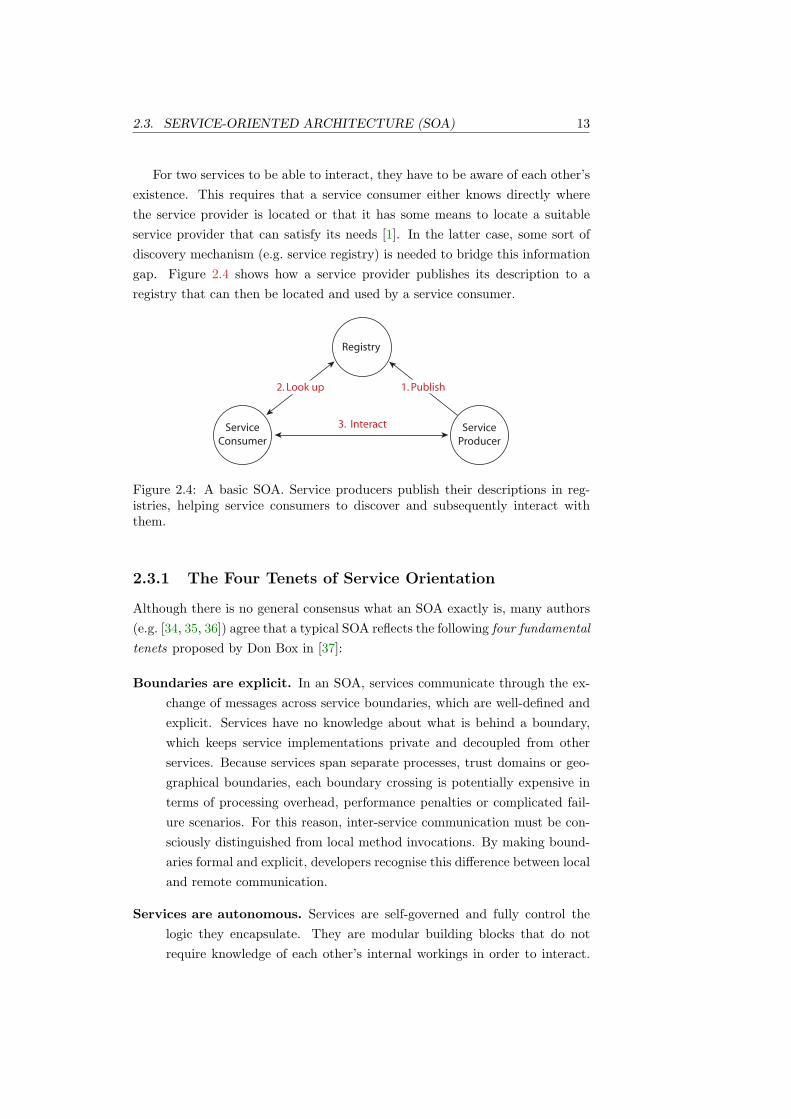
For two services to be able to interact, they have to be aware of each other’sexistence. This requires that a service consumer either knows directly wherethe service provider is located or that it has some means to locate a suitableservice provider that can satisfy its needs [1]. In the latter case, some sort ofdiscovery mechanism (e.g. service registry) is needed to bridge this informationgap. Figure 2.4 shows how a service provider publishes its description to aregistry that can then be located and used by a service consumer.
Registry
Service
Consumer
Service
Producer
1. Publish2. Look up
Interact3.
Figure 2.4: A basic SOA. Service producers publish their descriptions in reg-istries, helping service consumers to discover and subsequently interact withthem.
2.3.1 The Four Tenets of Service Orientation
Although there is no general consensus what an SOA exactly is, many authors(e.g. [34, 35, 36]) agree that a typical SOA reflects the following four fundamentaltenets proposed by Don Box in [37]:
Boundaries are explicit. In an SOA, services communicate through the ex-change of messages across service boundaries, which are well-defined andexplicit. Services have no knowledge about what is behind a boundary,which keeps service implementations private and decoupled from otherservices. Because services span separate processes, trust domains or geo-graphical boundaries, each boundary crossing is potentially expensive interms of processing overhead, performance penalties or complicated fail-ure scenarios. For this reason, inter-service communication must be con-sciously distinguished from local method invocations. By making bound-aries formal and explicit, developers recognise this difference between localand remote communication.
Services are autonomous. Services are self-governed and fully control thelogic they encapsulate. They are modular building blocks that do notrequire knowledge of each other’s internal workings in order to interact.

14 CHAPTER 2. BACKGROUND
As a result, services can evolve independently from each other as long asthey do not alter their public contracts. Moreover, as the topology of aservice-oriented system is expected to change over time, adding, upgradingor removing services should not disrupt the overall system.
Services share schemas and contracts, not classes. Services maintain im-plementation independence by exposing only schemas and contracts thatare expressed in a platform-neutral format. Schemas define the struc-ture of messages a service can receive or send, while contracts determinethe mechanics of these interactions. Together, schemas and contracts areshared beyond service boundaries.
In [38], Helland premises that data residing inside services is actually dif-ferent from data residing outside services in many essential points. Heargues that the only way these boundaries can be crossed is by means ofmessages carrying outside data to the inside or vice versa and that afterreceiving or before sending messages it lies within a service’s responsibil-ity to cope with the necessary transitions. He concludes that differenttechnologies (e.g. SQL and object-oriented languages for inside data andXML [39] for outside data) must be used to allow for the different char-acteristics that apply to inside and outside data.
Compatibility is determined based on policy. Besides using schemas andcontracts for agreeing on structural compatibility in terms of messagesand exchange sequences, services might have further constraints on thesemantics required for communication to take place. Therefore, both re-quirements and capabilities are expressed in a machine-readable policydescription. This separates the description of a service’s behaviour fromthe specification of constraints for accessing it.
Despite ongoing and often nearly religious debates about architectural styles(e.g. REST vs. SOA [40]), it has been widely accepted that SOA provides aflexible and useful approach to manage the complexity that arises when devel-oping large-scale distributed software systems (e.g. [31, 35, 34, 41, 42]). For thisreason, we are not investigating SOA further at this point but will resume thetopic to some extent later in conjunction with our discussion on Web Servicesin Section 2.6.
2.4 REpresentational State Transfer (REST)
REpresentational State Transfer (REST) is an architectural style for describingdistributed hypermedia systems such as the World Wide Web. Indeed, REST

2.4. REPRESENTATIONAL STATE TRANSFER (REST) 15
was developed as an abstract model of the Web architecture, or more preciselya model of how the Web should work [43]. The term was coined by Fielding inhis doctoral thesis in 2000 [44], just shortly after the first Web Services-relatedwork had started6. The fact alone that the largest distributed software system,the World Wide Web, is built in a RESTful way, justifies mentioning REST inthis thesis. Yet we are particularly interested in REST because many argue thatthe principles it advocates can and should likewise be applied to Web Servicearchitectures. As a matter of fact, there have been ongoing debates splitting theWeb Services community into different camps. One side advocates the creationof Web Services based on REST concepts using mainly HTTP and XML. Theother side maintains that Web Services should be implemented using SOA andthe WS stack (i.e. SOAP and other WS-* protocols) [40].
2.4.1 Rationale
REST defines a set of architectural constraints that are intended to increaseperformance and scalability of distributed hypermedia systems. In REST, theworld is perceived as a collection of resources which are each named with aunique identifier (e.g. a URI [46]). Interactions occur between clients and serversin a pull-based style and involve exchanging representations of resources at agiven state (i.e. state transfer). In the case of the World Wide Web, a clientcould, for example, send a HTTP GET request to a server, which in turn sendsback a representation of the resource expressed in HTML. Of course, the resourcecould also be represented as XML, as a picture, as plain text and so forth. Everyresource is accessed through a uniform interface that defines a fixed set of verbs(e.g. GET, PUT, UPDATE, DELETE), which allow clients to interact with it.Other REST constraints require that servers are stateless, content is cacheable,components can be layered and so forth.
2.4.2 Uniform Interfaces
RESTful applications work with uniform interfaces. In contrast, RPC-orientedsystems, including most current Web Service architectures, tend to have spe-cialised verbs for each interface or service, respectively. As we have seen inSection 2.1.1.2, complex interfaces have been a major obstacle for creating scal-able distributed applications in the past. In REST this issue does not existbecause all interfaces are described with a fixed number of verbs. As a re-sult, RESTful applications must focus more on the exchanged messages. Notsurprisingly, REST promotes the notion of self-describing messages [44].
6Box et al. released SOAP 1.0 in November 1999 [45].

16 CHAPTER 2. BACKGROUND
Although most of today’s Web Services expose specialised and diverse op-erations, there are also some Web Service practitioners that advocate a moreRESTful approach to Web Service interfaces. The MEST architectural style,described in the next section, for example, constrains Web Services to only onelogical operation, which effectively eliminates interface complexity.
2.4.3 Messages and Data Representations
Despite the fact that interfaces in RESTful architectures are uniform, the datawhich is exchanged between them remains variable. Messages can contain datain different standardised formats that are specified within the message itself. InHTTP, for example, the content-type header can be used to inform the client inwhat format the data inside the message is represented. Since many formats arestandardised and supported by most web browsers, they can easily be displayedor processed.
2.4.4 Resources or Services?
Clearly, Web Services have been successfully designed using either a RESTful ora service-oriented approach and it is, in fact, unclear if one approach is generallybetter than the other. Vinoski discusses differences between the two schools ofthought to some extent in [40], but without coming to a decision that wouldclearly favour one over the other. Zur Muehlen et al. did a comparison in thecontext of choreography [47]. Although they used a superseded version of SOAPand chose an RPC interaction model (see Section 2.6.5.1), their paper similarlydid not seem to reflect a distinct inclination towards either approach.
Amazon.com, for example, provides both REST and SOAP interfaces toaccess their Web Services [48]. Remarkably, 85% of developers in this exampleare apparently using the REST interface, whereas only 15% are interactingwith the service using SOAP [49]. The high percentage of REST interface usersin Amazon’s statistics, however, might be due to the fact that browser-basedclients are a fairly natural way in which to interact with their Web Services.
The fact that the World Wide Web works is a solid argument that RESTprinciples are sound for creating at least certain types of distributed systems.Yet we are not aware of the existence of RESTful Web Service applicationsthat implement some of the more advanced features Web Services can provide,such as transferring messages via intermediary nodes and different transportprotocols. Also, Web Service applications are normally not implemented ashypermedia systems. Time, more research and further practical work will tellif one of the two approaches is indeed more suitable.

2.5. MESSAGE TRANSFER (MEST) 17
2.5 MESsage Transfer (MEST)
MESsage Transfer (MEST) is an architectural style that views distributed ap-plications only in terms of messages that are transferred between services. Theoriginal authors of MEST claim that it “is for service-orientation and Web Ser-vices what REST is for resource-orientation and the Web” [50]. Despite the pun,MEST is actually not very similar to REST. In terms of commonalities, bothstyles particularly advocate uniform component interfaces and self-describingmessages.
2.5.1 One-Way Messages and Interaction Protocols
In MEST, interactions between services are purely modelled as one-way mes-sages that are exchanged among services in a loose and asynchronous manner.Using one-way messages as the fundamental building blocks, they can be com-bined into simple patterns and sophisticated interaction protocols that describethe interaction behaviour of applications (see Section 2.7). MEST perceivesmessages as independent, self-contained units of information that do not con-vey details of underlying APIs or transport protocols. Accordingly, it expectsapplications to reason and act solely based on message’s content.
2.5.2 Logical Operation
Recognising that many developers are familiar with the semantics of operationabstractions, MEST provides the concept of a logical asynchronous operationcalled ProcessMessage(). However, this does not mean that services actu-ally implement this method. The notion is purely conceptual and should beperceived as a way to help convey the basic concepts underlying service com-munication. In fact, the semantics associated with executing this method isequivalent to the transfer of a message to a service combined with the implicitrequest to process it. Of course, the realisation of the message transfer changeswith respect to the underlying transport level (e.g. HTTP POST, FTP PUT,TCP send/recv, SMTP DATA). Yet this does not affect the higher-level ab-stractions used in MEST. Figure 2.5 illustrates this view graphically.
2.6 Web Services
The focus of this thesis is to investigate SSDL – a language for describing WebServices. Consequently, the latter form the conceptual framework to whichthis research applies. A lot has been written about Web Service concepts andtechnology in the past few years (e.g. [51, 52, 3, 53, 54, 2]). Rather than giving

18 CHAPTER 2. BACKGROUND
Figure 2.5: Services communicate with each other in a loose and asynchronousmanner by exchanging one-way messages. This is abstracted by invoking a singlelogical operation that is uniformly present on all services (rectangles).
an exhaustive overview of Web Services, we focus only on the aspects mostrelevant to our work.
2.6.1 Defining Web Services
At the end of 2004, the World Wide Web Consortium’s (W3C) Web ServicesArchitecture working group (WSAWG) produced a note on Web Services ar-chitecture [4]. The document identifies and abstracts characteristics commonto most Web Service applications and explains their relationships among eachother in general terms. Moreover, it provides a definition of what a Web Serviceis and a common vocabulary about Web Service concepts.
Rather than using the W3C’s definition of Web Service7, however, we willuse our own definition, as it reflects our personal view more aptly:
“A Web Service is a software system designed to support interop-erable machine-to-machine interaction. This is achieved throughexchanging messages over an arbitrary number of network and ap-plication protocols. Normally, a Web Service exposes a machine-processable contract that captures the mechanics of how other sys-tems can interoperate with it.”
2.6.1.1 Web Services are XML Processors
In [20], Vogels proposes that Web Services can be viewed as XML processorsthat send and receive XML documents over a combination of transport andapplication protocols. This view is illustrated in Figure 2.6. Upon receiving amessage, the Web Service processes it, executes some application logic based
7W3C, “Web services architecture”, Section 1.4, 2004

2.6. WEB SERVICES 19
on the message content and possibly constructs a new message, which it dropsback onto the network.
Message Processing
Application Logic
Resources
Web Service
Figure 2.6: Web Service seen as an XML message processors. Adapted from [34].
In fact, this behaviour is quite similar to how businesses or people commu-nicate in the real world. Imagine a company C1 that wants to order some itemsfrom another company C2. To do so, C1 fills out an order form (i.e. message)with the order details (i.e. message content) and posts, faxes or emails (i.e.transport protocol) it to C2. C2 in turn receives and reads the message (i.e.message processing) and forwards the order request to an internal departmentin order to deal with it (i.e. application logic). Unfortunately, the departmentrealises that it is currently out of stock and thus writes a letter back to C1,saying that it is currently unable to deliver the requested items. C1 receives theletter, reads it and so forth.
2.6.1.2 Web Services are Interoperability Standards
Note that in the above example, there are no notions like operations, invocations,interfaces, etc. All the actions are performed solely based on the informationcontained in the message. Of course, there are some implied semantics thatcorrespond to the ones above and we need to make sure, for example, that theother party understands our request. Writing a letter in Japanese to an Italiancompany might not lead to the expected result. Likewise, sending an orderfor semiconductor parts to a clothing warehouse would probably not yield thedesired result. In a similar way, Web Services need to ensure that exchangedmessages are mutually understood. For this reason, Web Services technologydefines open standards that enable different heterogeneous applications to in-teroperate. During the last few years, Web Services have matured into a com-

20 CHAPTER 2. BACKGROUND
moditised platform and it is widely believed that they can significantly advanceworldwide interoperable distributed computing [20].
2.6.1.3 Web Services enable SOA
Although we said earlier that SOA is an implementation-agnostic paradigm,Web Services have received wide acceptance as a technology for realising SOAs.The Web Services framework provides standards and models that are conceptu-ally aligned with SOA. This includes the abstract notion of service in additionto specifications relating to service description and discovery, messaging, servicecomposition, quality of service (QoS) and so forth.
Yet as reasoned earlier and noted by the W3C in [4], using Web Servicestechnology alone does not imply that any given software architecture will mag-ically become service-oriented. Wrapping and exposing application objects asWeb Services, for example, is a practice commonly promoted by many toolk-its. In [41], Vinoski discusses some of the problems that are associated withthis approach, including semantic mismatches, data type mapping and statemanagement issues, limitations in scalability, performance and so forth.
2.6.2 Do we need Web Services?
Many technologies have been applied successfully in creating distributed sys-tems and integrating applications. Yet all of them have always posed restric-tions on their environment (e.g. low latency networks, homogeneous platforms,etc.) [20, 3]. This prevented them from achieving the ubiquity that the WorldWide Web has. Web Services are another step in the evolution of distributedsystems engineering and are hoped and believed to enable interoperability andapplication integration on a global scale.
Conventional middleware such as MOM or RPC (see Section 2.2 and Sec-tion 2.1) limits large-scale integration across organisational, trust or geograph-ical boundaries for several reasons. MOM approaches integrate existing ap-plications through a central point of access. This inevitably raises logistical,political, confidentiality and other issues that hinder the practicability of thisapproach. RPC-style integration efforts, on the other hand, integrate applica-tions directly in a point-to-point fashion. This implies that connected partiesindividually agree on a common infrastructure, data format, protocol, etc. Inpractice, however, different parties might want to use diverse protocols, formatsand infrastructure (e.g. corporate policy, existing infrastructure, political mo-tivations, etc.). This results in the creation of hard-to-maintain heterogeneoussystems in addition to the issues discussed in Section 2.1 and Section 2.2.
Web Services aim to solve these problems by providing open interoperability

2.6. WEB SERVICES 21
standards, which enable application composition and integration irrespective ofunderlying technology, implementations and platforms. As a result, applica-tions can be created that transcend organisational or geographical boundaries,network protocols and component heterogeneity.
2.6.3 Web Services Architecture
2.6.3.1 First Generation Web Services
The Web Service architecture is based on a set of standards and specificationsthat provide a framework to build interoperable applications on top of existingnetwork protocols. The standards are notably based on XML in order to achieveplatform and language independence8. According to several sources (e.g. [51, 53,32]), the early Web Service architecture consisted of three main specifications.They were SOAP [11], the Web Services Description Language (WSDL) [5]and the Universal Description, Discovery, and Integration (UDDI) directory.SOAP provided the semantics for communication, WSDL defined a vocabularyto describe the capabilities of a Web Service in a machine-processable format andUDDI specified how to publish and discover information about Web Services.Figure 2.7 shows how the three specifications relate. Note that this architectureis congruent with the basic SOA we defined in Section 2.3.
UDDI
WS WS
1. Publish WSDL2. Look up WSDL
3. SOAP
Figure 2.7: First generation Web Services architecture.
2.6.3.2 WS-*
Today, the relationship between these basic specifications is commonly known asfirst generation Web Services architecture [32]. This architecture had a numberof limitations and did not cover more advanced topics such as security, reliablemessaging, transactions, service orchestration and so forth [55]. These issueswere addressed in subsequent iterations by additional specifications that are
8As a matter of fact, many refer to XML as the lingua franca of Web Services.

22 CHAPTER 2. BACKGROUND
often collectively referred to as WS-* [56]. Figure 2.8 depicts the key WS-*specifications and their interrelationships in a schematic way.
TransportTCP, UDP, HTTP, FTP, SMTP, JMS...
TransferSOAP
CompositionWS-BPEL
ManagementWS-Management,
WS-ResourceTransfer
Met
aD
ata
WS
DL
, W
S-P
oli
cy,
WS
-Me
taD
ata
Exc
ha
ng
e,
WS
DL
-S, U
DD
I, W
S-C
DL
...
Sec
uri
tyW
S-S
ecu
rity
, WS
-Se
cCo
nv,
WS
-Tru
st,
WS
-Fe
de
rati
on
, WS
-Se
curi
tyP
oli
cy.
..
Tra
nsa
ctio
ns
WS
-Co
ord
ina
tio
n, W
S-B
usi
ne
ssA
cti
vit
y,
WS
-Ato
mic
Tra
nsa
cti
on
MessagingWS-Addressing, MTOM, WS-Enumeration,
WS-Eventing, WS-Transfer...R
elia
bili
tyW
S-R
eli
ab
leM
ess
ag
ing
Ses
sio
ns
WS
-Co
nte
xt
Figure 2.8: Schematic overview of the WS-* architecture. The transport layer isnot actually part of the WS-* specifications, but nevertheless shown for clarity.Adapted from [55, 56]
The number of specifications is large and not all of them have been im-plemented or have become actual industry standards. Also, because specifica-tions have been written by different authors (i.e. companies), various standardsco-exist that address similar problem domains. Vinoski discusses this prob-lem in [57], observing that no specification standardisation has yet occurredand that the vast number of (often overlapping) specifications can be confusing(e.g. [58, 59]). This is aggravated by the fact that no clear common guidelinesexist that could help the community in implementing Web Service systems.Although the W3C has produced a note on Web Services architecture [4], itdescribes only some architectural areas and not how the WS-* specifications fitinto the overall architecture – mainly because the notes predates most of theWS-* specifications.

2.6. WEB SERVICES 23
2.6.3.3 Web Service Concepts and Engagement
Still, the W3C note [4] defines characteristics common to most Web Serviceapplications at an abstract level. This includes the identification of importantconcepts and how they relate to each other. One of them is the general processof how two Web Services engage in a conversation, illustrated in Figure 2.9. Wewill use this example in the following paragraph to explain some fundamentalconcepts.
Because Web Services can be both clients and servers in the traditionalsense, we normally use these terms more out of convenience than correctness.For that reason, two interacting Web Services are more accurately referred toas requestors and providers. Interaction is typically facilitated through someagent (e.g. software built on middleware such as Axis [6], XFire [60], WCF [61],etc.). Before interaction occurs, however, the two parties need to agree on thesemantics and mechanics of the subsequent interaction. This information isused to configure, build or generate agents that know how to interact with eachother. Some of this information is typically captured in machine-processabledocuments such as WSDL descriptions [5] or WS-Policy files [62]. Other in-formation, however, might not be of machine-processable, explicit or writtennature but merely exist in an implicit, oral or human-oriented form. Clearly,it is desirable to have machine-processable Web Services descriptions that aresemantically rich enough to capture every aspect of service-level agreement andinteroperation in order to enable full automation. Over the last few years,languages and specifications have emerged that aim to describe the mechan-ics of message exchange more accurately as part of Web Service descriptions(e.g. [63, 64, 10]). Other approaches go even further and try to infuse differenttypes of semantics (e.g. data, functional, non-functional, execution) into WebServices (e.g. [65, 66]). Still, the results of this early research have not yet beenwidely consolidated into current Web Service development practices. As a mat-ter of fact, most of today’s Web Service architectures still rely on informationof one sort or the other that cannot be conveyed in machine-processable ways.
2.6.4 SOAP
SOAP [11] is the communication protocol that enable Web Services to exchangedata in a standardised way9. SOAP is transportation agnostic and can thusbe used over a number of underlying application or network protocols such asHTTP, TCP, FTP, SMTP, JMS and others.
9The acronym originally stood for “simple object access protocol”, which was a bit of amisnomer, since it was neither simple nor object-oriented. For this reason, the W3C decidedin 2001 to just stick with “SOAP”.

24 CHAPTER 2. BACKGROUND
WSD WSD
SemSem
++
1. Parties “become known” to each other
2. Agree on
semantics & WSD
3. Input
semantics
& WSD
3. Input
semantics
& WSD
4. InteractAgent
Requestor Entity Provider Entity
Agent
Sem WSD+
Figure 2.9: The general process of two Web Service engaging in a conversation.Adapted from [4].
The main goals when creating SOAP were to make it interoperable, self-describing, simple and extensible [67]. The first two goals have been accom-plished by using XML as SOAP’s defining language. Simplicity has been re-alised by giving SOAP messages a straightforward structure that consists ofan envelope containing zero or more header elements followed by one or morebody elements. Finally, headers provide the means to extend the SOAP modelin a decentralised and modular way. In fact, headers have become an im-portant mechanism that is widely used by WS-* specifications and SOAP en-gines to realise functionality such as security, reliable messaging or transactions(e.g. [68, 69, 70]). A simple SOAP message is depicted in Figure 2.10.
<soap:Envelope xmlns:soap="http://.../soap/envelope/"
xmlns:a="http://.../ws/2004/08/addressing">
<soap:Header>
<a:MessageID>uuid:6B29FC40-CA47-1067-B31D</a:MessageID>
</soap:Header>
<soap:Body>
<EmployeeDetailRequest xmlns="urn:example:schemas">
<EmployeeNumber>T243261</EmployeeNumber>
<Detail>basic</Detail>
</EmployeeDetailRequest>
</soap:Body>
</soap:Envelope>
Figure 2.10: A simple SOAP message. The headers define WS-Addressing in-formation while the body contains the application data.

2.6. WEB SERVICES 25
2.6.4.1 WS-Addressing
Until the release of the WS-Addressing standard in 2006 [13], there was nostandardised way to embed addressing information in SOAP messages. Essen-tially, the underlying transport protocol (e.g. HTTP) contained the informationas to where the message should be delivered. SOAP messages, however, areinherently transport-independent and can thus potentially travel through manydifferent SOAP intermediaries and an arbitrary number of networks and proto-cols. WS-Addressing solves this issue by providing mechanisms for embeddingaddressing information at the message-level.
WS-Addressing also defines some additional standardised SOAP headersthat can be used to convey information related to message delivery. In partic-ular, the MessageID, RelatesTo and ReplyTo headers are crucial for deliveringand correlating messages that are part of asynchronous interactions. In fact,SSDL layers on top of WS-Addressing for exactly that reason.
2.6.5 Interaction Styles
SOAP was originally designed to unify proprietary RPC communication. In-fluenced by distributed object technology paradigms, the primary idea was touse SOAP to serialise and deserialise object graphs into an interoperable format(i.e. XML) for transmission over the network.
Since its version 1.1 in 2000, the SOAP protocol has included two distinctstyles of messages: RPC-style and document style. The way XML data is rep-resented in XML can be defined by encoding rules (i.e. encoded) or externalschemas (i.e. literal). This leads to a total of four style-encoding combina-tions. Yet in practice, Web Services normally use either document/literal orRPC/encoded. The latter combination, however, is no longer supported by theWS-I Basic Profile [71]. Unfortunately, these different styles have caused a lotof confusion in the community during the past years [72].
2.6.5.1 RPC-Style
In RPC-style interactions, the body of a request message contains the nameof the remote procedure the requesting service wants to invoke, including theparameters that are expected by the procedure. Similarly, a response messageencapsulates the output of the remote procedure, formatted in XML. In mostcases RPC-style Web Services operate synchronously and use simple request-response patterns for communication. As a result, most are implemented usingHTTP, because its request-response model fits well with RPC.
However, RPC-style Web Services suffer similar drawbacks to those exhib-

26 CHAPTER 2. BACKGROUND
ited by RPC-oriented distributed systems, which were discussed in Section 2.1.These kind of applications are normally tightly coupled, limited in scalabilityand brittle at distribution boundaries [9]. In particular, RPC-style Web Ser-vices tend to expose the method signatures of applications objects, which makesit hard for individual service implementations to evolve independently withoutchanging or breaking their public contract. Moreover, the synchronous nature ofRPC-style Web Services does not support long running transactions well, keepsconnections open during message processing, makes services dependent on eachothers availability and cannot easily accommodate more complex conversations.Further, interfaces that are based on methods, parameters and return valuestend to be rather fine grained. Since a message is sent for each method invo-cation, this results in “chatty” services with a large number of calls across thenetwork. This level of granularity often does not fit well with business pro-cess models, which commonly operate at a higher level of abstraction and usemore coarse grained business concepts such as purchase orders or invoices forcommunication.
In [67], Loughran and Smith additionally discuss O/X mapping10 issues thatarise when developing Web Services in an RPC fashion. The problem is knownas Object/XML Impedance Match and roots in the fact that the XML Schemalanguage [73] is richer than the models underlying current object-oriented lan-guages such as Java or C#. In other words, this means that it is not generallypossible to serialise method parameters and return values into valid XML orvice versa.
Still, many of the Web Services that exist today are RPC-based and manykeep advocating these practices (e.g. [74, 75]). Pasley argues in [76] that thecause of this situation is rooted in current development practices and the wide-spread use of tools that generate WSDL from local objects and APIs (e.g. [7, 6]).Many developers favour this approach, because they can develop services usingfamiliar programming abstractions (i.e. method semantics) within their pre-ferred environment (i.e. programming language). Pasley notes, however, thatthese kind of Web Services – in addition to exhibiting the previously discussedundesirable characteristics – tend to reflect the environments in which they weredeveloped (e.g. programming languages, tools, etc.).
2.6.5.2 Document-Style
In document-style interactions, the SOAP message body encapsulates a com-plete XML document, whose structure is normally defined in an XML schema.Given the primary purpose of Web Services is to enable interoperability be-
10This is the process of mapping objects to and from XML, respectively.

2.6. WEB SERVICES 27
tween heterogeneous applications and foster their integration, they often involvebusiness processes and business documents, rather than function-oriented com-ponents related to programming languages. Indeed, document-based messagestend to be rather coarse grained and align quite naturally with business mod-els. The documents are typically self-contained and include all the contextualinformation necessary to process the message. Document-style Web Servicestherefore tend to consider documents as the main representation and purpose ofthe interaction. This makes these type of Web Services ideal for asynchronouscommunication, which allows for creating robust, scalable and loosely coupleddistributed applications. Although document-style messages tend to be largerthan RPC-style messages, this does not necessarily imply performance penal-ties, because fewer messages are usually required to accomplish a given task,hence resulting in less network calls. In fact, Maheshwari [77] presented someresults that even showed an increase in performance when using Web Servicesin combination with message queueing.
As a matter of fact, document-style Web Services share many characteris-tics with messaging systems, which were discussed in Section 2.2. Unlike thelatter, however, document-style Web Services do not need a centralised pointof access and communicate using open standards. Indeed, centralised middle-ware and system heterogeneity were two of the main reasons that preventedmessaging systems in the past from being more widely used across organisa-tional or geographic boundaries. Banavar et al. identified the need for some“glue technology for loosely integrating distributed systems”11 back in 1999,before Web Service even existed. They suggested that this technology shouldextend existing asynchronous messaging (or eventing) paradigms rather thanRPC. Carzaniga argued in his doctoral thesis [78] in 1998 and subsequent pa-pers [79] that systems operating in a reactive manner based on asynchronousevents do not require integrated components to be tightly coupled. He likewiseenvisioned that these paradigms could be used for integrating applications onan Internet-scale. Indeed, the underlying principles of these asynchronous mes-saging and event-based systems are essentially the same as the ones underlyingdocument-based Web Services.
2.6.5.3 Document-Style fosters Loose Coupling
Admittedly, it is fair to ask why people still build RPC-style Web Services. Theanswer to that question is twofold. First, many Web Service applications donot require a high degree of loose coupling, scalability and so forth. Hence, thebenefits of using document-style interactions might not outweigh the benefits of
11Banavar et al., “A case for message oriented middleware”, 1999
28 CHAPTER 2. BACKGROUND
using RPC-style communication. Second, there is clearly less development sup-port available for creating document-centric Web Services in terms of both toolsand developer skills. Developers are familiar with synchronous call semanticsand traditional programming languages. Also, adopting an approach focusingon documents inevitably requires more familiarity with XML technologies. Yetthe proper use of them is what would let developers take full advantage of thesestandards (e.g. richer descriptions, validation, etc.).
For the reasons given above, it is widely agreed that the asynchronous anddocument-centric view better coheres with the idea of creating Web Services thatfunction as independent, loosely coupled application components (e.g. [23, 72,21, 80, 67, 76, 31]). This, however, requires development practices to move awayfrom RPC-style code-generators to tools that foster the creation of document-centric Web Services.
2.6.6 Web Services Description Language (WSDL)
Traditionally, Web Services are described in an extensible machine-processableformat called the Web Services Description Language (WSDL) [5]. WSDL de-scriptions can be separated into an abstract and a concrete part. The abstractpart is defined in terms of input and output messages that are supported bylogical groups of operations. The concrete part binds the abstract definitionto a particular network location and implementation style (i.e. binding). Theobvious benefit of this separation is that the abstract definitions can be reusedand implemented in different manners (e.g. SOAP, REST). Together, the ab-stract and concrete parts form a public service contract that is exposed to otherservices.
2.6.6.1 RPC All Over Again
In a similar way to SOAP, it seems that WSDL’s design was influenced by RPC-based ideas. Strictly speaking, the fundamental abstraction underlying WSDLis based on message-passing and makes no assumptions about synchrony. Yetit is fair to say that WSDL’s focus on operations as the primary abstractionfor communication encourages developers to use it as an Interface DescriptionLanguage (IDL) [81]. This practice is mirrored by the large amount of vendorproducts that support developers in using WSDL for generating service proxies(e.g. [6, 7]) in order to shield the details involved in accessing remote services.As a result, Web Service applications built in such ways are not architecturallydifferent from RPC systems. Vogels shares this view in [20] and claims thatWeb Services might solve some interoperability issues, but “provide no magicthat can suddenly overcome what excellent protocol architects were unable to

2.7. INTERACTION PROTOCOLS 29
achieve with established RPC systems”12.
2.6.6.2 Complexity and Scope
In its current version, the WSDL 2.0 core standard [5] is over 100 pages long andcontains many improvements compared to its predecessor. Yet some commentson it have not been favourable, mainly complaining of its unnecessary weight andcomplexity [82, 83]. Despite its ponderosity, WSDL can only capture a fractionof the mechanics and semantics that are essential for a successful service-levelagreement. In fact, WSDL merely addresses connectivity issues such as messageformat and transport bindings. Yet Meredith and Bjorg [84] argue that muchof the substantive complexity of distributed applications does not actually liein connectivity but interoperation issues, such as order, duration and QoS.
In particular, Meredith and Bjorg elaborate on the necessity of making or-der constraints explicit in service descriptions (see Section 2.7). WSDL, how-ever, does not provide any support for capturing message ordering constraints,apart from the eight simple message exchange patterns that are defined in theWSDL adjuncts specification [85]. As a result, it is – except for the most trivialcases – not possible to automatically determine the sequence of messages thatcan be sent and received to and from a service, respectively. Although addi-tional specifications exist that can be layered on top of WSDL (e.g. abstractBPEL [64],WS-CDL [63]), they tend to further increase the complexity of theWeb Service description. Indeed, Parastatidis et al. [86] argue that these speci-fications are more verbose and complex than they would be if more fundamentalmessaging abstractions had been chosen from the outset. Either way, most agreethat in order to increase automation of service-level agreements, the amount ofexplicit and mechanised service information should be maximised.
2.7 Interaction Protocols
Protocols13 describe how two or more services can interact meaningfully bydefining constraints on the relative ordering of exchanged messages. They arepublic documents that focus solely on interactions among participants and donot reveal details about how a service actually implements them [87].The or-dering conditions and constraints under which messages are exchanged can beobserved either from the perspective of an individual service or from a globalviewpoint [88]. In the latter case, this is often referred to as choreography.
12W. Vogels, “Web services are not distributed objects”, 200313In the present body of literature, the terms interaction protocol, coordination protocol or
abstract process are used interchangeably.

30 CHAPTER 2. BACKGROUND
Although the degree of a protocol’s complexity can vary significantly, everyservice implementation inherently holds a protocol that other services must ad-here to. In some cases, the protocol might exist only implicitly, defined by theconstraints that a service implementation imposes on the structure of valid mes-sage exchange sequences. In contrast, it can also exist in an explicit form, whichis, of course, ideally congruent with the implicit definition. If the protocol isexpressed not by mere implication, its format can range from informal descrip-tions (e.g. verbal, business documents, etc.) to formal and machine-processablerepresentations (e.g. abstract BPEL [64], WS-CDL [63], SSDL [10], etc.). Be-cause interactions between services are normally constrained and cannot happenindependently from each other, explicit protocol descriptions have the evidentbenefit that they can be used by other services for deriving the correct inter-action behaviour. Moreover, machine-processable descriptions can be leveragedin a number of ways by middleware implementations.
Although not yet consolidated in contemporary product development prac-tices, it has been widely accepted in the research community that Web Servicesare best described in terms of message exchanges (e.g. [89, 87, 90, 84, 63, 50]).Benatallah et al. claim that protocol descriptions can have positive effects onservice development, binding and execution and thus considerably simplify theservice lifecycle [91]. Although still an active research area, protocols can poten-tially be used to determine if two services are equal, replaceable or compatiblein terms of their protocols [88, 91]. Nevertheless, substituting one service withanother is, in general, an inherently hard problem. In fact, ongoing efforts inthe context of semantic web research [66] have been addressing this problem fora number of years without reporting major breakthroughs.
As discussed to some extent in [91], protocol-aware middleware can exploitthe benefits of protocol descriptions in a number of ways:
Protocol enactment. Protocol descriptions enable middleware to establishat runtime whether the sequence of exchanged messages comply with adefined protocol. In case the protocol is violated, the middleware canautomatically take appropriate actions such as dropping the message orsending a fault message. This frees the developer from having to imple-ment this kind of exception handling in the application code.
Conversation-based message dispatching. Protocols can be used to con-trol the logic for dispatching messages to application code. This accountsfor the fact that the semantics of a message type can change during aconversation. For example, while it might be fine to cancel an order afterit has been placed, it might not be possible after it has been shipped.Protocol-aware middleware can take advantage of this by dispatching the

2.7. INTERACTION PROTOCOLS 31
same type of message to different local service methods. Again, this re-moves development burdens from programmers as they do not have toimplement this logic in application code.
Code generation. A service’s protocol specification can be used to generateclient source code that “knows” how to interact with the service.
Analysis. A range of analytic activities can be performed by protocol-awaretools. This includes static design-time verification to check, for example,if a client implementation is compatible with a service. Further, it can beused to monitor service evolution and detect potential breaking changes.Finally, it can help to determine service compliance with industry stan-dards such as RosettaNet [92] or Lixi [93].
In order to realise the potential benefits of protocol descriptions, currentresearch has identified a need for models, languages, protocol algebras and toolsfacilitating protocol-related tasks [91].
2.7.1 Protocol Languages
A wide range of languages for describing service protocols currently exists. Un-fortunately, there is no unanimous consent or agreement in the broader com-munity as to which one is best fitted for the purpose. At present, the onlytwo standardised initiatives within the Web Service community are abstractBPEL [64] and the Web Services Choreography Description Language (WS-CDL) [63]. As with other Web Service standards, however, concerns have beenraised about the verbosity and complexity of these languages [94]. In the re-search community, a number of other languages and models exist in parallel tothese standards. They include approaches based on Petri nets [95, 96], processcalculi [97, 64, 63, 98], finite state machines [99], etc.
Van der Aalst et al. argue that abstract BPEL, WS-CDL or Petri netsare not suitable as protocol languages because they are too procedural and im-perative. They advocate that given the autonomous nature of services, moredeclarative approaches are needed and compare the difference between a ser-vice and its description to the one between a program and its specification,emphasising that one can specify a program without specifying its implemen-tation [100]. Indeed, van der Aalst and Pesic propose a new, more declarativelanguage called Declarative Service Flow Language (DecSerFlow) [94], whichcan be used to describe protocols from both an individual or a global perspec-tive. Other declarative approaches include the SSDL SC [98], CSP [101] orRules [102] protocol frameworks.

32 CHAPTER 2. BACKGROUND
Salaun et al. [89] agree that Web Services and their interactions are bestdescribed using protocol languages and suggest that process algebras such asCCS [103], π-calculus [97], CSP [104] and so forth should be used for doing so.Meredith and Bjorg likewise propose the use of process calculi for modellingprotocols in [84]. Clearly, such languages provide useful and practical advan-tages, including formal verification to ensure the absence of deadlocks or raceconditions, establishment of compatibility and replaceability between services,etc. Moreover, advanced automated tools (e.g. SPIN [105]) exist that supportthese kind of tasks. Indeed, many languages claim to be based on one or theother form of a more abstract process algebra (e.g. [64, 63, 98, 101]). In [88],Brogi et al. show how protocols captured in the Web Services ChoreographyInterface (WSCI)14 language can be formalised using CCS. In [107], Foster etal. present a model-based approach to verification and a tool that translatesprotocols written in BPEL or WS-CDL to a process algebra. In [108], Ouyanget al. demonstrate how BPEL can be mapped to Petri net structures. Still, inmany cases connections between languages and formal underpinnings have notbeen rigorously and formally established [109, 110].
Model Completeness Compositionality Parallelism Resources
Turing M. 3 7 7 3
λ-calculus 3 3 7 7
Petri Nets 3 7 3 3
CCS 3 3 3 7
π-calculus 3 3 3 3
Table 2.1: Comparison of different formal models according to [111].
Yet other authors including Desai, Chopra and Singh criticise above ap-proaches for either ignoring business semantics altogether or merely specifyingthem at a low level [112]. Instead they propose formalisms that enrich businessprotocols semantically and capture their contractual essence and meaning [113]at a higher abstraction level.
As a result of the large number of different approaches and languages, it isnot always very clear whether differences among them are of fundamental ormerely syntactic nature. Even if a language cannot represent a given structuredirectly, it is still sometimes possible to transform it into a representable formwith equivalent semantics. Although in this case, the expression power of thelanguage is not compromised, transformations are generally not desirable. Theresulting protocols usually tend to be dissimilar to the originals and are often-
14The WSCI [106] specification was one of the primary inputs for WS-CDL, but was super-seded by the latter in 2005.
2.8. SERVICE COMPOSITION AND WORKFLOWS 33
times harder to read and understand [114]. In fact, analysing the differences infeatures supported by languages not of the same kind is an active research area.A considerable amount of effort has been put into systematically analysing theexpressiveness of workflow languages by comparing them against a catalogue ofpatterns [115, 116]. The results of this research are to some extent also appli-cable to protocol languages. Indeed, more research in this direction would beworthwhile in order to converge to a commonly accepted standard.
2.8 Service Composition and Workflows
Because of the uniform notations and syntax introduced by Web Services, thefunctionality and interfaces of application components can be described in astandardised way. As a result, existing applications can be plugged together inunanticipated ways and form new composed applications. Yet composed appli-cations can again be exposed to the network as services in a recursive manner.This allows an arbitrary deep nesting of logic and complexity at increasinglyhigher levels of abstraction. Because the logic is encapsulated in the serviceand not publicly visible, consuming services are unaware whether functionalityis provided by conventional means or by combining the functionality of aggre-gated services.
Often, the composition logic is implemented as part of the service code usingstandard object-oriented languages. This approach, however, has disadvantagesbecause the composition logic is hard coded and thus difficult to change andmaintain. As a result, methods and languages have been created that enableseparating the composition logic from its implementation and describe it in amore abstract way as a workflow15.
2.8.1 Relationship with Interaction Protocols
Even though there are strong links between workflows and protocols, they ad-dress different goals. The former are private detailed descriptions that defineinternal implementation aspects of a Web Service while the latter are publicdocuments that omit implementation details and capture only valid messageexchange sequences. Protocols specify what a service does in terms of the ex-changed messages, whereas workflows specify how it is done. Consequently,workflows can be executed but protocols cannot. Inevitably, changing a work-flow will influence the associated protocol and vice versa. In fact, we establishedearlier that every service (composed or conventional) implicitly defines a proto-col. If the service implementation is specified through a workflow language, tools
15Often also called process or business process.

34 CHAPTER 2. BACKGROUND
can be built to generate an explicit version of the protocol. Analogously, pro-tocol descriptions can be used to drive the design of workflows [3]. Figure 2.11illustrates the difference between protocols and workflows.
BPEL
Service A Service B
workflow
protocol
Figure 2.11: Difference between protocol and workflow. The messages ex-changed between Service A and Service B are triggered by the respective serviceimplementation and must adhere to a protocol. Service B is internally imple-mented through a workflow (e.g. BPEL) that specifies how it interacts withthe aggregated services on the right. Service A, however, is not aware of theseinteractions, because they are part of Service B’s implementation.
2.8.2 Business Process Execution Language (BPEL)
The Web Services Business Process Execution Language (WSBPEL) [64] hasemerged as the de-facto standard for describing and executing workflows. Apartfrom offering a large number of constructs for capturing various workflow struc-tures, BPEL also supports a model for long-running transactions, message cor-relation, dynamic partner binding and so forth. BPEL processes can be eitherexecutable or abstract. Executable BPEL processes are typically private doc-uments and specify all the information necessary to execute the process on aworkflow system. Conversely, abstract BPEL processes are – despite their name– used to capture protocols. They are intended to be published and defineonly the possible service interactions without revealing implementation details.Although the name might not suggest it, BPEL cannot just be used in enter-prise computing, but likewise in other process-aware applications. Especially inGrid computing [117, 118], it has been successfully applied for describing andexecuting scientific workflows [119, 120].
Even though a lot has been written about workflows and workflow manage-ment (a comprehensive overview is given in [121]) there is still little consensusabout their conceptual and formal foundations [114]. Van der Aalst et al., forexample, generally accept BPEL as a powerful language, but argue that it is

2.9. SOAP SERVICE DESCRIPTION LANGUAGE (SSDL) 35
too complex, too verbose and too difficult to use. In an attempt to tackle thisproblem from a different angle, Russel et al. present an extensive catalogueof workflow patterns and use it to systematically compare features and seman-tics of numerous workflow languages [116]. Based on this work, Wohed et al.established that BPEL is, for example, not capable of representing arbitrary cy-cles [122]. Indeed, we were confronted with this limitation when modelling theprotocol as an abstract BPEL process in our case study, presented in Chapter 5.
Based on the workflow pattern research, van der Aalst and ter Hofstedehave created a new language including runtime support called Yet AnotherWorkflow Language (YAWL) [123, 124]. According to [116] YAWL supportsabout three quarter of the workflow patterns. Still, BPEL has been widelyadopted in industry and academia and is unlikely to be replaced by anotherproposal in the near future. It is now firmly established as a standard anda considerable number of tools providing support at different levels have beencreated (e.g. [125, 126, 127]).
2.9 SOAP Service Description Language (SSDL)
The SOAP Service Description Language (SSDL) [10] is an XML-based lan-guage for describing asynchronously communicating Web Services in a message-oriented way. It focuses on one-way messages as the building blocks for creatingservice-oriented applications and provides mechanisms for describing the struc-ture of SOAP messages. Moreover, it offers an extensible range of pluggableprotocol frameworks, which can be used to combine messages into protocolsthat define their relative ordering (see Section 2.7). Additionally, some pro-tocol frameworks can be used to create protocols that are amenable to formalverification using model checkers to ensure the absence of deadlocks or raceconditions.
2.9.1 Structure
An SSDL contract can be separated into the following four major sections:
• Schemas section: Defines the structure of SOAP message elements usedby the service, normally using XML Schema;
• Messages section: Declares the SOAP messages that a service supports,including body elements and header elements that cannot be inferred froman associated policy document;
• Protocols section: Defines how messages relate to each other and thevalid sequences in which they can be exchanged. Different protocol frame-

36 CHAPTER 2. BACKGROUND
Endpoints
Protocols
Messages
Schemas
SC
Rules
CSP
MEP
Figure 2.12: The structure of an SSDL contract. Initially four protocol frame-works have been released with SSDL, but new ones can be added, if required.Adapted from [10].
works can be used, depending on the required level of formal verificationand the number of parties involved in a protocol;
• Endpoints section: Uses WS-Addressing [13] to define endpoints of WebServices that are known to support the given contract.
2.9.2 Messages
SSDL assumes SOAP (over arbitrary transport protocols) together with WS-Addressing as the only means of transferring messages between services. In fact,SSDL relies on WS-Addressing headers to correlate and dispatch messages (seeSection 4.3.1). Consequently, defining bindings for different transport protocolsis unnecessary and messages can be described in a more lightweight way thancan be with WSDL, which does not explicitly target SOAP. Likewise, adoptingSOAP from the outset gives developers greater control over message structures,because it makes it possible to define SOAP header elements as part of thecontract. Figure 2.13 illustrates how a message is defined in an SSDL contract.
Yet this reduction in complexity compromises flexibility to some degree.Admittedly, most of today’s Web Services use SOAP for communication, butthere are other applications, such as those based on REST principles, that donot. Also, some applications (e.g. grid computing, mobile devices, etc.) mightnot choose SOAP because its XML syntax can lead to an increase in messagesize. Instead, they might choose more lightweight message representations orbinary XML formats (e.g. [128]) in order to increase performance.
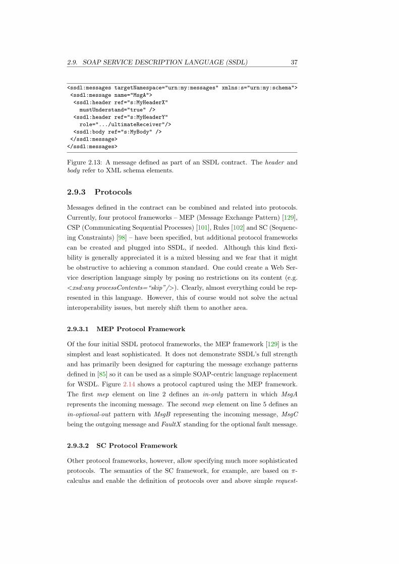
2.9. SOAP SERVICE DESCRIPTION LANGUAGE (SSDL) 37
<ssdl:messages targetNamespace="urn:my:messages" xmlns:s="urn:my:schema">
<ssdl:message name="MsgA">
<ssdl:header ref="s:MyHeaderX"
mustUnderstand="true" />
<ssdl:header ref="s:MyHeaderY"
role=".../ultimateReceiver"/>
<ssdl:body ref="s:MyBody" />
</ssdl:message>
</ssdl:messages>
Figure 2.13: A message defined as part of an SSDL contract. The header andbody refer to XML schema elements.
2.9.3 Protocols
Messages defined in the contract can be combined and related into protocols.Currently, four protocol frameworks – MEP (Message Exchange Pattern) [129],CSP (Communicating Sequential Processes) [101], Rules [102] and SC (Sequenc-ing Constraints) [98] – have been specified, but additional protocol frameworkscan be created and plugged into SSDL, if needed. Although this kind flexi-bility is generally appreciated it is a mixed blessing and we fear that it mightbe obstructive to achieving a common standard. One could create a Web Ser-vice description language simply by posing no restrictions on its content (e.g.<xsd:any processContents=“skip”/>). Clearly, almost everything could be rep-resented in this language. However, this of course would not solve the actualinteroperability issues, but merely shift them to another area.
2.9.3.1 MEP Protocol Framework
Of the four initial SSDL protocol frameworks, the MEP framework [129] is thesimplest and least sophisticated. It does not demonstrate SSDL’s full strengthand has primarily been designed for capturing the message exchange patternsdefined in [85] so it can be used as a simple SOAP-centric language replacementfor WSDL. Figure 2.14 shows a protocol captured using the MEP framework.The first mep element on line 2 defines an in-only pattern in which MsgArepresents the incoming message. The second mep element on line 5 defines anin-optional-out pattern with MsgB representing the incoming message, MsgCbeing the outgoing message and FaultX standing for the optional fault message.
2.9.3.2 SC Protocol Framework
Other protocol frameworks, however, allow specifying much more sophisticatedprotocols. The semantics of the SC framework, for example, are based on π-calculus and enable the definition of protocols over and above simple request-

38 CHAPTER 2. BACKGROUND
1 <ssdl:protocol xmlns:mep="urn:ssdl:mep:v1">
2 <mep:in-only>
3 <ssdl:msgref ref="MsgA" direction="in"/>
4 </mep:in-only>
5 <mep:in-optional-out>
6 <ssdl:msgref ref="MsgB" direction="in"/>
7 <ssdl:msgref ref="MsgC" direction="out"/>
8 <ssdl:msgref ref="FaultX" direction="out"/>
9 </mep:in-optional-out>
10 </ssdl:protocol>
Figure 2.14: Interaction protocol specified using the MEP SSDL protocol frame-work.
response patterns. Figure 2.15 illustrates a simple SC protocol that could notbe expressed using WSDL. The protocol defines that the service is initialisedby MsgA from another service referred to as U. Next, the defined service sendseither MsgB or MsgC to another service referred to as V. Then, it expects MsgDback from V and finally delivers MsgE back to U. Note that this specificationis declarative. It just defines what can happen. How it will eventually happen,is determined by the application logic that implements the contract.
1 <ssdl:protocol xmlns:mep="urn:ssdl:sc:v1">
2 <sc:sc>
3 <sc:participant name="U"/>
4 <sc:participant name="V"/>
5 <sc:protocol>
6 <sc:sequence>
7 <ssdl:msgref ref="MsgA" direction="in" sc:participant="U"/>
8 <sc:choice>
9 <ssdl:msgref ref="MsgB" direction="out" sc:participant="V"/>
10 <ssdl:msgref ref="MsgC" direction="out" sc:participant="V"/>
11 </sc:choice>
12 <ssdl:msgref ref="MsgD" direction="in" sc:participant="V"/>
13 <ssdl:msgref ref="MsgE" direction="out" sc:participant="U"/>
14 </sc:sequence>
15 </sc:protocol>
16 </sc:sc>
17 </ssdl:protocol>
Figure 2.15: Interaction protocol specified using the SC SSDL protocol frame-work.
2.9.4 Claimed Benefits
SSDL claims to take a more lightweight approach at describing Web Servicesthan incumbent standards such as WSDL [86]. By focusing on messages, SSDLexpects to encourage the creation of loosely-coupled and service-oriented ap-

2.10. SUMMARY 39
plications. Moreover, SSDL supports developers working directly with SOAPmessages as their fundamental abstraction and discourages them from thinkingabout exposing application objects directly as Web Services. Finally, providingmechanisms for capturing a service’s messaging behaviour allows exposing thisinformation to other services as part of the service description.
2.9.5 Tool Support
Unfortunately, almost no data exists that reports on experiences using SSDLas part of Web Services-based SOAs. There is only one set of published resultsfrom a project known to have used SSDL to model its services [130]. The lack ofempirical data makes it hard to assess the capabilities and potential of SSDL as aservice description language in a general sense. We believe that the main reasonwhy SSDL has not been used more widely is the lack of tool support for creatingand executing SSDL-based Web Services. On one side, there are no tools andprogramming abstractions that aid developers in modelling and implementingSSDL-based Web Services. On the other side, no SSDL-aware middleware exists,which could exploit the benefits of machine-processable protocol descriptions wedescribed in Section 2.7.
2.10 Summary
Diverse architectural styles and technologies exist for creating distributed soft-ware applications. Choosing a particular style normally has a number of conse-quences on the application design. RPC-based approaches attempt to shield thenetwork and provide developers with familiar programming abstractions basedon operation invocation semantics. Yet RPC applications tend to be tightlycoupled, brittle at distribution boundaries and limited in scalability. Messag-ing, on the other side, is well suited for integrating applications in a looselycoupled and scalable way. Traditional messaging approaches, however, requirecentralised infrastructure. In practice, this is a major obstacle for integratingcomponents across organisational, trust or geographical boundaries.
Web Services address interoperability and integration issues by providinga broad range of XML-based standards. They can be used for building ap-plications that adhere to SOA principles, where the primary abstraction forcommunication is one based on message passing. Yet simply using Web Ser-vices does not automatically lead to service-oriented systems. Indeed, there aretwo main views of Web Services, an RPC-centric view and a message-centric (ordocument-centric) view. In particular, we accepted that the design of WSDLis RPC-centric and can therefore be obstructive for building service-oriented

40 CHAPTER 2. BACKGROUND
applications (e.g. focus on operations rather than messages, insufficient con-trol over SOAP messages, high complexity, unable to capture message orderingconstraints over and above simple request-response patterns). We concludedthe chapter with a discussion of an alternative Web Services description lan-guage called SSDL, which provides a more message-centric approach for buildingservice-oriented applications.

Chapter 3
The Programming Model
} Things should be made as simple as possible, but no simpler. ~
— Albert Einstein
The programming model presented in Soya [12] allows developers to build SSDLservices in a straightforward manner. It encourages the creation of service-oriented applications without imposing unrealistic development burdens. De-velopers define message structures and protocols using metadata. Soya in turnleverages this information to infer SSDL contracts, which are utilised by itsruntime and can be exposed to other services.
Soya is built on top of the Windows Communication Foundation (WCF) [61]and its programming abstractions are partially based on the latter’s program-ming model, which offers a number of ways to implement services. While thisgenerality and flexibility is normally appreciated, it can also lead to confusion.Although WCF can certainly be used to build message-oriented applications,choosing the wrong programming abstractions can easily corral a developerinto creating RPC-like applications. Conversely, Soya’s programming modelis more restrictive. In fact, it aims at forcing developers to think in termsof one-way messages and therefore encourages the creation of loosely coupledmessage-oriented systems.
3.1 Development Life Cycle
Creating and deploying a service implementation, normally involves the follow-ing basic tasks [131]:
1. defining the service contract including messages and protocols;
2. implementing the contracts;
41

42 CHAPTER 3. THE PROGRAMMING MODEL
3. configuring the service;
4. deploying the artefacts created in the previous steps.
Typically, the contractual data is defined declaratively using C# attributes.Contracts are implemented by means of C# code and configuration-related as-pects are specified in XML. Although different ways exist to creating theseartefacts, we favour the one just described. Figure 3.1 shows these artefacts, towhich we will collectively refer to as service implementation.
Application
Logic
C#
Configuration
XML
SSDL Contract
C# & Attributes
Service Implementation
Figure 3.1: The different artefacts of a service implementation. C# code is usedto implement application logic, metadata attributes describe the SSDL contractand XML configuration files specify service endpoints, security settings, etc.
3.2 Defining SSDL Contracts Using Metadata
C# attributes are a mechanism for declaratively embedding metadata in C#source code. This metadata adds additional information to the code that canbe retrieved, processed and interpreted by other programs. In WCF’s pro-gramming model, service and message contracts are typically defined in thisdeclarative manner [36]. Soya reuses this programming model and providesadditional SSDL-specific attributes and functionality. On the one hand, thisallows developers to define the structure of messages supported by an SSDLcontract. On the other hand, it can be used to describe how these messages re-late to each other using different protocol frameworks. This attribute-orientedapproach makes it possible to specify contract data with very little code, yetprovides extensive control over the contract when warranted.
In Soya, we have adopted the attribute-oriented programming model for thefollowing reasons:
• less code and hence less scope for error introduction;
• more easily maintainable due to single source location;
• seamless integration with WCF’s programming model and provision offamiliar idioms to existing C# programmers.

3.2. DEFINING SSDL CONTRACTS USING METADATA 43
Defining contracts using C# attributes is a fundamental concept in bothWCF and Soya and different attributes are available for different parts of thecontract. Figure 3.2 clarifies the interrelationship between service implementa-tion and inferred SSDL contracts.
C#
XML
Schemas
Messages
Protocols
Endpoints
Service Impl. SSDL Contract
[DataContract]
[MessageContract]
[ProtocolContract]
[Config]
Figure 3.2: SSDL contracts are inferred mostly from C# source code and at-tributes. Endpoints are usually defined in an XML configuration file.
3.2.1 Defining Messages
Where possible, we reused existing WCF attributes to make the transition fromWCF to Soya as smooth as possible. For concepts unique to SSDL, however,we introduced additional attributes (e.g. SSDL message names and namespaces,protocols, etc.). The following code snippet shows how message contracts aredefined in Soya:
[SsdlMessageContract] // Soya attribute
public class MsgA {
[MessageHeader] public string MyHeader;
[MessageBodyMember] public MyData MyBody;
}
The MessageHeader attribute maps a class member to a SOAP header. Thevalue of MyHeader, for example, is mapped to a primitive XML data type (i.e.string). Similarly, MessageBodyMember maps to a SOAP body. Above, thevalue of MyBody is mapped to a XML complex type, because it references acustom type. As a result, it is necessary to define how this type is serialised anddeserialised to and from XML, respectively. This is done by annotating the classwith a DataContract and every serialisable class member with a DataMemberattribute:

44 CHAPTER 3. THE PROGRAMMING MODEL
[DataContract(Namespace = "urn:my:schema")] // WCF attribute
public class MyData {
[DataMember] public int id;
[DataMember] public string code;
}
Attributes can take additional property parameters that are used to overridedefault values and give developers more control over the message data. Forexample, to explicitly specify the qualified name of the SSDL message elementin the code above, one simply defines values for the Name and Namespaceproperties:
[SsdlMessageContract(Name="...", Namespace="...")]
From the example code above, Soya can infer the following XML Schemaand SSDL message element, which are part of the SSDL contract:
<xs:element name="MyHeader" type="xs:string"/>
<xs:element name="MyBody" type="s:MyData"/>
<xs:complexType name="MyData">
<xs:sequence>
<xs:element name="id" type="xs:int"/>
<xs:element name="code" type="xs:string"/>
</xs:sequence>
</xs:complexType>
...
<ssdl:message name="MsgA">
<ssdl:header ref="s:MyHeader"/>
<ssdl:body ref="s:MyBody"/>
</ssdl:message>
3.2.1.1 Faults
Faults are defined in a similar way to messages. Since SSDL 1.0 does not allowfor capturing of the headers of a fault, we only need to define one class thatrepresents the detail element of the SOAP fault message1.
[SsdlFaultContract]
[DataContract]
public class FaultX {
[DataMember] public string Code;
[DataMember] public string Description;
}
1A more extensive discussion of issues related to SSDL faults is provided in Section 6.9.
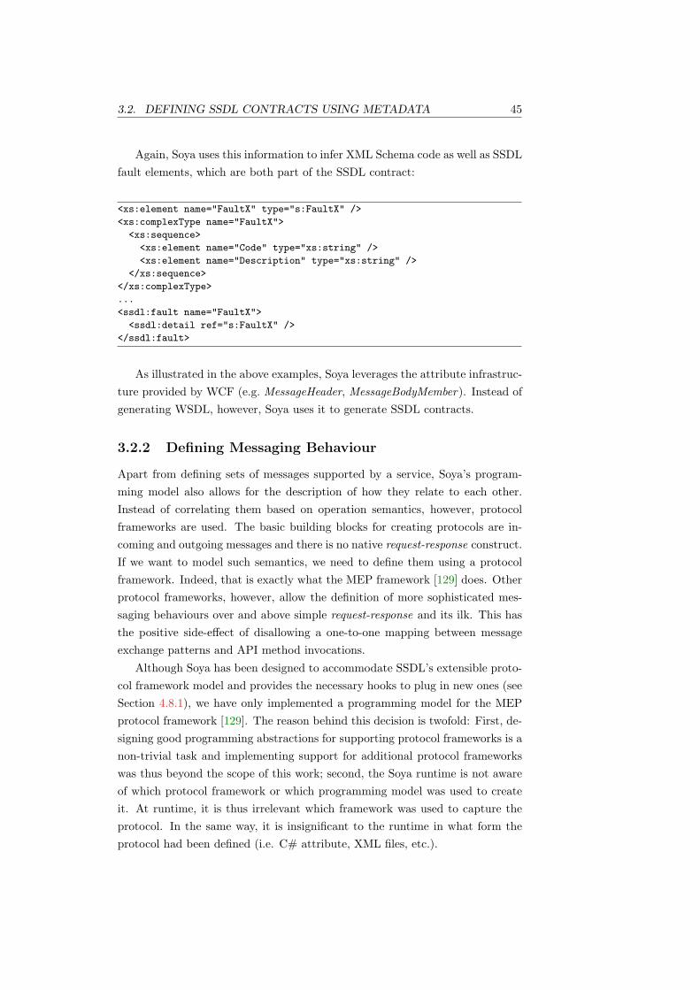
3.2. DEFINING SSDL CONTRACTS USING METADATA 45
Again, Soya uses this information to infer XML Schema code as well as SSDLfault elements, which are both part of the SSDL contract:
<xs:element name="FaultX" type="s:FaultX" />
<xs:complexType name="FaultX">
<xs:sequence>
<xs:element name="Code" type="xs:string" />
<xs:element name="Description" type="xs:string" />
</xs:sequence>
</xs:complexType>
...
<ssdl:fault name="FaultX">
<ssdl:detail ref="s:FaultX" />
</ssdl:fault>
As illustrated in the above examples, Soya leverages the attribute infrastruc-ture provided by WCF (e.g. MessageHeader, MessageBodyMember). Instead ofgenerating WSDL, however, Soya uses it to generate SSDL contracts.
3.2.2 Defining Messaging Behaviour
Apart from defining sets of messages supported by a service, Soya’s program-ming model also allows for the description of how they relate to each other.Instead of correlating them based on operation semantics, however, protocolframeworks are used. The basic building blocks for creating protocols are in-coming and outgoing messages and there is no native request-response construct.If we want to model such semantics, we need to define them using a protocolframework. Indeed, that is exactly what the MEP framework [129] does. Otherprotocol frameworks, however, allow the definition of more sophisticated mes-saging behaviours over and above simple request-response and its ilk. This hasthe positive side-effect of disallowing a one-to-one mapping between messageexchange patterns and API method invocations.
Although Soya has been designed to accommodate SSDL’s extensible proto-col framework model and provides the necessary hooks to plug in new ones (seeSection 4.8.1), we have only implemented a programming model for the MEPprotocol framework [129]. The reason behind this decision is twofold: First, de-signing good programming abstractions for supporting protocol frameworks is anon-trivial task and implementing support for additional protocol frameworkswas thus beyond the scope of this work; second, the Soya runtime is not awareof which protocol framework or which programming model was used to createit. At runtime, it is thus irrelevant which framework was used to capture theprotocol. In the same way, it is insignificant to the runtime in what form theprotocol had been defined (i.e. C# attribute, XML files, etc.).

46 CHAPTER 3. THE PROGRAMMING MODEL
This separation between the protocol framework, the programming modeland the runtime is clearly desirable, as it allows Soya to be extended in multipledirections using different approaches. Further, it enables us to evaluate theruntime behaviour in a generic way, without restricting our observations to aparticular protocol framework or programming abstraction.
3.2.2.1 Modelling MEP-Based Interactions
An SSDL contract is defined by annotating the service interface with a Service-Contract attribute. Messaging behaviour is captured using SsdlProtocolCon-tract and MEP attributes. The following lines show how simple MEP-basedinteractions can be modelled using Soya:
1 [ServiceContract(Namespace = "urn:my:contract")]
2 [SsdlProtocolContract(Namespace = "urn:my:protocol")]
3 public interface IService {
4 [Mep(Style=MepStyle.InOnly)]
5 void Process(MsgA msg);
6
7 [Mep(Style=MepStyle.InOptionalOut, Out=typeof(MsgC),
8 Fault=typeof(FaultX))]
9 void Process(MsgB msg);
10 }
The attribute on the first method declaration defines an in-only MEP inwhich MsgA represents the incoming message. The second method declarationdefines an in-optional-out MEP with MsgB representing the incoming message,MsgC being the outgoing message and FaultX standing for the optional faultmessage. From this code, Soya can generate the following SSDL protocol:
<ssdl:protocol targetNamespace="urn:my:protocol"
xmlns:mep="urn:ssdl:mep:v1">
<mep:in-only>
<ssdl:msgref ref="m:MsgA" direction="in"/>
</mep:in-only>
<mep:in-optional-out>
<ssdl:msgref ref="m:MsgB" direction="in"/>
<ssdl:msgref ref="m:MsgC" direction="out"/>
<ssdl:msgref ref="m:FaultX" direction="out"/>
</mep:in-optional-out>
</ssdl:protocol>
These examples show how Soya uses type and attribute metadata to inferSSDL contracts. They also give an idea of how little additional code is necessaryto create an entire SSDL contract including XML Schema definitions, methodand fault declarations and protocol descriptions.
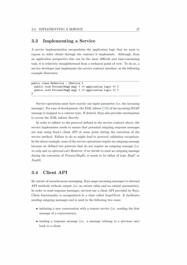
3.3. IMPLEMENTING A SERVICE 47
3.3 Implementing a Service
A service implementation encapsulates the application logic that we want toexpose to other clients through the contract it implements. Although, froman application perspective this can be the most difficult and time-consumingtask, it is relatively straightforward from a technical point of view. To do so, aservice developer just implements the service contract interface, as the followingexample illustrates:
public class MyService : IService {
public void Process(MsgA msg) { /* application logic */ }
public void Process(MsgB msg) { /* application logic */ }
}
Service operations must have exactly one input parameter (i.e. the incomingmessage). For ease of development, the XML infoset [132] of the incoming SOAPmessage is mapped to a custom type. If desired, Soya also provides mechanismsto access the XML infoset directly.
In order to adhere to the protocol defined in the service contract above, theservice implementer needs to ensure that potential outgoing response messagesare sent using Soya’s client API at some point during the execution of theservice method. Failure to do so might lead to protocol validation exceptions.In the above example, none of the service operations require an outgoing messagebecause we defined two patterns that do not require an outgoing message (i.e.in-only and in-optional-out) However, if we decide to send an outgoing messageduring the execution of Process(MsgB), it needs to be either of type MsgC orFaultX.
3.4 Client API
By nature of asynchronous messaging, Soya maps incoming messages to internalAPI methods without output (i.e. no return value and no output parameters).In order to send response messages, services use a client API provided by Soya.Client functionality is encapsulated in a class called SoyaClient. It facilitatessending outgoing messages and is used in the following two cases:
• initiating a new conversation with a remote service (i.e. sending the firstmessage of a conversation);
• sending a response message (i.e. a message relating to a previous one)back to a client.
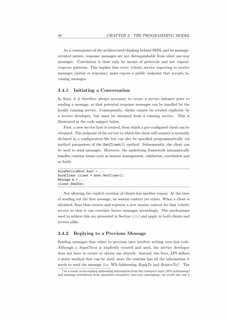
48 CHAPTER 3. THE PROGRAMMING MODEL
As a consequence of the architectural thinking behind SSDL and its message-oriented nature, response messages are not distinguishable from other one-waymessages. Correlation is done only by means of protocols and not request-response patterns. This implies that every (client) service expecting to receivemessages (initial or response), must expose a public endpoint that accepts in-coming messages.
3.4.1 Initiating a Conversation
In Soya, it is therefore always necessary to create a service instance prior tosending a message, so that potential response messages can be handled by thelocally running service. Consequently, clients cannot be created explicitly bya service developer, but must be obtained from a running service. This isillustrated in the code snippet below.
First, a new service host is created, from which a pre-configured client can beobtained. The endpoint of the service to which the client will connect is normallydeclared in a configuration file but can also be specified programmatically viamethod parameters of the GetClient() method. Subsequently, the client canbe used to send messages. Moreover, the underlying framework automaticallyhandles runtime issues such as session management, validation, correlation andso forth:
SoyaServiceHost host = ...
SoyaClient client = host.GetClient();
Message m = ...
client.Send(m);
Not allowing the explicit creation of clients has another reason: At the timeof sending out the first message, no session context yet exists. When a client isobtained, Soya thus creates and registers a new session context for that (client)service so that it can correlate future messages accordingly. The mechanismsused to achieve this are presented in Section 4.3.2 and apply to both clients andservers alike.
3.4.2 Replying to a Previous Message
Sending messages that relate to previous ones involves writing even less code.Although a SoyaClient is implicitly created and used, the service developerdoes not have to create or obtain one directly. Instead, the Soya API definesa static method that can be used, since the runtime has all the information itneeds to send the message (i.e. WS-Addressing ReplyTo and RelatesTo)2. The
2As a result of decoupling addressing information from the transport layer (WS-Addressing)and message correlation from operation semantics (one-way messaging), we could also use a

3.5. CONFIGURING A SERVICE 49
following code snippet shows a service sending a response that will automaticallybe correlated with the one currently processed:
public void Process(MyMessage m) {
/* some application logic */
Message response = ...
SoyaServiceHost.Reply(response);
}
3.5 Configuring a Service
The final step in creating a deployable service implementation consists of writingthe service configuration. Although the configuration can be specified impera-tively in code, the more flexible and common way is to define the settings inXML.
The configuration file captures different aspects of the service, such as theendpoint address, where it will be listening for incoming requests, the transportprotocol and message encoding used for sending and receiving messages, whetherit should use security, reliability and so forth. The following lines, define whichclass implements the contract and where and how it will be available.
<system.serviceModel>
<services>
<service name="MyService">
<host>
<baseAddresses>
<add baseAddress="http://my.service.com/"/>
</baseAddresses>
</host>
<endpoint address="basic"
binding="BasicHttpBinding"
contract="IService" />
</service>
</services>
</system.serviceModel>
Given the configuration data, Soya infers the last part that was missing inthe SSDL contract, namely the SSDL endpoint:
<ssdl:endpoints>
<ssdl:endpoint xmlns:wsa="http://www.w3.org/2004/12/addressing">
<wsa:Address>http://my.service.com/basic</wsa:Address>
</ssdl:endpoint>
</ssdl:endpoints>
different transport protocol for the response (i.e. HTTP for the initial message and SMTP forthe response.)

50 CHAPTER 3. THE PROGRAMMING MODEL
The complete SSDL contract that is inferred from the example code in thissection is shown in Figure 3.3.
3.6 Client-Server Symmetry
In a truly service-oriented environment, services communicate freely with eachother by actively sending or receiving messages at any given point in a conver-sation. The terms client and server can thus be deceptive to some extent andtheir roles might even change in a dynamic fashion during a single conversation.We thus apply these terms more out of convenience than correctness. Conse-quently, we use client to refer to a service that initiate a conversation and serverfor the other service.
From a message processing point of view, it is not necessary to distinguishbetween the two roles. Indeed, it is irrelevant whether an incoming messageis a response from a server or a request from a client. In the same way, it isirrelevant whether an outgoing message is a response sent back to a client or arequest sent to a server.
This makes it possible to use Soya on both client and server side withoutmaking any changes to the runtime or the programming model. What changes,however, is the definition of the SSDL contract. To better illustrate this, con-sider the following example: ServiceA is a server in the traditional sense, becauseit waits for incoming messages, processes them and sends response messages backto clients. A possible contract definition that captures this messaging behaviourusing Soya’s programming model could look like this:
public interface ServiceA {
[Mep(Style=MepStyle.InOut, Out=typeof(MsgB)]
void Process(MsgA msg);
}
Conversely, ServiceB is a client in the traditional sense, because it first sendsa message to a server and then expects a response message to come back. Acontract definition for a compatible client’s messaging behaviour could thereforebe:
public interface ServiceB {
[Mep(Style=MepStyle.OutIn, Out=typeof(MsgA)]
void Process(MsgB msg);
}
Note that we only changed the messaging behaviour (i.e. out-in instead ofin-out). This illustrates that the programming model can be used for any kind

3.6. CLIENT-SERVER SYMMETRY 51
<ssdl:contract xmlns:ssdl="urn:ssdl:v1" targetNamespace="urn:my:contract">
<ssdl:schemas>
<xs:schema targetNamespace="urn:my:schema"
xmlns:xs="http://www.w3.org/2001/XMLSchema"
xmlns:tns="urn:my:schema">
<xs:element name="MyHeader" type="xs:string" />
<xs:element name="MyBody" type="tns:MyData" />
<xs:element name="MyData" type="tns:MyData" />
<xs:element name="FaultX" type="tns:FaultX" />
<xs:complexType name="MyData">
<xs:sequence>
<xs:element minOccurs="0" name="code" type="xs:string" />
<xs:element minOccurs="0" name="id" type="xs:int" />
</xs:sequence>
</xs:complexType>
<xs:complexType name="FaultX">
<xs:sequence>
<xs:element minOccurs="0" name="Code" type="xs:string" />
<xs:element minOccurs="0" name="Description" type="xs:string" />
</xs:sequence>
</xs:complexType>
</xs:schema>
</ssdl:schemas>
<ssdl:messages targetNamespace="urn:my:message" xmlns:ns1="urn:my:schema">
<ssdl:message name="MsgA">
<ssdl:header ref="ns1:MyHeader" mustUnderstand="false" relay="false" />
<ssdl:body ref="ns1:MyBody" />
</ssdl:message>
<ssdl:message name="MsgB">
<ssdl:header ref="ns1:MyHeader" mustUnderstand="false" relay="false" />
<ssdl:body ref="ns1:MyBody" />
</ssdl:message>
<ssdl:message name="MsgC">
<ssdl:header ref="ns1:MyHeader" mustUnderstand="false" relay="false" />
<ssdl:body ref="ns1:MyBody" />
</ssdl:message>
<ssdl:fault name="FaultX">
<ssdl:detail ref="ns1:FaultX" />
</ssdl:fault>
</ssdl:messages>
<ssdl:protocols>
<ssdl:protocol targetNamespace="urn:my:protocol"
xmlns:mep="urn:ssdl:mep:v1">
<mep:in-only xmlns:ns2="urn:my:message">
<ssdl:msgref ref="ns2:MsgA" direction="in" />
</mep:in-only>
<mep:in-optional-out xmlns:ns2="urn:my:message">
<ssdl:msgref ref="ns2:MsgB" direction="in" />
<ssdl:msgref ref="ns2:MsgC" direction="out" />
<ssdl:msgref ref="ns2:FaultX" direction="out" />
</mep:in-optional-out>
</ssdl:protocol>
</ssdl:protocols>
<ssdl:endpoints>
<ssdl:endpoint xmlns:wsa="http://www.w3.org/2004/12/addressing">
<wsa:Address>http://my.service.com/basic</wsa:Address>
</ssdl:endpoint>
</ssdl:endpoints>
</ssdl:contract>
Figure 3.3: The complete SSDL contract inferred from C# attribute meta data.
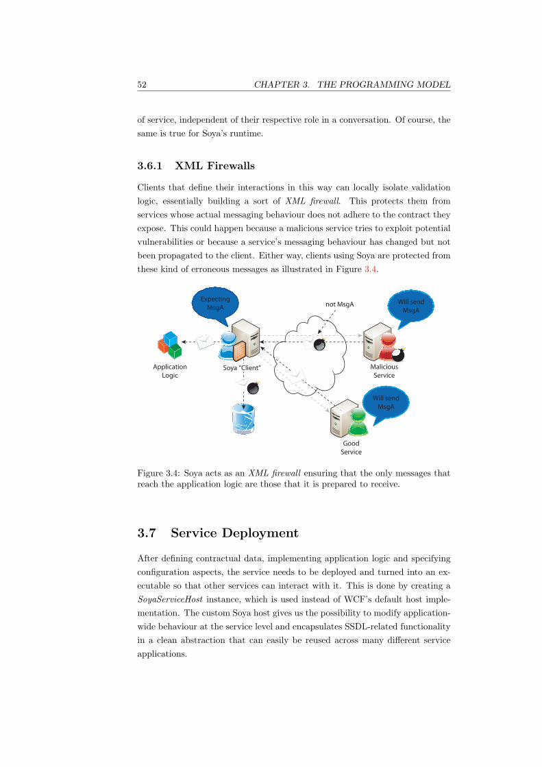
52 CHAPTER 3. THE PROGRAMMING MODEL
of service, independent of their respective role in a conversation. Of course, thesame is true for Soya’s runtime.
3.6.1 XML Firewalls
Clients that define their interactions in this way can locally isolate validationlogic, essentially building a sort of XML firewall. This protects them fromservices whose actual messaging behaviour does not adhere to the contract theyexpose. This could happen because a malicious service tries to exploit potentialvulnerabilities or because a service’s messaging behaviour has changed but notbeen propagated to the client. Either way, clients using Soya are protected fromthese kind of erroneous messages as illustrated in Figure 3.4.
Malicious
Service
Application
Logic
Good
Service
Soya “Client”
Will send
MsgA
Will send
MsgA
not MsgAExpecting
MsgA
Figure 3.4: Soya acts as an XML firewall ensuring that the only messages thatreach the application logic are those that it is prepared to receive.
3.7 Service Deployment
After defining contractual data, implementing application logic and specifyingconfiguration aspects, the service needs to be deployed and turned into an ex-ecutable so that other services can interact with it. This is done by creating aSoyaServiceHost instance, which is used instead of WCF’s default host imple-mentation. The custom Soya host gives us the possibility to modify application-wide behaviour at the service level and encapsulates SSDL-related functionalityin a clean abstraction that can easily be reused across many different serviceapplications.

3.7. SERVICE DEPLOYMENT 53
The host is created using a reference to the class that implements the servicecontract. Upon opening the host, Soya reflects over the service and messagetypes, processes configuration files and builds the runtime from this information(see Section 4.8). The following two lines show the API usage for deploying aservice implementation (in this case MyService):
host = new SoyaServiceHost(typeof(MyService));
host.Open();


Chapter 4
The Runtime Environment
} Perfection in engineering is achieved not when there is nothing left to add,but when there is nothing left to take away. ~
— Antoine de Saint-Exupery
Apart from presenting developers with programming abstractions for creatingSSDL-based Web Services, Soya [12] also provides a runtime environment forexecuting them. The runtime infrastructure processes incoming and outgoingSOAP messages and ensures contract conformance in terms of their structureand ordering. Further, it features facilities for correlating and dispatching bothincoming and outgoing messages.
4.1 Introduction
The Soya runtime can be seen as a kind of middleware software that addsSSDL-specific functionality and semantics to an existing SOAP engine. It isbuilt on top of the Windows Communication Foundation (WCF) [61], whichis a communication platform that provides support for processing SOAP mes-sages and a number of other Web Services specifications. Choosing an existingplatform, allowed us to concentrate on implementing SSDL protocol supportand delegate issues such as efficient processing of SOAP messages, failure recov-ery, implementing support for different bindings and so forth to the underlyingframework. Figure 4.1 schematically illustrates how the Soya runtime is trans-parently placed between WCF and the application logic.
Soya leverages WCF in a number of ways. It alters its default runtimebehaviour by means of configuration. Moreover, it replaces parts of the defaultWCF runtime logic with custom components (e.g. custom message correlation,state management or operation invocation implementations). This is done either
55

56 CHAPTER 4. THE RUNTIME ENVIRONMENT
Middle Tier
Client
Soya Runtime
Ser
vic
eDis
pa
tch
AP
I
Correlation &
ValidationWC
F
Figure 4.1: The Soya runtime can be thought of as an additional layer betweenWeb Service middleware and application logic.
by directly plugging them into the WCF runtime or by injecting behaviourswhich in turn add the custom logic. All of these custom components are invokedby WCF at various stages of service execution. Furthermore, Soya includes anumber of WCF-independent components that likewise contribute functionality(e.g. message and protocol validation logic) to the overall system. They are,however, not directly invoked by WCF. Figure 4.2 schematically illustrates theseinterrelationships.
Soya Runtime Components
Service Implementation
WCF
Custom Impl
Behaviors
Configuration
Figure 4.2: Configuration files, injected behaviours and custom implementationsmodify WCF’s default runtime behaviour. Above them is another layer of SSDLfunctionality that is independent of WCF.
4.2 Runtime Components
The components that constitute the runtime each provide specific functionalitythat are important for the overall runtime behaviour. Consequently, most ofthem are involved in processing every incoming and outgoing message. In par-ticular, the following seven components realise Soya’s core functionality. Apartfrom the last component, the given order reflects the sequence in which they
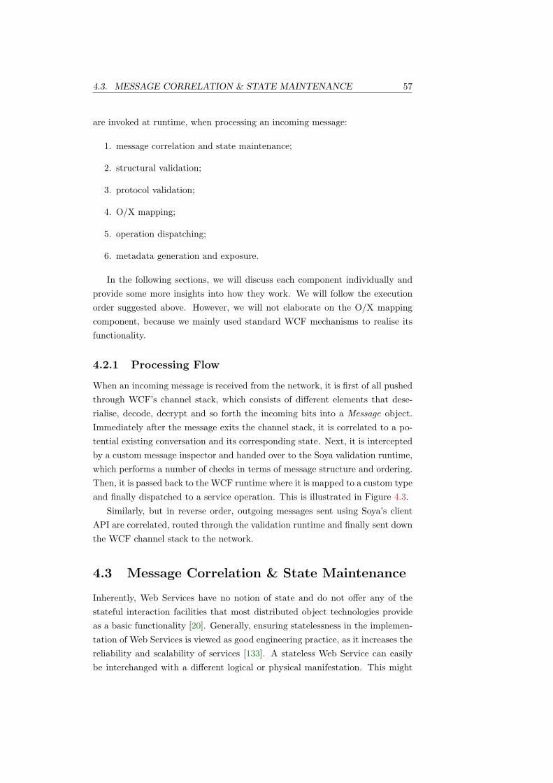
4.3. MESSAGE CORRELATION & STATE MAINTENANCE 57
are invoked at runtime, when processing an incoming message:
1. message correlation and state maintenance;
2. structural validation;
3. protocol validation;
4. O/X mapping;
5. operation dispatching;
6. metadata generation and exposure.
In the following sections, we will discuss each component individually andprovide some more insights into how they work. We will follow the executionorder suggested above. However, we will not elaborate on the O/X mappingcomponent, because we mainly used standard WCF mechanisms to realise itsfunctionality.
4.2.1 Processing Flow
When an incoming message is received from the network, it is first of all pushedthrough WCF’s channel stack, which consists of different elements that dese-rialise, decode, decrypt and so forth the incoming bits into a Message object.Immediately after the message exits the channel stack, it is correlated to a po-tential existing conversation and its corresponding state. Next, it is interceptedby a custom message inspector and handed over to the Soya validation runtime,which performs a number of checks in terms of message structure and ordering.Then, it is passed back to the WCF runtime where it is mapped to a custom typeand finally dispatched to a service operation. This is illustrated in Figure 4.3.
Similarly, but in reverse order, outgoing messages sent using Soya’s clientAPI are correlated, routed through the validation runtime and finally sent downthe WCF channel stack to the network.
4.3 Message Correlation & State Maintenance
Inherently, Web Services have no notion of state and do not offer any of thestateful interaction facilities that most distributed object technologies provideas a basic functionality [20]. Generally, ensuring statelessness in the implemen-tation of Web Services is viewed as good engineering practice, as it increases thereliability and scalability of services [133]. A stateless Web Service can easilybe interchanged with a different logical or physical manifestation. This might

58 CHAPTER 4. THE RUNTIME ENVIRONMENT
accept
messages
correlation and
state maintenance
structural
validation
protocol
validation
O/X
mapping
operation
dispatching
execute
application
logic
intercept
1
2
34
5
6
7
8Service
MessageFormatter
ContextProvider
protocol
Channel Stack
Dispatcher
encoding
transport
MessageInspector
OperationInvoker
WC
F R
un
tim
e
XsdValidator
MessageLocator
ProtocolStateMachine
Soya Validation R.T.
www
Figure 4.3: Message processing flow. Messages pass through a number of com-ponents that perform various tasks and activities before they are dispatched toa service operation.
be necessary, as a result of an increase in server load or failure of a particularservice instance.
Not being able to relate consecutive messages into ongoing conversations,however, allows for the creation of only very limited distributed systems [20].Often, applications need to logically relate a sequence of messages, such that theresults of one message exchange can be used as a basis for others. In order toachieve this, exchanged messages need to contain contextual information, whichenables services to identify ongoing conversations [134].
A service can use the context information contained in the incoming messageto relate it to its internal state. To maintain the benefits of statelessness, aservice’s internal state needs to be kept in other system components (e.g. anenterprise-grade database), so that other stateless service instances can accessit. This allows a service’s behaviour to appear stateful, while its implementationin reality remains stateless. Figure 4.4 illustrates these concepts graphically.
Indeed, all of Soya’s runtime components are implemented in a stateless fash-ion and only a minimum of stateful objects are maintained in session context.In fact, the only stateful object that is maintained across message exchanges isa copy of protocol state machine instances (see Section 4.5.6.

4.3. MESSAGE CORRELATION & STATE MAINTENANCE 59
Data TierLogic Tier
Context
Store
Soya # I
Soya # 2
Soya # 3
Load
BalancerClient
Get Ctx
Get Ctx
Get Ctx
Figure 4.4: Externalising the session context allows service instances to be phys-ically interchanged between message exchanges without loosing the session con-text. Adapted from [135].
4.3.1 Leveraging WS-Addressing
SSDL is predicated on SOAP and WS-Addressing [13]. In Soya, relating in-coming messages to conversations and internal state is consequently done bymeans of MessageID and RelatesTo headers. Simply put, the RelatesTo headerof every new incoming or outgoing message is linked with the MessageID headerof a previous message and thus forms an ordered sequence of header pairs (i.e.messages). For example:
(1), (2, 1), (3, 2), (4, 3), . . .
Although stateful interactions between services could also be realised usingendpoint references and reference parameters1, we did not choose this approachbecause it implies the use of custom – and thus potentially non-standardised –SOAP headers. In contrast, our approach ensures a higher degree of interoper-ability, as only standardised WS-Addressing headers are used.
4.3.2 Session Context Management
In accordance with above discussions, session context (i.e. state) is stored sepa-rately and referenced by contextual information in the form of WS-Addressingheaders. In fact, session context stored in Soya is always associated with thelast processed message. This means that if a new message arrives, it can be lo-cated based on the message’s RelatesTo header. If no session exists yet (i.e. firstmessage of a conversation), one is created. At the same time, Soya associates
1W3C, “Web services addressing”, 2004, Section 2

60 CHAPTER 4. THE RUNTIME ENVIRONMENT
the context with the new MessageID and updates the session context store (e.g.a database) to reflect the fact that both future incoming or outgoing messagesmust relate to the one just received.
This behaviour is best illustrated with an example. Figure 4.5 shows a simpleconversation that spans multiple logically connected messages. A client sendsan initial message with id 001. Because it does not relate to a previous one,the service creates a new context and stores it (e.g. in a database). After theservice has finished processing the message, the in-memory context is destroyedin order to free resources. Some time later, the client sends a new message withid 002. By setting the RelatesTo header to the previous message, it indicatesthat it is part of the same conversation. Upon receiving the message, the serviceuses the RelatesTo information to retrieve the previously stored session contextand load it back into memory. At the same time, it updates the context storeto reflect the fact that the message with id 002 has been consumed (by thecurrent operation) and that future messages of the same conversation will needto relate to the new id (i.e. 002). After processing message 002, the servicesends a response back to the client. Soya’s client API automatically correlatesthe message by adding appropriate header information (i.e. setting MessageIDto 003 and RelatesTo to 002) (see Section 3.4).
Client ContextProvider Context ContextStore Service
MessageID: 001
RelatesTo: --- Create()
Reply
...
...
...
...
...
MessageID: 002
RelatesTo: 001
MessageID: 004
RelatesTo: 003
Process
Message(001)
Process
Message(002)
MessageID: 003
RelatesTo: 002
SetHeaders()
MessageID: 003
RelatesTo: 002
Load()
...and so forth...
Retrieve(002)
Update(ctx,002)
Store(001,ctx)
Update(ctx,003)
SoyaServiceHost
Figure 4.5: A typical conversation that involves creating, retrieving and updat-ing the session context.

4.3. MESSAGE CORRELATION & STATE MAINTENANCE 61
4.3.3 Session Context Lifetime and Maintenance
In Soya, the lifetime of a session context object is treated differently dependingon whether it was originally created by a client (i.e. SoyaClient) or by a service(i.e. upon reception of an initial message).
4.3.3.1 Created by Clients
If a program initiates a conversation using a SoyaClient (see Section 3.4), thesession context it creates is implicitly bound to its lifetime. This behaviour isbased on the assumption that a user who disposes of the client, is no longer in-terested in the conversation with the service. Additionally, this strategy avoidsmemory leaks caused by session context zombies. Consequently, the client in-stance needs to be kept in memory for the entire duration of the conversation inorder to maintain the session context. Indeed, this behaviour has proven to besufficiently adequate for the services created in our case study (see Chapter 5).
4.3.3.2 Created by Services
In contrast, the session context created on the server side has no preliminarilyconfined lifetime2. The session context is not destroyed automatically, becauseit cannot be generally determined in advance whether the client will continuethe conversation at some point. On the one hand, SSDL protocol descriptionscan have optional constructs (e.g. out-optional-in). On the other hand, theydo not constrain the temporal extension between consecutive interactions (e.g.if a service has not sent a message after t time, it does not mean that it willnot send it after t + ∆). Of course, this can pose performance problems inproduction environments, since only a finite number of session context objectscan be indefinitely kept in memory. This issue can be addressed using diversestrategies that persist session context after a certain amount of idle time (e.g.into a database). At the same time, this has the positive side-effect of increasingapplication scalability and reliability as we discussed in Section 4.3. Determiningand adjusting the parameters which govern when session context objects shouldbe persisted or destroyed (e.g. client idle time, client activity, server load, etc.)can vary significantly between applications and is thus not within the scope ofthis work.
2This is only partially true, because it is actually destroyed if the service host is beingdisposed of. Yet a persistent session context storage implementation (e.g. database, XML file,etc.) could be used to maintain session state that transcends server restarts. In the currentSoya release this has, however, not been implemented.

62 CHAPTER 4. THE RUNTIME ENVIRONMENT
4.3.4 Synchronisation of Session Context Access
Inherently, an SSDL engine such as Soya operates in an environment where alot of processing has to be done concurrently because many clients may accessa service at the same time. As a consequence, Soya’s runtime has been delib-erately implemented in a stateless fashion and does not cause synchronisationproblems. Yet access to stateful objects, such as the session context, needs tobe synchronised between concurrently running threads. Still, communicatingwith any number of clients simultaneously does not cause any session contextsynchronisation problems, because the server maintains a separate context foreach conversation individually.
As soon as clients send many messages simultaneously within the same con-versation, however, many concurrently running threads will be created on theserver that can access the session context simultaneously. Therefore, access tothe session context needs to be synchronised. To guarantee a consistent, in-sequence processing of incoming and outgoing messages according to a service’sprotocol, we demarcate the message processing flow into a critical section. Insidethis section, no other thread can access the session context while one is alreadyprocessing a message for the same context. The critical section begins when thesession context is assigned to a thread and ends when the message is dispatchedto the application (i.e. when the protocol state machine reflects the new stateof the conversation). In order to enter the critical section, competing threadsmust acquire a processing context. This mechanism is shown schematically inFigure 4.6.
00
10
02
00
3
00
10
02
00
3
Client ContextProvider Context SoyaRuntime Service SoyaServiceHost
Send(001)
Send(002)
Send(003)
AcquireProcCtx(001)
ProcCompleted()
Notify()
Invoke()
Invoke()
Process(001)
Process(002)
...
...
...
...
...
...
ProcCompleted()
Notify()
Reply()
AcquireProcCtx(002)
AcquireProcCtx(003)
Must wait
for “001”
Lock ctx
for “001”
ProcessOut(003)
Figure 4.6: Multiple threads that are using the same session context are syn-chronised at the message-level in order to guarantee a consistent, in-sequenceprocessing.

4.4. STRUCTURAL VALIDATION 63
Not only do we need to synchronise access to the session context for incomingmessages but also for outgoing messages. This is shown in the bottom part ofFigure 4.6, where the service sends a response message via Soya’s client API.Analogous to the procedure for handling incoming messages, Soya ensures thatno other messages are currently being processed in the same conversation. Itthus likewise needs to first acquire the processing context before it can send anoutgoing message.
4.4 Structural Validation
The structure of incoming and outgoing messages is validated against bothschema and message definitions specified in the service’s SSDL contract. If oneof the two validation steps fails, processing stops and the message is rejected.
Both message header and body elements are taken into consideration forvalidation. The former, however, cannot be validated as strictly as the latter,because this would interfere with the SOAP processing model’s extensibilitymechanism [11]. SOAP nodes can add infrastructure information (e.g. address-ing, security, etc.) that is likely not defined in the SSDL contract per se. Yet thisdoes not mean that the structure of these messages is invalid. For this reason,only headers which have been defined in the contract are actually validated,while others are silently ignored. In contrast, if the message body containselements that are not present in the contract, validation fails.
First, the message is validated against the schema defined in the contract(e.g. XML Schema validation). Next, Soya tries to match it with a messagedescription of the SSDL contract. This ensures that the particular combinationof header and body elements is actually a contractually defined message. Forexample, assume that header h and body b are both described in the contract’sschema section but not grouped together as a message. If a SOAP messagewith the given elements (i.e. h, b) is processed, schema validation succeeds, yetmessage validation will fail.
4.5 Protocol Validation
One of the core components of the Soya runtime is the protocol state machine,which validates the correct sequence of exchanged messages and decides towhich service method incoming messages are to be dispatched. It is built atdeployment-time from the protocol information captured in the SSDL contract.Although the classes responsible for building it from protocols are inevitablyprotocol framework specific, the resulting state machine is generic and thus

64 CHAPTER 4. THE RUNTIME ENVIRONMENT
protocol framework agnostic. It conveys neither information about the proto-col framework that was used to build it, nor whether the protocol was derivedfrom C# attributes, XML files or some other abstraction. This gives proto-col framework designers and implementers a lot of flexibility since the use ofthe programming model for defining protocol-related information is decoupledcompletely from information used to enact the protocol at runtime.
The incoming and outgoing messages represent the transitions of the statemachine while the states do not have explicit meaning or names. Figure 4.7shows the state machines that can be inferred from the message exchange pat-terns (MEPs) defined in the MEP protocol framework [129]. Of course, thetransition symbol variables are replaced with concrete values when the statemachine is constructed.
out-optional-in
out-in
robust-out-only
out-only
m:in m:out
m:in m:in
m:in
f:out
m:in
m:out, f:out
m:in
m:out, f:out
m:in m:in
m:out m:out
m:out
f:in
m:out
m:in, f:in
m:out
m:in, f:in
m:out m:out
in-only
robust-in-only
in-out
in-optional-out
Figure 4.7: State machines inferred from message exchange patterns defined inthe MEP protocol framework.
By choosing a common initial state among the different patterns we cancreate state machines that represent any combination of the eight simple MEPs

4.5. PROTOCOL VALIDATION 65
or multitudes thereof3. Figure 4.8 shows a state machine that combines anin-only and an out-in MEP.
ε
ε
m:in
m:in
m:in, f:in
m:out
m:in, f:in
m:out
Figure 4.8: A combination of an in-only and an out-in MEP
4.5.1 Dynamic State Pattern
The GoF State Pattern [29, 136] is a well-known design pattern that helps tocontrol an object’s behaviour by changing its internal state. Normally, one cre-ates a State interface that defines a number of state transitions as methods,where each method returns a State instance that represents the new state af-ter the transition has occurred. The behaviour of each state is encapsulatedin concrete State interface implementations, which allows them to be easilyinterchanged.
In a TCP connection implementation, for example, methods such as Open()or Close() behave differently depending on the state of the connection (i.e.the concrete State implementation that the state machine is currently using).Figure 4.9 depicts the class diagram of a TCP connection example. As visiblein the class diagram, each state encapsulates its specific behaviour in a separateclass.
TCPConnection TCPState
TCPEstablished TCPListen TCPClosed
state
Open ( )
Close ( )
Acknowledge ( )
Open ( )
Close ( )
Acknowledge ( )
Open ( )
Close ( )
Acknowledge ( )
Open ( )
Close ( )
Acknowledge ( )
Open ( )
Close ( )
Acknowledge ( )
state.Open ( )
Figure 4.9: TCP connection class diagram from Gamma et al. [29]
3We can, of course, also combine multiple MEPs of the same type

66 CHAPTER 4. THE RUNTIME ENVIRONMENT
In the case of Soya, however, the states are not as clearly defined as in theTCP connection example. Further, we do not know the states or the transitionsof the state machine at the time of writing Soya, because they will be createdat runtime by a user deploying an SSDL contract.
Still, by slightly twisting the original idea of the State Pattern it can beused to dynamically build a generic state machine. Instead of implementing thestate behaviour in different classes, however, we encapsulate it in instances of ageneric State class and configure each instance’s behaviour by adding transitionsto it, which are valid for the particular state. Transitions are also modelled ina generic way and represented by a two-tuple consisting of a transition symboland a state where the transition will lead to. In Soya, the transition symbol iscomposed by the qualified name of a message and its direction (i.e. incomingor outgoing). Because of its dynamic nature, we will refer to this pattern as theDynamic State Pattern. Figure 4.10 illustrates the relationships of the classesthat participate in it.
State
+ symbol : Object
Transition
*
StateMachine
Client
creates
1
+ state : State
+ Transition ( Object, State )
+ final : boolean
+ addTransition ( Transition )
~ canStep ( Object ) : boolean
~ step( Object ) : State
- current : State
+ StateMachine ( State)
+ canStep ( Object ) : boolean
+ step ( Object )
uses
creates
1
Figure 4.10: Classes participating in the Dynamic State Pattern
4.5.2 Usage
Soya provides a generic public API for creating state machines that can be usedby implementers of new protocol frameworks or programming models. For easeof use, it can be constructed in a non-deterministic way, as this often allowsconstructing a given state space in a more concise manner.
First, a user creates a number of states, thereby possibly declaring some ofthem final. Then, it creates some transitions and adds them to selected states.
4.5. PROTOCOL VALIDATION 67
Finally, it creates a state machine by passing it a reference to the initial state.Subsequently, the created state machine can be used to step through the statespace and validate input words. If its Step() method is called, it internallydelegates the call to its current state, which checks if it contains a transitionwith the required transition symbol. Depending on this evaluation, the methodwill return the new state defined by the transition or throw an exception. Ifthe method returns successfully, the state machine updates its current stateaccordingly and waits for the next transition to occur.
4.5.3 Implementation
Because the Soya runtime invokes the protocol state machine for every incomingand outgoing message, it is crucial that its implementation can execute therequested transitions efficiently in order to avoid bottlenecks in the processinglogic.
Indeed, the Dynamic State Pattern just described allows creating a fast-stepping (i.e. constant time) state machine implementation. To achieve thisruntime behaviour, we use a hash table4 for looking up the transitions of aparticular state given a transition symbol. In addition, we compile the statespace upon creating the state machine, in order to further reduce the executiontime of the step operation. This includes performing the following operations:
• eliminating potential non-determinism by creating a deterministic statemachine that is equivalent to the non-deterministic one, such that the for-mer and the latter recognise the same language, i.e. L(FSA1) = L(FSA2);
• minimising the state space by removing:
– every useless state q, where q is useless iff there is no word ω suchthat there is a transition function δ(q0, ω) = q or δ(q, ω) ∈ F ;
– every state q that is equivalent to some other state q′ according tothe following definition:
either δ(q, ω) ∈ F and δ(q′, ω) ∈ F
or δ(q, ω) /∈ F and δ(q′, ω) /∈ F
• detecting the empty language ∅.
4Retrieving or setting a value for a given key implemented as an O(1) operation.
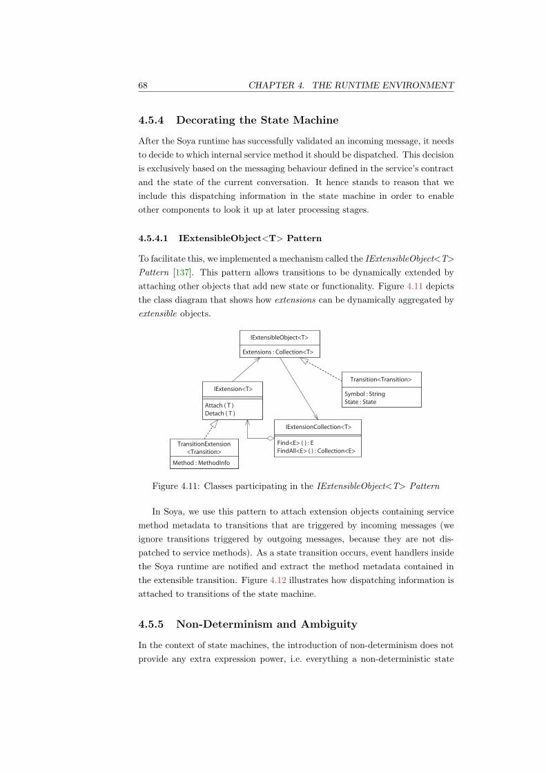
68 CHAPTER 4. THE RUNTIME ENVIRONMENT
4.5.4 Decorating the State Machine
After the Soya runtime has successfully validated an incoming message, it needsto decide to which internal service method it should be dispatched. This decisionis exclusively based on the messaging behaviour defined in the service’s contractand the state of the current conversation. It hence stands to reason that weinclude this dispatching information in the state machine in order to enableother components to look it up at later processing stages.
4.5.4.1 IExtensibleObject<T> Pattern
To facilitate this, we implemented a mechanism called the IExtensibleObject<T>Pattern [137]. This pattern allows transitions to be dynamically extended byattaching other objects that add new state or functionality. Figure 4.11 depictsthe class diagram that shows how extensions can be dynamically aggregated byextensible objects.
Detach ( T )
IExtensibleObject<T>
Extensions : Collection<T>
IExtension<T>
Attach ( T )
TransitionExtension
<Transition>
Method : MethodInfo
IExtensionCollection<T>
Find<E> ( ) : E
FindAll<E> ( ) : Collection<E>
Transition<Transition>
Symbol : String
State : State
Figure 4.11: Classes participating in the IExtensibleObject<T> Pattern
In Soya, we use this pattern to attach extension objects containing servicemethod metadata to transitions that are triggered by incoming messages (weignore transitions triggered by outgoing messages, because they are not dis-patched to service methods). As a state transition occurs, event handlers insidethe Soya runtime are notified and extract the method metadata contained inthe extensible transition. Figure 4.12 illustrates how dispatching information isattached to transitions of the state machine.
4.5.5 Non-Determinism and Ambiguity
In the context of state machines, the introduction of non-determinism does notprovide any extra expression power, i.e. everything a non-deterministic state
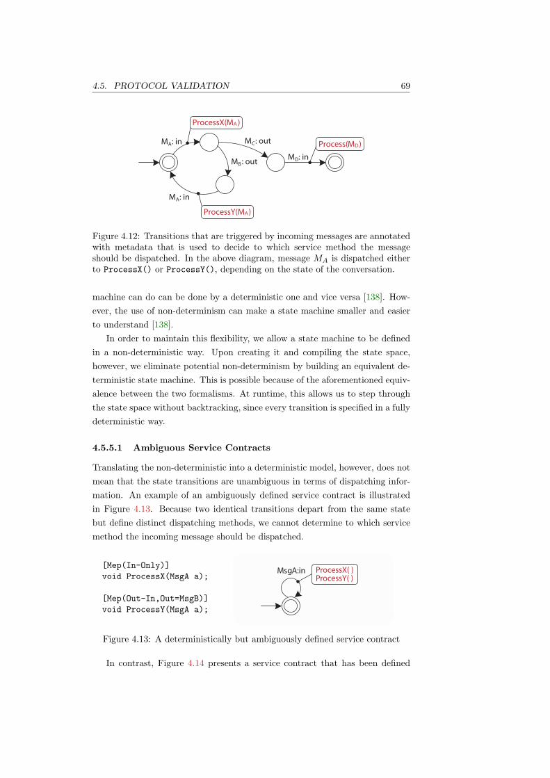
4.5. PROTOCOL VALIDATION 69
AM : in
MProcessX( )A
DB
CAM : in M : out
M : outM : in
MD
MProcessY( )A
Process( )
Figure 4.12: Transitions that are triggered by incoming messages are annotatedwith metadata that is used to decide to which service method the messageshould be dispatched. In the above diagram, message MA is dispatched eitherto ProcessX() or ProcessY(), depending on the state of the conversation.
machine can do can be done by a deterministic one and vice versa [138]. How-ever, the use of non-determinism can make a state machine smaller and easierto understand [138].
In order to maintain this flexibility, we allow a state machine to be definedin a non-deterministic way. Upon creating it and compiling the state space,however, we eliminate potential non-determinism by building an equivalent de-terministic state machine. This is possible because of the aforementioned equiv-alence between the two formalisms. At runtime, this allows us to step throughthe state space without backtracking, since every transition is specified in a fullydeterministic way.
4.5.5.1 Ambiguous Service Contracts
Translating the non-deterministic into a deterministic model, however, does notmean that the state transitions are unambiguous in terms of dispatching infor-mation. An example of an ambiguously defined service contract is illustratedin Figure 4.13. Because two identical transitions depart from the same statebut define distinct dispatching methods, we cannot determine to which servicemethod the incoming message should be dispatched.
[Mep(In-Only)]void ProcessX(MsgA a);
[Mep(Out-In,Out=MsgB)]void ProcessY(MsgA a);
MsgA:in ProcessX( )ProcessY( )
Figure 4.13: A deterministically but ambiguously defined service contract
In contrast, Figure 4.14 presents a service contract that has been defined
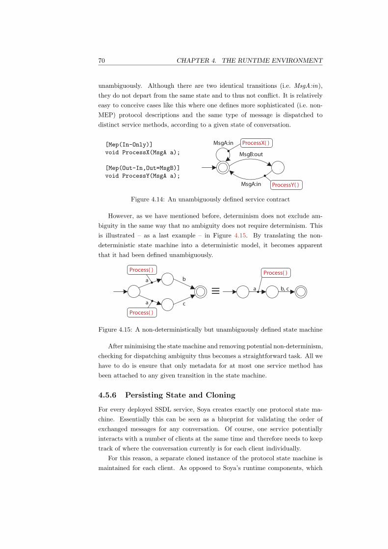
70 CHAPTER 4. THE RUNTIME ENVIRONMENT
unambiguously. Although there are two identical transitions (i.e. MsgA:in),they do not depart from the same state and to thus not conflict. It is relativelyeasy to conceive cases like this where one defines more sophisticated (i.e. non-MEP) protocol descriptions and the same type of message is dispatched todistinct service methods, according to a given state of conversation.
[Mep(In-Only)]void ProcessX(MsgA a);
[Mep(Out-In,Out=MsgB)]void ProcessY(MsgA a);
MsgA:in
MsgB:out
MsgA:in
ProcessX( )
ProcessY( )
Figure 4.14: An unambiguously defined service contract
However, as we have mentioned before, determinism does not exclude am-biguity in the same way that no ambiguity does not require determinism. Thisis illustrated – as a last example – in Figure 4.15. By translating the non-deterministic state machine into a deterministic model, it becomes apparentthat it had been defined unambiguously.
a
a
b
c
a
Process( )
Process( )
Process( )
b, c
Figure 4.15: A non-deterministically but unambiguously defined state machine
After minimising the state machine and removing potential non-determinism,checking for dispatching ambiguity thus becomes a straightforward task. All wehave to do is ensure that only metadata for at most one service method hasbeen attached to any given transition in the state machine.
4.5.6 Persisting State and Cloning
For every deployed SSDL service, Soya creates exactly one protocol state ma-chine. Essentially this can be seen as a blueprint for validating the order ofexchanged messages for any conversation. Of course, one service potentiallyinteracts with a number of clients at the same time and therefore needs to keeptrack of where the conversation currently is for each client individually.
For this reason, a separate cloned instance of the protocol state machine ismaintained for each client. As opposed to Soya’s runtime components, which

4.6. MESSAGE DISPATCHING 71
are stateless, the state of the protocol state machine needs to be maintainedacross multiple message exchanges. For that reason, each conversation has aseparate state machine associated with its session context. However, ratherthan duplicating the entire state space for each client, only the reference to thecurrent state position needs to be copied.
This allows for a convenient programming abstraction, because every clientappears to have its own state machine. At the same time, it does not increase thememory footprint unnecessarily, consequently allowing the runtime to handlemany clients concurrently.
Similarly, if we want to persist the state of conversations into a relationaldatabase, for example, we only need to persist the blueprint (i.e. the originalstate machine instance) and one reference per client to the current state5.
4.6 Message Dispatching
4.6.1 State-Based Method Selection
In SSDL the concept of operations or service invocations does not exist and it isexpected that applications reason about message content and ordering in orderto derive appropriate actions.
Of course, since Soya-based services are built using an object-oriented pro-gramming language, a local API method is ultimately invoked. Soya processesincoming messages and decides to which internal method they should be dis-patched. This decision is exclusively based on the service’s protocol and thecurrent state of the conversation (i.e. the protocol state machine). Methodnames, however, play no role in this decision-making process. In consequence,this implies that multiple arrivals of the same kind of message can actually bedispatched to different methods.
Although not being able to capture more than two consecutive messagesmakes the MEP SSDL protocol framework a poor candidate for demonstratingstate-based method selection, it can still be used to illustrate the concept. Fig-ure 4.16 shows two methods for processing the same kind of incoming messages.ProcessX() is invoked when an unsolicited message of the given type is re-ceived. In contrast, ProcessY() is only invoked when the service has previouslysent an outgoing message of type MsgB. The right part of the figure, shows thestate machine that is inferred from the protocol definition. Each method on theleft may contain application logic that does something different based on theconversation state.
5The current Soya release 0.1 provides only an in-memory storage facility.

72 CHAPTER 4. THE RUNTIME ENVIRONMENT
[Mep(In-Only)]public void ProcessX(MsgA a) {/* application logic */
}
[Mep(Out-In,Out=MsgB)]public void ProcessY(MsgA a) {/* application logic */
}
MsgA:in
MsgB:out
MsgA:in
X Y
Figure 4.16: State machine inferred from protocol metadata. X and Y standfor the methods ProcessX() and ProcessY(), respectively, to which MsgA willbe dispatched.
Without protocol metadata, the two methods in Figure 4.16 would be am-biguous. In fact, a service developer would need to write application code todistinguish between the two cases, which we understand might impose a signif-icant burden on the developer. Therefore, Soya takes advantage of the protocolmetadata to decide to which methods messages need to be dispatched. Present-ing the developer with this abstraction removes confusion as what needs to beimplemented.
4.6.1.1 Using the Protocol State Machine Decoration
In Section 4.5.4 we have explained how dispatching information is added to theprotocol state machine. Every time a state transition is performed, the protocolstate machine additionally fires an event that contains transition-related data,including potential dispatching information. As a result, other runtime classescan subscribe to these events and obtain dispatching data. Later, they use thisdata to invoke application logic and dispatch the message.
4.6.2 Asynchronous Operation Invocation
SSDL models interactions between services purely as a collection of exchangedone-way messages. Indeed, messages are related only through defined messagingbehaviour and correlated by content and conversation state, not operation se-mantics. This is facilitated by WS-Addressing header blocks inside the messagesand middleware that keeps track of the exchanged messages.
Every actual service invocation thus happens asynchronously, allowing clientsto regain control over the connection immediately after the message has beenvalidated and dispatched to the application logic (i.e. the service). Essentially,this decouples the messaging behaviour from operation semantics.
If a client still wants a synchronous interaction behaviour with the service,it can of course block and wait for a correlated message to be returned. This

4.6. MESSAGE DISPATCHING 73
is a purely local programming decision and does not affect the messages on thewire [139].
4.6.2.1 Decoupling Transport Bindings
SOAP transport bindings, however, may impose temporal constraints on themessage exchange. The HTTP binding, for example, requires that in-out mes-sage exchange patterns are mapped to HTTP request-response operations. How-ever, we cannot generally determine when or if a service sends back a response.Consequently, we do not wait for the application logic to finish processing,but instead immediately return an empty HTTP 200 - OK response back to theclient, acknowledging that the message has been successfully received and dis-patched to the service. Some undefined time later (i.e. seconds or days), theservice might send a message back. To do so, a new HTTP request that includesthe response message data is created.
If we used SMTP instead, the behaviour at the transport level would be dif-ferent, because there would be no requirement to send a transport-level responseto the initial request. At the service-level, however, this change of transport pro-tocols is completely transparent. This behaviour is illustrated in Figure 4.17.
4.6.2.2 Decoupling Temporal Constraints
By internally calling service methods asynchronously, we also effectively de-couple the application logic from temporal constraints imposed by transportbindings, because the semantics of the transport infrastructure are no longercoupled to service operations. Indeed, this practice allows us to reuse a widelydeployed transport infrastructure (i.e. HTTP) without imposing the semanticsof that infrastructure onto message-oriented services. Further, it has the positiveside-effect that Soya inherently supports long-running interactions.
4.6.2.3 Dealing with Infrastructure and Application Errors
Nevertheless, the fact that the client service does not care about the result of aone-way invocation does not mean that it does not care if the invocation tookplace at all. In fact, if an application requires reliability, additional mecha-nisms such as, for example, WS-ReliableMessaging [140] should be used, evenfor one-way messaging. To understand this better, we found it useful to distin-guish between errors that can occur in infrastructure and errors that occur inapplication logic.
Errors occurring in the infrastructure can range from connection problemsto protocol validation errors. These kind of errors need to be communicated tothe clients (or their middleware), so they will be aware that a given message has

74 CHAPTER 4. THE RUNTIME ENVIRONMENT
Client Soya Service
Processing
Incoming
Message
Preparing
Outgoing
Message
HTTP 200 Response (empty)
HTTP Request
HTTP Request
HTTP Response (empty)
Async Invoke
“Callback”
Figure 4.17: The application logic is invoked asynchronously and decoupledfrom the used transport protocol.
never reached the service. Using the HTTP example again, we could for examplereturn a HTTP 5xx - Server Error response, indicating that the message hasnot been processed.
Errors that occur in the application logic, on the other hand, need to behandled by the application. For example, by sending appropriate error messagesto the client that indicate what went wrong. These kind of error messages,however, are part of the normal application flow. In fact, they are part of theservice contract and hence even subject to be validated by the runtime.
The following example helps illustrating these concepts: A client sends aCancelOrderMsg to the service and does not care about the result of the invo-cation, assuming that no further actions need to be taken. The first time, theclient receives a HTTP 301 - Moved Permanently response from the service,saying that the URI of the service has changed and the message has not beendelivered. The client thus updates the remote endpoint address and re-sendsthe message to the new URI. This time the message is dispatched to the ser-vice successfully, which acknowledges this with a HTTP 200 response and closesthe connection. In the meantime, however, the service application processesthe message and finds that the order cannot be cancelled. It therefore sends anew HTTP request to the client (address is taken from WS-Addressing ReplyToheader) containing an application error message along the lines of OrderAlready-

4.7. METADATA GENERATION AND EXPOSURE 75
ShippedMsg.This example illustrates that the latter kind of errors are part of the normal
application flow and thus should not be handled by middleware infrastructure,whereas the former should.
4.7 Metadata Generation and Exposure
It is essential that a service exposes its contract, so that other services can derivehow to interoperate with it or reason about it. Upon creating the runtime, Soyabuilds an internal model that is subsequently used by its runtime components(see Section 4.8). This model represents different aspects of the service and itscontract. Although it cannot be exposed directly, it contains all the informationneeded to generate SSDL contracts. Consequently, Soya used it to generateXML infoset [132], which in turn can be serialised into XML and published asa SSDL contract.
The way this metadata (i.e. SSDL contract) can be retrieved is via HTTPand the ?ssdl convention. A client basically sends an HTTP GET request tothe base address where the service is located and appends the ssdl parameter tothe request URL. In turn, Soya sends back a HTTP response that contains XMLdata representing the SSDL contract. This process is illustrated in Figure 4.18.
Client
Soya Runtime
Infoset
Builder
HT
TP
En
dp
oin
t
Model
HTTP GET + /?ssdl
SSDL / XML
build
use
XML Infoset
Figure 4.18: Metadata is retrieved using HTTP and the ?ssdl convention.
4.8 Building the Runtime
The creation and configuration of both WCF and Soya runtimes is triggeredby deploying a service implementation to a SoyaServiceHost (see Section 3.7).On the one hand, the custom Soya host coordinates the creation of an internalservice model for subsequent use by runtime components. On the other hand, itconfigures WCF runtime parameters and replaces default implementations withcustom runtime logic (which we have discussed throughout this chapter).
Building the runtime involves the following activities, which are also illus-trated graphically in Figure 4.19:
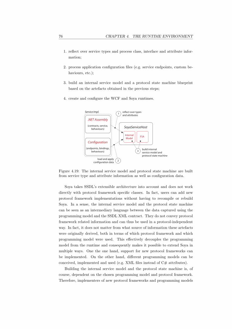
76 CHAPTER 4. THE RUNTIME ENVIRONMENT
1. reflect over service types and process class, interface and attribute infor-mation;
2. process application configuration files (e.g. service endpoints, custom be-haviours, etc.);
3. build an internal service model and a protocol state machine blueprintbased on the artefacts obtained in the previous steps;
4. create and configure the WCF and Soya runtimes.
Service Impl.
2
reflect over types
and attributes
load and apply
configuration data
1
build internal
service model and
protocol state machine
3
.NET Assembly
SoyaServiceHost(contracts, service,
behaviours)
Internal
ModelFSA
(endpoints, bindings,
behaviours)
Configuration
Figure 4.19: The internal service model and protocol state machine are builtfrom service type and attribute information as well as configuration data.
Soya takes SSDL’s extensible architecture into account and does not workdirectly with protocol framework specific classes. In fact, users can add newprotocol framework implementations without having to recompile or rebuildSoya. In a sense, the internal service model and the protocol state machinecan be seen as an intermediary language between the data captured using theprogramming model and the SSDL XML contract. They do not convey protocolframework related information and can thus be used in a protocol-independentway. In fact, it does not matter from what source of information these artefactswere originally derived, both in terms of which protocol framework and whichprogramming model were used. This effectively decouples the programmingmodel from the runtime and consequently makes it possible to extend Soya inmultiple ways. One the one hand, support for new protocol frameworks canbe implemented. On the other hand, different programming models can beconceived, implemented and used (e.g. XML files instead of C# attributes).
Building the internal service model and the protocol state machine is, ofcourse, dependent on the chosen programming model and protocol framework.Therefore, implementers of new protocol frameworks and programming models

4.8. BUILDING THE RUNTIME 77
must provide the logic for building an internal service model and protocol statemachine.
4.8.1 Building the Internal Service Model
As suggested above, the creation of the internal model is dependent on thechosen protocol framework or programming model. As a result, the logic tobuild the model is delegated and encapsulated in specific classes. These classesmust implement interfaces, which represent common abstractions. Decouplingspecific implementations from runtime creation or execution logic is achievedusing the Abstract Factory Pattern [29] as illustrated in Figure 4.20. Decidingwhich IProtocolFactory to use is done automatically at runtime based on thechosen programming model and configuration parameters.
CreateProtocol ( )CreateStateMachine ( )
IProtocolFactory
CreateProtocol ( )CreateStateMachine ( )
MepProtocolFactory
CreateProtocol ( )CreateStateMachine ( )
ScProtocolFactory
Build ( Type )
Protocol
IProtocolBuilder
ScProtocolBuilder MepProtocolBuilder
creates
BuildDescription ( Type )AddEndpoint ( ServiceEndpoint )
Ssdl
SsdlDescriptionBuilder
uses
FaultsMessages
Infoset
IProtocol
MepProtocol ScProtocol
builds builds
uses
Figure 4.20: Protocol (in)dependent model creation
4.8.2 Building the Protocol State Machine
The protocol state machine is built in a similar manner to the way the internalservice model is created. Programming model and configuration data determinewhich IProtocolFactory implementation should be used, which in turn is usedto create specific IStateMachineBuilder instances. These classes build state ma-chines based on protocol information defined in IProtocol instances. Of course,the implementation of protocol and state machine builders must be provided ina consistent way as a family of classes. The MepStateMachineBuilder, for ex-

78 CHAPTER 4. THE RUNTIME ENVIRONMENT
ample, checks if a given IProtocol is indeed of type MepProtocol before it triesto start building the state machine. Figure 4.21 shows the class diagram of theclasses involved in creating state machines.
CreateProtocol ( )CreateStateMachine ( )
IProtocolFactory
CreateProtocol ( )CreateStateMachine ( )
MepProtocolFactory
CreateProtocol ( )CreateStateMachine ( )
ScProtocolFactory
Build ( IProtocol )
StateMachine
IStateMachineBuilder
ScStateMachineBuilder MepStateMachineBuilder
creates
uses
builds builds
uses
TransitionEvent
StateMachine
StateMachine (State)
Step (string)
CanStep (string) : bool
IsAccepted ( ) : bool
Reset ( )
SoyaRuntime
Figure 4.21: Building the Protocol State Machine
Chapter 5
Case Study
} Placet experiri. ~
— Thomas Mann
This chapter presents a case study in the creation of a service-oriented systemin connection with the Australian lending industry. The services composingthe application use an open standard for exchanging data and thus facilitatetransactions between lending institutions and valuation firms. We specificallystudied two cases of the application and showed how they can be realised withthe aid of Soya and SSDL. On the one hand, this enabled us to validate theusability of Soya’s programming model and the proper functioning of its runtimeenvironment. On the other hand, it deepened our understanding of to whatextent SSDL fosters the creation, description and execution of Web Services.Finally, by implementing a realistic reference case we did not only verify theapplicability of the practices under consideration but also discovered new needsthat would possibly have otherwise been missed.
5.1 Motivation and Background
In the Australian lending industry, processes such as property valuation are stilltedious tasks. A lot of the communication is carried out manually using mail,fax or telephone. A simple task like changing an incorrectly submitted propertyaddress can take up to three days and thus unnecessarily slow down the entirevaluation process. Because of the low degree of automation, a large number ofstaff is needed to process tasks which are of a predominantly mechanical nature.Other issues include bad communication between lenders and valuation firms,such as lenders not being informed by valuers of delays in processing a request.
79
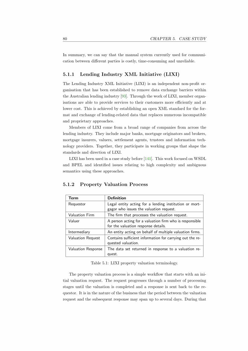
80 CHAPTER 5. CASE STUDY
In summary, we can say that the manual system currently used for communi-cation between different parties is costly, time-consuming and unreliable.
5.1.1 Lending Industry XML Initiative (LIXI)
The Lending Industry XML Initiative (LIXI) is an independent non-profit or-ganisation that has been established to remove data exchange barriers withinthe Australian lending industry [93]. Through the work of LIXI, member organ-isations are able to provide services to their customers more efficiently and atlower cost. This is achieved by establishing an open XML standard for the for-mat and exchange of lending-related data that replaces numerous incompatibleand proprietary approaches.
Members of LIXI come from a broad range of companies from across thelending industry. They include major banks, mortgage originators and brokers,mortgage insurers, valuers, settlement agents, trustees and information tech-nology providers. Together, they participate in working groups that shape thestandards and direction of LIXI.
LIXI has been used in a case study before [141]. This work focused on WSDLand BPEL and identified issues relating to high complexity and ambiguoussemantics using these approaches.
5.1.2 Property Valuation Process
Term Definition
Requestor Legal entity acting for a lending institution or mort-gagor who issues the valuation request.
Valuation Firm The firm that processes the valuation request.
Valuer A person acting for a valuation firm who is responsiblefor the valuation response details.
Intermediary An entity acting on behalf of multiple valuation firms.
Valuation Request Contains sufficient information for carrying out the re-quested valuation.
Valuation Response The data set returned in response to a valuation re-quest.
Table 5.1: LIXI property valuation terminology.
The property valuation process is a simple workflow that starts with an ini-tial valuation request. The request progresses through a number of processingstages until the valuation is completed and a response is sent back to the re-questor. It is in the nature of the business that the period between the valuationrequest and the subsequent response may span up to several days. During that

5.2. APPROACH 81
time requestors, intermediaries and valuation firms can still communicate witheach other by sending messages in either direction. This includes querying andsending updates of the valuation request’s status, cancelling the request, re-negotiating the fees and so forth. Further, the actual processing of the messagesoften still depends on human activities, such as a manager accepting or rejectinga fee change, a valuer entering valuation data after inspecting a property, etc.
Throughout its lifecycle, a valuation request progresses through several dif-ferent processing stages. Each stage is defined by LIXI and has a status codethat can be used to indicate at which stage a valuation request is within thisprocessing cycle. This is illustrated in Figure 5.1. The corresponding workflow,however, is implemented by a service internally and does therefore not affectthe protocol directly.
1. Instructed
2. Accepted
10. Cancelled
3. Assigned 4. InProgress 5. Inspected 7. Completed6. Awaiting
Authorisation
9. Amendment
Required
8. Finalised 11. Delayed
Figure 5.1: The lifecycle of a valuation request.
5.2 Approach
The two cases that we studied involved a number of Web Services that commu-nicated with each other by exchanging some predefined messages according toa business protocol. Although the two cases had many common characteristics,they differed from each other in terms of the business protocol’s complexity andthe number of involved parties. Notwithstanding, our focus and method differedfor each case. During the first case, we concentrated on Soya’s programmingmodel and its runtime behaviour. To do so, we created an executable implemen-tation of the services. Although we captured the protocol using the MEP proto-col framework, we were still able to investigate the runtime in a generic way, as aresult of its protocol framework independence (see Section 4.8). The focus of thesecond case was to establish if SSDL’s other protocol frameworks, specificallySequencing Constraints (SC) [98], were powerful enough to express the givenbusiness protocol. Because the development process was the same as in theprevious case, we concentrated solely on the protocol description. Since Soya’sprogramming model does currently only support the MEP protocol framework,

82 CHAPTER 5. CASE STUDY
we modelled the protocol description directly in XML. Further, we re-modelledthe service description including protocol information using WSDL and BPELand compared the results.
In general, we aimed at establishing if Soya and SSDL could be used tocreate the given application and if their use implied significant benefits or draw-backs compared to incumbent approaches. Further, we wanted to find out ifSoya and SSDL were sufficiently expressive to capture the relevant aspects ofour services; how much effort was required in creating them; if the developedtechnical solution aligned well with the business case; if employing Soya andSSDL naturally lead to service-oriented application design.
5.3 Case One: Property Valuation
5.3.1 Focus
The target of the first case in our study was primarily Soya’s programmingmodel and runtime environment. Not only did we want to establish if theoffered programming abstractions could be used to create the given application,but also if they facilitated the development process and fostered service-orienteddesign. Further, we wanted to affirm that Soya’s runtime behaviour includingmessage processing, contract enactment, dispatching and so forth worked asexpected.
5.3.2 Case Description
Our first case involved a requestor that communicated directly with a valuationfirm. An example of a typical communication between the two services is shownas a sequence diagram in Figure 5.2. First, the requestor sends a valuation re-quest to the valuation firm. Then, after automatically performing some validitychecks on the incoming request, the valuation firm assigns it to one of its em-ployees. After the employee has been notified, she decides that the requested feeis not adequate. She hence delays the valuation request and sends a fee changerequest back to the requestor. The requestor, however, does not accept the feechange request. Therefore, the valuation firm sends yet another fee change re-quest, which is accepted by the requestor this time and thus subsequently alsoby the valuation firm. After the successful fee-negotiation, the valuation firminforms somebody to have a look at the property and internally updates the sta-tus of the request to in-progress. Some days later, after the requestor still hasnot heard anything from the valuation firm, it sends a status enquiry regardingthe request. The valuation firm in turn replies that the valuation is inProgress.

5.3. CASE ONE: PROPERTY VALUATION 83
Finally, the valuer that inspected the property enters the valuation data intothe valuation firm’s system. Internally, this updates the status of the request toinspected. After all the valuation data has been entered, the system updates thestatus to completed and sends the valuation response to the requestor. Once theresponse has been sent, the status of the request is updated one more time tofinalised. On the requestor side, the service receives the valuation data, whichconcludes the conversation between the two services.
Status (Finalised)
Requestor Valuation Firm
Status (Assigned/Delayed)
Status (InProgress)
Status (Inspected/Completed)
Status (InProgress)
StatusRequest
FeeChangeAccepted
FeeChangeRequest
FeeChangeRequest
Status (Delayed)
FeeChangeRejected
ValuationResponse
Status (Accepted)
ValuationRequest
Figure 5.2: A typical conversation between a requestor and a valuation firm.
Of course, the described conversation is one of many such possible conversa-tions. Figure 5.3 represents the actual business protocol between requestor andvaluation firm in a more generic way as a state machine. Although the showndiagram represents the view of the incoming and outgoing messages from therequestor’s point of view, the valuation firm’s perspective can be derived bysimply inverting the direction attributes on the state transitions.
The protocol defines that the requestor sends an initial valuation request,which might or might not be acknowledged with a Status message. At thispoint, a number of possible interactions can happen. The requestor can, forexample, receive a FeeChangeRequest, which must be either accepted or rejected.Further, the requestor might enquire about the request’s status, in which casethe valuation firm must reply. Moreover, the valuation firm can send any numberof Status updates at arbitrary intervals. In addition, these interactions are all

84 CHAPTER 5. CASE STUDY
s’s
f
v
s
s’
f
f’
f’’
= StatusRequest
= Status
= FeeChangeRequest
= FeeChangeAccepted
= FeeChangeRejected
direction: in, out
v
v’
c
= ValuationRequest
= ValuationResponse
= ValuationCancelled f’, f’’
c, s’, v’ε, s’
Figure 5.3: The valuation business protocol from requestor’s perspective.
optional and may be repeated and intermixed in an arbitrary order. Finally,the conversation is terminated at some point, if either the requestor cancelsthe request, the valuation firm declines the request (this corresponds to the s’transition to the final state, because the firm actually sends a Status message)or if the inspection was performed successfully and a ValuationResponse is sentback to the requestor.
5.3.3 Protocol Translation
Before we could implement the business protocol, we needed to translate it intoa form that could be captured with the MEP protocol framework. Since thevaluation protocol was not available in a formal or machine-processable form,we had to do the transformations by hand. In fact, even the state machineshown in Figure 5.3 was derived manually from the LIXI specification. First,we identified the messages and their direction (i.e. the state transitions). Next,we correlated them into the MEPs shown in Table 5.2. Finally, we did thesame for the valuation firm, by simply inverting the direction attributes on thepatterns.
Pattern Messages
out-optional-in out: ValuationRequestMsg, in: StatusMsg
in-only in:StatusMsg
out-in out:StatusRequestMsg, in:StatusMsg
in-out in:FeeChangeRequestMsg, out:FeeChangeRejectedMsg
in-out in:FeeChangeRequestMsg, out:FeeChangeAcceptedMsg
in-only in:ValuationResponseMsg
out-only out:CancelValuationMsg
Table 5.2: Message exchange patterns derived from valuation process protocol.

5.3. CASE ONE: PROPERTY VALUATION 85
By combining the described MEPs into a state machine according to theirdefinition in Figure 4.7, we obtained the state machine depicted in Figure 5.4.Inevitably, some protocol information was lost in the translation process as aresult of the insufficient expression power of the MEPs. Consequently, messagescould have been dispatched in the course of a conversation that our applicationcode did not expect, because they were not specified. Similarly, our implemen-tation could have sent outgoing messages that did not adhere to the businessprotocol.
v’
v
s
s’ f
f’, f’’
s’
v, s’, c, v’
Figure 5.4: The actual protocol defined by the MEP patterns in Table 5.2.
The defined MEP protocol is hence just an approximation of the actualbusiness protocol (see Figure 5.5). As a matter of fact, it can easily be shownthat the implemented protocol is less restrictive than the original because itdoes not succeed in modelling the exclusion of all disallowed interactions. Forexample, it is possible that the requestor sends a StatusRequestMsg even thoughit has not sent a ValuationRequestMsg previously.
Implemented
Specified
Figure 5.5: Allowed interactions of business protocol compared to implementedMEP protocol.
The cause for this mismatch is the fact that the eight simple patterns de-fined in the MEP protocol framework were not sufficient to express the requiredbusiness protocol in an accurate manner. In fact, these patterns do not allowcapturing message exchanges that span more than two messages (one incomingand one outgoing). Therefore, we could not model the fact that a valuationrequest, for example, might be followed by some status and fee negotiationmessages and then by a valuation response, because it involved more than two

86 CHAPTER 5. CASE STUDY
messages.This is not a limitation of Soya’s programming model or SSDL per se, but a
restriction of the MEP protocol framework. As a matter of fact, we will see inthe second case of our study that other SSDL protocol frameworks can be usedto represent business protocols more accurately.
5.3.4 Development Process
5.3.4.1 Message Definition
All the messages that can be exchanged by the requestor and the valuationfirm were defined in an XML schema provided by LIXI. Instead of creating thedata contracts according to the schema manually, we used it to generate thedata contract classes using a configurable .NET [142] code generator. Althoughthe code generator produced acceptable results, we still had to make manualadjustments to the generated code. For example, it was not possible to specifythat a data member of a data contract should be serialised as an XML attribute,because the generator did not support this kind of XML projection. Thus,schemas that required the use of XML attributes were not supported per se.The following simple LIXI XML schema element, for example, could not berepresented as a data contract, because it defined an XML attribute:
<xs:complexType name="PropertyType">
<xs:attribute name="Name" use="required" type="xs:string"/>
</xs:complexType>
Nevertheless, the generator could be configured to output types that use acustom formatting implementation for serialisation and deserialisation. Conse-quently, these types could store anything that could be represented in XML.Although this solved the XML attribute problem, the generated code was notparticularly useful for our application because it was too generic. In fact, byinferring XML schema from the generated type, we obtained a schema thatrepresented the XML schema type anyType.
For this reason, we introduced a strongly typed member that represented theXML attribute and provided a custom implementation for reading and writingto and from XML respectively. Further, we implemented a method that loadedthe XML schema for the implemented type according to its definition in the LIXIschema. By using the described approach we achieved the required mapping.Indeed, this method is very powerful in general and can be used to representeven the most complex XML data structures.
After generating the data contracts, we created the message contracts. Un-like generating the former, there was no support for creating the latter from

5.3. CASE ONE: PROPERTY VALUATION 87
an XML schema. Therefore, we created the message contracts manually. SinceLIXI did not define its messages with respect to SOAP (i.e. headers and bod-ies), we included the defined LIXI messages without modification in the bodyof the message contracts. Furthermore, we included the valuation request idin the header of most message contracts, so that it would be transmitted inthe SOAP header in addition to the main payload in the SOAP body. On theapplication-level this allowed us to correlate incoming messages with the respec-tive valuation request. Correlating messages into one continuous conversation,however, was not done using this application header but automatically handledby Soya through means of WS-Addressing headers. Nevertheless, we found ituseful to have direct access to the valuation request id and by putting it in theSOAP header, we did not have to change the LIXI XML schema. Since weonly had to create eight message classes, the associated effort was insignificant.Yet given the simple but tedious nature of the task, we hold the opinion that itwould be useful to write a small code generator if more classes needed to be gen-erated. At the same time, this would also help keeping the classes synchronisedwith the XML schema.
5.3.4.2 Protocol Definition
Because we had translated the protocol into MEPs earlier, we only needed toapply them as C# attributes to the service contract. This process was relativelystraightforward as we just defined service operations for processing incomingmessages and decorated them with the protocol metadata. While creating theservice interface and the attributes, we were able to focus solely on the servicecontract. As a result, we did not have to be concerned about implementationdetails such as, for example, operation names. Figure 5.6 shows the requestor’sservice contract.
The top-most attribute declares that a CancelValuationMsg can be sent atany time. It is attached directly to the interface because it is an OutOnlyattribute and hence does not require an associated method for processing anincoming message. The metadata attached to the first method defines that aStatusMsg can be received in an unsolicited manner (InOnly), compulsorily inresponse to a StatusRequestMsg (OutIn) or optionally in response to a Valua-tionRequestMsg (OutOptionalIn). The attributes on the second method statethat a FeeChangeRequestMsg can be received at any time but must be followedby an outgoing FeeChangeAcceptedMsg or FeeChangeRejectedMsg. Finally, thelast method defines that a ValuationResponseMsg can be received at any time.

88 CHAPTER 5. CASE STUDY
[Mep(Style=MepStyle.OutOnly, Out=typeof(CancelValuationMsg))]
public interface IRequestorService {
[Mep(Style=MepStyle.InOnly)]
[Mep(Style=MepStyle.OutIn, Out=typeof(StatusRequestMsg))]
[Mep(Style=MepStyle.OutOptionalIn, Out=typeof(ValuationRequestMsg))]
void Process(StatusMsg msg);
[Mep(Style=MepStyle.InOut, Out=typeof(FeeChangeAcceptedMsg))]
[Mep(Style=MepStyle.InOut, Out=typeof(FeeChangeRejectedMsg))]
void Process(FeeChangeRequestMsg msg);
[Mep(Style=MepStyle.InOnly)]
void Process(ValuationResponseMsg msg);
}
Figure 5.6: The service contract specified using Soya’s programming model andthe MEP protocol framework.
5.3.4.3 Contract Implementation
Subsequently, we implemented the defined service interface. In our case study,the requestor and valuation firm both used humans to process the requestsand only a small part of the entire process was actually handled automatically.Apart from storing and retrieving valuation requests to and from the data tier,our service implementation therefore mainly delegated the requests by sendingnotifications to employees. The employees in turn interacted with the systemthrough interactive user interfaces.
Both sides used Soya’s client API to send messages. In case the requestwas processed automatically (e.g. a status query), the service implementationhandled the request automatically and potentially sent a response immediatelyfrom within the service method. This is illustrated in the following examplewhich shows how a status request that is handled automatically by the valuationfirm:
public void Process(StatusRequestMsg msg) {
string id = msg.StatusRequest.Id;
ValuationRequest req = ValuationRequestDAO.Instance.Load(id);
SoyaServiceHost.Reply(Commons.ConvertToMsg(new StatusMsg(req.Status)));
}
If, however, the service operation required human interaction, we normallypersisted the client for future reference and in order to free resources. Later, itwas loaded back into memory again and used to continue existing conversationsand send outgoing messages. This is illustrated in the following code snippet,which sends the valuation response to the requestor, after all the data had beenentered by a valuer:
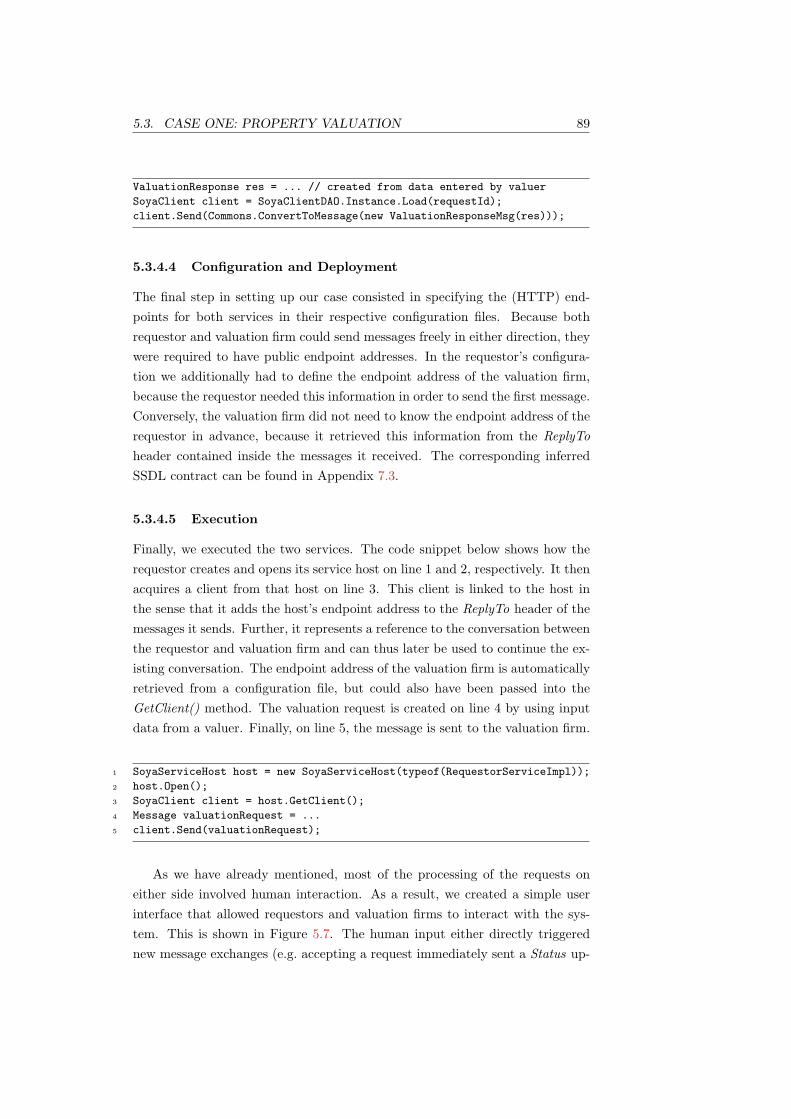
5.3. CASE ONE: PROPERTY VALUATION 89
ValuationResponse res = ... // created from data entered by valuer
SoyaClient client = SoyaClientDAO.Instance.Load(requestId);
client.Send(Commons.ConvertToMessage(new ValuationResponseMsg(res)));
5.3.4.4 Configuration and Deployment
The final step in setting up our case consisted in specifying the (HTTP) end-points for both services in their respective configuration files. Because bothrequestor and valuation firm could send messages freely in either direction, theywere required to have public endpoint addresses. In the requestor’s configura-tion we additionally had to define the endpoint address of the valuation firm,because the requestor needed this information in order to send the first message.Conversely, the valuation firm did not need to know the endpoint address of therequestor in advance, because it retrieved this information from the ReplyToheader contained inside the messages it received. The corresponding inferredSSDL contract can be found in Appendix 7.3.
5.3.4.5 Execution
Finally, we executed the two services. The code snippet below shows how therequestor creates and opens its service host on line 1 and 2, respectively. It thenacquires a client from that host on line 3. This client is linked to the host inthe sense that it adds the host’s endpoint address to the ReplyTo header of themessages it sends. Further, it represents a reference to the conversation betweenthe requestor and valuation firm and can thus later be used to continue the ex-isting conversation. The endpoint address of the valuation firm is automaticallyretrieved from a configuration file, but could also have been passed into theGetClient() method. The valuation request is created on line 4 by using inputdata from a valuer. Finally, on line 5, the message is sent to the valuation firm.
1 SoyaServiceHost host = new SoyaServiceHost(typeof(RequestorServiceImpl));
2 host.Open();
3 SoyaClient client = host.GetClient();
4 Message valuationRequest = ...
5 client.Send(valuationRequest);
As we have already mentioned, most of the processing of the requests oneither side involved human interaction. As a result, we created a simple userinterface that allowed requestors and valuation firms to interact with the sys-tem. This is shown in Figure 5.7. The human input either directly triggerednew message exchanges (e.g. accepting a request immediately sent a Status up-

90 CHAPTER 5. CASE STUDY
date message) or was used as input in future message exchanges (e.g. filling invaluation response data).
Figure 5.7: Interactive console session between requestor (back) and valuationfirm (front).
5.3.5 Discussion
5.3.5.1 Simplicity & Development Effort
Because we were given an XML schema, we were able to generate the data con-tracts without significant effort. The only time-consuming task at this stage wasproviding a custom serialisation and deserialisation implementation for typesusing XML attributes, because the data contract generator was not able tohandle this situation. Unfortunately, the required effort for accomplishing thisrelatively simple and common task was disproportional. Considering that XMLattributes are an essential part of most XML documents, we think that appro-priate mechanisms for capturing them in data contracts or better tool supportfor generating source code should be provided in future. Still, the task wasmechanical to a considerable extent and we indeed believe that by leveragingthe generator, it could easily be automated. The same is true for creating themessage contract classes. It is a mechanical task and thus a good candidate forbeing executed by a code generator.
Applying the extracted patterns to the service contract using Soya’s pro-gramming model was again an almost mechanical task. We just had to look atthe extracted patterns and identify the set of incoming messages types. Thenwe wrote one service method signature for each distinct type and applied the

5.3. CASE ONE: PROPERTY VALUATION 91
MEP to it. In case two or more patterns shared the same input message type,we just added multiple MEP attributes to the service method in any order.Again, because of the mechanical and straightforward nature of this task, wethink that it could also be automated by a tool.
5.3.5.2 Service-Orientation
All through the development process, the main abstraction we were workingwith was the message. The data structures defined in LIXI were used as payloadin messages. The interaction protocol was defined using MEPs which in turnwere defined using messages. The service interface was defined using messages.And finally the data structures that our service implementation received andsent were messages. Therefore, we never had to give up this message-orientedperspective.
To contrast this with an operation-centric approach, we will consider twoexamples from our case study and compare how we would have implementedthem in an operation-centric solution. According to our protocol a StatusRe-questMsg must be followed by a StatusMsg. This corresponds to an in-out MEP.If we would correlate the message using operations, we could have defined anoperation like, for example, GetStatus(StatusRequestMsg msg) returning a Sta-tusMsg.
In the above case, this approach makes sense. Notwithstanding, it is limitedto these kind of simple scenarios. By looking at another part of the proto-col, we see that a FeeChangeRequestMsg must be responded to with either aFeeChangeAcceptedMsg or a FeeChangeRejectedMsg. Because this part of theprotocol can have two possible outcomes, we can no longer represent it using theoperation-abstraction. Although there are workarounds to this problem, theyhave disadvantages.
We could, for example, use a one-way operation and provide a callbackinterface through which we can send either of the two messages. Yet by doingthis, we are introducing a new API (the callback API) and mixing it with theoperation API. More importantly, we loose the information of what can actuallybe sent back after a FeeChangeRequestMsg has been received. This fact is nolonger visible from the service interface or description and hence requires bothservice developers and service consumers to know interaction semantics definedoutside the scope of the machine-processable format.
Another solution is to abstract the two return types into a common type (e.g.FeeChangeResponseMsg) and introduce an attribute that facilitates distinguish-ing between the two former types (e.g. type=accepted/rejected). As a result, wewould have only one response message type and could therefore map it to an

92 CHAPTER 5. CASE STUDY
operation. Unfortunately, this approach necessitates changing the LIXI XMLschema or creating an intermediary schema. Further, it requires additional codeinside the application logic that parses the message content in order to find outwhether it needs to execute the logic that is responsible for handling either anaccepted or a rejected fee change request.
In both solutions of the operation-centric approach, the changes made to theimplementation are propagated to the outside world and have an effect on theweb service’s contract (i.e. service description including XML schema), violatingservice encapsulation and service-oriented design principles.
Conversely, Soya and SSDL forced us to think only in terms of messageexchanges throughout the development process, which naturally led to a service-oriented design.
5.3.5.3 Soya Programming Model & Runtime
Soya’s programming model allowed us to express the complete MEP protocolwith 7 lines of code. Because the MEP attributes in Soya directly reflect allthe existing MEPs, we had no difficulties representing them in code. Whileimplementing the case for our study, however, we wanted the service to use theLIXI XML schema instead of using the one inferred from the data contracts. Ini-tially, this was not possible in Soya. As a result, we implemented this additionalfeature and added it to Soya’s codebase.
The runtime environment worked as expected. Upon deployment, the in-ferred SSDL contract reflected the MEPs that we had specified using the C#attributes and could be accessed via HTTP. The services communicated success-fully with each other via the specified endpoints. The incoming messages wereproperly validated against the schema and message definitions in the contractand dispatched to the correct local service methods.
5.3.5.4 MEP Protocol Framework
We mentioned that we formalised the business protocol into a state machinerepresentation. Although the MEP description could then be derived in a fairlydirect manner, it still was a manual trial and error process that did not followany formal schemes. It required us to mentally partition and re-think the pro-tocol into MEPs and therefore to translate a business protocol into a technicalrepresentation of it. The resulting description did therefore not only miss someaspects of the protocol, but was also dissimilar to the original.
5.4. CASE TWO: INTERMEDIARY 93
5.4 Case Two: Intermediary
5.4.1 Focus
In the previous section we have shown that Soya’s programming model simplifiedthe development process and that its runtime environment could be used toexecute SSDL-based services. Yet we also concluded that the MEP protocolframework was not expressive enough to model the given business protocol. Inthe case presented in this section we therefore wanted to establish if SSDL’s morepowerful Sequencing Constraints (SC) protocol framework [98] could representthe protocol more accurately.
Since the second case differed from the first only in terms of its businessprotocol, we focused solely on this aspect. Because Soya currently does notoffer mechanisms to capture SC protocols, we created the protocol descriptiondirectly in XML. Although this procedure did not directly involve Soya, it was animportant step in determining the future direction of both Soya and SSDL. Byshowing that SC can be used to model even complex protocols, we would havestrong reasons justifying the effort to implement direct programming supportfor this protocol framework in Soya.
Further, we re-implemented the given case using WSDL and BPEL in orderto compare it against SSDL and SC in terms of expressiveness, complexity, easeof use and service-orientation.
5.4.2 Case Description
Although the XML schema, the transferred messages, the business goal andso forth of the second case in our study was the same as before, the businessprotocol was more complex and involved an additional service party. The re-questor did not communicate with a valuation firm directly, but instead with anintermediary. The intermediary in turn communicated and negotiated with anarbitrary number of valuation firms. Based on the incoming request and somebusiness criteria, the intermediary selected the most appropriate valuation firmfrom a list of potential candidates. Because, ultimately, only one firm performedthe valuation, the intermediary had to ensure that it cancelled pending valuationrequests accordingly.
Figure 5.8 illustrates this scenario using an example. The requestor sendsa valuation request to the intermediary. Based on the incoming request (e.g.postcode, due date, etc.) the intermediary retrieves a list of potential valuationfirms from an internal source and forwards the request to each one. In thegiven example, the second valuation firm accepts the request immediately andthus gets the order. Nevertheless, at this point the valuation firms could have

94 CHAPTER 5. CASE STUDY
also sent requests back to the intermediary to re-negotiate the fees. Essentially,the possible message exchanges between intermediary and valuation firms arethe same as the ones in the previous section between requestor and valuationfirm. As soon as the intermediary receives the acceptance message, it cancelsthe other two pending requests with valuation firm one and three. Apart fromthe no longer present fee negotiation, the behaviour between the requestor andthe intermediary is also the same as in the previous section between requestorand valuation firm. Consequently, the requestor can, for example, send statusenquiries to the intermediary at any time. As soon as the intermediary receivesthe valuation response from the chosen valuation firm, it forwards it to therequestor, which concludes the conversation.
Status (...)
StatusRequest
ValuationResponse
Status (Accepted)
ValuationRequest
GetValuationFirms
ValuationRequest
CancelValuation
Requestor Intermediary Val. Firm 1
ValuationRequest
StatusRequest
Status(Accepted)
Status(...)
ValuationResponse
Val. Firm 2
ValuationRequest
CancelValuation
Val. Firm n
Figure 5.8: A typical conversation between a requestor, intermediary and anumber of valuation firms.
Modelling the illustrated scenario posed a number of challenges. First, theintermediary had to communicate with two different parties and hence distin-guish between conversations. Second, the interactions with the requestor andthe valuation firms were required to occur concurrently, but still demanded forsome level of synchronisation. Third, the intermediary needed to communicatewith multiple instances of valuation firms concurrently. Fourth, the number andphysical locations of the valuation firms had to be determined at runtime in adynamic fashion.
As a result, we could no longer clearly represent the interactions using a statemachine the way we did in the previous sections. Nevertheless, we abstracted

5.4. CASE TWO: INTERMEDIARY 95
and summarised the intermediary’s protocol in Figure 5.9. Essentially, the maindiagram represents the communication with the requestor. The red square boxin the middle stands for the interactions with the valuer. As we have justdescribed, these interactions run in parallel to the ones with the requestor.Additionally, an arbitrary number of these interactions can execute concurrently.
s’
v c, s’, v’
s’s
s’s
f
v
f’, f’’
c, s’, v’ε, s’
multiple instances
concurrent executionRequestor
Valuer
Figure 5.9: The intermediary’s protocol. The red box can fork an arbitrarynumber of state machines that run concurrently to the main one and each other.
5.4.3 Sequencing Constraints
As we can see, the intermediary’s interaction behaviour was rather complex.Surprisingly, the SC protocol framework allowed describing this behaviour ina fairly concise way. Unfortunately, however, it does not provide native sup-port for representing iterative structures, which required us to translate thesestructures into recursive representations.
5.4.3.1 Representing Cycles
In our first trial to model the cycles in the communication between the inter-mediary and a valuation firm, we used a multiple element. The semantics ofthis element are defined analogously to the Replication (written ! ) construct inπ-calculus [97]. Unfortunately, this implies that its children can occur a mul-tiple number of times in parallel [98], which leads to the state machine shownin Figure 5.10. As we can see, this is a different, and in fact less restrictivestate machine than the one defined by the business protocol. As it turned out,we could not use the multiple element for modelling the iterative structures be-cause several instances of a structure could have occurred concurrently and thuspotentially interleaved with each other in a capricious manner.
In our second attempt, we expressed the iterations using recursive references
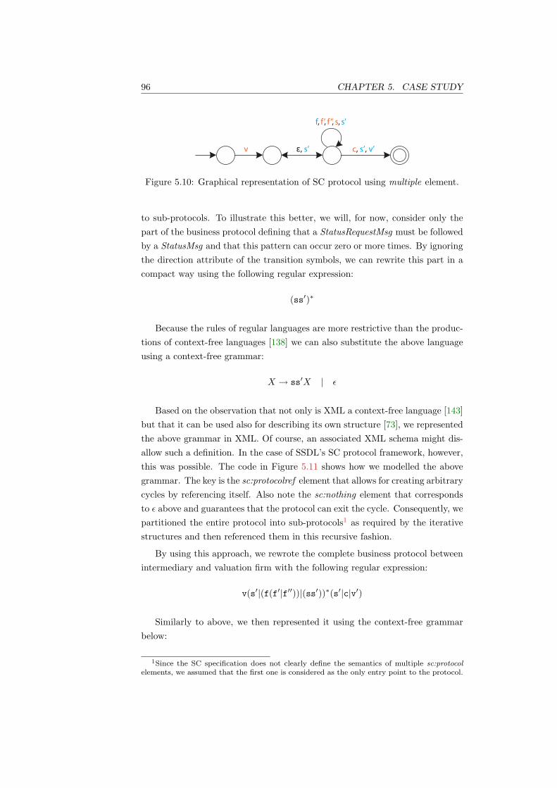
96 CHAPTER 5. CASE STUDY
v
f, f’, f’’, s, s’
ε, s’ c, s’, v’
Figure 5.10: Graphical representation of SC protocol using multiple element.
to sub-protocols. To illustrate this better, we will, for now, consider only thepart of the business protocol defining that a StatusRequestMsg must be followedby a StatusMsg and that this pattern can occur zero or more times. By ignoringthe direction attribute of the transition symbols, we can rewrite this part in acompact way using the following regular expression:
(ss′)∗
Because the rules of regular languages are more restrictive than the produc-tions of context-free languages [138] we can also substitute the above languageusing a context-free grammar:
X → ss′X | ε
Based on the observation that not only is XML a context-free language [143]but that it can be used also for describing its own structure [73], we representedthe above grammar in XML. Of course, an associated XML schema might dis-allow such a definition. In the case of SSDL’s SC protocol framework, however,this was possible. The code in Figure 5.11 shows how we modelled the abovegrammar. The key is the sc:protocolref element that allows for creating arbitrarycycles by referencing itself. Also note the sc:nothing element that correspondsto ε above and guarantees that the protocol can exit the cycle. Consequently, wepartitioned the entire protocol into sub-protocols1 as required by the iterativestructures and then referenced them in this recursive fashion.
By using this approach, we rewrote the complete business protocol betweenintermediary and valuation firm with the following regular expression:
v(s′|(f(f′|f′′))|(ss′))∗(s′|c|v′)
Similarly to above, we then represented it using the context-free grammarbelow:
1Since the SC specification does not clearly define the semantics of multiple sc:protocolelements, we assumed that the first one is considered as the only entry point to the protocol.

5.4. CASE TWO: INTERMEDIARY 97
<sc:protocol name="recurse">
<sc:choice>
<sc:sequence>
<ssdl:msgref ref="StatusRequestMsg" direction="out"/>
<ssdl:msgref ref="StatusMsg" direction="in"/>
</sc:sequence>
<sc:protocolref ref="recurse"/>
<sc:nothing/>
</sc:choice>
</sc:protocol>
Figure 5.11: A loop specified in the SC protocol framework.
X → vAB
A → A′A | ε
A′ → s′ | fA′′ | ss′
A′′ → f′ | f′′
B → s′ | c | v′
As we can see, A is defined recursively. We therefore defined a separateprotocol for that part. The protocol description that we obtained by translatingthe above grammar is depicted in Figure 5.12. Note that there are two separateprotocols (line 1 and 12). Further note the recursive calls on line 4 and 26.
5.4.3.2 Protocol Definition
After identifying and translating the iterative structures, we described the re-mainder of the protocol. Although the complete protocol is not listed in Fig-ure 5.13 due to its verbosity and similarity with previously presented parts, itcan be found in its entirety in Appendix 7.3. The keys in modelling the de-sired protocol were the sc:participant elements (abbr. sc:p) on line 1 and 2, thesc:parallel element on line 5 and the sc:multiple element on line 7.
The sc:participant element allowed us to distinguish between interactionswith the requestor and those with the valuation firms. The sc:parallel elementwas used to model that the intermediary and the requestor could communicateconcurrently to the conversations between the intermediary and the valuationfirms. This corresponded to the interactions that go to and from the red squarebox in Figure 5.9. Finally, the sc:multiple element made it possible to capturethe fact that the intermediary might have conversations with more than onevaluation firm at the same time.

98 CHAPTER 5. CASE STUDY
1 <sc:protocol name="intermediary-valuer">
2 <sc:sequence>
3 <ssdl:msgref ref="m:ValuationRequestMsg" direction="out"/>
4 <sc:protocolref ref="recurse"/>
5 <sc:choice>
6 <ssdl:msgref ref="StatusMsg" direction="in" />
7 <ssdl:msgref ref="CancelValuationMsg" direction="out" />
8 <ssdl:msgref ref="ValuationResponseMsg" direction="in" />
9 </sc:choice>
10 </sc:sequence>
11 </sc:protocol>
12 <sc:protocol name="recurse">
13 <sc:choice>
14 <ssdl:msgref ref="m:StatusMsg" direction="in" />
15 <sc:sequence>
16 <ssdl:msgref ref="m:FeeChangeRequestMsg" direction="out" />
17 <sc:choice>
18 <ssdl:msgref ref="m:FeeChangeAcceptedMsg" direction="in" />
19 <ssdl:msgref ref="m:FeeChangeRejectedMsg" direction="in" />
20 </sc:choice>
21 </sc:sequence>
22 <sc:sequence>
23 <ssdl:msgref ref="StatusRequestMsg" direction="out" />
24 <ssdl:msgref ref="StatusMsg" direction="in" />
25 </sc:sequence>
26 <sc:protocolref ref="recurse"/>
27 <sc:nothing/>
28 </sc:choice>
29 </sc:protocol>
Figure 5.12: The protocol between intermediary and valuation firm describedusing SC.
1 <sc:participant name="Req"/>
2 <sc:participant name="Val"/>
3 <sc:protocol name="Intermediary">
4 <ssdl:msgref ref="m:ValuationRequestMsg" direction="in" sc:p="Req"/>
5 <sc:parallel>
6 <!-- interactions with requestor -->
7 <sc:multiple>
8 <!-- interactions with valuation firm(s) -->
9 </sc:multiple>
10 </sc:parallel>
11 <sc:choice>
12 <ssdl:msgref ref="StatusMsg" direction="out" sc:p="Req"/>
13 <ssdl:msgref ref="CancelValuationMsg" direction="in" sc:p="Req"/>
14 <ssdl:msgref ref="ValuationResponseMsg" direction="out" sc:p="Req"/>
15 </sc:choice>
16 </sc:protocol>
Figure 5.13: The intermediary’s protocol captured using SC.

5.4. CASE TWO: INTERMEDIARY 99
While we modelled the above case, we observed two interesting aspects orpotential problems which are related to the communication with multiple val-uation firms. The first one was the positive realisation that we could describea protocol that involved a number of valuation firms which were not known atruntime. This is possible because at design-time, the contract is not bound toa particular valuation firm instance, i.e. a particular endpoint. Based on ourexperience with Soya and the features of current workflow engines [144] we cansafely assume that setting or modifying endpoint addresses at runtime can befacilitated by SSDL runtimes. Of course, the valuation firms must all adhere tothe same contract in terms of message types and their relative order of exchange,but their physical location is of no relevance to the contract per se. In fact, theSSDL specification does not define how physical endpoints should be mapped toparticipants. We therefore assumed that an SSDL implementation could mapone participant to multiple physical endpoints. In our case, the participant Valwould have been mapped to the endpoint addresses of valuation firm one, twoand three.
Unfortunately, however, the semantics of the sc:multiple element allowed itschildren to interleave with each other quite arbitrarily as we have already es-tablished earlier. Of course, on the one hand, this was exactly what we wanted(i.e. having conversations with multiple valuation firms at the same time) andassumed that middleware would take care of this, by distinguishing among con-versations with different valuation firms. On the other hand, the mentioned el-ement also allowed multiple concurrent invocations within a single conversationwith one valuation firm. Consequently, some interleaving could have occurred.Essentially, this was the same problem that we encountered in the previous sec-tion and solved using the recursive sc:protocolref call. Yet in this case this wasnot possible, because in addition to modelling the loop, its iterations actuallyhad to take place at the same time in parallel.
5.4.4 Discussion
Despite the SC protocol framework’s lightweight and small choice of constructs,we succeeded in modelling all the aspects of the given business protocol to asatisfactory degree. The procedure to obtain the final protocol description, how-ever, involved some effort. First, translating the iterative structures into theirrespective recursive representations did not only require re-thinking and addi-tional development effort, but also resulted in a description that was dissimilarand less readable than the original. We believe that the protocol descriptioncould have been more similar to the actual business protocol, if we could haveexpressed the iterations using, for example, a while loop. Although it would

100 CHAPTER 5. CASE STUDY
not increase the expression power of the language per se, we hold the opinionthat adding some new carefully chosen elements could produce more natural,understandable and concise protocol descriptions. Second, in order to describethe protocol between intermediary and valuation firms, which we representedon less than half a line using a regular expression, we needed about 30 linesof XML code using SC. Still, we are aware that this comparison needs to beput into perspective to some extent for the general case, considering that theSC protocol framework can express behaviours that regular expressions cannot(e.g. concurrency, multi-party conversation, message flow direction, etc.). As amatter of fact, we will see later that other workflow languages such as BPELproduce even more verbose protocol descriptions.
We have mentioned that our final protocol description allowed for some ar-bitrary interleaving. From a practical perspective, however, we did not considerthis to be a problem of major significance in our case. First, because the initialmessage of the potentially interleaving sequence was outgoing, meaning that ourown service implementation would have had to incorrectly send two valuationrequests to the same valuation firm in order to trigger this faulty behaviour.Second, because we believe that this problem can be solved on the middlewarelevel. For example, an SSDL engine could be instructed to not create duplicateconversations for the same logical connection. If we consider our previous map-ping example again, where the participant Val was mapped to valuation firmone, two and three, the middleware could ensure that at most three conversa-tions (i.e. one for each endpoint) are forked off the main process.
Still, we do not think that it is advantageous if the protocol description at-tempts to model every detail of the business protocol. Indeed, the word to modelmeans “to devise a simplified description of a system” [145]. For example, ourprotocol model did not express the fact that only one valuation firm gets theorder while the others are cancelled. Hence, a more precise model could havepossibly captured this feature and perhaps even expressed that exactly n−1 can-cel requests are sent to n valuation firms after the valuation has been acceptedby one firm. Nevertheless, we do not think that this degree of accuracy in aservice description would be of great benefit to other services. On the contrary,it would increase the complexity of the description and thus make it harder forservice consumers to see the essential features of the protocol. Of course, we re-alise that deciding what should be included in the service description and whatshould be omitted can vary from case to case and is therefore very difficult todetermine in a generic way. In our case, however, the expression power providedby the SC protocol framework was sufficiently apt and adequate.

5.4. CASE TWO: INTERMEDIARY 101
5.4.5 Comparison with WSDL & BPEL
To get a better understanding of the strengths and weaknesses of SSDL com-pared to the incumbent approaches, we re-modelled the case presented in thissection using WSDL and BPEL. We used WSDL to define the service interfacesand BPEL to model the intermediary’s protocol.
On the one hand we selected BPEL because it has emerged as the de factostandard for describing workflows. On the other hand we chose it because inaddition to modelling executable processes, it can also be used to describe inter-action protocols as so called abstract processes. The idea of abstract processes isto describe the message exchange behaviour of a Web Service without revealingdetails about its internal behaviour. As a consequence, abstract processes con-tain less information than their executable counterparts and can for that reasonnot be executed. Since our aim was not to implement the intermediary serviceusing BPEL, but to capture its messaging, we used BPEL’s abstract notationfor modelling it.
5.4.5.1 WSDL
First, we created the WSDL files for the requestor, the intermediary and the val-uation firms as all three descriptions were needed for writing the BPEL process.Instead of writing the WSDL files manually, we defined the service interfaces inC# and used WCF to generate the desired artefacts. Since the XML schemawas the same as in the previous experiments, we re-used the data and messagecontracts we had created earlier. The intermediary service’s C# interface isshown in Figure 5.14. Instead of using Soya’s Mep attributes, however we usedthe OperationContract attributes provided by WCF. Because the intermediary’sprotocol is based mostly on interactions that span more than two messages, wewere unable to capture them using WSDL’s operation-centric model. As a re-sult, we modelled all interactions except one as one-way operations. By doingso, we inevitably lost most of the information about the protocol. In a similarway, we specified the requestor and the valuation firms interfaces. Then, wegenerated the WSDL files.
Next, we added the relationships between the intermediary, requestor andvaluer to the intermediary’s WSDL file as shown in Figure 5.15. Although thiscreated dependencies between the intermediary’s service description and theother parties, we had to add this information as we referred to it later on fromthe BPEL description.

102 CHAPTER 5. CASE STUDY
public interface IIntermediaryService {
[OperationContract(Name="ProcessValuationRequest", IsOneWay=true)]
void Process(ValuationRequestMsg msg);
[OperationContract(Name="ProcessStatusRequest")]
StatusMsg Process(StatusRequestMsg msg);
[OperationContract(Name="ProcessCancelValuation", IsOneWay=true)]
void Process(CancelValuationMsg msg);
[OperationContract(Name="ProcessStatus", IsOneWay=true)]
void Process(StatusMsg msg);
[OperationContract(Name="ProcessFeeChangeRequest", IsOneWay=true)]
void Process(FeeChangeRequestMsg msg);
[OperationContract(Name="ProcessValuationResponse", IsOneWay=true)]
void Process(ValuationResponseMsg msg);
}
Figure 5.14: The intermediary’s service interface defined using WCF’s program-ming model and C# attributes.
<wsdl:definitions
targetNamespace="http://www.lixi.org/Valuation/wsdl/Intermediary"
xmlns:r="http://www.lixi.org/Valuation/wsdl/Requestor"
xmlns:v="http://www.lixi.org/Valuation/wsdl/Valuer">
...
<plnk:partnerLinkType name="RequestorPartnerLink">
<plnk:role name="Requestor" portType="r:RequestorService"/>
<plnk:role name="Intermediary" portType="IntermediaryService"/>
</plnk:partnerLinkType>
<plnk:partnerLinkType name="ValuerPartnerLink">
<plnk:role name="Valuer" portType="v:ValuerService"/>
<plnk:role name="Intermediary" portType="IntermediaryService"/>
</plnk:partnerLinkType>
</wsdl:definitions>
Figure 5.15: The partner link definitions added to the intermediary’s WSDL filedefines the relationship to the requestor and valuation firm.

5.4. CASE TWO: INTERMEDIARY 103
5.4.5.2 BPEL
The challenges in expressing the protocol using BPEL were the same as before:Communication with multiple parties; concurrent and synchronised communica-tion with requestor and valuation firms; concurrent interactions with multiplevaluation firms; dynamic determination of number and location of valuationfirms.
Identifying the party with which the intermediary communicated with wasaddressed directly by BPEL’s partnerLink attributes. The following code snip-pet, for example, defines that the initial valuation request comes from the re-questor2:
<receive partnerLink="Requestor" portType="i:IntermediaryService"
operation="ProcessValuationRequest" variable="ValuationRequest"/>
In order to express the fact that a requestor can communicate with theintermediary concurrently with the latter’s interactions with valuation firms,we used a flow activity, which is used to specify that one or more activities areperformed concurrently:
<flow>
communication with requestor...
communication with valuation firms...
</flow>
Modelling multiple interactions with multiple valuation firms was facilitatedusing a forEach activity. The loop iterates through a list of endpoints thatcan be retrieved dynamically from an external source [144]. Enabling the ac-tivities’ parallel attribute expresses that its contained activities are executedconcurrently:
<forEach counterName="ValuationFirms" parallel="yes">
<invoke partnerLink="Valuer" inputVariable="ValuationRequest".../>
...
</forEach>
Although we were able to solve the problems considered difficult in the firstplace in a relatively straightforward manner, we were confronted with a numberof other problems that arose whilst trying to describe the rest of the protocol.
We had difficulties in representing the iterations that the business protocolprescribed. It turned out that BPEL cannot represent processes where parts
2The complete BPEL process can be found in Appendix 7.3

104 CHAPTER 5. CASE STUDY
of it need to be executed repeatedly without any restrictions in regard to thenumber, location and nesting of these points [122]. Although BPEL offers re-peatable constructs such as while, repeatUntil, forEach or eventHandlers, theycan only capture structured cycles (i.e. loops with one entry and one exit point).Representing arbitrary cycles using control links is likewise not possible becausethe BPEL specification does not allow such links to cross the boundaries of re-peatable constructs3. Similarly, the same restriction prevented us from synchro-nising between concurrently running loops, such as, for example, terminatingthe running interactions with valuation firms as soon as the requestor cancelleda valuation. The only option BPEL offered to “synchronise” among concur-rently running loops in that case was the exit activity, which can be called fromanywhere within the process and which terminates all activities immediately.Because, according to our business protocol, cancelling a valuation implied ter-minating the conversation altogether, we were able to use this unstructuredworkaround. If, however, the protocol had specified further activities after thecancellation, we would not have been able to describe this part of the protocolat all.
In the end, we modelled the iterations using an infinite while loop. Inside theloop we nested a pick activity that expressed a choice among several possibleevents. In every iteration, the process effectively stops when it reaches the pickactivity and waits for one of the possible event to occur (i.e. one of the incomingmessages to arrive). Upon arrival of a StatusRequestMsg, for example, someactivities are executed and the process loops back to the pick activity where itwaits again for the next message. After receiving a CancelValuationMsg, on theother side, the process does not loop back to the beginning of the while loop,but is terminated by an exit activity instead:
<while>
<condition>true</condition>
<pick>
<onMessage inputVariable="StatusRequest" ...>
...
</onMessage>
<onMessage inputVariable="CancelValuation" ...>
...
<exit/>
</onMessage>
</pick>
</while>
In a similar way, we modelled the iterations between the intermediary andthe valuation firms. In that case, however, the process exited either after all
3OASIS, “Web Services Business Process Execution Language Version 2.0”, Static analysisrequirement [SA00070]

5.4. CASE TWO: INTERMEDIARY 105
valuation firms had declined the request or as soon as a valuation response hadbeen received. Again, we were able to employ the exit activity only because nofurther activities were recorded in the business protocol.
A further difficulty was the fact that the notations provided by BPEL arevery execution focused. It would have been more helpful if we could have de-scribed what kind of interactions could occur rather than how they should hap-pen. For example, expressing the fact that a FeeChangeRequestMsg can befollowed by a FeeChangeAcceptedMsg or a FeeChangeRejectedMsg required usto describe how this is done using an if-else construct. Although abstract BPELmakes it possible to masquerade conditional expressions using placeholders, wethought that the result looked a bit awkward if used in a service description:
<b:onMessage variable="FeeChangeRequest" ...>
<b:if>
<b:condition>some business condition</b:condition>
<b:invoke inputVariable="FeeChangeAccepted" .../>
<b:else>
<b:invoke inputVariable="FeeChangeRejected" .../>
</b:else>
</b:if>
</b:onMessage>
Unfortunately, we did not find a way to model interactions that were trig-gered outside the scope of the workflow by, for example, humans or other ele-ments that could not be captured in the workflow directly. In fact, it has beenknown for some time that BPEL does not allow the definition of human-basedactivities [146]. Hence, it was not possible to describe that at any point aftersending a valuation request to a valuation firm, the intermediary could send anenquiry about the status of the valuation. Similarly, it was not possible to modelthat the intermediary can send status updates to the requestor at quite randomintervals. Again, it essentially came down to what we have described in theprevious paragraph: BPEL expected us to describe how something happened.Unfortunately, in this case we only knew that at some point the intermediarycould, for example, send a status request, but we had no means of determininghow or why or when this would happen.
5.4.6 Discussion
The operation abstraction is the only means that WSDL alone provides fordescribing how messages relate to each other. For that reason, WSDL cannotbe used to capture workflows or parts thereof that span more than two messages.As a result, we had to model most interactions as one-way operations. Apartfrom the service’s incoming messages, this unfortunately resulted in the loss

106 CHAPTER 5. CASE STUDY
of most protocol-related information. Thanks to WCF’s programming modeland tool support, the procedure and effort for creating a WSDL descriptionwas similar to generating an SSDL contract. Nevertheless, the resulting WSDLfile was disproportionately verbose, considering that it contained only the mostbasic information about the service. As a matter of fact, Table 5.3 shows thatthe intermediary’s WSDL file was more than 3 times longer compared to thesame information expressed in the SSDL contract.
As a result, other languages such as BPEL have to be used in additionto WSDL in order to capture a service’s messaging behaviour. Compared toother process languages, BPEL is very expressive and powerful when it comesto describing executable workflows [116]. Yet its many constructs and differentways to implement things also make it a very complicated language that isdifficult to use. Although BPEL has been widely used and undeniably emergedas the de facto standard for specifying executable processes, some researchersclaim that it has failed as a language for modelling abstract processes [100].
Through our experiments, we have come to a similar conclusion, namelythat the requirements for a language to capture an executable process and anabstract process are different. Addressing them using different languages mightconsequently be beneficial. In our experiments, BPEL’s execution-centric fo-cus was obstructive for describing the intermediary’s protocol. The result wasa complicated, verbose protocol description that did not have a lot of resem-blance with the original business protocol. Even though certain activities orconditions can be masqueraded in abstract BPEL, we do not believe that it isuseful to have conditional constructs and the like in Web Service descriptions,as this unnecessarily increases their complexity and makes it harder for serviceconsumers to reason about it.
Despite prior experience with BPEL, it took us a considerable amount oftime to conceive the protocol description. On the one hand, the language’smany construct offerings made it difficult to choose the most appropriate one.On the other hand, the BPEL specification imposes a lot of restrictions thatbecame only apparent to us by thoroughly reading it several times. For example,in our first attempt to model the protocol, we used eventHandlers to processincoming messages and control links to synchronise between them. Only afterwe had implemented the protocol, we realised that BPEL does not allow controllinks to cross boundaries of eventHandlers, thus making our first solution invalid.Still, despite all the complexity and expression power BPEL offers, we did notsucceed in capturing the complete business protocol.
The fact that BPEL is dependent on WSDL additionally adds weight toits complexity. In order to describe the protocol in BPEL, we had to modifythe intermediary’s WSDL description and add references to the requestor’s and

5.5. CONCLUSION 107
Artefact WSDL & BPEL SSDL & SC
valuer.wsdl 112
intermediary.wsdl 130
requestor.wsdl 73
intermediary.bpel 128
intermediary.ssdl 49
intermediary.sc 56
TOTAL LOC 443 105
Table 5.3: Comparison of lines of code required to describe intermediary’s pro-tocol using WSDL & BPEL or SSDL using the SC protocol framework.
valuation firms’ WSDL files. As a result, this did not only couple the intermedi-ary’s service interface to the other parties, but also required their WSDL files tobe present, in order for specifying the intermediary’s process. In contrast, theonly abstractions necessary for describing the protocol using the SC protocolframework were the messages that the intermediary sent and received. However,there was no need to reference the valuation firms’ or requestor’s service descrip-tions in order to capture the message exchanges with them. This complexity isreflected in Table 5.3 which summarises the lines of code that were necessary tocapture the service description using either approaches4. As we can see therewas almost 4.5 times more code involved for achieving the same result usingWSDL and BPEL compared to SSDL and SC. This is even more remarkable aswe were not able to represent the protocol as precisely with BPEL as we werewith SSDL.
5.5 Conclusion
Our experiments have shown that there are situations where SSDL can have sig-nificant benefits in describing Web Services compared to incumbent approachessuch as WSDL in conjunction with BPEL. We have found that SSDL can bea more natural choice in terms of business-to-technology mapping as well asin terms of adhering to service-oriented design principles. Further, it is a morelightweight language requiring less code and its declarative approach has evidentbenefits in describing business protocols. Still, we do not question BPEL’s po-sition as a language to model executable processes. We think quite contrariwisethat BPEL and SSDL can complement each other. BPEL can be used internallyto model processes while SSDL captures the external interactions other serviceshave with the process.
4Excluding comments or documentation; lines were broken at 100 characters per line.
108 CHAPTER 5. CASE STUDY
We therefore postulate that more experiments and research should be un-dertaken in this area in order to confirm our findings in more general terms.We think that SSDL’s protocol frameworks in particular can still be improvedsignificantly. Although we have mainly investigated the MEP, Rules and SCprotocol frameworks, we believe that of all four initial releases, the SC proto-col framework deserves most attention. In order to establish a standard thatenjoys broad acceptance and support, we further advance the view that even-tually the protocol frameworks should converge into a single standard. A lot ofresearch is currently being undertaken in the area of workflow languages (e.g.[96, 115, 90, 116, 112]) among which some also investigate declarative approachesfor describing protocols [94]. Applying the results of this research to SSDL’s pro-tocol frameworks could be beneficial by making them more expressive, powerfuland hence, ultimately, more widely applicable.

Chapter 6
Discussion
The development of Soya has provided us with valuable insights into message-oriented service development and the SSDL specification. Furthermore, we havegained solid experience of extending a contemporary Web Services platform. Inthis section we therefore discuss some of the findings and experiences we havemade in this respect.
6.1 State Machine Expression Power
The fact that Soya internally uses a state machine for modelling protocols hasimplications in terms of what class of protocol languages it can represent. Aswe have seen earlier, SSDL’s protocol frameworks define protocol languagesusing XML. The fact that XML is not only a context-free (i.e. non-regular) lan-guage [143], but can also be used for describing its own structure [73], makes itpossible to create languages that exceed the expression power of state machines.The following is a classical example of a context-free language that cannot berepresented with a state machine. It defines that a number of x symbols mustbe followed by the same number of y symbols (this could, for example, be usedto match opening and closing parentheses):
A→ xAy | ε
Indeed, the Sequencing Constraints SSDL protocol framework [98] makes itpossible to define such structures as illustrated in the following example:
<sc:protocol name="A">
<sc:choice>
<sc:sequence>
<ssdl:msgref ref="m:x" direction="in" />
109

110 CHAPTER 6. DISCUSSION
<sc:protocolref ref="A"/>
<ssdl:msgref ref="m:y" direction="out" />
</sc:sequence>
<sc:nothing />
</sc:choice>
</sc:protocol>
Given its state machine abstraction for capturing protocols, Soya can there-fore not process these kinds of protocols. At the current stage it is unclearwhether this implementation limitation has significant drawbacks in practice,or if the definition of non-regular protocols is rather unusual and can thus bemomentarily ignored.
6.2 State Maintenance using WS-Addressing
The WS-Addressing specification [13] suggests that endpoint references may beused to identify specific instances of a stateful service. As discussed in Sec-tion 4.3.1, we did not implement this approach, because it implies the use ofcustom and thus non-standardised headers, as shown below:
<wsa:EndpointReference xmlns:wsa="..." xmlns:c="urn:custom:schema">
<wsa:Address>http://...</wsa:Address>
<wsa:ReferenceParameters>
<c:MyId>6B29FC40-CA47</c:MyId> // non-standard element
</wsa:ReferenceParameters>
</wsa:EndpointReference>
Instead, we chose to correlate messages solely based on MessageID and Re-latesTo headers. While this approach uses standardised headers, it likewise hasa number of implications. Message sequences, for example, which are logicallyconnected in this way are harder to keep track of, since the session identifierdoes not remain constant during the lifespan of a conversation. However, thereis a simple solution to this problem, because nothing prevents service imple-menters from generating invariable session ids internally. These unchanging idscan then be used for logging, auditing and other purposes that require somedegree of consistency.
6.2.1 Uniqueness of MessageID
A more problematic issue is related to ensuring uniqueness of message ids. Asdiscussed in Section 4.3.2, we associate internal state with the MessageID valueof the last processed message. Consequently, we need to ensure that no two

6.2. STATE MAINTENANCE USING WS-ADDRESSING 111
concurrent conversations send or receive messages with equal MessageID val-ues. While it is possible to ensure uniqueness for locally generated message ids,it is not for those generated externally by other services. In fact, every incom-ing message that starts a conversation contains a MessageID value that wasgenerated by a source that cannot be trusted. As a result, messages might becorrelated incorrectly and internal state exposed to a wrong client. One couldargue that this problem likewise exists when using locally generated constantsession ids. Indeed, a service could try to hijack other sessions, by guessingtheir session ids. Yet this could only happen in the case of an attack and notby mere accident, because the session ids are always generated locally and theiruniqueness can thus be guaranteed. Then again, session ids based on MessageIDtend to be exposed to potential attacks for a shorter period of time, becausethey change every exchanged message. The point that we want to make here isthat we believe this topic deserves some attention and further research, if themechanism is to be used in production environments.
6.2.2 Multi-Party Conversations
Another issue related to the one above arises when a conversation spans morethan two services. Obviously, in this case the likelihood that two services gener-ate the same MessageID increases with the number of participants. In addition,we can also no longer create single logical conversations by sequentially connect-ing messages using ids only, because services not aware of message exchangesbetween other services might experience gaps in the sequence. The followingexample shows a conversation that involves three services A, B and C. S(x, y)means that service S receives an incoming message with MessageID x, whichrelates to a previous message y. We assume that the first incoming messagereceived by service B was sent by A.
B(1), A(2, 1), B(3, 2), C(4, 3), B(5, 4), A(6, 5) . . .
The problematic elements are C(4, 3) and A(6, 5). In the first case, serviceC receives a message from B that relates to a previous message unknown toC, because the two services had not exchanged messages yet and the related-tomessage was actually used in the conversation between A and B, not B andC. In the latter case, A similarly receives a message that relates to a previousmessage that it does not know. Although in this case, A had communicated withB previously, the last message that it remembers actually had a MessageID ofvalue 3, not 5.
Consequently, this issue needs to be addressed if Soya’s component for statemaintenance and message correlation is to be used for multi-party interactions.

112 CHAPTER 6. DISCUSSION
One possible solution could be to have separate conversations between exactlytwo parties only and then aggregate them into a single logical conversation.However, we have not fully investigated the implications of this proposal.
6.3 Defining Protocols using Attributes
Despite the benefits of C# attributes, we see two main drawbacks to their use.First, defining complex interaction protocols can result in a large number ofattributes that can interfere with the readability of the actual program code.Second, because the service’s messaging behaviour is no longer separated fromthe source code, changing the former implies recompiling the latter. Althoughthis was not an issue during our investigation, we understand that it can beone for other projects. Especially in large enterprise projects, recompiling anddeploying application code often triggers a large number of additional activities(e.g. automated or human-driven tests, sophisticated deployment mechanisms,management approval, etc.) which might incur a considerable amount of timeand cost.
6.4 SOAP Action Semantics
The SOAP action attribute is neither properly defined in the SOAP specificationnor consistently used across different SOAP engines. As a result, this can causeinteroperability problems between services running on different SOAP middle-ware. Moreover, the common practice of using internal service operation namesas SOAP action attribute values leaks implementation details and is ambiguouswhen overloading service methods. In our opinion, this attribute is thus super-fluous. In fact, we have shown that messages can be dispatched correctly andunambiguously without using the SOAP action attribute.
6.5 WSDL Operations
We believe that WSDL’s focus on operation is obstructive for creating looselycoupled service-oriented applications. Although WSDL certainly can be usedand, in fact, is used to build such applications, the operation abstraction encour-ages the construction of RPC-like systems. Indeed the operation-abstraction ledmany tool vendors to create software which spurs developers to generate WSDLfrom existing application objects and interfaces, which subsequently leads totightly coupled and brittle systems. In contrast, we have shown that Soya andSSDL provide operation-agnostic programming abstractions that encourage and

6.6. ASYNCHRONOUS INTERACTION MODEL 113
support developers thinking in terms of message exchanges between services andthus automatically averts the creation of RPC-like applications.
6.6 Asynchronous Interaction Model
Besides the impact that asynchronity has on the programming model (see Sec-tion 2.2) it also affects the way services connect to each other. Because responsemessages from services to clients are not sent back over the same connection (seeSection 4.6.2), clients must be exposable via public endpoint addresses in orderto receive responses. In a large number of settings this poses a problem, becauseclients are behind firewalls in private networks and thus not directly accessiblefrom outside. Until IPv6 [147] will provide an address space large enough todirectly address every device connected to the Internet, we do not see an idealsolution for solving this problem. Although workarounds exist for certain situ-ations, they do not work universally. In order to support long-running transac-tions over HTTP, for example, current practice in (synchronous) Web Servicedevelopment suggests that services repeatedly send HTTP 200 - Accepted mes-sages back to clients, so that a connection can remain open over an extendedperiod of time, until a response is sent back. This solution, however, does notscale well, because a large number of connections must be kept open at the sametime. In fact, the number of connections that need to be maintained grows withthe number of clients that use the service. The asynchronous communicationbehaviour of Soya and SSDL, on the other hand, requires opening an addi-tional connection for sending back the response, which incurs some overheadcompared to using one connection only. Nevertheless, this overhead is constantand consequently not affected by the number of connecting clients. As a result,this solution actually scales better, because a constant amount of additionalhardware would neutralise the performance penalty caused by the overhead ofopening the additional connection.
6.7 Assuming SOAP Only
SSDL praises itself for being simpler and more concise than WSDL as a resultof assuming SOAP as the only means for transferring messages. Indeed, it cutsthe number of lines of code necessary to describe a service by a factor of approx-imately two, because it does not require concrete binding code. Yet we believethat this increase in simplicity unnecessarily constrains SSDL’s flexibility fortwo reasons. First, there is a growing number of Web Service applications thatdo not employ SOAP as the standard mechanism for communication. At one

114 CHAPTER 6. DISCUSSION
end of the spectrum, applications might be based on REST principles and useplain XML to convey data among each other. At the other end, performancecritical systems such as mobile devices or sensor networks might favour a morelightweight or binary message format in order to reduce message size and pro-cessing overhead. By supporting SOAP only, however, SSDL shuts itself offfrom being used by this class of applications. Second, although the reduction ofcomplexity appears quite significant in terms of lines of code, it is not so much interms of development effort. This is because specifying the binding data, whichbecomes unnecessary when assuming SOAP only, is a straightforward and me-chanical task, which can easily be automated. Moreover, we think that thebenefit in terms of readability is not as significant as claimed by SSDL, becausethe binding and logical service information could be separated from each other.For these reasons, we think that it would make sense if SSDL assumed SOAP asthe default means of transferring data and optionally allowed specifying othermessage formats. An additional binding attribute at the contract, endpoint,protocol or message level would ensure the flexibility of using alternative mes-sage formats without adding significant new complexity to the language. Thefollowing lines show how we could, for example, define two endpoints that useSOAP and a binary message format, respectively:
<ssdl:contract xmlns:ssdl="urn:ssdl:v1" targetNamespace="urn:my:contract">
<ssdl:schemas...
<ssdl:messages...
<ssdl:protocols...
<ssdl:endpoints>
<ssdl:endpoint xmlns:wsa="...">
<wsa:Address>http://my.service.com/default</wsa:Address>
</ssdl:endpoint>
<ssdl:endpoint binding="urn:my:binary" xmlns:wsa="...">
<wsa:Address>http://my.service.com/binary</wsa:Address>
</ssdl:endpoint>
</ssdl:endpoints>
</ssdl:contract>
6.8 Content-Based Message Dispatching
We believe that message dispatching based on message type and conversationstate can be a very useful tool (see Section 4.6). Taking this idea further andapplying it at the message content level therefore seems like a natural extensionof the mechanism and a likewise useful proposition. Indeed, such a mechanismwould have been helpful during our case study (see Chapter 5). The protocolstate machine in Figure 5.3 defines a transition symbol s′ (i.e. an incomingStatus response) that makes the state machine transit to its final state. Yet
6.9. SSDL FAULTS 115
by scrutinizing the actual business protocol it becomes apparent that only adeclined status response can actually trigger this transition. Indeed, capturingthis information in the protocol is not possible. As a result, the validationand dispatching logic for this particular part had to be implemented inside theapplication code. If Soya or SSDL had offered a mechanism to validate and routemessages based on content, this would not have been necessary. The followingcode is a suggestion for how content-based message dispatching and validationcould be facilitated in Soya’s MEP programming model. An additional attributecould take an XPath [148] expression, which then could be evaluated at runtime:
[Mep(Style=MepStyle.InOnly, Content="/Status/Name = ’Declined’")]
void Process(StatusMsg msg);
Whether this additional information should be propagated to the exposedcontract, however, is debatable. We have discussed this to some extent in ear-lier chapters and think that it would add too much complexity to the exposedprotocol description. Moreover, we doubt that this additional information couldactually be leveraged in a sensible or unambiguous manner by protocol-awaresoftware. Internally, however, we believe the additional information could proveuseful, as we have just described.
6.9 SSDL Faults
While implementing Soya, we realised that the SSDL specification expects thatruntime values such as fault codes, fault reasons and so forth are defined in-side the ssdl:fault element as part of the service contract. We argue that it isgenerally not possible to know all possible fault values in advance (e.g. codes,subcodes, reasons, etc.). Even if so, we do not consider it good practice to enu-merate all possible infrastructure faults in the contract – possibly even regionand language dependent.
We believe that there is an important distinction between infrastructurefaults and application exceptions; and that the latter should not be transmittedas SOAP faults. SOAP faults should be used to signal a problem that hasoccurred in the underlying infrastructure. An example for an infrastructure faultcould be a SOAP node that was not able to process a SOAP header block. Anapplication exception, on the other side, is a regular SOAP message containingapplication data. It is up to the application or message processing logic tointerpret the message as an application exception. An OutOfStock message, forexample, is clearly an application exception, not an infrastructure fault, andshould consequently not be transferred as a SOAP fault.
116 CHAPTER 6. DISCUSSION
Unfortunately, there does not seem to be general consensus on the topic,neither in the Web Services nor in the SSDL space. In both, the SOAP [11] andSSDL [149] specifications we can find examples that transfer application-levelinformation as infrastructure faults (i.e. SOAP faults).
Given our experience developing enterprise Web Services, we conclude thatit is bad practice to transmit application data within infrastructure faults. Still,given the fact that SSDL ultimately exists to describe SOAP messages, weunderstand that it needs to support the description of those faults. We thuspropose a change in the structure of the ssdl:fault element to the following,where detail refers to an element defined in the SSDL schemas section:
<ssdl:fault name="xs:string">
<detail="xs:QName"/>
</ssdl:fault>
As a matter of fact, this is how we have implemented it in Soya. Moreover,we have provided feedback to the SSDL specification maintainers as well as thewider SSDL community on this matter.
6.9.1 Fault XML Schema
In addition to the changes above, we propose two further modifications thatrelate to the ssdl:fault element. First, the way this element is currently defineddoes not allow for the specification of header elements for faults. In order tomaintain consistency between the definition of ssdl:message and ssdl:fault aswell as giving developers full control over defining the structure of expectedSOAP faults, we suggest that this should be considered in a future version ofSSDL. Second, we think that referencing faults using a separate element wouldnot only increase readability of protocols but give protocol framework designersbetter control in specifying protocol languages. For example, the robust-in-onlyMEP is currently defined as follows:
<mep:robust-in-only>
<ssdl:msgref direction="in" />
<ssdl:msgref direction="out" /> +
</mep:robust-in-only>
In this definition, it is neither visible nor can it be checked using simpleXML Schema validation that the second element actually must refer to a fault,not a message. As shown below, using an ssdl:faultref element instead makes itpossible to use XML Schema validation, improve readability and remove confu-sion:

6.9. SSDL FAULTS 117
<mep:robust-in-only>
<ssdl:msgref direction="in" />
<ssdl:faultref direction="out" /> +
</mep:robust-in-only>

Chapter 7
Conclusions
} The fact that man knows right from wrong proves his intellectualsuperiority to other creatures; but the fact that he can do wrong
proves his moral inferiority to any creature that cannot. ~
— Mark Twain
Over the years, paradigms and best practices for building distributed softwaresystems have changed and evolved many times, requiring software architectsto continuously adapt both technology and mindset. Yet despite the varietyin distributed software technologies, products and paradigms that have beencreated over time, most of them are based on interaction models that havetheir roots in either RPC or asynchronous messaging communication. Intu-itively, choosing a particular interaction model has a number of consequenceson the general application design. RPC-based approaches attempt to shield thenetwork and provide developers with familiar programming abstractions basedon operation invocation semantics. Unfortunately, RPC applications tend tobe tightly coupled, brittle at distribution boundaries and limited in scalability.Messaging, on the other side, is well suited for integrating applications in aloosely coupled and scalable way. Traditional messaging approaches, however,require centralised infrastructure, which has been a major practical obstacle forintegrating components across organisational, trust or geographical boundaries.
In recent years, service-oriented architecture (SOA) has attracted consider-able interest as an architectural style for building Internet-scale applications.SOA decomposes applications into autonomous units of logic called services. Inaccordance with the above, services use message passing as the fundamentalabstraction for communicating and exchanging structured information amongeach other. Web Services are a suitable technology platform for realising service-oriented applications. Moreover, they address interoperability and integration
119

120 CHAPTER 7. CONCLUSIONS
issues, which have often failed traditional messaging approaches. Yet we ac-cepted in this thesis that simply using Web Services technology will not auto-matically lead to service-oriented design. In particular, we argued that WSDL’soperation-centric design encourages Web Service developers to construct appli-cations that are architecturally indifferent from RPC systems. We furthermorereasoned that WSDL is too complex, produces overly verbose service descrip-tions, provides insufficient control over SOAP messages and is unable to capturemessage ordering constraints over and above simple request-response patterns.
In contrast, the target for our empirical work used an alternative Web Servicedescription language called SSDL. Because of its focus on one-way messages asthe primary means for communication, we suggested that SSDL naturally fostersloosely coupled, scalable and service-oriented design.
7.1 Summary of Work Undertaken
Given the lack of tools and empirical data for using SSDL as part of WebServices-based SOAs, we identified the need to investigate SSDL’s practicabil-ity and usefulness through empirical work. To that end we developed Soya, aprogramming model and runtime environment for creating and executing SSDL-based Web Services, respectively. We presented programming abstractions thatnot only allow developers to build SSDL services in a straightforward way butalso encourage the creation of truly service-oriented applications without im-posing unrealistic development burdens. Furthermore, we provided a detailedexplanation of how we leveraged a contemporary SOAP engine by adding func-tionality and semantics related to SSDL, thus providing an advanced runtimeenvironment for executing SSDL-based Web Services to the community. In orderto validate the usability of Soya’s programming model and the proper function-ing of its runtime environment, we mobilised Soya to create a service-orientedsystem in the context of the Australian lending industry.
In summary, the following contributions to the field of software research havebeen made as a result of this thesis:
1. a design and implementation of a programming model and runtime envi-ronment for creating and executing SSDL-based Web Services, respec-tively. This serves as a knowledge framework for better understand-ing message- and service-oriented Web Service development (i.e. MEST,SOA);
2. a demonstration of SSDL’s practicability in terms of implementation andusability;
7.2. SUMMARY OF FINDINGS 121
3. a case study and subsequent comparison with incumbent approaches, pro-viding an initial set of empirical results assessing SSDL’s characteristics.
7.2 Summary of Findings
The development of Soya and its subsequent use in a case study has provideda valuable insight into message- and service-oriented Web Service development.In addition, this has provided an initial set of empirical results with respectto some of SSDL’s characteristics. First, by creating straightforward program-ming abstractions and advanced runtime support, we have demonstrated thatthe ideas underlying SSDL are realisable in practice. We have conceived andimplemented straightforward programming abstractions based on C# attributesthat make it possible to create SSDL-based Web Services without imposing sig-nificant additional development burdens. By leveraging a contemporary SOAPengine with SSDL-related functionality and semantics we have created unprece-dented runtime support for executing SSDL-based Web Services. This infras-tructure processes incoming and outgoing SOAP messages and ensures contractconformance in terms of their structure and ordering. Furthermore, it lever-ages protocol information and features advanced facilities for correlating anddispatching both incoming and outgoing messages.
Second, our experience has confirmed that Soya and SSDL’s insistence onmessage passing as the primary abstraction for communication naturally leadsto loosely coupled, scalable and service-oriented design. In addition, we realisedthat SSDL’s asynchronous communication model is highly suitable for businessprocesses that require human interaction. Indeed, the valuation firms in ourcase study illustrated that companies sometimes might not have the necessarytransaction volume, time, budget and so forth to fully automate a given process.Instead, they might choose humans to process certain tasks. Soya and SSDLmake it easy to create Web Services that delegate incoming messages to humansfor processing. From outside, this is neither visible nor relevant and thus makesit possible that such companies can still participate in automated processes thatexceed their organisational boundaries. Third, we have not only maintained thatthe operation abstraction is obstructive for achieving service-oriented designs,but showed that it is not needed in service descriptions. Fourth, our initialresults suggest that SSDL service descriptions are significantly less complex incomparison with the results obtained from using prevalent approaches. In ourcase study, for example, the lines of code were cut by a factor of almost 4.5.

122 CHAPTER 7. CONCLUSIONS
7.3 Directions for Future Work
Although our case study has provided an initial set of results in regards to vari-ous aspects of SSDL, we would like to see Soya being used as a research vehiclein further, more systematic empirical investigations and case studies. This isnecessary to confirm our initial results using stronger empirical evidence. Itneeds to be applied to a larger sample and in different fields to discern explic-itly which features are idiosyncratic to the current field and which are germaneacross the discipline of software engineering, contextually rich though the casestudies were.
Also, the area of protocol research is still an active and hotly debated one.Many languages and models for describing protocols currently exist. Yet itis often unclear whether differences among them are fundamental or merelysyntactic in nature. As a result, little can be said about the usefulness of SSDL’sinitial protocol framework choices. We believe that the strongest advantage ofthe Sequencing Constraints SSDL protocol framework is its claimed link to aformal model (i.e. π-calculus) that has been thoroughly researched for morethan a decade. In terms of extending Soya and creating further tool support,we consequently argue that conceiving sensible programming abstractions forthis protocol framework ought to be a priority.
Realistically, we do not believe that SSDL will replace WSDL in the nearfuture for two reasons: First, WSDL has been firmly established as a standardand a vast amount of money has been spent in creating related tooling. Second,despite its flaws, WSDL can still be used to create applications that adhere toservice-oriented design principles – if developers make the right decisions. Yeteven if SSDL will not replace incumbent Web Service description or protocollanguages, we hope that our work will help in leading future Web Service de-velopment practices in a more message-oriented direction, ultimately resultingin better distributed applications.

Bibliography
[1] OASIS, “Reference model for service oriented architecture v 1.0.” http://www.oasis-open.org/committees/soa-rm/, 2006.
[2] T. Erl, Service-Oriented Architecture (SOA): Concepts, Technology, andDesign. Prentice-Hall, 2005.
[3] G. Alonso, F. Casati, H. Kuno, and V. Machiraju, Web Services: Con-cepts, Architectures and Applications. Springer, 2003.
[4] W3C, “Web services architecture.” http://www.w3.org/TR/ws-arch/,2004.
[5] W3C, “Web services description language (WSDL) version 2.0 part 1:Core language.” http://www.w3.org/TR/wsdl20/, 2007.
[6] The Apache Software Foundation, “Axis2.” http://ws.apache.org/axis2/.
[7] Microsoft Corporation, “Web services description language tool(wsdl.exe).” http://msdn2.microsoft.com/en-us/library/7h3ystb6.aspx.
[8] The Internet Engineering Task Force (IETF), “A high-level framework fornetwork-based resource sharing.” Internet RFC 707, 1976.
[9] J. Waldo, G. Wyant, A. Wollrath, and S. Kendall, “A note on distributedcomputing,” tech. rep., Sun Microsystems Laboratories, Mountain View,CA, 1994.
[10] S. Parastatidis, J. Webber, S. Woodman, D. Kuo, and P. Greenfield, “Anintroduction to the SOAP service description language,” Tech. Rep. CS-TR-898, School of Computing Science, University of Newcastle upon Tyne,2005.
[11] W3C, “SOAP version 1.2 part 1: Messaging framework.” http://www.w3.org/TR/soap12-part1/, 2003.
[12] P. Fornasier, J. Webber, and I. Gorton, “Soya: a programming modeland runtime environment for component composition using SSDL,” inComponent-Based Software Engineering, pp. 227–241, Springer, 2007.
[13] W3C, “Web services addressing (WS-Addressing).” http://www.w3.org/Submission/ws-addressing/, 2004.
123

124 BIBLIOGRAPHY
[14] Object Management Group, “CORBA/IIOP specification.” http://www.omg.org/technology/documents/formal/corba_iiop.htm.
[15] Microsoft Corporation, “Distributed component object model (DCOM).”http://www.microsoft.com/com/.
[16] R. T. Fielding, J. Gettys, J. Mogul, H. Frystyk, L. Masinter, P. Leach,and T. Berners-Lee, “Hypertext transfer protocol – http/1.1.” InternetRFC 2616, 1999.
[17] Sun Microsystems, Inc., “Java remote method invocation (Java RMI).”http://java.sun.com/products/jdk/rmi/.
[18] V. Matena, S. Krishnan, L. DeMichiel, and B. Stearns, Applying Enter-prise JavaBeans 2.1: Component-Based Development for the J2EE Plat-form (2nd Edition). Java series, Addison-Wesley Professional, 2003.
[19] G. Banavar, T. Chandra, R. Strom, and D. Sturman, “A case for messageoriented middleware,” in 13th International Symposium on DistributedComputing (DISC), pp. 846–863, Springer, 1999.
[20] W. Vogels, “Web services are not distributed objects,” IEEE InternetComputing, vol. 7, no. 6, pp. 59–66, 2003.
[21] G. Hohpe and B. Woolf, Enterprise Integration Patterns: Designing,Building, and Deploying Messaging Solutions. Addison-Wesley Profes-sional, 2003.
[22] S. Vinoski, “RPC under fire,” IEEE Internet Computing, vol. 9, no. 5,pp. 93–95, 2005.
[23] S. Vinoski, “Putting the “web” into web services. web services interactionmodels, part 2,” IEEE Internet Computing, vol. 6, no. 4, pp. 90–92, 2002.
[24] I. Gorton, Essential Software Architecture. Springer, 2006.
[25] The Society for Worldwide Interbank Financial Telecommunications(SWIFT), “SWIFT reaches 2 billion message mark.” http://www.swift.com/index.cfm?item_id=41623, 2003.
[26] J. Hart, “WebSphere MQ: Connecting your applications without complexprogramming,” tech. rep., IBM WebSphere Software White Papers, 2003.
[27] Microsoft Corporation, “Microsoft message queuing (MSMQ).” http://www.microsoft.com/windowsserver2003/technologies/msmq/.
[28] TIBCO Software Inc., “TIBCO rendezvous.” http://www.tibco.com/software/messaging/.
[29] E. Gamma, R. Helm, R. Johnson, and J. Vlissides, Design Patterns: El-ements of Reusable Object-Oriented Software. Addison-Wesley Profes-sional, 1995.
[30] D. Sprott and L. Wilkes, “Understanding service-oriented architecture,”Microsoft Architects Journal, vol. 1, no. 1, pp. 10–17, 2004.

BIBLIOGRAPHY 125
[31] M. P. Singh and M. N. Huhns, Service-Oriented Computing: Semantics,Processes, Agents. Wiley, 2005.
[32] T. Erl, Service-Oriented Architecture : A Field Guide to Integrating XMLand Web Services. Prentice-Hall, 2004.
[33] M. Endrei, J. Ang, A. Arsanjani, S. Chua, P. Comte, P. Krogdahl, M. Luo,and T. Newling, Patterns: Service Oriented Architecture And Web Ser-vices. IBM Redbooks, IBM, 2004.
[34] J. Webber and S. Parastatidis, “Realising service oriented architecturesusing web services,” in Service Oriented Computing, MIT Press, (In press).
[35] P. Greenfield, “Service-oriented architectures and technologies,” in Essen-tial Software Architecture, pp. 217–237, Springer, 2006.
[36] D. Pallmann, Programming INDIGO. Microsoft Press, 2005.
[37] D. Box, “A guide to developing and running connected systems with in-digo,” MSDN Magazine, vol. 19, no. 1, 2004.
[38] P. Helland, “Data on the outside versus data on the inside,” in CIDR,pp. 144–153, 2005.
[39] W3C, “Extensible markup language (XML).” http://www.w3.org/XML/.
[40] S. Vinoski, “REST eye for the SOA guy,” IEEE Internet Computing,vol. 11, no. 1, pp. 82–84, 2007.
[41] S. Vinoski, “Web services interaction models. current practice,” IEEEInternet Computing, vol. 6, no. 3, pp. 89–91, 2002.
[42] BEA, IBM, Interface21, IONA, Oracle, SAP, Siebel, and Sybase, “Ser-vice component architecture - building systems using a service orientedarchitecture,” November 2005.
[43] R. T. Fielding and R. N. Taylor, “Principled design of the modern webarchitecture,” ACM Trans. Inter. Tech., vol. 2, no. 2, pp. 115–150, 2002.
[44] R. T. Fielding, Architectural Styles and the Design of Network-SoftwareArchitectures. PhD thesis, University of Califormia, 2000.
[45] D. Box, G. Kavivaya, A. Layman, S. Thatte, and D. Winer, “SOAP simpleobject access protocol,” 1999.
[46] T. Berners-Lee, R. T. Fielding, and L. Masinter, “Uniform resource iden-tifiers (uri): Generic syntax.” Internet RFC 2396, 1998.
[47] M. zur Muehlen, J. V. Nickerson, and K. D. Swenson, “Developing webservices choreography standards: the case of rest vs. soap,” Decis. SupportSyst., vol. 40, no. 1, pp. 9–29, 2005.
[48] “Amazon web services.” http://www.amazon.com/webservices.
[49] T. O’Reilly, “REST vs. SOAP at amazon.” http://www.oreillynet.com/pub/wlg/3005, 2003.
126 BIBLIOGRAPHY
[50] S. Parastatidis, “The MEST architectural style.”http://savas.parastatidis.name/2004/11/09/92ede84c-ca1f-41ab-8feb-8ba50d07e86f.aspx, 2004.
[51] F. Curbera, M. Duftler, R. Khalaf, W. Nagy, N. Mukhi, and S. Weer-awarana, “Unraveling the web services web: an introduction to SOAP,WSDL, and UDDI,” IEEE Internet Computing, vol. 6, no. 2, pp. 86–93,2002.
[52] P. Fremantle, S. Weerawarana, and R. Khalaf, “Enterprise services,” Com-munications of the ACM, vol. 45, no. 10, pp. 77–82, 2002.
[53] S. Chatterjee and J. Webber, Developing Enterprise Web Services: AnArchitect’s Guide. Prentice-Hall, 2003.
[54] L. F. Cabrera, C. Kurt, and D. Box, “An introduction to the web servicesarchitecture and its specifications,” Web Services Technical Articles, 2004.
[55] Microsoft Corporation, “Web services and the microsoft platform.”http://msdn.microsoft.com/webservices/default.aspx?pull=/library/en-us/dnwebsrv/html/wsmsplatform.asp.
[56] IBM developerWorks, “Standards and web services.” http://www-128.ibm.com/developerworks/webservices/standards/, 2006.
[57] S. Vinoski, “WS-nonexistent standards,” IEEE Internet Computing,vol. 8, no. 6, pp. 94–96, 2004.
[58] Sun Microsystems, Inc., “Web services essentials.” http://java.sun.com/webservices/, 2006.
[59] Microsoft Corporation, “Web services specifications.” http://msdn.microsoft.com/webservices/webservices/understanding/specs/,2006.
[60] The Codehaus, “XFire.” http://xfire.codehaus.org/.
[61] Microsoft Corporation, “Windows communication foundation (WCF).”http://wcf.netfx3.com/.
[62] W3C, “Web services policy 1.2 - framework (WS-Policy).” http://www.w3.org/Submission/WS-Policy/, 2004.
[63] W3C, “Web services choreography description language version 1.0, can-didate recommendation.” http://www.w3.org/TR/ws-cdl-10/, 2005.
[64] OASIS, “Web services business process execution language version 2.0.”http://docs.oasis-open.org/wsbpel/2.0/, 2006.
[65] K. Verma and A. Sheth, “Semantically annotating a web service,” IEEEInternet Computing, vol. 11, no. 2, pp. 83–85, 2007.
[66] W3C, “OWL-S: Semantic markup for web services.” http://www.w3.org/Submission/OWL-S/, 2004.

BIBLIOGRAPHY 127
[67] S. Loughran and E. Smith, “Rethinking the Java SOAP stack,” Tech.Rep. HPL-2005-83, Hewlett-Packard Bristol Laboratories, May 2005.
[68] OASIS, “Web services reliable messaging.” http://docs.oasis-open.org/ws-rx/wsrm/200702, 2007.
[69] OASIS, “Web services security: Soap message security 1.1.” http://docs.oasis-open.org/wss/v1.1/, 2006.
[70] OASIS, “Web services coordination.” http://docs.oasis-open.org/ws-tx/wscoor/2006/06, 2007.
[71] The Web Services-Interoperability Organization (WS-I), “Basic pro-file version 1.1.” http://www.ws-i.org/Profiles/BasicProfile-1.1.html/, 2006.
[72] D. Kaye, Loosely Coupled: The Missing Pieces of Web Services. RDSPress, 2003.
[73] W3C, “XML schema.” http://www.w3.org/XML/Schema, 2004.
[74] G. Pavlou, P. Flegkas, S. Gouveris, and A. Liotta, “On management tech-nologies and the potential of web services,” Communications Magazine,IEEE, vol. 42, no. 7, pp. 58–66, 2004.
[75] K. J. Ma, “Web services: What’s real and what’s not?,” IEEE IT Profes-sional, vol. 07, no. 2, pp. 14–21, 2005.
[76] J. Pasley, “How bpel and soa are changing web services development,”Internet Computing, IEEE, vol. 9, no. 3, pp. 60–67, 2005.
[77] P. Maheshwari, H. Tang, and R. Liang, “Enhancing web services withmessage-oriented middleware,” in IEEE International Conference on WebServices, pp. 524–531, IEEE Computer Society, 2004.
[78] A. Carzaniga, Architectures for an Event Notification Service Scalable toWide-area Networks. PhD thesis, Politecnico di Milano, 1998.
[79] A. Carzaniga, D. S. Rosenblum, and A. L. Wolf, “Achieving scalabilityand expressiveness in an internet-scale event notification service,” in 19thannual ACM symposium on Principles of distributed computing (PODC),pp. 219–227, ACM Press, 2000.
[80] U. Zdun, M. Voelter, and M. Kircher, “Pattern-based design of an asyn-chronous invocation framework for web services,” International Journalof Web Services Research, vol. 1, no. 3, pp. 42–62, 2004.
[81] Object Management Group, “IDL syntax and semantics chapter.” http://www.omg.org/cgi-bin/doc?formal/02-06-39.
[82] R. Salz, “Wsdl 2: Just say no.” http://webservices.xml.com/pub/a/ws/2004/11/17/salz.html, 2004.
[83] D. Hinchcliffe, “Web service description languages: When there is noth-ing left to take away.” http://hinchcliffe.org/archive/2005/05/10/215.aspx, 2005.

128 BIBLIOGRAPHY
[84] L. G. Meredith and S. Bjorg, “Contracts and types,” Commun. ACM,vol. 46, no. 10, pp. 41–47, 2003.
[85] W3C, “Web services description language (WSDL) version 2.0 part 2:Adjuncts.” http://www.w3.org/TR/wsdl20-adjuncts/, 2006.
[86] S. Parastatidis, S. Woodman, J. Webber, D. Kuo, and P. Greenfield,“Asynchronous messaging between web services using SSDL,” InternetComputing, IEEE, vol. 10, no. 1, pp. 26–39, 2006.
[87] N. Desai, A. K. Mallya, A. K. Chopra, and M. P. Singh, “Interaction pro-tocols as design abstractions for business processes,” IEEE Transactionson Software Engineering, vol. 31, no. 12, pp. 1015–1027, 2005.
[88] A. Brogi, C. Canal, E. Pimentel, and A. Vallecillo, “Formalizing web ser-vice choreographies,” in Workshop on Web Services and Formal Methods(WS-FM), Elsevier Science Publishers B. V., 2004.
[89] G. Salaun, L. Bordeaux, and M. Schaerf, “Describing and reasoning onweb services using process algebra,” in IEEE International Conference onWeb Services, pp. 43–50, IEEE Computer Society, 2004.
[90] B. Benatallah, F. Casati, D. Grigori, H. R. M. Nezhad, and F. Toumani,“Developing adapters for web services integration,” in Advanced Informa-tion Systems Engineering, pp. 415–429, 2005.
[91] B. Benatallah, F. Casati, and F. Toumani, “Representing, analysing andmanaging web service protocols,” Data & Knowledge Engineering, vol. 58,no. 3, pp. 327–357, 2006.
[92] RosettaNet, “RosettaNet: Lingua franca for e-business.” http://www.rosettanet.org.
[93] “Lending Industry XML Initiative (LIXI).” http://www.lixi.org.au.
[94] W. M. P. van der Aalst and M. Pesic, “Specifying, discovering, and mon-itoring service flows: Making web services process-aware,” Tech. Rep.BPM-06-09, BPMcenter.org, 2006.
[95] W. Reisig and G. Rozenberg, Lectures on Petri Nets I: Basic Models:Advances in Petri Nets (Lecture Notes in Computer Science. Springer,1998.
[96] W. M. P. van der Aalst and K. van Hee, Workflow Management: Models,Methods, and Systems. The MIT Press, 2002.
[97] R. Milner, “The polyadic pi-calculus: a tutorial,” in Logic and Algebra ofSpecification, pp. 203–246, Springer, 1993.
[98] S. Woodman, S. Parastatidis, and J. Webber, “Sequencing constraintsSSDL protocol framework,” Tech. Rep. CS-TR-903, School of ComputingScience, University of Newcastle upon Tyne, 2005.
[99] X. Fu, T. Bultan, and J. Su, “Conversation protocols: A formalism forspecification and verification of reactive electronic services,” in Implemen-tation and Application of Automata, pp. 189–212, Springer, 2003.

BIBLIOGRAPHY 129
[100] W. M. P. van der Aalst, M. Dumas, A. H. M. ter Hofstede, N. Russell,H. M. W. Verbeek, and P. Wohed, “Life after BPEL?,” in Formal Tech-niques for Computer Systems and Business Processes, pp. 35–50, 2005.
[101] S. Parastatidis and J. Webber, “CSP SSDL protocol framework,” Tech.Rep. CS-TR-901, School of Computing Science, University of Newcastleupon Tyne, 2005.
[102] D. Kuo, S. Parastatidis, and J. Webber, “Rules SSDL protocol frame-work,” Tech. Rep. CS-TR-902, School of Computing Science, Universityof Newcastle upon Tyne, 2005.
[103] R. Milner, Communication and concurrency. Prentice-Hall, 1989.
[104] C. A. R. Hoare, Communicating Sequential Processes. Prentice-Hall, 1985.
[105] G. J. Holzmann, The SPIN Model Checker: Primer and Reference Man-ual. Addison-Wesley Professional, 2003.
[106] W3C, “Web service choreography interface (WSCI) 1.0, W3C note.”http://www.w3.org/TR/wsci/, 2002.
[107] H. Foster, S. Uchitel, J. Magee, and J. Kramer, “Model-based analysis ofobligations in web service choreography,” aict-iciw, vol. 0, p. 149, 2006.
[108] C. Ouyang, W. M. P. van der Aalst, S. Breutel, M. Dumas, A. H. M.ter Hofstede, and H. M. W. Verbeek, “Formal semantics and analysis ofcontrol flow in ws-bpel,” Tech. Rep. BPM-05-15, BPMcenter.org, 2005.
[109] X. Zhao, H. Yang, and Q. Zongyan, “Towards the formal model and ver-ification of web service choreography description language,” tech. rep.,LMAM and Department of Informatics, School of Math., Peking Univer-sity, 2006.
[110] A. Barros, M. Dumas, and P. Oaks, “A critical overview of the webservices choreography description language (WS-CDL),” tech. rep., BP-Trends, 2005.
[111] S. Ross-Talbot, “Web services choreography and process algebra.” SWSLCommittee: Working Materials, 2004.
[112] N. Desai, A. K. Chopra, and M. P. Singh, “Representing and reasoningabout commitments in business processes,” in 22nd Conference on Artifi-cial Intelligence (AAAI), AAAI Press, 2007.
[113] A. K. Chopra and M. P. Singh, “Contextualizing commitment protocols,”in 5th international joint conference on Autonomous agents and multia-gent systems (AAMAS), pp. 1345–1352, ACM Press, 2006.
[114] B. Kiepuszewski, A. H. M. ter Hofstede, and C. J. Bussler, “On structuredworkflow modelling,” in 12th International Conference on Advanced Infor-mation Systems Engineering (CAiSE), Stockholm, Sweden, pp. 431–445,Springer, 2000.

130 BIBLIOGRAPHY
[115] W. M. P. van der Aalst, A. H. M. ter Hofstede, B. Kiepuszewski, and A. P.Barros, “Workflow patterns,” Distributed and Parallel Databases, vol. 14,no. 1, pp. 5–51, 2003.
[116] N. Russell, A. H. M. ter Hofstede, W. M. P. van der Aalst, and N. Mulyar,“Workflow control-flow patterns: A revised view,” Tech. Rep. BPM-06-02,BPMcenter.org, 2006.
[117] I. Foster, C. Kesselman, and S. Tuecke, “The anatomy of the grid: En-abling scalable virtual organization,” The International Journal of HighPerformance Computing Applications, vol. 15, pp. 200–222, 2001.
[118] I. Foster, C. Kesselman, J. M. Nick, and S. Tuecke, “The physiology ofthe grid,” in Grid Computing: Making the Global Infrastructure a Reality,pp. 217–249, John Wiley & Sons, 2003.
[119] W. Emmerich, B. Butchart, L. Chen, B. Wassermann, and S. Price,“Grid service orchestration using the business process execution language(BPEL),” Journal of Grid Computing, vol. 3, no. 3-4, pp. 283–304, 2005.
[120] A. Slominski, “Adapting bpel to scientific workflows,” in Workflow fore-Sciences, pp. 212–230, Springer, 2006.
[121] F. Leymann and D. Roller, Production Workflow: Concepts and Tech-niques. Prentice-Hall, 1999.
[122] P. Wohed, W. M. P. van der Aalst, M. Dumas, and A. H. M. ter Hofstede,“Analysis of web services composition languages: The case of BPEL4WS,”in Conceptual Modeling - ER 2003, pp. 200–215, 2003.
[123] W. M. P. van der Aalst and A. H. M. ter Hofstede, “Yawl: Yet anotherworkflow language,” Tech. Rep. BPM-05-01, BPMcenter.org, 2005.
[124] W. M. P. van der Aalst, L. Aldred, M. Dumas, and A. H. M. ter Hofstede,“Design and implementation of the yawl system,” Tech. Rep. BPM-04-02,BPMcenter.org, 2004.
[125] Oracle, “Oracle bpel process manager.” http://www.oracle.com/technology/bpel/.
[126] Active Endpoints, “Activebpel.” http://www.active-endpoints.com/.
[127] Eclipse, “Bpel project.” http://www.eclipse.org/bpel/.
[128] K. Chiu, T. Devadithya, W. Lu, and A. Slominski, “A binary xml forscientific applications,” in First International Conference on e-Scienceand Grid Computing (e-Science), pp. 336–343, IEEE Computer Society,2005.
[129] S. Parastatidis and J. Webber, “MEP SSDL protocol framework,” Tech.Rep. CS-TR-900, School of Computing Science, University of Newcastleupon Tyne, 2005.

BIBLIOGRAPHY 131
[130] E. R. de Mello, S. Parastatidis, P. Reinecke, C. Smith, A. van Moorsel,and J. Webber, “Secure and provable service support for human-intensivereal-estate processes,” tech. rep., School of Computing Science, Universityof Newcastle upon Tyne, 2006.
[131] Microsoft Corporation, “Windows software development kit (sdk) for win-dows vista.” http://winfx.msdn.microsoft.com/.
[132] W3C, “XML information set (second edition).” http://www.w3.org/TR/xml-infoset/, 2004.
[133] I. Foster et al., “Modeling stateful resources with web services,” tech.rep., Computer Associates International, Fujitsu, Hewlett-Packard, IBMand The University of Chicago, 2004.
[134] S. Parastatidis, J. Webber, P. Watson, and T. Rischbeck, “A grid applica-tion framework based on web services specifications and practices,” tech.rep., North East Regional e-Science Centre, University of Newcastle uponTyne, 2003.
[135] J. Webber, “Message oriented web services (using WCF).” http://jim.webber.name/presentations.html, November 2006. ACS Web ServicesSIG.
[136] E. Freeman, E. Freeman, B. Bates, and K. Sierra, Head First DesignPatterns. O’Reilly Media, 2004.
[137] Microsoft Corporation, “The IExtensibleObject¡T¿ pattern.” http://msdn2.microsoft.com/en-us/library/ms733816.aspx.
[138] M. Sipser, Introduction to the Theory of Computation, Second Edition.Course Technology, 2005.
[139] D. Lea, S. Vinoski, and W. Vogels, “Guest editors introduction: Asyn-chronous middleware and services,” IEEE Internet Computing, vol. 10,no. 1, pp. 14–17, 2006.
[140] OASIS, “Web services reliable messaging (WS-ReliableMessaging).”http://docs.oasis-open.org/ws-rx/wsrm/200608, 2006.
[141] H. Wirawan and W. Ekasalim, “Mapping of business standard to serviceoriented architecture (SOA),” tech. rep., School of Computer Science andEngineering, University of New South Wales, 2006.
[142] Microsoft Corporation, “.NET framework 3.0.” http://www.netfx3.com/.
[143] M. Murata, D. Lee, M. Mani, and K. Kawaguchi, “Taxonomy of XMLschema languages using formal language theory,” ACM Trans. Inter.Tech., vol. 5, no. 4, pp. 660–704, 2005.
[144] J. Bolie, M. Cardella, S. Blanvalet, M. Juric, S. Carey, P. Chandran,Y. Coene, K. Geminiuc, M. Zirn, and H. Gaur, BPEL Cookbook: BestPractices for SOA-based integration and composite applications develop-ment. Packt Publishing, 2006.

132 BIBLIOGRAPHY
[145] Oxford English Dictionary. Oxford University Press, 2007.
[146] M. Kloppmann, D. Konig, F. Leymann, G. Pfau, and D. Roller, “Businessprocess choreography in websphere: Combining the power of BPEL andJ2EE,” IBM Systems Journal, vol. 43, no. 2, 2004.
[147] The Internet Engineering Task Force (IETF), “IPv6.” http://www.ipv6.org/.
[148] W3C, “Xml path language (XPath) 2.0.” http://www.w3.org/TR/xpath20/.
[149] S. Parastatidis, J. Webber, S. Woodman, D. Kuo, and P. Greenfield,“SSDL - the SOAP service description language.” http://www.ssdl.org/.

Appendix
SSDL Contract with MEP Protocol
1 <ssdl:contract targetNamespace="http://www.lixi.org/Valuation/Contract"2 xmlns:ssdl="urn:ssdl:v1"3 xmlns:xi="http://www.w3.org/2001/XInclude">4 <ssdl:schemas>5 <xi:include href="http://www.lixi.org/Valuation/" />6 </ssdl:schemas>7 <ssdl:messages targetNamespace="http://www.lixi.org/Valuation/Message"8 xmlns:ns1="http://www.lixi.org/Valuation">9 <ssdl:message name="CancelValuationMsg">
10 <ssdl:header ref="ns1:Id" mustUnderstand="false" relay="false" />11 <ssdl:body ref="ns1:CancelValuation" />12 </ssdl:message>13 <ssdl:message name="StatusMsg">14 <ssdl:header ref="ns1:Id" mustUnderstand="false" relay="false" />15 <ssdl:body ref="ns1:Status" />16 </ssdl:message>17 <ssdl:message name="StatusRequestMsg">18 <ssdl:header ref="ns1:Id" mustUnderstand="false" relay="false" />19 <ssdl:body ref="ns1:StatusRequest" />20 </ssdl:message>21 <ssdl:message name="ValuationRequestMsg">22 <ssdl:body ref="ns1:ValuationRequest" />23 </ssdl:message>24 <ssdl:message name="FeeChangeRequestMsg">25 <ssdl:header ref="ns1:Id" mustUnderstand="false" relay="false" />26 <ssdl:body ref="ns1:FeeChangeRequest" />27 </ssdl:message>28 <ssdl:message name="FeeChangeRejectedMsg">29 <ssdl:header ref="ns1:Id" mustUnderstand="false" relay="false" />30 <ssdl:body ref="ns1:FeeChangeRejected" />31 </ssdl:message>32 <ssdl:message name="FeeChangeAcceptedMsg">33 <ssdl:header ref="ns1:Id" mustUnderstand="false" relay="false" />34 <ssdl:body ref="ns1:FeeChangeAccepted" />35 </ssdl:message>36 <ssdl:message name="ValuationResponseMsg">37 <ssdl:header ref="ns1:Id" mustUnderstand="false" relay="false" />38 <ssdl:body ref="ns1:ValuationResponse" />39 </ssdl:message>40 </ssdl:messages>41 <ssdl:protocols>42 <ssdl:protocol targetNamespace="http://www.lixi.org/Valuation/Protocol"43 xmlns:mep="urn:ssdl:mep:v1">44 <mep:out-only xmlns:ns2="http://www.lixi.org/Valuation/Message">45 <ssdl:msgref ref="ns2:CancelValuationMsg" direction="out" />46 </mep:out-only>47 <mep:in-only xmlns:ns2="http://www.lixi.org/Valuation/Message">48 <ssdl:msgref ref="ns2:StatusMsg" direction="in" />49 </mep:in-only>50 <mep:out-in xmlns:ns2="http://www.lixi.org/Valuation/Message">51 <ssdl:msgref ref="ns2:StatusRequestMsg" direction="out" />52 <ssdl:msgref ref="ns2:StatusMsg" direction="in" />53 </mep:out-in>54 <mep:out-optional-in xmlns:ns2="http://www.lixi.org/Valuation/Message">55 <ssdl:msgref ref="ns2:ValuationRequestMsg" direction="out" />
133

56 <ssdl:msgref ref="ns2:StatusMsg" direction="in" />57 </mep:out-optional-in>58 <mep:in-out xmlns:ns2="http://www.lixi.org/Valuation/Message">59 <ssdl:msgref ref="ns2:FeeChangeRejectedMsg" direction="out" />60 <ssdl:msgref ref="ns2:FeeChangeRequestMsg" direction="in" />61 </mep:in-out>62 <mep:in-out xmlns:ns2="http://www.lixi.org/Valuation/Message">63 <ssdl:msgref ref="ns2:FeeChangeAcceptedMsg" direction="out" />64 <ssdl:msgref ref="ns2:FeeChangeRequestMsg" direction="in" />65 </mep:in-out>66 <mep:in-only xmlns:ns2="http://www.lixi.org/Valuation/Message">67 <ssdl:msgref ref="ns2:ValuationResponseMsg" direction="in" />68 </mep:in-only>69 </ssdl:protocol>70 </ssdl:protocols>71 <ssdl:endpoints>72 <ssdl:endpoint xmlns:wsa="http://www.w3.org/2004/12/addressing">73 <wsa:Address>http://localhost:8081/caseOne/requestor/ws</wsa:Address>74 </ssdl:endpoint>75 </ssdl:endpoints>76 </ssdl:contract>
134

Sequencing Constraints Protocol
1 <ssdl:protocol targetNamespace="http://www.lixi.org/Valuation/Protocol"2 xmlns:mep="urn:ssdl:sc:v1">3 <sc:participant name="Req"/>4 <sc:participant name="Val"/>5 <sc:protocol name="Intermediary">6 <ssdl:msgref ref="m:ValuationRequestMsg" direction="in" sc:participant="Req"/>7 <sc:parallel>8 <sc:protocolref ref="recurseReq"/>9 <sc:multiple>
10 <sc:sequence>11 <ssdl:msgref ref="m:ValuationRequestMsg" direction="out" sc:participant="Val"/>12 <sc:protocolref ref="recurseVal"/>13 <sc:choice>14 <ssdl:msgref ref="StatusMsg" direction="in" sc:participant="Val"/>15 <ssdl:msgref ref="CancelValuationMsg" direction="out" sc:participant="Val"/>16 <ssdl:msgref ref="ValuationResponseMsg" direction="in" sc:participant="Val"/>17 </sc:choice>18 </sc:sequence>19 </sc:multiple>20 </sc:parallel>21 <sc:choice>22 <ssdl:msgref ref="StatusMsg" direction="out" sc:participant="Req"/>23 <ssdl:msgref ref="CancelValuationMsg" direction="in" sc:participant="Req"/>24 <ssdl:msgref ref="ValuationResponseMsg" direction="out" sc:participant="Req"/>25 </sc:choice>26 </sc:protocol>27 <sc:protocol name="recurseReq">28 <sc:choice>29 <ssdl:msgref ref="m:StatusMsg" direction="out" sc:participant="Req"/>30 <sc:sequence>31 <ssdl:msgref ref="StatusRequestMsg" direction="in" sc:participant="Req"/>32 <ssdl:msgref ref="StatusMsg" direction="out" sc:participant="Req"/>33 </sc:sequence>34 <sc:protocolref ref="recurseReq"/>35 <sc:nothing/>36 </sc:choice>37 </sc:protocol>38 <sc:protocol name="recurseVal">39 <sc:choice>40 <ssdl:msgref ref="m:StatusMsg" direction="in" sc:participant="Val"/>41 <sc:sequence>42 <ssdl:msgref ref="m:FeeChangeRequestMsg" direction="out" sc:participant="Val"/>43 <sc:choice>44 <ssdl:msgref ref="m:FeeChangeAcceptedMsg" direction="in" sc:participant="Val"/>45 <ssdl:msgref ref="m:FeeChangeRejectedMsg" direction="in" sc:participant="Val"/>46 </sc:choice>47 </sc:sequence>48 <sc:sequence>49 <ssdl:msgref ref="StatusRequestMsg" direction="out" sc:participant="Val"/>50 <ssdl:msgref ref="StatusMsg" direction="in" sc:participant="Val"/>51 </sc:sequence>52 <sc:protocolref ref="recurseVal"/>53 <sc:nothing/>54 </sc:choice>55 </sc:protocol>56 </ssdl:protocol>
135
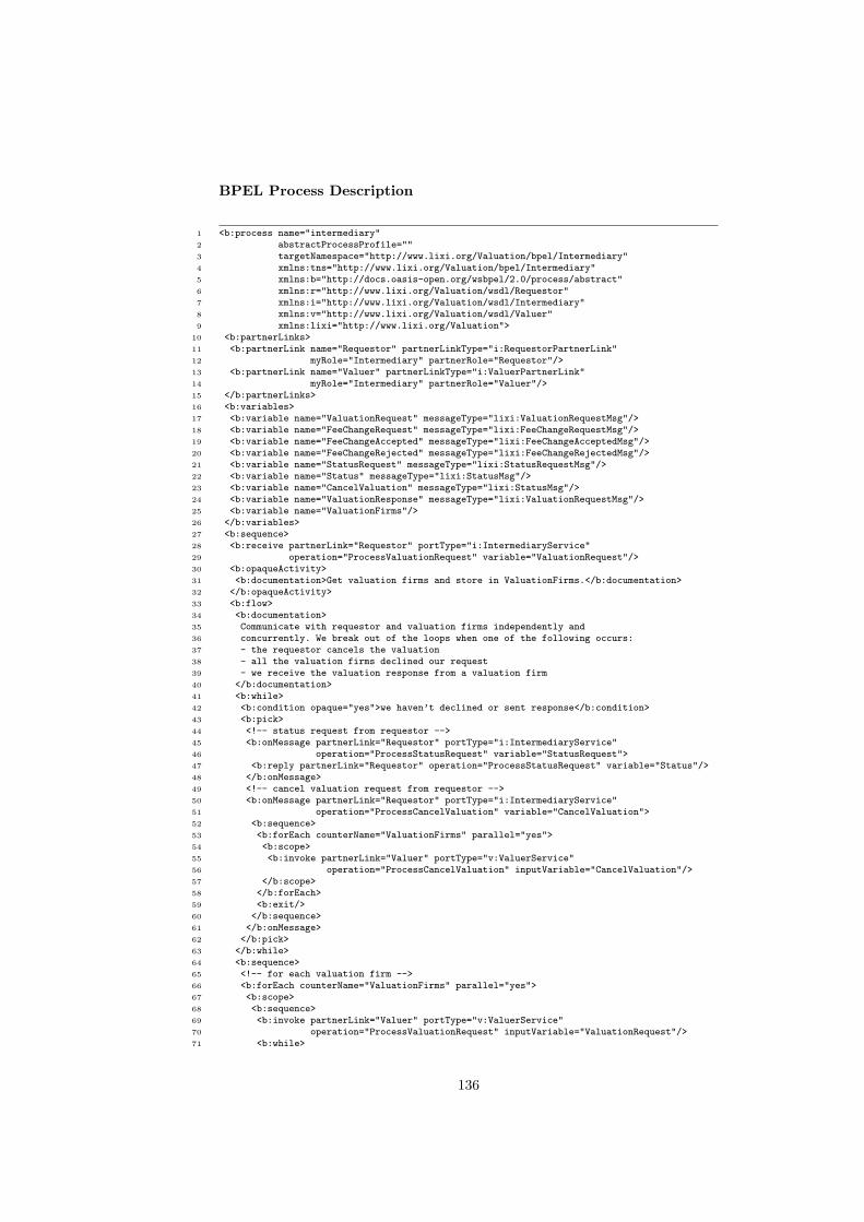
BPEL Process Description
1 <b:process name="intermediary"2 abstractProcessProfile=""3 targetNamespace="http://www.lixi.org/Valuation/bpel/Intermediary"4 xmlns:tns="http://www.lixi.org/Valuation/bpel/Intermediary"5 xmlns:b="http://docs.oasis-open.org/wsbpel/2.0/process/abstract"6 xmlns:r="http://www.lixi.org/Valuation/wsdl/Requestor"7 xmlns:i="http://www.lixi.org/Valuation/wsdl/Intermediary"8 xmlns:v="http://www.lixi.org/Valuation/wsdl/Valuer"9 xmlns:lixi="http://www.lixi.org/Valuation">
10 <b:partnerLinks>11 <b:partnerLink name="Requestor" partnerLinkType="i:RequestorPartnerLink"12 myRole="Intermediary" partnerRole="Requestor"/>13 <b:partnerLink name="Valuer" partnerLinkType="i:ValuerPartnerLink"14 myRole="Intermediary" partnerRole="Valuer"/>15 </b:partnerLinks>16 <b:variables>17 <b:variable name="ValuationRequest" messageType="lixi:ValuationRequestMsg"/>18 <b:variable name="FeeChangeRequest" messageType="lixi:FeeChangeRequestMsg"/>19 <b:variable name="FeeChangeAccepted" messageType="lixi:FeeChangeAcceptedMsg"/>20 <b:variable name="FeeChangeRejected" messageType="lixi:FeeChangeRejectedMsg"/>21 <b:variable name="StatusRequest" messageType="lixi:StatusRequestMsg"/>22 <b:variable name="Status" messageType="lixi:StatusMsg"/>23 <b:variable name="CancelValuation" messageType="lixi:StatusMsg"/>24 <b:variable name="ValuationResponse" messageType="lixi:ValuationRequestMsg"/>25 <b:variable name="ValuationFirms"/>26 </b:variables>27 <b:sequence>28 <b:receive partnerLink="Requestor" portType="i:IntermediaryService"29 operation="ProcessValuationRequest" variable="ValuationRequest"/>30 <b:opaqueActivity>31 <b:documentation>Get valuation firms and store in ValuationFirms.</b:documentation>32 </b:opaqueActivity>33 <b:flow>34 <b:documentation>35 Communicate with requestor and valuation firms independently and36 concurrently. We break out of the loops when one of the following occurs:37 - the requestor cancels the valuation38 - all the valuation firms declined our request39 - we receive the valuation response from a valuation firm40 </b:documentation>41 <b:while>42 <b:condition opaque="yes">we haven’t declined or sent response</b:condition>43 <b:pick>44 <!-- status request from requestor -->45 <b:onMessage partnerLink="Requestor" portType="i:IntermediaryService"46 operation="ProcessStatusRequest" variable="StatusRequest">47 <b:reply partnerLink="Requestor" operation="ProcessStatusRequest" variable="Status"/>48 </b:onMessage>49 <!-- cancel valuation request from requestor -->50 <b:onMessage partnerLink="Requestor" portType="i:IntermediaryService"51 operation="ProcessCancelValuation" variable="CancelValuation">52 <b:sequence>53 <b:forEach counterName="ValuationFirms" parallel="yes">54 <b:scope>55 <b:invoke partnerLink="Valuer" portType="v:ValuerService"56 operation="ProcessCancelValuation" inputVariable="CancelValuation"/>57 </b:scope>58 </b:forEach>59 <b:exit/>60 </b:sequence>61 </b:onMessage>62 </b:pick>63 </b:while>64 <b:sequence>65 <!-- for each valuation firm -->66 <b:forEach counterName="ValuationFirms" parallel="yes">67 <b:scope>68 <b:sequence>69 <b:invoke partnerLink="Valuer" portType="v:ValuerService"70 operation="ProcessValuationRequest" inputVariable="ValuationRequest"/>71 <b:while>
136

72 <b:condition opaque="yes">73 we haven’t received status declined or valuation response from valuation firm.74 </b:condition>75 <b:pick>76 <!-- status update from valuer -->77 <b:onMessage partnerLink="Valuer" portType="i:IntermediaryService"78 operation="ProcessStatus" variable="Status">79 <b:if>80 <b:condition opaque="yes">81 if status is ’accepted’ and we haven’t cancelled yet.82 </b:condition>83 <!-- cancel all other valuation firms-->84 <b:forEach counterName="ValuationFirms" parallel="yes">85 <b:scope>86 <b:if>87 <b:condition opaque="yes">88 if valuation firm is not the one that has just accepted.89 </b:condition>90 <b:invoke partnerLink="Valuer" portType="v:ValuerService"91 operation="ProcessCancelValuation" inputVariable="CancelValuation"/>92 </b:if>93 </b:scope>94 </b:forEach>95 <b:elseif>96 <b:condition opaque="yes">if status is ’declined’</b:condition>97 <b:sequence>98 <b:opaqueActivity>99 <b:documentation>keep track of valuers that declined</b:documentation>
100 </b:opaqueActivity>101 <b:if>102 <b:condition opaque="yes">if all valuers declined</b:condition>103 <b:sequence>104 <b:invoke partnerLink="Requestor" portType="r:RequestorService"105 operation="ProcessStatus" inputVariable="Status"/>106 <b:exit/>107 </b:sequence>108 </b:if>109 </b:sequence>110 </b:elseif>111 </b:if>112 </b:onMessage>113 <!-- fee change request from valuer -->114 <b:onMessage partnerLink="Valuer" portType="i:IntermediaryService"115 operation="ProcessFeeChangeRequest" variable="FeeChangeRequest">116 <b:if>117 <b:condition opaque="yes">some business condition</b:condition>118 <b:invoke partnerLink="Valuer" portType="i:IntermediaryService"119 operation="ProcessFeeChangeAccepted" inputVariable="FeeChangeAccepted"/>120 <b:else>121 <b:invoke partnerLink="Valuer" portType="v:ValuerService"122 operation="ProcessFeeChangeRejected" inputVariable="FeeChangeRejected"/>123 </b:else>124 </b:if>125 </b:onMessage>126 <!-- valuation response from valuer -->127 <b:onMessage partnerLink="Valuer" portType="i:IntermediaryService"128 operation="ProcessValuationResponse" variable="ValuationResponse">129 <b:sequence>130 <b:invoke partnerLink="Requestor" portType="r:RequestorService"131 operation="ProcessValuationResponse" inputVariable="ValuationResponse"/>132 <b:exit/>133 </b:sequence>134 </b:onMessage>135 </b:pick>136 </b:while>137 </b:sequence>138 </b:scope>139 </b:forEach>140 </b:sequence>141 </b:flow>142 </b:sequence>143 </b:process>
137