An Elasto/Plastic Model of the Ultrasonic Additive ... · AN ELASTO/PLASTIC MODEL OF THE ULTRASONIC...
24
AN ELASTO/PLASTIC MODEL OF THE ULTRASONIC ADDITIVE MANUFACTURING Q. Mao, N. Coutris, and G.M. Fadel Department of Mechanical Engineering, Clemson University, SC 29630 Abstract Ultrasonic additive manufacturing (UAM) is a solid-state fabrication process that utilizes ultrasonic energy to bond metal foils layer by layer. It has been shown that bond formation is closely related to the plastic deformation of the material at the bonding interface. As a result, a material model is necessary to characterize the elastic and plastic deformation of material under UAM conditions. The existing material models for UAM suffer from the following issues: 1) the models are established based on experimental data of a material different from the material used in UAM. 2) The models have not fully accounted for the influential factors in UAM. Therefore, a new material model is established by modifying the Johnson-Cook model which is known to be simple but effective to capture plasticity at elevated temperature and high strain rate. The model is based on experiments carried out on aluminum 6061-T6 which has been extensively used in the ultrasonic additive manufacturing. Ultrasound-induced effects including strain hardening, strain rate hardening, acoustic softening, and thermal softening are considered in the model. In addition to plasticity, the bond formation/plastic deformation is also profoundly affected by the dynamics of the built feature which has not been considered in combination with plasticity in the existing studies. As a result, a UAM model is established in which both the mechanical and dynamic effects are taken into account. The model is shown to characterize well the plastic deformation at the bonding interface both qualitatively and quantitatively by comparing its predictions with experimental observations. Introduction Although the UAM has only existed for a decade [1], its bonding process stems from the ultrasonic metal welding (UMW) which was invented over 50 years ago and is extensively implemented in industry. Numerous experimental investigations have been conducted to understand the bond mechanism of UMW [2-6]. However, the mechanics behind the bonding process are still far from being completely understood. Particularly, the plastic shear deformation of materials at the bonding interface, which has been highlighted as a critical factor for bond formation [5], lacks full investigation and characterization. In addition, the dynamics of the built feature also have an influence on bond formation: the built feature undergoes resonance at a critical aspect ratio and reduces the differential motion between the top foil and the built feature. The loss of differential motion leads to loss of sufficient friction and thus results in bonding failure. Thus, the goals of this paper include: 1) characterizing the material behavior under UAM conditions and establishing a generic material model that is capable to predict the bonding mechanics. 2) Studying the influence of the change of macroscopic dynamics of the system on the bonding mechanics. 3) Relating bond mechanics to bond quality. 317 Solid Freeform Fabrication Symposium – An Additive Manufacturing Conference Reviewed Paper Solid Freeform Fabrication 2016: Proceedings of the 27th Annual International
Transcript of An Elasto/Plastic Model of the Ultrasonic Additive ... · AN ELASTO/PLASTIC MODEL OF THE ULTRASONIC...

AN ELASTO/PLASTIC MODEL OF THE ULTRASONIC ADDITIVE
MANUFACTURING
Q. Mao, N. Coutris, and G.M. Fadel
Department of Mechanical Engineering, Clemson University, SC 29630
Abstract
Ultrasonic additive manufacturing (UAM) is a solid-state fabrication process that utilizes
ultrasonic energy to bond metal foils layer by layer. It has been shown that bond formation is
closely related to the plastic deformation of the material at the bonding interface. As a result, a
material model is necessary to characterize the elastic and plastic deformation of material under
UAM conditions. The existing material models for UAM suffer from the following issues: 1) the
models are established based on experimental data of a material different from the material used
in UAM. 2) The models have not fully accounted for the influential factors in UAM. Therefore, a
new material model is established by modifying the Johnson-Cook model which is known to be
simple but effective to capture plasticity at elevated temperature and high strain rate. The model is
based on experiments carried out on aluminum 6061-T6 which has been extensively used in the
ultrasonic additive manufacturing. Ultrasound-induced effects including strain hardening, strain
rate hardening, acoustic softening, and thermal softening are considered in the model. In addition
to plasticity, the bond formation/plastic deformation is also profoundly affected by the dynamics
of the built feature which has not been considered in combination with plasticity in the existing
studies. As a result, a UAM model is established in which both the mechanical and dynamic effects
are taken into account. The model is shown to characterize well the plastic deformation at the
bonding interface both qualitatively and quantitatively by comparing its predictions with
experimental observations.
Introduction
Although the UAM has only existed for a decade [1], its bonding process stems from the
ultrasonic metal welding (UMW) which was invented over 50 years ago and is extensively
implemented in industry. Numerous experimental investigations have been conducted to
understand the bond mechanism of UMW [2-6]. However, the mechanics behind the bonding
process are still far from being completely understood. Particularly, the plastic shear deformation
of materials at the bonding interface, which has been highlighted as a critical factor for bond
formation [5], lacks full investigation and characterization. In addition, the dynamics of the built
feature also have an influence on bond formation: the built feature undergoes resonance at a critical
aspect ratio and reduces the differential motion between the top foil and the built feature. The loss
of differential motion leads to loss of sufficient friction and thus results in bonding failure. Thus,
the goals of this paper include: 1) characterizing the material behavior under UAM conditions and
establishing a generic material model that is capable to predict the bonding mechanics. 2) Studying
the influence of the change of macroscopic dynamics of the system on the bonding mechanics. 3)
Relating bond mechanics to bond quality.
317
Solid Freeform Fabrication 2016: Proceedings of the 27th Annual International Solid Freeform Fabrication Symposium – An Additive Manufacturing Conference
Reviewed Paper
Solid Freeform Fabrication 2016: Proceedings of the 27th Annual International

Motivation
The understanding of fundamental mechanisms of UAM bonding is limited. While it has been
agreed by researchers that in general the bond formation undergoes three stages: 1) plastic
deformation of asperities and break-up of surface oxides, 2) increasing contact area of pure metals
with plastic flow enclosing the voids, and 3) bond formation and the maintaining of bonds through
plastic deformation, yet the mechanisms behind bond formation is still arguable and even
contradictory [2-5]. Early studies by Joshi showed that bonds are formed as the material undergoes
diffusion, localized melting, and mechanical interlocking [7]. In support of Joshi, Gunduz et al.
observed significant plastic flow at a strain rate of up to 103 /𝑠. The plastic flow on one hand
initiates diffusion by increasing vacancy concentration, on the other induces localized melting
through adiabatic heating [6]. Lee et al. observed mechanical interlocking between soft and hard
material while bonding Cu to Ni-plated Cu [4]. Severe plastic deformation in copper is observed.
According to Janaki Ram, however, the bonding process is universally due to solid-state metallic
adhesion which involves adhesion of layers of atoms that create an apparent interfacial bond
strength across the interface [3][8]. They further pointed out that the plastic deformation played a
major role in all the three stages of bond formation as they repeat themselves in welding process.
Recrystallization is reported by several researchers [4] [9] [10]. Recrystallization is observed to be
localized at the bond interface and is caused by heat generated from plastic deformation and
interfacial friction. While the actual mechanism of UMW is arguable and could be material
specific, it is evident that plastic deformation serves as a key component in bond formation.
Without sufficient plastic deformation the bond would be degraded or even fail. If the plastic
deformation at the bond interface can be quantified, it is possible to use it as an indicator for
predicting bond quality and thus connecting UAM operating parameters (vibration amplitude,
compression load, and weld speed) to bond quality through computation. In order to quantify the
plastic deformation, the bonding mechanics of UAM should be understood and a model be
established.
Pioneering work is done by de Vries who studied the mechanics of UMW, which shares a
similar bonding principle with UAM but generates bonds only at contact points rather than along
contact lines. They studied the internal stress within the top and bottom foil as well as frictional
stress at the bond interface, and established a bond criterion that requires the internal stress to be
greater than the yield strength of the material to initiate bonding. The internal stress is calculated
based on both the yield stress which depends solely on temperature, and the compressional stress.
Behind this mechanics model, several assumptions are made: 1) the plasticity is assumed to be
perfect (free of hardening) and yield stress decreases as local temperature increases. 2) The friction
coefficient at the bonding interface is assumed as a constant. 3) The ultrasonic sonotrode has a flat
surface and thus the stress state is 2-D. While the mechanics model and the associated bond
criterion provides insights to the understanding of UMW bonding, it is far from enough to
characterize the mechanics in UAM. First, the yield stress under UAM condition is affected by
multiple factors: plastic strain, high plastic strain rate, ultrasonic energy, and thermal energy.
Second, the two mating foils undergo stick-slip friction which is affected by the dynamics of the
built feature [11]. The friction coefficient is not constant but rather temperature-dependent [12].
Third, the stress state in UAM is not 2-D plane stress since the sonotrode is of cylindrical shape
rather than flat. Therefore the 3-D stress state has to be considered in the mechanics model.
318

Another factor that prevents the UMW model from being implemented for UAM is the difference
in the dimensions of foils. While the dimension of the foils for UMW is flexible, the foils used for
UAM process have fixed dimensions: 0.94 in. (23.88 mm) in width, 0.0059 in. (0.15 mm) in
thickness, and customized length within the work space of UAM. Due to the small foil thickness,
the dynamics of the top foil is generally insignificant when compared with that of the built feature
and therefore the force required to excite the top foil is neglected.
UAM models were also established to understand the UAM bonding mechanics [13-15]. In
these models, the plasticity of the material models are of critical importance. Siddiq and
Ghassemieh modified the cyclic plasticity model proposed by Lemaitre and Chaboche to account
for the acoustic and thermal softening effects [13] [16]. The cyclic plasticity model, however, is
based on cyclic loading tests that are carried out at a strain rate (10−3/s) much lower than that of
UAM (103~104/s), and on a material different from what has been used for UAM. As a result,
the hardening effects due to strain rate are not taken into account. Additionally, the experimental
data used for characterization of acoustic softening effect is from aluminum single crystal which
is much softer than the aluminum alloy used in UAM. Kelly et al. utilized a power law function to
characterize the stress-strain relationship in the plastic region for a UAM model bonding aluminum
alloy 1100 [14]. In the stress-strain relationship, the thermal softening effect is characterized by
the exponential term and the acoustic softening by adding a factor to the power law function. Due
to the lack of experimental investigation, the power law plasticity model is built on data of
aluminum single crystal. The effect of strain rate is not considered. Siddiq and El Sayed modified
a crystal plasticity model to account for acoustic and thermal softening in UAM [15]. The model
parameters are optimized to fit the stress strain curves of aluminum single crystal. The model is
then extended to polycrystalline aluminum based on EBSD studies of aluminum 6061-O. In this
way, they try to understand the mechanism of acoustic and thermal softening in UAM at a
microscopic scale. Although the crystal plasticity model reflects the change in microstructure of
the material, the number of model parameters significantly exceeds the number of observable
parameters due to the complexity of the model and the lack of experimental investigation, and an
optimization tool has to be introduced, which undermines the reliability of the model. In summary,
the existing UAM plasticity models suffer from the following issues: 1) models are built on
experimental data from a different test condition or a different material, 2) models are too simple
to fully characterize or too complicated to realistically reflect the material behavior. As a result,
an appropriate material model should be established such that it can fully capture the material
behavior by accounting for all the influential factors and its model parameters are sufficiently
calibrated by experimental data of the correct material.
While the plasticity governs the plastic stress in response to strain, the dynamics of the built
feature also have a fundamental influence on the plastic stress through friction. As additional layers
are deposited, the differential motion between the sonotrode and the built feature changes, which
affects the interfacial frictional forces and thus the plastic shear deformation at the interface.
Robinson et al. first documented the increasing deflection as the height of the built feature
approaches its width (i.e. height-to-width ratio equals 1) and attributed the phenomenon to a lack
of stiffness of the built feature with respect to the vibrating sonotrode [18]. Alternatively, Zhang
and Li associated the increase of deflection to a dynamic effect of the superposition of traveling
waves imposed by the vibrating sonotrode [12]. Gibert et al. found that beyond the critical height-
to-width ratio, bonding can be reinitiated and therefore the loss of stiffness is a dynamic effect
319
[11]. Furthermore, by studying the dynamics of the built feature they show that the built feature is
close to resonance at the as height-to-width ratio approaches 1 under excitation of the ultrasonic
sonotrode. As a result, the vibration of the built feature is synchronized with that of the sonotrode
resulting in lack of differential motion for initiating frictional force and plastic shear force. This
change of dynamics has not been accounted in the studies of bonding mechanics and therefore its
effect on bond formation is not clear.
The Material Model
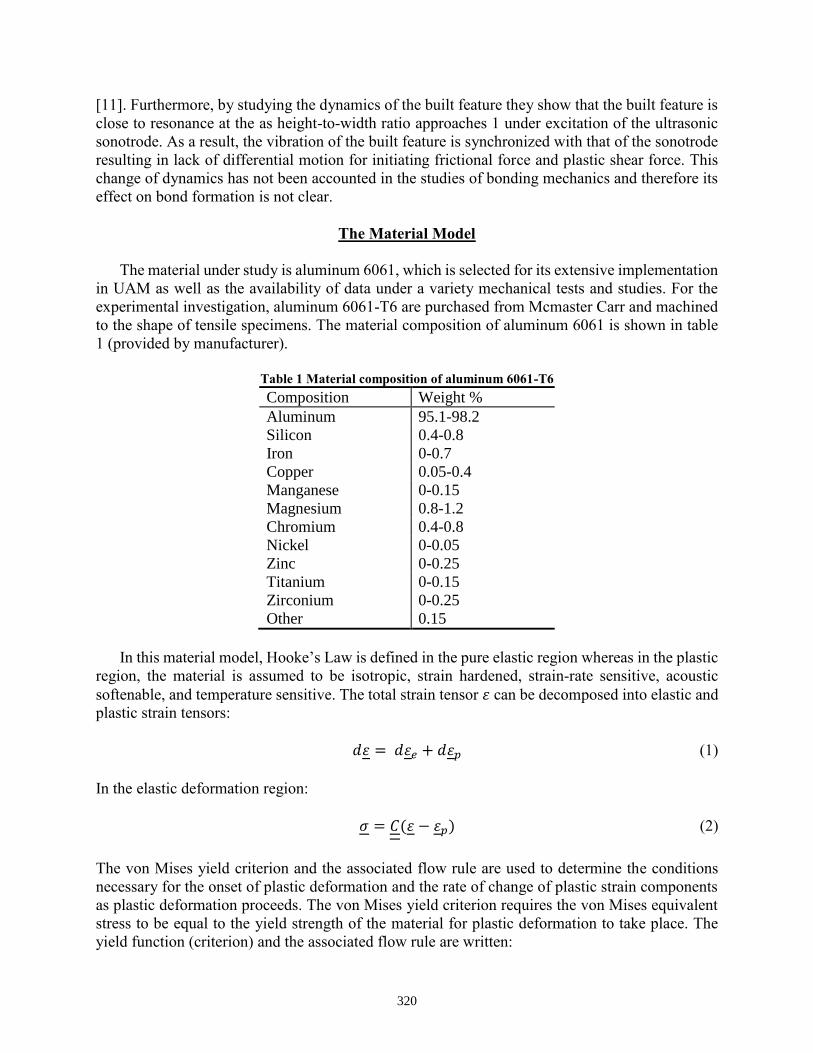
The material under study is aluminum 6061, which is selected for its extensive implementation
in UAM as well as the availability of data under a variety mechanical tests and studies. For the
experimental investigation, aluminum 6061-T6 are purchased from Mcmaster Carr and machined
to the shape of tensile specimens. The material composition of aluminum 6061 is shown in table
1 (provided by manufacturer).
Table 1 Material composition of aluminum 6061-T6
Composition Weight % Aluminum 95.1-98.2 Silicon 0.4-0.8 Iron 0-0.7 Copper 0.05-0.4 Manganese 0-0.15 Magnesium 0.8-1.2 Chromium 0.4-0.8 Nickel 0-0.05 Zinc 0-0.25 Titanium 0-0.15 Zirconium 0-0.25 Other 0.15
In this material model, Hooke’s Law is defined in the pure elastic region whereas in the plastic
region, the material is assumed to be isotropic, strain hardened, strain-rate sensitive, acoustic
softenable, and temperature sensitive. The total strain tensor 𝜀 can be decomposed into elastic and
plastic strain tensors:
𝑑𝜀 = 𝑑𝜀𝑒 + 𝑑𝜀𝑝 (1)
In the elastic deformation region:
𝜎 = 𝐶(𝜀 − 𝜀𝑝) (2)
The von Mises yield criterion and the associated flow rule are used to determine the conditions
necessary for the onset of plastic deformation and the rate of change of plastic strain components
as plastic deformation proceeds. The von Mises yield criterion requires the von Mises equivalent
stress to be equal to the yield strength of the material for plastic deformation to take place. The
yield function (criterion) and the associated flow rule are written:
320

f(σ̅) = |σ̅ − α| − (𝜎0 + 𝑅) = 0 (3)
dεp = dλ∂f
∂σ̅ (4)
Where σ̅ is the von Mises equivalent stress, α is the back stress in kinematic hardening. Since
kinematic hardening is not considered: α = 0. 𝜎0 is the initial yield stress, 𝑅 is the isotropic
hardening term. εp is the plastic strain of the material, 𝑑λ is a plastic multiplier.
In this study, the Johnson-Cook (JC) model [19] is selected and modified to characterize the
material plasticity for its simple mathematical form and extensive application. Although the model
is completely empirical, it is effective in characterizing deformation of large plastic strain, in high
plastic strain rate, and at elevated temperature. Additionally, the JC model is a particular type of
von Mises plasticity model with an explicit form of hardening law and rate dependence. The
original JC model is written [19]:
𝜎 = (𝐴 + 𝐵𝜀̅𝑛)(1 + 𝐶𝑙𝑛�̇̅�
�̇̅�0)(1 − 𝑇∗𝑚) (5)
Where 𝜀̅𝑛 is the equivalent plastic strain, 𝜀̅̇ is the equivalent plastic strain rate, 𝜀̅0̇ is a reference
equivalent plastic strain rate defined as: 𝜀̅0̇ = 1 /𝑠. 𝐴 is the yield strength measured at zero-plastic-
strain, unit-plastic-strain-rate, and room-temperature. 𝐵 is the strain-hardening constant, 𝑛 the
strain-hardening exponent, 𝐶 the strain-rate constant, 𝑚 the thermal-softening exponent, and 𝑇∗ a
room-temperature (𝑇𝑟𝑜𝑜𝑚)-based dimensionless temperature defined as: 𝑇∗ =𝑇−𝑇𝑟𝑜𝑜𝑚
𝑇𝑚𝑒𝑙𝑡−𝑇𝑟𝑜𝑜𝑚, where
𝑇𝑚𝑒𝑙𝑡 is the melting temperature. The first term defines the strain hardening, the second term
defines the strain rate hardening, and the third term defines the softening at elevated temperature.
At room temperature (𝑇∗ = 0) and at the reference strain rate 𝜀̅̇ = 𝜀̅0̇, the JC model is reduced to:
𝜎 = 𝐴 + 𝐵𝜀̅𝑛 (6)
A set of parameters for aluminum 6061-T6 can be obtained based on the quasi-static tensile test of
aluminum 6061-T6: 𝐴 = 311.22 𝑀𝑃𝑎, 𝐵 = 240.11 𝑀𝑃𝑎, 𝑛 = 0.37.
The JC model, despite its mathematical simplicity and modeling advantages, has a limitation
to characterize plasticity with accuracy under the conditions in which high strain rate and
ultrasound-induced softening are involved. It has been shown by multiple investigations that
metals with face-centered-cubic (f.c.c.) structure demonstrate a dramatic increase of dependence
of dynamic flow stress on the instantaneous strain rate as the strain rate exceeds certain threshold
(typically around 103 /𝑠) (fig. 1) [20][21]. It is believed that this abrupt change of strain rate
sensitivity of the flow stress is due to the change of deformation mechanism. At low strain rate,
the deformation is governed by the cutting or by-passing of obstacles by the dislocations. As the
strain rate exceeds the threshold, the deformation starts to be controlled by phonon drag forces and
the flow stress necessary to deform the material increases abruptly. This change of mechanism,
however, is beyond the modeling capability of the standard JC model [20]. As a result, the JC
model has to be modified such that both mechanisms are taken into account. Lesuer et al. proposed
321

a material model which utilizes different equations for characterizing the strain rate dependence
based on the different mechanisms [20]. At low strain rate, a relation in form of Arrhenius equation
is introduced based on the work of Frost and Ashby [23]:
𝜀1̇ = 𝜀0̇exp [𝑄
𝑘𝑇(1 −
𝜎
𝜏)] (7)
Where 𝜀1̇ represents the strain rate at which cutting and bypassing of obstacles by the dislocation
is dominant, 𝜀0̇ is a reference strain rate, 𝑄 is the activation energy, 𝑘 is Boltzmann’s constant, 𝜎
is the flow stress, 𝜏 is the strength of obstacles at 0 K, and 𝑇 is temperature in Kelvin. At high
strain rate, the relation is a power law equation:
𝜀2̇ = 𝐶1𝜎𝐶2 (8)
Where 𝜀2̇ represents the strain rate at which the phonon drag force on dislocation is dominant, 𝐶1
and 𝐶2 are constants whose values are obtained through curve fitting. The relations at low and high
strain rates are combined to obtain the effective strain rate:
𝜀�̇�𝑓𝑓 =𝜀1̇𝜀2̇
𝜀1̇ + 𝜀2̇ (9)
Similar material models can also be found in work by Sakino [21] and Manes et al.[24].
The typical UAM processes involve strain rate at 103~104/s. The range of the shear strain rate
can be calculated with the assumptions: 1) there exists no slip between the sonotrode and the top
foil, i.e. the top surface of the top foil vibrates at the same amplitude as the sonotrode, 2) the bottom
surface is fully welded to the built feature and is therefore fixed (fig. 2). The vibration amplitude
𝐴 varies between 5 to 50 µm while the thickness of the top foil 𝑡 is roughly 150 µm. As a result,
the shear strain and strain rate of the top foil can be estimated:
𝜏 =𝐴
𝑡 (10)
�̇� =𝜏
𝑇/4 (11)
The calculated shear strain rate ranges from 2.66 × 10³to 2.66 × 10⁴ 𝑠−1. This range, however,
falls around the turning point which indicates the transition of mechanisms in the rate sensitivity
diagram. Since in real material, the transition of mechanism will not take place in all forest
dislocations simultaneously, the sharp turn predicted by the proposed material model does not
align with the experimental data.
322

Fig.1 The strain rate sensitivity diagram of aluminum 6061-T6. Experimental data are taken from [20] and
[22].
Fig.2 Schematics of the interaction between sonotrode and top foil.
In order to better characterize the flow stress at transition phase of the mechanisms, more
experimental data are studied to find a model that works better specifically for the UAM. Fig. 3
shows the flow stress-strain rate diagram presented by Yadav et al. [25]. They collected
experimental data of aluminum 6061-T6 from multiple studies and specifically examined the
change of flow stress at the transition phase (fig. 3). Based on the data provided, a material model
similar to that of Yadav et al. is implemented [25]:
�̅�
𝜎0̅̅̅̅= 𝐶 + 𝐷(
�̇̅�
𝜀0̅̅ ̅̇)𝑏 (12)
Where 𝜎0 is the stress at the reference strain rate 𝜀0̇̅ = 1 /𝑠. 𝐶, 𝐷, and 𝑚 are constants whose
values are determeind by curve fitting: 𝐶 = 0.46, 𝐷 = 0.49, 𝑏 = 0.10. The comparison between
the prediction of the model and the experimental data is shown in fig. 4. Based on the observation
of little variation in shapes of the stress-strain curves at different strain rates, assumption has been
made that the shapes of hardening curves at different strain rates are identical.
A = 5 ~ 50
µm
t = ~150 µm
Sonotrode
Top foil
Built feature
P = 400N ~ 2kN
µm
323
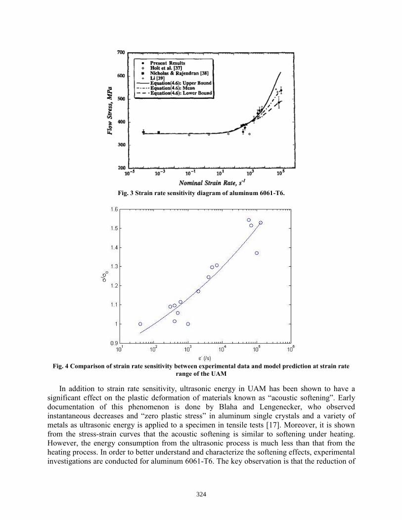
Fig. 3 Strain rate sensitivity diagram of aluminum 6061-T6.
Fig. 4 Comparison of strain rate sensitivity between experimental data and model prediction at strain rate
range of the UAM
In addition to strain rate sensitivity, ultrasonic energy in UAM has been shown to have a
significant effect on the plastic deformation of materials known as “acoustic softening”. Early
documentation of this phenomenon is done by Blaha and Lengenecker, who observed
instantaneous decreases and “zero plastic stress” in aluminum single crystals and a variety of
metals as ultrasonic energy is applied to a specimen in tensile tests [17]. Moreover, it is shown
from the stress-strain curves that the acoustic softening is similar to softening under heating.
However, the energy consumption from the ultrasonic process is much less than that from the
heating process. In order to better understand and characterize the softening effects, experimental
investigations are conducted for aluminum 6061-T6. The key observation is that the reduction of
324
the plastic stress is linearly proportional to the input of the ultrasound intensity (fig. 5). No
macroscopic temperature increase is observed [26]. As a result, the JC model is modified such that
the stress reduction due to ultrasound can be characterized as a linear function of the ultrasound
intensity [26].
�̅�
𝜎0̅̅̅̅= 1 − 𝑑𝐼𝑢 (13)
Where 𝜎 is the flow stress under ultrasonic irradiation, and 𝜎0̅̅ ̅ is the reference flow stress without
ultrasonic irradiation. Both 𝜎 and 𝜎0̅̅ ̅ are taken as averages of the stresses measured at true plastic
strain 𝜀𝑝 = 0.2 and 𝜀𝑝 = 0.3 in order to obtain an accurate measuring of stress reduction. 𝐼𝑢 is
the ultrasound intensity, and 𝑑 is a constant that fits the model to experimental data. At room
temperature and reference strain rate, the value of 𝑑 is determined as 𝑑 = 1.2 × 10⁻⁴/J. Notice
that in the experimental study of acoustic softening, the total ultrasonic energy 𝐸𝑢 can be directly
measured by the ultrasonic welder power supply [26]. In the UAM process, while the sonotrode
amplitude is known, a direct measure of ultrasonic energy is not applicable. In order to estimate
the applied energy, a relation is introduced to associate the ultrasound intensity to the oscillation
magnitude of the ultrasonic field. The relation is written as [27]:
𝐼𝑢 = 𝜌�̅�2𝜔2𝑐 (14)
Where �̅� is the equivalent oscillation amplitude of the ultrasound field. 𝜌 is the density of the
medium, 𝑐 is the speed of sound in the medium, and 𝜔 is the angular frequency of the ultrasound,
defined as 𝜔 = 2𝜋𝑓. 𝑓 is the frequency of ultrasound and is fixed at 20 kHz. Since the bonding
interface is very close to the sonotrode surface (roughly 0.1 mm), it is assumed that the oscillation
amplitude of the ultrasonic field is the same as the amplitude of the sonotrode. Consequently, the
ultrasound intensity can be characterized using vibration amplitude. By introducing equation (13)
and (14), the acoustic softening can be incorporated into the stress-strain relation and thus the
plasticity model (fig. 6). This characterization relies on the assumption that the amplitude of the
ultrasound at the bonding interface equals the vibration amplitude of the sonotrode. In reality,
however, intermittent slip takes place between the top foil and sonotrode, as well as between the
top foil and the built feature which leads to an overestimation of the energy input at the bonding
interface. On the other hand, the acoustic softening effect of the ultrasonic energy is
underestimated in the experimental investigation due to the fact that a portion of the delivered
ultrasonic energy is dissipated in the supporting structures rather than the in the specimen.
325

Fig. 5 The stress reduction is linearly proportional to ultrasonic energy input [26]
Fig. 6 The softening of aluminum 6061-T6 predicted by the model.
The temperature effects on aluminum 6061-T6 is modeled using the original JC model based
on the work of Banerjee and Bhawalkar [28] who studied plasticity of the aluminum 6061-T6 at
the elevated temperature and strain rate. In the UAM process, the ambient temperature is typically
controlled to 300˚F (around 150 ̊ C). However, the local temperature at the bonding interface could
be significantly higher due to interfacial friction and severe plastic deformation. Based on the
experimental data provided, the exponential constant within the model is determined: 𝑐 = 0.68,
and the melting temperature is set to 𝑇𝑚 = 1000 𝐾.
326

Fig.7 The comparison of experimental data and model prediction of the stress reduction due to temperature
in aluminum 6061-T6.
As a result, the modified JC model is obtained by incorporating the effects of high strain rate,
acoustic softening, and temperature (equation (14)). The constants are given in table 2.
Furthermore, the modified JC model and the classical JC model are evaluated in terms of their
performances in characterizing different material behaviors under conditions of UAM process
(Table 3). In the next section, the modified JC model will be implemented to a finite element UAM
model for understanding the material deformation in UAM bonding process.
𝜎 = (1 − 𝑑𝐼𝑢)(𝐴 + 𝐵𝜀̅𝑎){𝐶 + 𝐷(�̇̅�
�̇̅�0)𝑏}(1 − 𝑇∗𝑐) (15)
Table 2 Constants for the modified JC model
𝑨/MPa 𝑩/MPa 𝑪 𝑫 𝒂 𝒃 𝒄 𝒅/ J
311.22 240.11 0.46 0.49 0.28 0.10 0.68 1.2e-4
Table 3 Comparison of classical and modified JC models
Classical JC model Modified JC model Strain hardening Characterized based on quasi-
static test Characterized based on quasi-
static test Strain rate hardening Inaccurate prediction beyond
strain rate of 𝟏𝟎𝟑 /𝒔 Accurate prediction up to strain
rate 𝟏𝟎𝟓 /𝒔 Thermal softening Characterized based on tests at
elevated temperatures Characterized based on tests at
elevated temperature Acoustic softening Not available Characterized based on acoustic
softening studies
327

Implementation of Material Model
The modified JC model is implemented in the finite element commercial software ABAQUS
6.14 using the user-defined material subroutine. The material model is integrated for computing
the global stiffness matrix. Given the load increment, the stiffness matrix is then used for finding
the displacement and strain increments that enable the system to reach quasi-static equilibrium. If
equilibrium cannot be reached, the load increment will be reduced and the procedure is repeated.
The steps are shown as follows. In the global level, the dynamics of the system is written as [28]:
𝑴�̈� + 𝑪�̇� + 𝑲𝑢 = 𝒇 (16)
𝑴 is the global mass matrix, 𝑪 is the global damping matrix, 𝑲 is the global stiffness matrix, and 𝒇
is external force vector. The dynamic equation is solved explicitly by decomposing each time step
into a large number of small time increments. At each time increment, the quasi-static equilibrium
is reached at each material point. The equation is written as:
𝑲𝒖 = 𝒇 (17)
𝑲 can be further decomposed:
𝑲 = ∫ 𝑩𝑻 𝑫𝒆𝒑𝑩𝒅𝜴 (18)
𝑩 is the deformation matrix, 𝑫𝒆𝒑 is the elastic-plastic constitutive matrix that is defined by the
material model. Write equation (17) into incremental form:
𝑲𝜟𝒖 = 𝜟𝒇 (19)
Since
𝜟𝑢 = 𝑩−𝟏𝜟𝜺 (20)
Where 𝜟𝜺 is the incremental strain. Inserting equations (18) and (20) into equation (19) yields:
𝑩𝑇𝑫𝒆𝒑𝜟𝜺 = 𝛥𝒇 (21)
Since 𝑫𝒆𝒑 depends implicitly on 𝜟𝜺, 𝜟𝜺 is found by integrating the constitutive law defined by
the material model. Two integration schemes are available: explicit or implicit. In this work, both
integration schemes have been explored and the explicit integration is implemented. The selection
process is explained in the following section. When 𝑫𝒆𝒑 is determined, the stress increment can
be obtained accordingly using the following equation.
328

𝜟𝝈 = 𝑫𝒆𝒑𝜟𝜺 (22)
Inserting equation (22) to (21) yields the incremental relation between 𝜟𝝈 and 𝜟𝒇 which leads to
a differential relation. This relation can be integrated over the material domain and yields:
∫ 𝑩𝑻𝝈 𝒅𝜴 = ∫ 𝒇 𝒅𝜴 (23)
Let 𝒒 = ∫ 𝑩𝑇𝝈 𝑑Ω, then a force residual 𝒓 is defined:
𝒓 = 𝒒 − 𝒇 (24)
The force residual is used a convergence criterion for numerical integration and is checked at each
iteration to see if equilibrium is achieved.
To sum up, the general algorithm is as follow:
1. Apply a load increment 𝛥𝒇, calculate for displacement increment 𝜟𝑢 and strain increment 𝜟𝜺.
2. Compute the stress increment 𝜟𝝈
3. Compute the residual 𝒓
4. If the residual 𝒓 exceeds a set tolerance, set 𝛥𝒇 = −𝒓 and return to step 1.
In step 1, 𝜟𝜺 can be obtained either through explicit or implicit scheme. The two integration
schemes are explained briefly. For the explicit integration scheme, the strain difference is
decomposed into elastic and plastic contributions:
𝑑𝜺 = 𝑑𝜺𝒆 + 𝑑𝜺𝒑 (25)
The relation between elastic stress and strain can thus be written:
𝑑𝝈 = 𝑫(𝑑𝜺 − 𝑑𝜺𝒑) (26)
Where 𝑫 is the elastic stiffness matrix. First introduce the von Mises yield function for isotropic
hardening:
𝑓(𝝈, 𝜺𝒑) = 𝑓(𝝈) − 𝑟(𝜺𝒑) − 𝜎𝑦 = 𝟎 (27)
Where 𝑟 is the isotropic hardening term, and 𝜎𝑦 is the initial yield stress. Then introduce the
consistency condition:
d𝑓(𝝈, 𝜺𝒑) =𝜕𝑓(𝝈)
𝜕𝝈𝑑𝝈 −
𝜕𝑟
𝜕𝜺𝒑𝑑𝜺𝒑 = 𝟎 (28)
329

And third the associated flow rule:
𝑑𝜺𝒑 = 𝑑𝜆𝜕𝑓(𝝈)
𝜕𝝈 (29)
Where 𝑑𝜆 is a multiplier that represents the magnitude of the plastic strain difference and 𝜕𝑓(𝝈)
𝜕𝝈
represents the flow direction of the plastic strain difference. By performing some algebraic
operations on equation (27)-(29), the magnitude of the plastic strain difference 𝑑𝜀𝑝 can be derived
in explicit form:
𝑑𝜆 =𝒏𝑫
𝒏 ∙ 𝑫𝒏 + 𝐻𝑑𝜺𝒆 (30)
Where 𝒏 =𝜕𝑓(𝝈)
𝜕𝝈 is the normal direction of the plastic flow. 𝐻 =
𝑑𝒓
𝑑𝜺𝒑 , 𝑟 is the isotropic hardening
term. 𝑫 is the elastic stiffness matrix. 𝑓 is the yield function. 𝑑𝜆 is the magnitude of 𝑑𝜀𝑝. Apply
forward Euler explicit integration scheme, equation (30) can be written in von Mises plasticity as:
𝑑𝜆 =𝜎 − 𝜎𝑦
3𝐺 + 𝐻𝑑𝜀𝑒 (31)
Where 𝜎 is the von Mises stress defined as 𝜎 = √3
2𝝈: 𝝈 and 𝜎𝑦 is the yield stress. The explicit
scheme is relatively simple to implement and does not require the update of Jacobian matrix.
However, it is conditionally stable and requires the time increment to be smaller than a critical
threshold defined as:
∆𝑡𝑐𝑟 ≈𝐿𝑐
𝑐𝑑 (32)
Where 𝐿𝑐 is the characteristic length of the element and 𝑐𝑑 is the dilatational wave speed.
The implicit integration scheme decomposes 𝑑𝜺 into an elastic trial strain 𝑑𝜀𝑒𝑡𝑟 and a plastic
corrective strain 𝑑𝜀𝑝𝑐:
𝑑𝜺 = 𝑑𝜺𝒆𝒕𝒓 − 𝑑𝜺𝒑
𝒄 (33)
Write the Hooke’s law in tonsorial form and introduce the flow rule (equation (28)) and equation
(33), with some algebra:
330

𝜎 + 3𝐺Δ𝜆 = 𝜎𝑡𝑟 (34)
Where 𝜎 is the von Mises stress and 𝜎𝑡𝑟 is defined as 𝜎𝑡𝑟 = √3
2𝝈𝒕𝒓: 𝝈𝒕𝒓. Insert equation (34) into
the yield function (equation (27)):
𝜎𝑡𝑟 − 3𝐺Δ𝜆 − 𝑟 − 𝜎𝑦 = 0 (35)
Since 𝑟 is a function of Δ𝜆, the equation is solved implicitly using Newton’s method. The
infinitesimal difference of the corrective plastic strain increment is derived:
dΔ𝜆 =3𝐺(𝜀̅𝑡𝑟 − Δ𝜆) − 𝑟 − 𝜎𝑦
3𝐺 + 𝐻 (36)
Where 𝜀̅𝑡𝑟is the von Mises strain defined as 𝜀̅𝑡𝑟 = √2
3𝜺𝒕𝒓: 𝜺𝒕𝒓. With dΔ𝜆 the being computed,
the stress and strain increments can be updated. The Jacobian matrix is then updated
accordingly using the following equation:
𝐉 =𝜕∆𝝈
𝜕∆𝜺 (37)
The implicit scheme is unconditionally stable since the yield criterion is imposed at each iteration.
Therefore the time increment is not necessarily small and the increment length can be adjusted as
iteration proceeds for optimum computational efficiency. However, the implicit iteration for
computing Δ𝜆 and the update of Jacobian matrix 𝐉 are computationally costly.
By implementing both the implicit and explicit integration scheme for solving the material
model, it is found that the explicit scheme requires much less time than the implicit scheme for
computing the stress-strain relation of a quasi-static tensile test. Moreover, the implicit scheme
suffers from convergence difficulties as material and geometric nonlinearity increases. The
implicit scheme is more sensitive to mesh resolution, loading speed, and nonlinearity of the
material model than the explicit scheme. As a result, the explicit scheme is selected for integrating
the modified JC material model. A user-defined material subroutine (VUMAT) is developed for
implementation of the model in ABAQUS. The work flowchart of the VUMAT is shown in fig.8.
331

Yes
Fig.8 flowchart of VUMAT
Validation of Material Model
The modified JC model is first implemented in simple finite element models for validation.
Specifically, three validations have been carried out: 1) 1-D tensile test subjected to ultrasonic
vibrations with different amplitudes 2) 1-D tensile tests at high strain rates and 3) 3-D quasi-static
tensile test. The predicted flow stress-plastic strain curves from the first two tests are compared
with those from the analytical models (fig. 8). In the tensile test under ultrasonic vibration (fig. 8
(a)), the simulated curves run parallel to the analytical curves with slight deviation possibly due to
error introduced by the explicit integration scheme. The maximum relative error for the prediction
is 2.9%. In the strain rate test (fig. 8 (b)), the simulated stress-strain curves demonstrates serrated
shapes at elevated strain rates possibly due to effects of dynamic loading as well as the elastic
predictor-plastic corrector algorithm implemented in VUMAT. Despite the serrated shape, the
simulated curves run parallel to the analytical curves and the relative errors are small. The errors
ABAQUS Calls VUMAT
Transfer state data from
the last iteration
Calculate the elastic
predictive stress
Call VUHARD, calculate
the yield stress with user-
defined constitutive
relation
Satisfy von Mises yield
criterion?
Calculate the plastic strain
increment using the explicit
equation:
Eqn (31)
Update stress with the elastic
predictive stress
No
Update the stress
Update the state variables
(strain, stain rate, yield
stress), the internal energy,
and inelastic energy
End of subroutine VUMAT, return to ABAQUS main
program
332

are larger at elevated strain rates and the maximum value is 6.4%. Fig. 9 (a) shows the comparison
between stress-strain curves from the 3-D quasi-static tensile simulation and from the experiment.
The 3-D model is built such that the dimensions are the same as the standard tensile test specimen
used in experimental studies (fig. 9 (b)). Only one quarter of the model is built for computational
efficiency. The prediction from the finite element aligns well with the experimental stress-strain
curve in both elastic and plastic deformation regions.
(a)
(b)
Fig. 8 (a) Stress-strain curves with different vibration amplitudes: 10, 20, and 30 µm. (b) Stress-strain curves
with different strain rates: 360/s, 3600/s, and 36000/s.
0.00E+00
1.00E+08
2.00E+08
3.00E+08
4.00E+08
5.00E+08
0 0.01 0.02 0.03 0.04
Flo
w s
tre
ss (
Pa)
Plastic strain 𝜺_𝒑Quasi-static, analytical Quasi-static, simulated
10 µm, analytical 10 µm, simulated
20 µm, analytical 20 µm, simulated
30 µm, analytical 30 µm, simulated
0.00E+00
1.00E+08
2.00E+08
3.00E+08
4.00E+08
5.00E+08
6.00E+08
0 0.01 0.02 0.03 0.04
Flo
w s
tre
ss (
Pa)
Plastic strain 𝜀_𝑝
Quasi-static, analytical Quasi-static, simulated
360/s, analytical 360/s, simulated
3600/s, analytical 3600/s, simulated
36000/s, analytical 36000/s, simulated
333

(a) (b)
Fig. 9 (a) The experimental and simulated stress strain curves generated from quasi-static tensile tests on
aluminum 6061-T6. (b) The 3-D finite element model of one quarter of the standard tensile specimen
The UAM Model
In order to understand how the changing dynamics of the system affect the bonding mechanics,
a 3-D UAM model is built using ABAQUS. The model introduces a sonotrode, a top foil, and a
built feature (fig. 10 (a)). Several simplifications are made in building the model. The sonotrode
is modeled using rigid shell elements whereas the top foil and built features are modeled as
deformable solid since the Titanium sonotrode is much harder than the foils. The laminar built
feature is simplified as a parallelepiped assuming that no interfacial sliding takes place between
two bonded layers. It should be noted that during welding severe plastic deformation is observed
only in a region close to the weld interface. The region is characterized by the refinement and
“flow” like morphology of the sub-grains and is typically 10 – 60 µm in depth from the weld
interface [29]. As a result, two plastic deformation layers are introduced and attached to the mating
surfaces of the top foil and the built feature respectively (fig.10 (b)). The elasticity and plasticity
of the material in the plastic deformation layers differ from those of the bulk material of the top
foil and the built feature. Specifically, acoustic softening only takes place in the layer and therefore
the yield stresses are much lower in the layer than in the bulk material. The effective elastic
modulus is also reduced by the surface asperities which have much lower stiffness than the bulk
material. When under compression loading, the surface asperities are much easier to undergo
plastic deformation than the bulk materials underneath. The effective modulus can be determined
by assuming a Hertzian contact between two rough surfaces [30]:
𝟏
𝑬∗ =𝟏−𝝂𝟏
𝟐
𝑬𝟏+
𝟏−𝝂𝟐𝟐
𝑬𝟐 (38)
Where 𝐸1, 𝐸2, 𝑣1, 𝑣2 are the elastic modulus and Poisson’s ratio of the two materials in contact.
For the contact between aluminum 6061-T6 foils, the effective modulus is roughly half of the
elastic modulus: 𝐸∗ = 0.56𝐸. The lowered elastic modulus and yield stress allow for severe plastic
deformation to take place at the weld interface. Both plastic layers are 20 µm thick according to
observation made by Johnson et al. and the overall thickness of the top foil is 150 µm [29].
0.00E+00
1.00E+08
2.00E+08
3.00E+08
4.00E+08
5.00E+08
0 0.02 0.04 0.06
Stre
ss (
Pa)
Strain
Experimental data Simulated data
334

(a) (b)
Fig. 10 (a) UAM model overview (b) The plastic deformation layers between the top foil and built feature (the
sonotrode is removed for clarity)
Boundary conditions imposed on the sonotrode include a compression load of 1600 N in
normal direction and a sinusoidal displacement of 20 µm at 20 kHz along the width of the foil
horizontal direction. Clamping is imposed at the bottom of the built feature. As the sonotrode rolls
along the length of the built feature, the part of top foil behind the rolling path is already “bonded”
and thus are fully constrained to the built feature.
Contact interactions are defined between sonotrode and top foil as well as between the top foil
and the built feature. In the direction normal to contact interface, a surface-to-surface “hard”
contact is defined which minimizes the penetration of the slave surface (soft material) into the
master surface (hard material) at the contact locations using penalty method and impedes the
transfer of tensile stress across the interface [28]. In tangential direction, a stick/slip criterion is
imposed followed by a critical shear stress 𝜏𝑐𝑟 being defined such that the surfaces in contact stick
as 𝜏 < 𝜏𝑐𝑟, and slip as 𝜏 > 𝜏𝑐𝑟. The value of 𝜏𝑐𝑟 is calculated based on isotropic Coulomb’s law:
the product of friction coefficient and normal pressure. The friction coefficient between the top
foil and substrate is set to 0.4 based on previous experimental studies [12], whereas at the
sonotrode-foil interface a “rough” surface contact is defined which imposes no slip at the interface.
The assumptions of friction coefficient being a constant and the top being “grabbed” by the
sonotrode without slipping are ideal assumptions for simplifying the problem. The influences of
these factors will be covered in future work.
In order to capture the severe deformation underneath the sonotrode with sufficient accuracy
and at the same time reduce computational cost, a contact patch is generated with refined mesh for
the top foil, built feature, and plastic deformation layers in between. The 4-node linear tetrahedral
element (C3D4) is selected due to its robustness over hexagonal shape and being able to adapt to
relatively complex geometries. The linear elements is preferred over quadrature due to its
robustness under contact conditions which leads to less convergence issues. The mesh size is
determined based on the criterion of being able to predict modal frequencies with sufficient
accuracy and capture the Hertzian contact stress distribution [33].
The ABAQUS Explicit solver is used to interface with the user defined subroutine VUMAT
for solving the model. The simulation is run on a high-performance computing (HPC) cluster with
16 processors for roughly 8 hours (Intel Xeon processors, 2.33 GHz). The simulation time is set
to 0.3 ms which covers 6 vibration cycles of the sonotrode. Since the rolling speed (0.03 m/s) is
much lower than the vibration speed (0.4-4 m/s), the sonotrode is assumed to be dwelling and only
Sonotrode
Top foil
Built feature
Top foil Top foil plastic
deformation layer
Built feature plastic
deformation layer
Built feature
335

ultrasonic vibration is considered in the simulation. Table 4 shows the operating parameters used
for simulating the UAM process. The height of the built feature is varied such that the height-to-
width ratio (H/W) is set to 0.2, 0.8, 1, 0.5, and 2 while the width and the length are fixed. As the
height-to-width ratio varies, the dynamic interaction between the sonotrode and the built feature
changes accordingly. Fig. 11 shows the sonotrode amplitude (dash line) dynamic response (colored
solid lines) of the built feature at various H/W. It is obvious that as the height-to-width ratio
reaches 1, the response amplitude reaches the maximum in phase with the sonotrode, leading to
insufficient differential motion between the built feature and the sonotrode for sustaining
interfacial friction and forming bonds. At the height-to-width ratio of 0.2 and 1.5, the responses
amplitudes are the minimum which is in agreement with the conclusion made by Gibert et al. that
bonding can be reinitiated once the critical height-to-width ratio is exceeded [31]. At height-to-
width ratio of 2, the response amplitude increases slightly possibly due to the loss of static stiffness
as height increases.
Table 4. The operating parameters used for UAM simulation
Vibration amplitude Vibration frequency Compression load Weld speed Temperature 10 µm 20 kHz 1600 N 0 m/s 150 ºC
Fig. 11 (a) UAM model overview (b) The plastic deformation layers between the top foil and built feature (the
sonotrode is removed for clarity)
The plastic deformation of both top foil and built feature are measured in the weld region in
terms of von Mises stress. The measurement are taken from the plastic deformation layers of both
the top foil and the built feature. The measuring points are located within the contact patch
underneath the sonotrode (fig. 12). Fig. 13 shows the von Mises stress history of four different
measuring locations at different height-to-width ratios. Several interesting observations can be
made. First, at height-to-width ratio of 0.2, the von Mises stresses at all four measuring points
exceed the yield stress which is indicated by the dash line. The actual yield stress (300 MPa) is
lower than the nominal yield stress (350 MPa) under the effect of ultrasound and elevated
temperature. At aspect ratio of 1.0, however, only one measuring point (edge of the top foil)
-1.50E-05
-1.00E-05
-5.00E-06
0.00E+00
5.00E-06
1.00E-05
1.50E-05
0.E+00 1.E-04 2.E-04 3.E-04 4.E-04
Am
plit
ud
e (
m)
Time (s)
H/W=0.2
H/W=0.8
H/W=1
H/W=1.5
H/W=2
Sonotrode
336

undergoes plastic deformation whereas three other points are all deformed elastically, which
indicates insufficient plastic deformation at both measuring points. The results agrees well with
the experimental observations made by Robinson et al [18]. Second, by comparing the von Mises
stresses at the edge and the center, it is shown that the stresses at the edge are generally higher than
at the center in both top foil and the built feature. This could be due to the variation in differential
motion across the width of the contact patch. The differential motion at the center are generally
smaller than that in the edge thus causing the von Mises stress to be lower. This observation further
points to the possible change of locations of bond degradation due to the change of height-to-width
ratio.
Fig. 12 The location of measuring points in the top view of top foil/built feature
(a)
(b)
Fig. 13. (a) The von Mises stress history at H/W = 0.2. (b) The von Mises stress history at H/W = 1.0
0.00E+00
5.00E+07
1.00E+08
1.50E+08
2.00E+08
2.50E+08
3.00E+08
3.50E+08
4.00E+08
0.E+00 1.E-04 2.E-04 3.E-04 4.E-04
Stre
ss (
Pa)
Time (s)
H/W = 0.2
Foil, center
Foil, edge
Feature, center
Feature, edge
yield stress
0.00E+00
5.00E+07
1.00E+08
1.50E+08
2.00E+08
2.50E+08
3.00E+08
3.50E+08
0.E+00 1.E-04 2.E-04 3.E-04 4.E-04
Stre
ss (
Pa)
Time (s)
H/W = 1.0
Foil, center
Foil, edge
Feature, center
Feature, edge
yield stress
Edge
Center Contact
patch
337

Conclusion and Future Work
In this work, an elastic-plastic material model is developed and evaluated specifically for the
UAM process. The model is derived by overcoming some of the limitations of the Johnson-Cook
model when implemented for UAM. The material model is then implemented in a finite element
UAM model for predicting material deformation at the bond interface under the influence of the
dynamics and stick-slip friction of the system. The change of macroscopic dynamics of the built
feature is shown to have a significant influence on the plastic deformation at the local bond
interface. Specifically, the model first shows the significant change of dynamic response of the
built feature at different aspect ratios. Then by comparing the evolution of von Mises stresses at
different aspect ratios, the plastic deformation is shown to be significantly reduced at all measuring
points at the critical aspect ratio (H/W = 1). The stress evolution also shows a variation of plastic
deformation across the width of the built feature. The material undergoes slightly more plastic
deformation at the edge than at the center. These preliminary results have shown that the UAM
model is capable of predicting material deformation at the bonding interface by considering a
variety of influential factors: the dynamics of the system, strain and strain rate hardening, the
acoustic and thermal softening, and stick-slip friction. The plastic deformation serves as an
effective indicator of the bond quality and allows for the model to be able to quantify the bond
quality based on the UAM operating parameters (amplitude, compression, weld speed).
Following these preliminary results, the UAM model needs to be improved in several aspects:
1) a thermo-mechanical model is to be built to replace the current model in which the bonding
process is assumed isothermal. 2) A temperature-dependent friction model needs to be established
for more accurate prediction of thermal effects. 3) A set of criteria needs to be established to
quantify the bond quality based on the prediction from the UAM model.
Acknowledgement
This research was partially supported by the National Science Foundation under grant #
1068977 entitled “Understanding the Macroscopic Dynamics of Ultrasonic Consolidation”. The
views presented in this work do not necessarily reflect those of our sponsor whose support
is gratefully acknowledged. We also wish to thank Ms. Sophie Morneau from Branson Ultrasonics
Corporation for loaning some ultrasonic components.
Reference
[1] White, D. (2003). Ultrasonic consolidation of aluminum tooling. Advanced Materials &
Processes.
[2] Kong, C. Y., Soar, R. C., & Dickens, P. M. (2003). Characterisation of aluminium alloy 6061
for the ultrasonic consolidation process. Materials Science and Engineering: A, 363(1-2), 99–
106. doi:10.1016/S0921-5093(03)00590-2
[3] Ram, G. D. J., Yang, Y., Nylander, C., Aydelotte, B., Stucker, B. E., & Adams, B. L. (2007).
Interface Microstructures and Bond Formation in Ultrasonic Consolidation, 266–283.
338

[4] Lee, S. S., Kim, T. H., Hu, S. J., Cai, W. W., Abell, J. A., & Li, J. (2013). Characterization of
joint quality in ultrasonic welding of battery tabs. Journal of Manufacturing Science and
Engineering, 135(2), 21004.
[5] De Vries, E. (2004). Mechanics and mechanisms of ultrasonic metal welding
[6] Gunduz, I. E., Ando, T., Shattuck, E., Wong, P. Y., & Doumanidis, C. C. (2005). Enhanced
diffusion and phase transformations during ultrasonic welding of zinc and aluminum. Scripta
Materialia, 52(9), 939–943. doi:10.1016/j.scriptamat.2004.12.015
[7] Joshi, K. (1971). The formation of ultrasonic bonds between metals. Welding Journal.
[8] Keller, D. V.; Tsai, M.Adhesion. (1968) Between Automatically Pure Metallic Surfaces,
Technical Report.
[9] De Vries, E. (2004). Mechanics and mechanisms of ultrasonic metal welding.
[10] Kenik, E., & Jahn, R. (2003). Microstructure of ultrasonic welded aluminum by orientation
imaging microscopy. Microscopy and Microanalysis, 9(S02), 720–721.
[11] Gibert, J. M., Fadel, G., & Daqaq, M. F. (2013). On the stick-slip dynamics in ultrasonic additive
manufacturing. Journal of Sound and Vibration, 332(19), 4680-4695.
[12] Zhang, C., & Li, L. (2007). Effect of friction on ultrasonic consolidation. ASME 2007
International
[13] Siddiq, A., & Ghassemieh, E. (2008a). Thermomechanical analyses of ultrasonic welding
process using thermal and acoustic softening effects. Mechanics of Materials, 40(12), 982–1000.
[14] Kelly, G., & Advani, S. (2013). A model to characterize acoustic softening during ultrasonic
consolidation. Journal of Materials
[15] Siddiq, A., & El Sayed, T. (2011). Acoustic softening in metals during ultrasonic assisted
deformation via CP-FEM. Materials Letters, 65(2), 356–359. doi:10.1016/j.matlet.2010.10.031
[16] Lemaitre, J., & Chaboche, J. L. (1994). Mechanics of solid materials (p. 584). Cambridge
university press.
[17] Langenecker, B. (1966). Effects of ultrasound on deformation characteristics of metals. Sonics
and Ultrasonics, IEEE Transactions on.
[18] Robinson, C., Zhang, C., & Ram, G. (2006). Maximum height to width ratio of freestanding
structures built using ultrasonic consolidation. Proceedings of 17th …, 502–516.
[19] Johnson, G. R., & Cook, W. H. (1983, April). A constitutive model and data for metals subjected
to large strains, high strain rates and high temperatures. In Proceedings of the 7th International
Symposium on Ballistics (Vol. 21, pp. 541-547).
[20] Lesuer, D. R., Kay, G., & LeBlanc, M. (1999). Modeling large strain, high rate deformation in
metals. Engineering research, development and technology.
[21] Sakino, K. (2006, August). Strain rate dependence of dynamic flow stress considering viscous
drag for 6061 aluminium alloy at high strain rates. In Journal de Physique IV (Proceedings)
(Vol. 134, pp. 183-189). EDP sciences.
[22] Nicholas, T. (1981). Tensile testing of materials at high rates of strain. Experimental Mechanics,
21(5), 177-185.
[23] Frost, H. J., & Ashby, M. F. (1982). Deformation mechanism maps: the plasticity and creep of
metals and ceramics.
[24] Manes, A., Peroni, L., Scapin, M., & Giglio, M. (2011). Analysis of strain rate behavior of an
Al 6061 T6 alloy. Procedia Engineering, 10, 3477-3482. [25] Yadav, S., Chichili, D. R., & Ramesh, K. T. (1995). The mechanical response of a 6061-T6
A1/A1 2 O 3 metal matrix composite at high rates of deformation. Acta Metallurgica et
Materialia, 43(12), 4453-4464.
339

[26] Mao, Q., Coutris, N., & Fadel, G. (2014). Characterization of acoustic softening of aluminum
6061 within a plasticity framework. International Solid Freeform Fabrication Symposium-an
Additive Manufacturing Conference, Austin, Texas.
[27] Frederick, J. R. (1965). Ultrasonic engineering.
[28] Manual, Abaqus Users. "Version 6.14-1." Dassault Systémes Simulia Corp., Providence, RI.
[29] Johnson, K., Edmonds, H. C., Higginson, R. L., & Harris, R. A. (2011). New discoveries in
ultrasonic consolidation nano-structures using emerging analysis techniques. Proceedings of the
Institution of Mechanical Engineers, Part L: Journal of Materials Design and Applications,
0954420711413656.
[30] Johnson, K. L. (1974). Contact mechanics, 1985.
[31] Gibert, J. M., McCullough, D. T., Fadel, G. M., Martin, G. K., & Austin, E. M. (2009, January).
Stick-slip dynamics in ultrasonic consolidation. In ASME 2009 International Design
Engineering Technical Conferences and Computers and Information in Engineering Conference
(pp. 307-317). American Society of Mechanical Engineers.
[32] Kelly, G. S., Just, M. S., Advani, S. G., & Gillespie, J. W. (2014). Energy and bond strength
development during ultrasonic consolidation. Journal of Materials Processing Technology,
214(8), 1665-1672.
[33] Yang, Y., Janaki Ram, G. D., & Stucker, B. E. (2010). An analytical energy model for metal foil
deposition in ultrasonic consolidation. Rapid Prototyping Journal, 16(1), 20-28.
340
![An image-based method for modeling the elasto-plastic ... · microstructure. Extensions of the Taylor model to elasto-plastic [4], visco-plastic [5], and finite elasto-viscoplastic](https://static.fdocuments.us/doc/165x107/5f1d0763daf4b82b9b0a0a49/an-image-based-method-for-modeling-the-elasto-plastic-microstructure-extensions.jpg)