An efficient methodology for ev aluating the nozzle ...
5
Transcript of An efficient methodology for ev aluating the nozzle ...

908
†To whom correspondence should be addressed.
E-mail: [email protected]
Korean J. Chem. Eng., 29(7), 908-912 (2012)DOI: 10.1007/s11814-011-0276-1
INVITED REVIEW PAPER
An efficient methodology for evaluating the nozzle performanceof water-based automatic fire extinguishers
Younggeun Kim and Kyungok Kwon†
Department of Fire Safety Engineering, College of Engineering, Jeonju University, 45, Baengma-gil, Jeonju 560-759, Korea(Received 30 August 2011 • accepted 25 October 2011)
Abstract−The performance of automatic fire extinguishers (AFE) was tested using a novel nozzle distribution test
in relation to a point of visual approach. The visual nozzle distribution data was obtained from the mapping of the amount
of the collected fire extinguishing agent to each position and the gradient was given in accordance with the visually
collected amount. The results showed that the effective discharge time was determined by the nozzle structure and its
size. The visual nozzle distribution test (VNDT) provided relevant information regarding the performance efficiency
of AFE, including the nozzle coverage area, the effective amount of the fire extinguishing agent and the distribution
uniformity of fire extinguishing agents, and calculations for the proper amount of a fire extinguishing agent to extinguish
a fire. Consequently, the results indicate the VNDT is an excellent method for analyzing the performance efficiency
of AFE.
Key words: Fire Extinguisher, Nozzle, Nozzle Distribution, Performance Test
INTRODUCTION
Over the last several years, there has been a great deal of interest
in the performance evaluation of fire extinguishers with diverse per-
formance tests. In particular, cooking appliance extinguishers have
been extensively studied because of their importance in kitchen fire
protection [1,2]. Furthermore, to date, numerous skyscrapers have
been built through the development of high-rise building-construc-
tion techniques and the risk of their kitchen fire is also increasing.
The kitchen fire being recognized as a major factor because kitch-
ens have many cooking appliances, such as microwave ovens and
stoves which store combustible materials such as cooking oil, but-
ter, and other materials. In the case of apartments, it is recommended
to install an AFE above the stove in accordance with the terms of
the national fire safety code. Because of the character of kitchen
fires, most fires start from an oil fire, where the water-based fire
extinguishing agent is widely used. The AFE consists of a nozzle,
controller, fire extinguishing container, sensors, including gas sen-
sors, temperature sensors and flame sensors. Particularly, the nozzle
is the most important piece to determine the performance efficiency
of AFE.
Recently, the nozzle distribution test has been highlighted as the
proper method to analyze the performance efficiency of fire extin-
guishing products [3,4]. However, the nozzle distribution test has
been performed for sprinkler systems and mist systems and has rarely
been used in relation to the AFE [5-9]. The conventional nozzle
distribution test was restrictedly conducted to determine the range
of distribution. To overcome these disadvantages, it is still chal-
lenging to provide a reliable and general method for measuring the
performance of fire extinguishers using a quantitative analysis.
This paper reports an effective method to analyze the performance
efficiency of AFE through a novel nozzle distribution test combined
with a visual approach (VNDT). The VNDT calculates the cover-
age area, the distribution uniformity of fire extinguishing agents, the
proper amount of fire extinguishing agents and other factors. The
fundamental analyses, such as pressure variation, discharge time and
average pressure, were demonstrated in accordance to the various
nozzle sizes and structures. Various nozzles were tested in the VNDT
to determine the performance efficiency of AFE.
EXPERIMENTAL SECTION
1. The Measurement of the Internal Pressure and the Amount
of Agent Residual for AFE
The AFE was pressurized at 900 kPa and its total weight was
measured on the electronic scale. The volume of the cylinder was
1,000 ml and the amount of the fire extinguishing agent was 800
grams. Three different diameter nozzles were used (1.5 mm, 2 mm,
and 2.5 mm), along with a nozzle invaded vane inside. The AFE was
operated automatically and the pressure and weight were recorded
every 0.5 seconds.
2. The Main Ingredients and Physical Properties of the Fire
Extinguishing Agent
A fire extinguishing agent, having a 1.1 specific gravity, a pH of
8, a −22 oC freezing point and a 20 dyne/cm surface tension, was
prepared by mixing a combination in weight of 70% water and 30%
potassium carbonate (K2CO3).
3. The Nozzle Distribution Test and Coverage Area
A divider, with an 80 mm×80 mm×100 mm dimension, was
arranged into a lattice shape according to its designated coverage
area [10]. The nozzle was located at the center of the arranged collect-
ing vessels with a designated height, and distance from the divider
to the nozzle. The nozzle distribution test apparatus was pressur-
ized at 340 kPa for one minute. After the fire extinguishing agent
was collected, the sample was weighed.

An efficient methodology for evaluating the nozzle performance of water-based automatic fire extinguishers 909
Korean J. Chem. Eng.(Vol. 29, No. 7)
4. The Fire Extinguishing Performance Test
The AFE was installed in a designated position, while heating
800 ml of soybean oil on the stove in a steel frying pan with a diam-
eter of 300 mm. The pan was heated until the oil ignited naturally
(the ignition point ranged from 360 oC to 370 oC). After discharg-
ing, the oil should not be reignited for two minutes [10].
RESULTS AND DISCUSSION
To analyze the performance efficiency of AFE, various tests were
conducted. Fig. 1(a) shows the pressure decrease and the effective
discharge time of AFE, depending on the nozzle size variation and
its morphology. The AFE was pressurized at 900 kPa, and pos-
sesses a volume of 1,000 ml, which are the general specifications
for protecting the kitchen stove from a pan fire. An 800 ml water-
based liquid type of fire extinguishing agent was used. The internal
pressure of AFE was measured from the start of discharging agent
to the gas point when the discharge changed from an extinguishing
agent to the combination of the gas and the fire extinguishing agent
[11].
The nozzle diameter was changed from 1.5 mm to 2.5 mm at
0.5 mm increments. The effective discharge time, one of the most
Fig. 1. (a) The pressure decrease of AFE and (b) the amount of re-sidual of a extinguishing agent depending on the nozzle sizevariation and its morphology.
Fig. 2. The top and side cross section view of a general nozzle struc-ture of an AFE invaded vane.
Table 1. The average pressure and effective discharge time for noz-zle variation
Graph A B C D
Nozzle diameter (mm) 001.5 002.0 002.5 002.0
Vane installation × × × ○
Effective discharge time (s) 017.0 009.5 006.0 015.0
Average pressure (kPa) 354.0 345.4 335.2 352.6
important factors to determine the performance of the fire extin-
guisher, was calculated from the gas point at around 200 kPa. Each
effective discharge time was altered according to the variation of
nozzle sizes. As can be noticed, the 1.0 mm nozzle diameter differ-
ence (1.5 mm and 2.5 mm) produced more than two times the amount
for its discharge times (6 s and 17 s). This information explains that
the nozzle size affected much regarding the effective discharge time.
Graph D describes the pressure decrease and the effective dis-
charge time of the fire extinguisher invaded vane inside the nozzle.
Comparing graph B with graph D, the nozzle size was identical,
yet had a different morphology, resulting in a pressure variation and
a different effective discharge time. The reason for the difference is
that the vane produces friction and turbulence inside the nozzle. As
the inner structure of the nozzle becomes more complicated, the
pressure decrease becomes smaller and the discharge time requires
a longer period of time.
Fig. 2 illustrates the general nozzle structure of AFE. The nozzle
determines the basic performance, such as the discharge time, internal
pressure and the amount of the residual of the fire extinguisher agent.
The vane plays an important role for establishing a wider coverage
area and a uniform distribution in relation to various types of spray
shapes. The nozzle coverage area of the fire extinguisher was ad-
justed by the shape of the vane and its location inside the nozzle.
910 Y. Kim and K. Kwon
July, 2012
The nozzle manufacture condition, such as the roughness control
and the distance from the vane to the end of the nozzle, greatly in-
fluenced the distribution uniformity.
Table 1 illustrates the average pressures and effective discharge
times calculated from Fig. 1. The average pressure decreased from
354.0 to 334.5 kPa as the nozzle diameter was increased from 1.5
mm to 2.5 mm at 0.5 mm increments. The effective discharge time
also decreased rapidly as the nozzle diameter was increased. In case
of the vane installed nozzle, having a 2 mm diameter, the average
pressure value was higher than the 2 mm diameter vaneless nozzle.
Fig. 1(b) displays the change of the amount of the residual of the
fire extinguishing agent according to the discharge time. It also dis-
plays different curves as a result of the variation of nozzle sizes and
the internal morphology of the nozzle. The rectilinear-shaped graphs
show that the amount of the discharged fire extinguishing agent was
uniform during the effective discharge time. Considering Fig. 1(a)
and 1(b), the gas point was the time when the residual amount of
fire extinguishing agent was at zero and the internal pressure was
200 kPa.
Judging from Fig. 1 and Table 1, the internal pressure and effec-
tive discharge time were influenced by the nozzle size. The internal
morphology of the nozzle also had a decisive effect on the perfor-
mance of the fire extinguisher as we compare graph B and graph
D. Through the experimental analysis for the 2 mm diameter vane
nozzle in Fig. 1, the widespread nozzle type of an AFE has the aver-
age internal pressure of 352.6 kPa and a uniform discharge amount
per time. To analyze the performance efficiency of AFE, numer-
ous VNDT were conducted. The apparatus for a VNDT is shown
in Fig. 3(a). The apparatus is composed of a nozzle, latticed divider,
a collecting vessel and a fire extinguishing agent cylinder. The lat-
ticed divider consists of 144 (12×12) tetragonal frames with each
frame possessing a dimension of 80 mm×80 mm (Fig. 3(b)). The
total test area was about 0.9 m2 and the designated protected-area
of the nozzle used in this experiment was the same. The nozzle was
set in a designated location, discharging the fire extinguishing agent
for one minute. The discharged fire extinguishing agent was accu-
mulated in each collecting vessel and weighed.
The average weight of the discharged fire extinguishing agent
[W(Average)] in the vessel was calculated as follows:
Where W(n, n) was the weight of the collected fire extinguishing
agent in the collecting vessel. n was the number of collecting vessels
of each length and width. The collected fire extinguishing agent,
which was outside of the designated protected-area, was not weighed.
The amount of the fire extinguishing agent required for protect-
ing the area [W(Required)] is calculated as follows:
W(Required)=N×W(Average)
Where N is the number of collecting vessels in the protected area.
Calculating the amount of the fire extinguishing agent is a signif-
icant factor in designing a fire extinguishing system. The number
of nozzles and fire extinguishing agent containers, the location of
the nozzle, and other factors are basically calculated from the W(Average).
The uniform distribution of the fire extinguishing agent is the main
point to determine the performance efficiency of an AFE. The unifor-
mity is derived from the deviation of the fire extinguishing agent
collected within each collecting vessel, while the maximum devia-
tion [W(n, n)−W(Average)] shall be under ±50% of W(Average) [12].
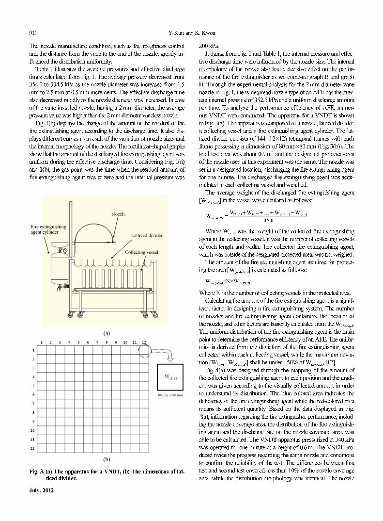
Fig. 4(a) was designed through the mapping of the amount of
the collected fire extinguishing agent to each position and the gradi-
ent was given according to the visually collected amount in order
to understand its distribution. The blue colored area indicates the
deficiency of the fire extinguishing agent while the red-colored area
means its sufficient quantity. Based on the data displayed in Fig.
4(a), information regarding the fire extinguisher performance, includ-
ing the nozzle coverage area, the distribution of the fire extinguish-
ing agent and the discharge rate on the nozzle coverage area, was
able to be calculated. The VNDT apparatus pressurized at 340 kPa
was operated for one minute at a height of 0.6 m. The VNDT pro-
duced twice the progress regarding the same nozzle and conditions
to confirm the reliability of the test. The differences between first
test and second test covered less than 10% of the nozzle coverage
area, while the distribution morphology was identical. The nozzle
W Average( ) = W 1 1,( ) + W 1 2,( ) + … + W n n−1,( ) + W n n,( )
n n×--------------------------------------------------------------------------------
Fig. 3. (a) The apparatus for a VNDT, (b) The dimensions of lat-ticed divider.
An efficient methodology for evaluating the nozzle performance of water-based automatic fire extinguishers 911
Korean J. Chem. Eng.(Vol. 29, No. 7)
distribution data was reliable along with the supply information about
the nozzle performance, including the nozzle coverage area, the dis-
tribution uniformity, and other pertinent information. Fig. 4(b) was
the nozzle coverage area obtained from the VNDT.
The nozzle coverage area (AN) was calculated from the follow-
ing equation:
AN=N×AL
Where N is the number of collecting vessels in the protected area
(88 EA), AL is the area of each latticed divider (80 mm×80 mm).
The nozzle coverage area of this nozzle was 0.56 m2. The weight
of the fire extinguishing agent collected in each vessel was from
33.2 g to 59.9 g, and the average weight of the discharged fire extin-
guishing agent [W(Average)] was 45.4 g. The range of deviation was
from −27% to +32% and the maximum deviation was 32%. These
results indicate that the nozzle has uniform distribution.
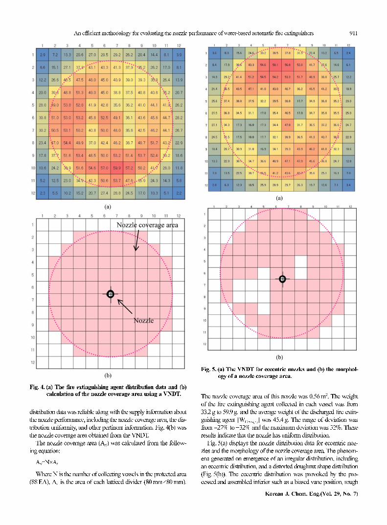
Fig. 5(a) displays the nozzle distribution data for eccentric noz-
zles and the morphology of the nozzle coverage area. The phenom-
ena generated on emergence of an irregular distribution, including
an eccentric distribution, and a distorted doughnut shape distribution
(Fig. 5(b)). The eccentric distribution was provoked by the pro-
cessed and assembled inferior such as a biased vane position, rough
Fig. 4. (a) The fire extinguishing agent distribution data and (b)calculation of the nozzle coverage area using a VNDT.
Fig. 5. (a) The VNDT for eccentric nozzles and (b) the morphol-ogy of a nozzle coverage area.

912 Y. Kim and K. Kwon
July, 2012
surface and an alien substance, etc. The doughnut shape distribu-
tion was induced by the inner structure similar to a simplex-type
swirl structure. The weight of the fire extinguishing agent collected
in each vessel varied from 16.8 g to 58.1 g, and the average weight
of the discharged fire extinguishing agent [W(Average)] was 37.6 g. The
range of deviation was from −55% to +55% and the maximum de-
viation was 55%. The data explains that the nozzle had an irregular
distribution. The AFE having irregular distribution nozzle was not
able to suppress the fire properly, due to the location of the fire source.
The fire extinguishing test for an eccentric nozzle is shown in
Fig. 6, including a photograph and a diagram. The nozzle was in-
stalled at an effective installation height (H) and in the protected
area. The 800 ml soybean oil was heated in a steel frying pan with
a diameter of 300 mm until igniting naturally on the stove. The oil
ignited after 30 minutes, and the AFE discharged within three min-
utes after ignition.
In the case of the pan located as A in Fig. 5(b), after the ignition
and the putting out the pan fire, there was no reignition. In location
B in Fig. 5(b), however, there was a reignition due to a lack of fire
extinguishing agent. These experiments explained the nozzle struc-
ture, and the processed and assembled appearances were very im-
portant factors for the performance efficiency of AFE.
CONCLUSION
The VNDT was conducted to analyze the performance efficiency
of AFE. The correlation between the internal pressure and the amount
of the residual of the fire extinguishing agent according to time was
evaluated by using various sizes and structures of a nozzle. The VNDT
proceeded at an average internal pressure of a fire extinguisher. The
visual nozzle distribution data was designed from the mapping of
the collected fire extinguishing agent in each vessel. The average
weight of the discharged fire extinguishing agent in the unit vessel
was calculated from the nozzle distribution data. The degree of uni-
form distribution was determined by the difference between the aver-
age weight of the discharged fire extinguishing agent and the collected
weight in the each collecting vessel. The required fire extinguish-
ing agent to cover the protected area was also calculated from the
average weight. The effective discharge time and average internal
pressure decrease as the nozzle size increases. The nozzle distribu-
tion data explains the manufacturing condition and the morphology
of its nozzle, while the ineffective nozzle generates an eccentric dis-
tribution. The results have shown that the VNDT serves as the most
powerful method to determine the performance efficiency of AFE.
REFERENCES
1. J. G. Gallup, Professional Safety, 28(Aug) (2004).
2. X. Qiyuan, Y. Hongyong and G. Huiliang, Journal of Fire Sciences,
22, 325 (2004).
3. G. E. Mccreery and C. M. Stoots, Int. J. Multiphase Flow, 22(3), 431
(1996).
4. Y. Zhang, W. Zhu, X. Zhou, J. Qin and G. Liao, Journal of Fire Sci-
ences, 25(January) (2007).
5. Z. Liu and A. K. Kim., Journal of Fire Protection Engineering,
10(3), 32 (2000).
6. Z. Liu and A. K. Kim, Journal of Fire Protection Engineering,
11(February), 16 (2001).
7. B. Cong and G. Liao, Journal of Fire Sciences, 27(March), 101
(2009).
8. C. Beihua, L. Guangxuan and H. Zhen, Journal of Fire Sciences,
27(January), 5 (2009).
9. K. D. Rohr and John R. Hall, Jr., NFPA Fire Analysis and Research,
Quincy, MA (2005).
10. KOFEIS 0101-1, Standards of Model Approval and Inspection Tech-
nology for Automatic Type Fire Extinguishing Units, Notice No.
2010-2 (2010. 1.6).
11. UL 299, Dry Chemical Fire Extinguishers, 2004 Edition.
12. UL 199, Standard for Automatic Sprinklers for Fire-Protection Ser-
vice, 2005 Edition.
Fig. 6. (a) The picture and (b) the diagram of a fire extinguishingtest for an AFE [10].