
An Efficient BIRA Utilizing Characteristics of Spare Pivot...
11
IEEE TRANSACTIONS ON COMPUTER-AIDED DESIGN OF INTEGRATED CIRCUITS AND SYSTEMS, VOL. 38, NO. 3, MARCH 2019 551 An Efficient BIRA Utilizing Characteristics of Spare Pivot Faults Keewon Cho, Young-Woo Lee, Sungyoul Seo, and Sungho Kang , Senior Member, IEEE Abstract—The current growth of micro-semiconductor technologies requires that an effective solution be found to address the yield and reliability issues associated with embedded memories. A common solution is built-in redundancy analysis (BIRA), which is utilized to guarantee reasonable memory yields. The most common form of BIRA is a module that stores and analyzes fault addresses with a 2-D spare architecture. When the performance of BIRA is evaluated, numerous different parameters are considered, such as repair rate, area overhead, and analysis speed. Because there is a tradeoff between these criteria, many BIRA approaches have been studied so that an ideal BIRA can be found. A novel BIRA approach that focuses on a 100% repair rate and a minimal area overhead is proposed in this paper. In the fault collection phase, the proposed BIRA stores only the essential part of fault addresses in content addressable memories (CAMs), with the rest of the fault addresses being stored in spare mem- ories. After the fault collection phase, a redundancy analysis procedure is performed with the minimum amount of fault information that is stored in the proposed CAM structure. By doing so, the proposed BIRA algorithm can repair all repairable faulty memories while maintaining a minimal area overhead. Our experimental results confirm that the proposed approach exhibits outstanding performance for area overhead, especially when compared to other BIRA approaches that have 100% repair rates. Index Terms—Area overhead, built-in redundancy analy- sis (BIRA), redundancy analysis (RA). I. I NTRODUCTION T HE RECENT rapid growth in the manufacturing of micro-semiconductors has facilitated substantial increases with regards to the memory density and capacity of these devices. As memory density has increased, so too has the chance of faults occurring within these memories. As this can leads to significant yield and reliability issues in semiconduc- tor memories, appropriate solutions need to be found. One promising solution is built-in redundancy analysis (BIRA), Manuscript received August 30, 2017; revised December 14, 2017 and February 3, 2018; accepted March 11, 2018. Date of publication March 23, 2018; date of current version February 18, 2019. This work was supported in part by the Ministry of Trade, Industry and Energy under Grant 10067813, and in part by the Korea Semiconductor Research Consortium support program for the development of the future semiconductor device. This paper was recommended by Associate Editor H.-G. Stratigopoulos. (Corresponding author: Sungho Kang.) The authors are with the Department of Electrical and Electronic Engineering, Yonsei University, Seoul 120-749, South Korea (e-mail: [email protected]; [email protected]; [email protected]; [email protected]). Color versions of one or more of the figures in this paper are available online at http://ieeexplore.ieee.org. Digital Object Identifier 10.1109/TCAD.2018.2818725 which analyzes fault addresses that have been detected and repairs them with spare cells that were incorporated for this purpose. Typically, these redundant cells are incorporated in a 2-D spare line architecture comprising row spares and column spares, and the redundancy analysis (RA) for such cells is known to be NP-complete [1]–[3]. As such, repair algorithms have to be carefully selected. The typical performance criteria for BIRAs include repair rate, area overhead, and analysis speed. The repair rate is represented by the percentage of repaired chips in all repairable chips [4], [5]. Many previous BIRA algorithms have looked at achieving a 100% repair rate because this criterion is directly related to the yield of memories [2]–[9]. Area overhead is also important because the areas of chips are limited and larger area overhead leads to more expen- sive chips. Analysis speed, however, has recently been considered to be less important. Previous search-tree-based RA algorithms spent too much time on determining repair solutions because the search mechanisms for determining these solutions were exhaustive [2], [8], [10]–[12]. One way of reducing this time was by reducing the analysis speed. However, recent BIRA approaches have used content address- able memories (CAMs) to achieve significant improvements in analysis speeds [4], [5], [9]. As a result, most of the test and repair times of built-in self-repair (BISR) are taken up by the running of built-in self-test (BIST) [9]. Because there is a tradeoff between the performance criteria of BIRAs, it is impossible for the best result to be obtained for every crite- rion. This inevitably leads to the repair rate and area overhead being prioritized over the analysis speed. There are a variety of different repair algorithms that have different aims; some algorithms are more focused on being simple than on achieving a 100% repair rate, for exam- ple, the repair-most (RM) algorithm [13] utilizes a simple algorithm that allocates spare lines from the faulty line that has the largest number of faults. Although this simplic- ity makes RM easy to implement, it requires the entirety of a failure bitmap to be used. In order to address this weakness, local RM (LRM) [14] has been developed, which utilizes only a small portion of the failure bitmap while maintaining the mechanism of RM. In order to achieve a minimum area overhead, one can use essential spare pivot- ing (ESP) [14], which only stores spare pivot faults and adopts the simple RA algorithm. Both algorithms in [14] obtain fast analysis speed with the low area overhead. However, LRM and ESP cannot guarantee 100% repair rate because their RA algorithms are performed with only partial information 0278-0070 c 2018 IEEE. Personal use is permitted, but republication/redistribution requires IEEE permission. See http://www.ieee.org/publications_standards/publications/rights/index.html for more information.
Transcript of An Efficient BIRA Utilizing Characteristics of Spare Pivot...

IEEE TRANSACTIONS ON COMPUTER-AIDED DESIGN OF INTEGRATED CIRCUITS AND SYSTEMS, VOL. 38, NO. 3, MARCH 2019 551
An Efficient BIRA Utilizing Characteristics ofSpare Pivot Faults
Keewon Cho, Young-Woo Lee, Sungyoul Seo, and Sungho Kang , Senior Member, IEEE
Abstract—The current growth of micro-semiconductortechnologies requires that an effective solution be foundto address the yield and reliability issues associated withembedded memories. A common solution is built-in redundancyanalysis (BIRA), which is utilized to guarantee reasonablememory yields. The most common form of BIRA is a modulethat stores and analyzes fault addresses with a 2-D sparearchitecture. When the performance of BIRA is evaluated,numerous different parameters are considered, such as repairrate, area overhead, and analysis speed. Because there isa tradeoff between these criteria, many BIRA approaches havebeen studied so that an ideal BIRA can be found. A novelBIRA approach that focuses on a 100% repair rate anda minimal area overhead is proposed in this paper. In the faultcollection phase, the proposed BIRA stores only the essentialpart of fault addresses in content addressable memories (CAMs),with the rest of the fault addresses being stored in spare mem-ories. After the fault collection phase, a redundancy analysisprocedure is performed with the minimum amount of faultinformation that is stored in the proposed CAM structure. Bydoing so, the proposed BIRA algorithm can repair all repairablefaulty memories while maintaining a minimal area overhead.Our experimental results confirm that the proposed approachexhibits outstanding performance for area overhead, especiallywhen compared to other BIRA approaches that have 100%repair rates.
Index Terms—Area overhead, built-in redundancy analy-sis (BIRA), redundancy analysis (RA).
I. INTRODUCTION
THE RECENT rapid growth in the manufacturing ofmicro-semiconductors has facilitated substantial increases
with regards to the memory density and capacity of thesedevices. As memory density has increased, so too has thechance of faults occurring within these memories. As this canleads to significant yield and reliability issues in semiconduc-tor memories, appropriate solutions need to be found. Onepromising solution is built-in redundancy analysis (BIRA),
Manuscript received August 30, 2017; revised December 14, 2017and February 3, 2018; accepted March 11, 2018. Date of publicationMarch 23, 2018; date of current version February 18, 2019. This work wassupported in part by the Ministry of Trade, Industry and Energy under Grant10067813, and in part by the Korea Semiconductor Research Consortiumsupport program for the development of the future semiconductor device.This paper was recommended by Associate Editor H.-G. Stratigopoulos.(Corresponding author: Sungho Kang.)
The authors are with the Department of Electrical andElectronic Engineering, Yonsei University, Seoul 120-749, SouthKorea (e-mail: [email protected]; [email protected];[email protected]; [email protected]).
Color versions of one or more of the figures in this paper are availableonline at http://ieeexplore.ieee.org.
Digital Object Identifier 10.1109/TCAD.2018.2818725
which analyzes fault addresses that have been detected andrepairs them with spare cells that were incorporated for thispurpose. Typically, these redundant cells are incorporated ina 2-D spare line architecture comprising row spares andcolumn spares, and the redundancy analysis (RA) for suchcells is known to be NP-complete [1]–[3]. As such, repairalgorithms have to be carefully selected.
The typical performance criteria for BIRAs include repairrate, area overhead, and analysis speed. The repair rateis represented by the percentage of repaired chips in allrepairable chips [4], [5]. Many previous BIRA algorithmshave looked at achieving a 100% repair rate because thiscriterion is directly related to the yield of memories [2]–[9].Area overhead is also important because the areas of chipsare limited and larger area overhead leads to more expen-sive chips. Analysis speed, however, has recently beenconsidered to be less important. Previous search-tree-basedRA algorithms spent too much time on determining repairsolutions because the search mechanisms for determiningthese solutions were exhaustive [2], [8], [10]–[12]. One wayof reducing this time was by reducing the analysis speed.However, recent BIRA approaches have used content address-able memories (CAMs) to achieve significant improvementsin analysis speeds [4], [5], [9]. As a result, most of the testand repair times of built-in self-repair (BISR) are taken up bythe running of built-in self-test (BIST) [9]. Because there isa tradeoff between the performance criteria of BIRAs, it isimpossible for the best result to be obtained for every crite-rion. This inevitably leads to the repair rate and area overheadbeing prioritized over the analysis speed.
There are a variety of different repair algorithms that havedifferent aims; some algorithms are more focused on beingsimple than on achieving a 100% repair rate, for exam-ple, the repair-most (RM) algorithm [13] utilizes a simplealgorithm that allocates spare lines from the faulty line thathas the largest number of faults. Although this simplic-ity makes RM easy to implement, it requires the entiretyof a failure bitmap to be used. In order to address thisweakness, local RM (LRM) [14] has been developed, whichutilizes only a small portion of the failure bitmap whilemaintaining the mechanism of RM. In order to achievea minimum area overhead, one can use essential spare pivot-ing (ESP) [14], which only stores spare pivot faults and adoptsthe simple RA algorithm. Both algorithms in [14] obtain fastanalysis speed with the low area overhead. However, LRMand ESP cannot guarantee 100% repair rate because theirRA algorithms are performed with only partial information
0278-0070 c© 2018 IEEE. Personal use is permitted, but republication/redistribution requires IEEE permission.See http://www.ieee.org/publications_standards/publications/rights/index.html for more information.
552 IEEE TRANSACTIONS ON COMPUTER-AIDED DESIGN OF INTEGRATED CIRCUITS AND SYSTEMS, VOL. 38, NO. 3, MARCH 2019
of faults. All of the algorithms mentioned in this paragraphshow low performance for their repair rates because of theirsimplicities; this is particularly the case when the complexityof the faulty memories is greater.
Comprehensive real-time exhaustive search test and analy-sis (CRESTA) [6] seeks to produce the best possible results interms of the repair rate and analysis speed. CRESTA utilizesmultiple subanalyzers to simultaneously explore all possiblecombinations of spare memories; therefore if repair solu-tions do exist, then CRESTA will find them right afterthe fault collection phase. However, the area overhead ofthe subanalyzers dramatically increases when the numberof spare memories increases. A few attempts have beenmade to utilize CRESTA to reduce the area overhead of thesubanalyzers [15], [16]; however, these algorithms are stillimpractical for use in BIRA algorithms because of the burdenthey place on the chip area.
To consider the balance in performance criteria for BIRAs,several approaches look to utilize a relatively small area over-head, a fast analysis speed, and a 100% repair rate. Selectedfail count comparison (SFCC) [4] and BIRA with branch ana-lyzer (BRANCH) [5] categorize faults into spare pivot faultsand nonspare pivot faults, and store them into separate CAMs.Using the information collected on the faults, an RA procedurecan be executed quickly. However, their fault collection logicslead to a dramatic increase in the area overhead, especiallywhen the number of total spares is large. BIRA algorithmsutilizing address mapping table (AMT) [9] can also store cate-gorized faults into CAMs. Furthermore, this method allows forspare memories to be used during the fault collection phase;this can reduce the usage of some of the storage elements ofthe CAMs. However, the method it uses for utilizing sparememories is complicated, and its area overhead remains large,even when the spare memories are utilized as storage ele-ments. In order to find the repair solution in a single testrun, an on-chip infrastructure for repair analysis using parallelprefix algorithm was proposed [17]. However, area overheadis still room for improvement. In another study, fault-freeregions of a memory array were used instead of CAMs [18].This approach for BIRA looked to replace the conventionalfault-storing structures. However, the mechanism this approachuses for storing faults is unclear, because fault-free regionscannot be predicted. Additionally, this approach can only beperformed under limited circumstances.
Unlike conventional BIRA algorithms utilizing a 2-D sparearchitecture, some BIRA approaches have used modified sparearchitectures in order to augment the number of repairablechips. In the previous studies, multiple spare blocks wereused based on divided word-lines and divided bit-lines inRAMs [19]–[23]. In another study, a memory BISR circuitbased on configurable spares was proposed [24]. In order toimprove the repair efficiency of the BIRA, it configures thesame spare to flexible shapes depending on the failure pattern.Three types of spares were used in some studies to simultane-ously repair multiple memory blocks [25]–[30]. Although theenhanced flexibility of these approaches increases the numberof repairable chips, they generate greater area overhead andrequire complex control procedures.
In order to enhance the area overhead and achieve a 100%repair rate, we have proposed a novel BIRA approach. In orderto minimize the area overhead, only the essential parts of faultaddresses are stored in a new fault-storing CAM structure,with the remainder being stored in spare memories during thefault collection phase. At the end of the fault collection phase,the proposed CAM structure collects the minimum infor-mation needed to perform the RA procedure. The proposedRA process greatly reduces solution search trees by using onlysmall parts of the proposed CAM structure. In Section II ofthis paper, background information is provided. The proposedBIRA algorithm and some simple examples are provided inSection III. Section IV describes experimental results used toevaluate the performance of the proposed BIRA, and Section Vconcludes this paper.
II. BACKGROUND
A. Scheme of the Memory BISR
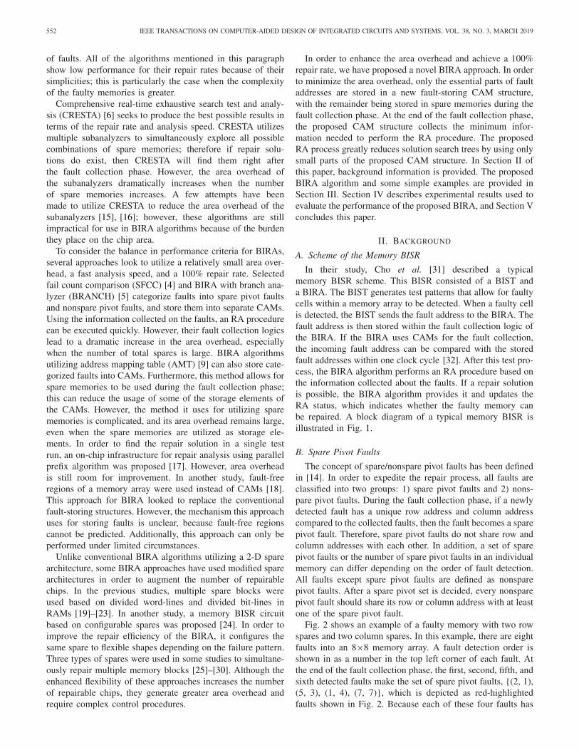
In their study, Cho et al. [31] described a typicalmemory BISR scheme. This BISR consisted of a BIST anda BIRA. The BIST generates test patterns that allow for faultycells within a memory array to be detected. When a faulty cellis detected, the BIST sends the fault address to the BIRA. Thefault address is then stored within the fault collection logic ofthe BIRA. If the BIRA uses CAMs for the fault collection,the incoming fault address can be compared with the storedfault addresses within one clock cycle [32]. After this test pro-cess, the BIRA algorithm performs an RA procedure based onthe information collected about the faults. If a repair solutionis possible, the BIRA algorithm provides it and updates theRA status, which indicates whether the faulty memory canbe repaired. A block diagram of a typical memory BISR isillustrated in Fig. 1.
B. Spare Pivot Faults
The concept of spare/nonspare pivot faults has been definedin [14]. In order to expedite the repair process, all faults areclassified into two groups: 1) spare pivot faults and 2) nons-pare pivot faults. During the fault collection phase, if a newlydetected fault has a unique row address and column addresscompared to the collected faults, then the fault becomes a sparepivot fault. Therefore, spare pivot faults do not share row andcolumn addresses with each other. In addition, a set of sparepivot faults or the number of spare pivot faults in an individualmemory can differ depending on the order of fault detection.All faults except spare pivot faults are defined as nonsparepivot faults. After a spare pivot set is decided, every nonsparepivot fault should share its row or column address with at leastone of the spare pivot fault.
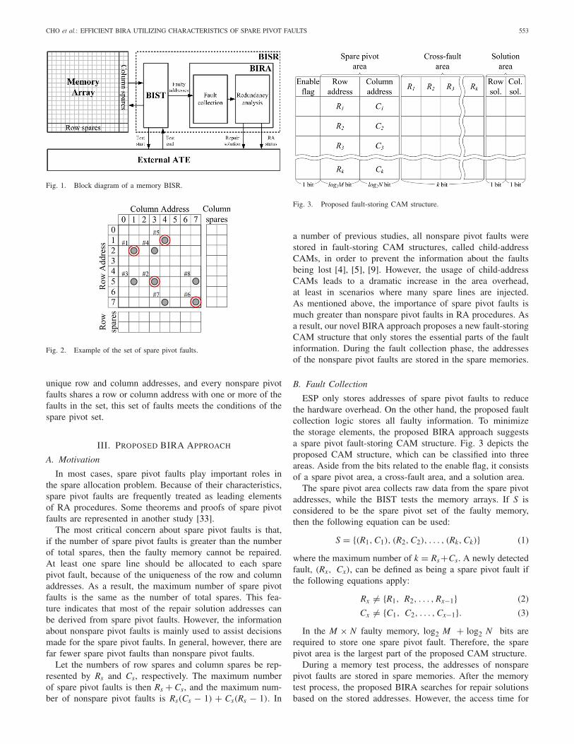
Fig. 2 shows an example of a faulty memory with two rowspares and two column spares. In this example, there are eightfaults into an 8×8 memory array. A fault detection order isshown in as a number in the top left corner of each fault. Atthe end of the fault collection phase, the first, second, fifth, andsixth detected faults make the set of spare pivot faults, {(2, 1),(5, 3), (1, 4), (7, 7)}, which is depicted as red-highlightedfaults shown in Fig. 2. Because each of these four faults has
CHO et al.: EFFICIENT BIRA UTILIZING CHARACTERISTICS OF SPARE PIVOT FAULTS 553
Fig. 1. Block diagram of a memory BISR.
Fig. 2. Example of the set of spare pivot faults.
unique row and column addresses, and every nonspare pivotfaults shares a row or column address with one or more of thefaults in the set, this set of faults meets the conditions of thespare pivot set.
III. PROPOSED BIRA APPROACH
A. Motivation
In most cases, spare pivot faults play important roles inthe spare allocation problem. Because of their characteristics,spare pivot faults are frequently treated as leading elementsof RA procedures. Some theorems and proofs of spare pivotfaults are represented in another study [33].
The most critical concern about spare pivot faults is that,if the number of spare pivot faults is greater than the numberof total spares, then the faulty memory cannot be repaired.At least one spare line should be allocated to each sparepivot fault, because of the uniqueness of the row and columnaddresses. As a result, the maximum number of spare pivotfaults is the same as the number of total spares. This fea-ture indicates that most of the repair solution addresses canbe derived from spare pivot faults. However, the informationabout nonspare pivot faults is mainly used to assist decisionsmade for the spare pivot faults. In general, however, there arefar fewer spare pivot faults than nonspare pivot faults.
Let the numbers of row spares and column spares be rep-resented by Rs and Cs, respectively. The maximum numberof spare pivot faults is then Rs + Cs, and the maximum num-ber of nonspare pivot faults is Rs(Cs − 1) + Cs(Rs − 1). In
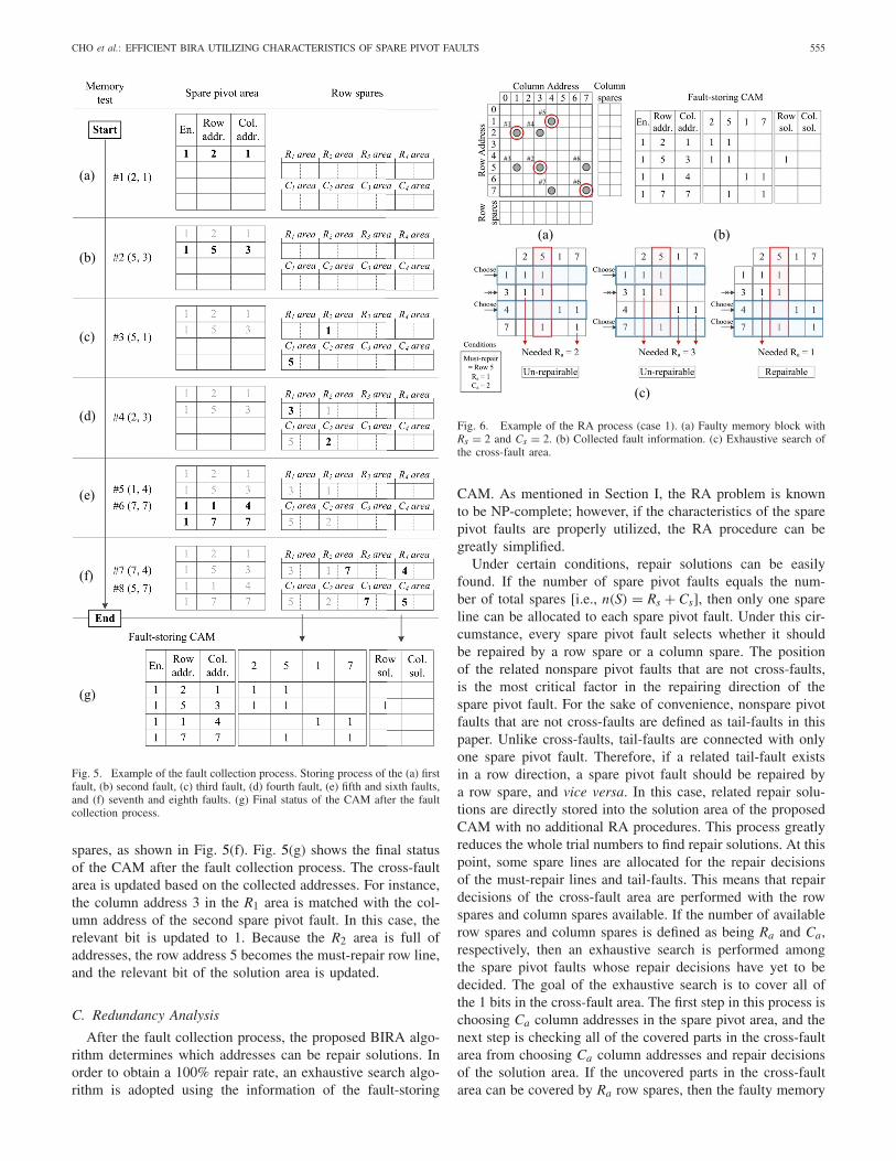
Fig. 3. Proposed fault-storing CAM structure.
a number of previous studies, all nonspare pivot faults werestored in fault-storing CAM structures, called child-addressCAMs, in order to prevent the information about the faultsbeing lost [4], [5], [9]. However, the usage of child-addressCAMs leads to a dramatic increase in the area overhead,at least in scenarios where many spare lines are injected.As mentioned above, the importance of spare pivot faults ismuch greater than nonspare pivot faults in RA procedures. Asa result, our novel BIRA approach proposes a new fault-storingCAM structure that only stores the essential parts of the faultinformation. During the fault collection phase, the addressesof the nonspare pivot faults are stored in the spare memories.
B. Fault Collection
ESP only stores addresses of spare pivot faults to reducethe hardware overhead. On the other hand, the proposed faultcollection logic stores all faulty information. To minimizethe storage elements, the proposed BIRA approach suggestsa spare pivot fault-storing CAM structure. Fig. 3 depicts theproposed CAM structure, which can be classified into threeareas. Aside from the bits related to the enable flag, it consistsof a spare pivot area, a cross-fault area, and a solution area.
The spare pivot area collects raw data from the spare pivotaddresses, while the BIST tests the memory arrays. If S isconsidered to be the spare pivot set of the faulty memory,then the following equation can be used:
S = {(R1, C1), (R2, C2), . . . , (Rk, Ck)} (1)
where the maximum number of k = Rs+Cs. A newly detectedfault, (Rx, Cx), can be defined as being a spare pivot fault ifthe following equations apply:
Rx �= {R1, R2, . . . , Rx−1} (2)
Cx �= {C1, C2, . . . , Cx−1}. (3)
In the M × N faulty memory, log2 M + log2 N bits arerequired to store one spare pivot fault. Therefore, the sparepivot area is the largest part of the proposed CAM structure.
During a memory test process, the addresses of nonsparepivot faults are stored in spare memories. After the memorytest process, the proposed BIRA searches for repair solutionsbased on the stored addresses. However, the access time for

554 IEEE TRANSACTIONS ON COMPUTER-AIDED DESIGN OF INTEGRATED CIRCUITS AND SYSTEMS, VOL. 38, NO. 3, MARCH 2019
the spare memories is much greater than that of the CAMsbecause of the differences in the search mechanism. In order tomake the RA process more efficient, the proposed BIRA algo-rithm accesses the spare memories at the end of a memorytest process and stores the necessary information into both thecross-fault and solution areas.
As mentioned in Section II-B, each nonspare pivot faultshares a row or column address with at least another sparepivot fault. In a repair decision for a spare pivot fault, it iscrucial that the related nonspare pivot faults are located eitheron the same row line or column line as the spare pivot fault,or even on both the same row and column lines. However,a certain type of nonspare pivot fault disturbs the repair deci-sion by simultaneously sharing its row address with one sparepivot fault and its column address with another spare pivotfault; this is defined as a cross-fault in this paper. For a 100%repair rate, the information of cross-faults should be high-lighted, because it affects the repair decisions of two differentspare pivot faults. If C is a set of cross-fault candidates, thenthe following equation can be used:
C = {(Ri, Cj)|1 ≤ i ≤ k, 1 ≤ j ≤ k, i �= j
}. (4)
The cross-fault area is a combination of two sets, S andC. In order to detect all of the cross-faults in a memory, Sshould be settled first. However, because the order in whichthe faults are detected cannot be predicted, the process fordetecting cross-faults is done at the end of a memory testprocess. Once a nonspare pivot fault is contained within C, therelevant bit of the cross-fault area becomes 1. In RA processes,S is also marked as a cross-fault area.
The solution area indicates the repair solution that will beused for the faulty memory. When the repair solution is con-firmed, the relevant bit becomes 1 for the memory repairprocess.
Basically, row spare memories are used to store theaddresses of nonspare pivot faults, because they are moreconvenient to access than column spare memories. Columnspare memories also can be utilized as storage elements incase of the number of required bits for storing nonspare pivotfaults is greater than the number of bits of row spare memo-ries. The detailed conditions of using column spare memorieswill be explained in Section IV. The storage process is rel-atively straightforward; once the number of row spares andcolumn spares are settled, certain lengths of bits are assignedto each element of S. Then, whenever a nonspare pivot fault isdetected, its address information is stored into the preassignedspace.
The concept of must-repair lines [2], [13] needs to be intro-duced prior to any explanation being made about the usageof row spares. In general, a faulty row line can be repairedby either a row spare or several column spares. However,if a faulty row line has more faults than there are columnspares available, then it can only be repaired by a row spare.Similarly, if a faulty column line has more faults than there arerow spares available, then a column spare must be allocatedto this faulty line. Because repairing solutions of these kindsof faulty lines are fixed, they are called must-repair lines.
Fig. 4. Usage of the row spare memories.
When a spare pivot (R1, C1) is considered, related nonsparepivot faults are divided and stored into either the R1 area orthe C1 area. Faults that share their row address with (R1, C1)
belong to the R1 area. The length of the R1 area dependson the number of column spares. Maximum Cs faults can bestored in a R1 area considering the concept of must-repairlines. If the area is full, then the row address R1 is desig-nated as a solution address, because this row address meatsthe must-repair condition. Only column addresses are storedin the R1 area, because we already know that the row addressis R1. The column addresses of the R1 area are expressed asCR1_1, CR1_2, . . . , CR1_Cs . The same concept applies to the C1area. Fig. 4 is a schematic illustration of how row spare mem-ories are used. If a nonspare pivot fault is detected, then theproposed BIRA algorithm searches the appropriate area andstores the address information.
Detailed information about the fault collection process ofthe faulty memory shown in Fig. 2 is depicted in Fig. 5.When the BIST starts the memory test, the spare pivot area ofthe proposed CAM and the row spares store the necessaryfault addresses whenever a fault is detected. Once the lastfault is detected, the final status of the proposed CAM isupdated.
Initially, the faulty cell (2, 1) is detected. Because thespare pivot area has yet to store anything, (2, 1) becomesthe first spare pivot fault [i.e., (R1, C1) = (2, 1)]. It is storedinto the spare pivot area as shown in Fig. 5(a). The seconddetected fault is (5, 3); because row 5 and column 3 areunique addresses in the spare pivot area, this fault is alsostored into the spare pivot area as that shown in Fig. 5(b) [i.e.,(R2, C2) = (5, 3)]. The third detected fault is (5, 1), andit shares a row address with the second fault and a columnaddress with the first fault, respectively. So the row sparesstore its column address to the R2 area and its row address tothe C1 area, as shown in Fig. 5(c). This fault is related to thetwo spare pivot faults at the same time. As a result, the thirddetected fault is defined as a cross-fault. As with the thirdfault, the fourth detected fault, (2, 3), shares its addresseswith the first and second fault. As such, the addresses offourth fault are stored into the row spares, as shown inFig. 5(d) and it also becomes a cross-fault. The fifth and sixthdetected faults have unique row and column addresses amongthe spare pivot faults. As such, the fifth and sixth faults arestored into the spare pivot area, as shown in Fig. 5(e) [i.e.,(R3, C3) = (1, 4), (R4, C4) = (7, 7)]. The seventh andeighth detected faults are (7, 4) and (5, 7), respectively. Bothfaults meet the cross-fault condition and are stored into row
CHO et al.: EFFICIENT BIRA UTILIZING CHARACTERISTICS OF SPARE PIVOT FAULTS 555
(a)
(b)
(c)
(d)
(e)
(f)
(g)
Fig. 5. Example of the fault collection process. Storing process of the (a) firstfault, (b) second fault, (c) third fault, (d) fourth fault, (e) fifth and sixth faults,and (f) seventh and eighth faults. (g) Final status of the CAM after the faultcollection process.
spares, as shown in Fig. 5(f). Fig. 5(g) shows the final statusof the CAM after the fault collection process. The cross-faultarea is updated based on the collected addresses. For instance,the column address 3 in the R1 area is matched with the col-umn address of the second spare pivot fault. In this case, therelevant bit is updated to 1. Because the R2 area is full ofaddresses, the row address 5 becomes the must-repair row line,and the relevant bit of the solution area is updated.
C. Redundancy Analysis
After the fault collection process, the proposed BIRA algo-rithm determines which addresses can be repair solutions. Inorder to obtain a 100% repair rate, an exhaustive search algo-rithm is adopted using the information of the fault-storing
(a) (b)
(c)
Fig. 6. Example of the RA process (case 1). (a) Faulty memory block withRs = 2 and Cs = 2. (b) Collected fault information. (c) Exhaustive search ofthe cross-fault area.
CAM. As mentioned in Section I, the RA problem is knownto be NP-complete; however, if the characteristics of the sparepivot faults are properly utilized, the RA procedure can begreatly simplified.
Under certain conditions, repair solutions can be easilyfound. If the number of spare pivot faults equals the num-ber of total spares [i.e., n(S) = Rs + Cs], then only one spareline can be allocated to each spare pivot fault. Under this cir-cumstance, every spare pivot fault selects whether it shouldbe repaired by a row spare or a column spare. The positionof the related nonspare pivot faults that are not cross-faults,is the most critical factor in the repairing direction of thespare pivot fault. For the sake of convenience, nonspare pivotfaults that are not cross-faults are defined as tail-faults in thispaper. Unlike cross-faults, tail-faults are connected with onlyone spare pivot fault. Therefore, if a related tail-fault existsin a row direction, a spare pivot fault should be repaired bya row spare, and vice versa. In this case, related repair solu-tions are directly stored into the solution area of the proposedCAM with no additional RA procedures. This process greatlyreduces the whole trial numbers to find repair solutions. At thispoint, some spare lines are allocated for the repair decisionsof the must-repair lines and tail-faults. This means that repairdecisions of the cross-fault area are performed with the rowspares and column spares available. If the number of availablerow spares and column spares is defined as being Ra and Ca,respectively, then an exhaustive search is performed amongthe spare pivot faults whose repair decisions have yet to bedecided. The goal of the exhaustive search is to cover all ofthe 1 bits in the cross-fault area. The first step in this process ischoosing Ca column addresses in the spare pivot area, and thenext step is checking all of the covered parts in the cross-faultarea from choosing Ca column addresses and repair decisionsof the solution area. If the uncovered parts in the cross-faultarea can be covered by Ra row spares, then the faulty memory
556 IEEE TRANSACTIONS ON COMPUTER-AIDED DESIGN OF INTEGRATED CIRCUITS AND SYSTEMS, VOL. 38, NO. 3, MARCH 2019
can be repaired. The final step is to store the repair solutioninto the solution area.
If the number of spare pivot faults is less than the number oftotal spares [i.e., n(S) < Rs +Cs], then the number of solutionsearching cases increases. In this condition, the use of sparelines becomes more flexible; for example, both a row spareand column spare can be allocated to one spare pivot fault.In addition, it becomes possible for a spare line to be directlyattributable to a tail-fault without the need to go through therelated spare pivot fault. Therefore, if needed, the informationfor the tail-faults can added to the cross-fault area in order tofind the repair solution. The basic mechanism of an exhaustivesearch in this condition is similar to the previous one; however,in this case, the exhaustive search was performed for all of thespare pivot faults. The first step is to check the tail-faults andstore the related solution into the solution area. At this point,if there is no available row spare, then the related columnaddress of the tail-fault can be stored into the CAM so that theproposed BIRA seeks the possibility of repairing this tail-faultusing column spares. However, if there is no available columnspare, the related row address of the tail-fault is stored into theCAM in the same manner. The second step is to choose theCa column addresses in the spare pivot area. Even if a sparepivot fault is already repaired by a spare row, the columnaddress of the fault should be considered in the second stepbecause of the flexibility of the spare lines. After that, a checkis performed in which it is determined if the uncovered partsof the cross-fault area can be covered by Ra row spares. If allof the 1 bits in the cross-fault area can be covered, then therepair solution is stored into the solution area.
Fig. 6 shows the detailed RA process of the faulty memoryin Fig. 2. Fig. 6(a) shows a spare pivot set after the fault col-lection phase. There are four spare pivot faults in the faultymemory depicted within this set. Because the number of totalspares is four in this example, only one spare line can be allo-cated to each spare pivot fault. A close look at the nonsparepivot faults reveals that there is no tail-fault in this exam-ple; every nonspare pivot fault is simultaneously connectedwith two spare pivot faults. As a result, there are four sparepivot faults and four cross-faults in this faulty memory block.Fig. 6(b) depicts the collected fault information. The cross-fault area covers all of the information about the spare pivotfaults and cross-faults. During the fault collection process,must-repair lines are detected so that the solution of the sparepivot fault (5, 3) is decided by the repairing row address 5.Following this, an exhaustive search is performed based onthe collected information in the cross-fault area, as shown inFig. 6(c). Because one row spare is already allocated, the num-ber of available row spares is one, and the number of availablecolumn spares is two. The spare pivot faults whose repair deci-sions have yet to be decided in this example are (2, 1), (1, 4),and (7, 7). A total of three search cases are then generatedby the choosing of two column addresses in the spare pivotarea (i.e., 3C2 = 2). If the column addresses 1 and 4 arechosen, then faults (2, 3) and (7, 7) should be repaired bythe row spares. Therefore, at least two row spares are neededto repair this faulty memory. However, because only one rowspare is left, this faulty memory cannot be repaired. Similarly,
if column addresses 1 and 7 are chosen, the faulty memorycannot be repaired, because it needs three available row spares.If column addresses 4 and 7 are chosen, faults (2, 1) and(2, 3) are left, and these faults can be repaired by one rowspare. Therefore, the repair solution is to repair row addresses2 and 5 and column addresses 4 and 7.
Fig. 7 shows the RA process of a faulty memory that hasthe same fault pattern as the faulty memory of Fig. 6; how-ever, the fault detection order and spare structures are different.There are three spare pivot faults in this example, as shownin Fig. 7(a). From the definition, faults (2, 3), (1, 4), and(5, 3) become tail-faults. These faults are stored in the R1area, C2 area, and R3 area, respectively. However, the fault(1, 4) cannot be covered by a column spare, because there isno available column spare. As a result, the related row address1 is stored into the CAM, as shown in Fig. 7(b). In order torepair the rest of the tail-faults and the must-repair line, rowaddresses 2 and 5 have to be repaired, and the related infor-mation is stored into the solution area. Because there is nocolumn spare, only one case is considered in the exhaustivesearch, as shown in Fig. 7(c). To conclude, therefore, the repairsolution can be determined to have to repair row addresses 1,2, 5, and 7.
IV. EXPERIMENTAL RESULTS
A simulation tool made in the computing language C wasused in order to measure the performance of the proposedBIRA algorithm. When the assorted inputs, such as memorysize, the numbers of row and column spares, the number offaults, and the number of trials were entered into the simu-lation, the performance criteria of the BIRA algorithm, suchas the repair rate, the number of storage elements, and thesolution data, were generated.
Prior to the performance estimation of the proposedBIRA algorithm, a comparison was made between thearea allocated for row spares and the bits required for storingnonspare pivot faults. From Fig. 4, the number of requiredbits for storing nonspare pivot faults can be decided using thefollowing equation:
Arequired = log2 M × Rs × (Rs + Cs)
+ log2 N × Cs × (Rs + Cs) (7)
where M is the number of rows of a memory array andN is the number of columns of a memory array, respec-tively. Additionally, the provided bits of the row spares canbe expressed as in the following equation:
Arow_spares = M × Rs. (8)
If all of the row spares turn out to be faulty lines, or there areno row spares in the first place, then Rs = 0. In such a scenario,the spare allocation problem becomes a 1-D RA problem,because only the column spares are used for the RA processes.Therefore, whenever a faulty cell is detected, the columnaddress of the faulty cell becomes the repair solution.
The worst-case scenario occurs when there is only one rowspare for a small size of M. In such a case, the number of bitsrequired may exceed the number of bits of row spares when the

CHO et al.: EFFICIENT BIRA UTILIZING CHARACTERISTICS OF SPARE PIVOT FAULTS 557
(a) (b)
(c)
Fig. 7. Example of the RA process (case 2). (a) Faulty memory block withRs = 4. (b) Collected fault information and storing process for the tail-fault.(c) Exhaustive search of the cross-fault area.
number of column spares increases. Fig. 8 shows a comparisonbetween the number of bits of row spares and the bits requiredas functions of different memory sizes. Each dotted line rep-resents the number of bits of the row spares for differentmemory sizes, and each solid line represents the change inthe bits required per unit increase in Cs when the number ofrow spares is fixed to 1. The graph indicates that the positionof the dotted line on the y-axis dramatically increases whenthe size of the memory row line increases. However, the posi-tions of the solid lines on the y-axis are relatively small as thenumber of spares increases. As such, the numbers of bits pro-vided by a row spare are typically larger than required bits forstoring nonspare pivot faults. However, graph shows that thesolid red line overtakes the dotted red line when the numberof column spares is above 6. Under these circumstances, thenumber of required bits for storing faulty addresses is greaterthan the number of bits of row spare memories. Therefore, col-umn spare memories are used to store addresses of nonsparepivot faults in these spare structures. However, these circum-stances are unusual, because these kinds of unbalanced sparestructures are rare.
Fig. 9 shows a comparison between the number of bits ofthe row spares and the bits required for various conditionswhen the size of the memory row line is set to 512. Becausethe number of bits the row spares is only dependent on Mand Rs as shown in (8), the numbers of bits provided in therow spares stay the same when the size of the memory col-umn line increases. The graph indicates that the number ofbits of the row spares can cover the bits required for storingnonspare pivot faults under various conditions even at smallvalues of M. From (8) and (9), we can tell that the bits requiredexceed the bits provided at around Rs = 13 and Cs = 13; how-ever, RA algorithms usually do not consider a large numberof spares, because the complexity of RA problems increase
Fig. 8. Comparison between the number of bits of the row spares and the bitsrequired as functions of different memory sizes and column spares (Rs = 1).
Fig. 9. Comparison between the number of bits of the row spares and thebits required as functions of different memory sizes and spares (M = 512).
exponentially. Additionally, the maximum limit on the numberof spares rapidly increases when the size of a memory row lineincreases. Therefore, in general, the proposed BIRA algorithmcan store all fault information and not experience any problemswhile doing so.
For the estimation of the area overhead of BIRA algorithms,recent studies have looked to compare the number of storageelements of assorted BIRA algorithms instead of the actualsize of the BIRA modules [4], [5], [9], [14]. This storage ele-ments comparison method is preferred, because it is difficultto implement all of the BIRA algorithms; this is particularlytrue when the structure of the RA logic varies depending onthe row and column spares. However, the area overhead ofthe fault collection logic can be easily estimated by compar-ing the number of storage elements. If multiple memory arraysare assumed to be injected, then the area of the storage require-ments accounts for the majority of a BIRA module, becauseeach memory block requires a separate fault collection logic.Therefore, the number of storage elements can be used asa pointer for the area overhead of the BIRA algorithms. Thenumber of storage elements of several BIRA algorithms hasalready been discussed elsewhere [4], [5], [9], [14].
The number of storage elements of each BIRA algorithmcan be expressed using (9)–(18). Aspare_register denotes the
558 IEEE TRANSACTIONS ON COMPUTER-AIDED DESIGN OF INTEGRATED CIRCUITS AND SYSTEMS, VOL. 38, NO. 3, MARCH 2019
number of storage elements for a repair solution, and ARM,ALRM, AESP, ACRESTA, AISF, ASFCC, ABRANCH, AAMT, andAPROPOSED denote the number of storage elements of eachBIRA algorithm
Aspare_register = [(⌈log2 M
⌉ + 1) × Rs
+ [(⌈log2 N
⌉ + 1) × Cs
](9)
ARM = M × N (10)
ALRM = m × n + [⌈log2 M
⌉ + 1 + ⌈log2 (n + 1)
⌉] × m
+ [⌈log2 N
⌉ + 1 + ⌈log2 (m + 1)
⌉] × n
+ Aspare_register (11)
where m = Rs × (Cs + 1) + Rs and n = Cs × (Rs + 1) + Cs
AESP = (Rs + Cs) × (⌈log2 M
⌉ + 1 + ⌈log2 N
⌉ + 1)
+ Aspare_register (12)
ACRESTA = (Rs + Cs)!
(Rs! × Cs!)× Aspare_register (13)
AISF, A[17] = 2 × Rs × Cs × (⌈log2 M
⌉ + ⌈log2 N
⌉ + 1)
+ 2 × Rs × Cs × (⌈log2 Rs
⌉ + ⌈log2 Cs
⌉)
+ Aspare_register (14)
ASFCC = (Rs + Cs) × (⌈log2 M
⌉ + ⌈log2 N
⌉ + 2)
+(Rs + Cs) × (⌈log2 Rs
⌉ + ⌈log2 Cs
⌉)
+ [Rs × (Cs − 1) + Cs × (Rs − 1)]
× [⌈log2 (max(M, N) )
⌉ + ⌈log2 (Rs + Cs)
⌉ + 2]
+ Aspare_register (15)
ABRANCH = (Rs + Cs) × (⌈log2 M
⌉ + ⌈log2 N
⌉ + 3)
+ [Rs × (Cs − 1) + Cs × (Rs − 1)]
× [⌈log2 (max(M, N) )
⌉ + ⌈log2 (Rs + Cs)
⌉ + 2]
(16)
AAMT = 2 × Rs × Cs × [⌈log2(Rs × (Cs + 1))
⌉
+ ⌈log2(Cs × (Rs + 1)
⌉ + 1]
+ Rs × ⌈log2(Rs × (Cs + 1))
⌉
+ Cs × ⌈log2(Cs × (Rs + 1))
⌉(17)
AProposed = (Rs + Cs)
× [⌈log2 M
⌉ + ⌈log2 N
⌉ + Rs + Cs + 3]. (18)
Equation (18) can be derived from the proposed fault-storingCAM structure depicted in Fig. 3. Similarly to BRANCH, theproposed BIRA algorithm does not need the term Aspare_register,because the information about the repair solution is stored inthe solution area of the fault-storing CAM.
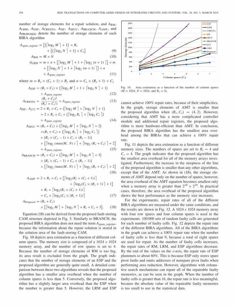
Fig. 10 depicts area estimation as a function of different col-umn spares. The memory size is composed of a 1024 × 1024memory array, and the number of row spares is set to 4.Because the number of storage elements of RM is too big,its area result is excluded from the graph. The graph indi-cates that the number of storage elements of an ESP and theproposed algorithm are generally quite small. A detailed com-parison between these two algorithms reveals that the proposedalgorithm has a smaller area overhead when the number ofcolumn spares is less than 5. Conversely, the proposed algo-rithm has a slightly larger area overhead than the ESP whenthe number is greater than 5. However, the LRM and ESP
Fig. 10. Area estimation as a function of the number of column spares(M = 1024, N = 1024, and Rs = 4).
cannot achieve 100% repair rates, because of their simplicities.In the graph, storage elements of AMT is smaller thanthe proposed algorithm when (Rs, Cs) = (4, 2). However,considering that AMT has a more complicated controllermodule and additional repair registers, the proposed algo-rithm is more hardware-efficient than AMT. In conclusion,the proposed BIRA algorithm has the smallest area over-head among the BIRAs that can achieve a 100% repairrate.
Fig. 11 depicts the area estimation as a function of differentmemory sizes. The numbers of spares are set to Rs = 4 andCs = 4. The graph indicates that the proposed algorithm hasthe smallest area overhead for all of the memory arrays inves-tigated. Furthermore, the increase in the steepness of the lineof the proposed algorithm is smaller than any other algorithms,except that of the AMT. As shown in (16), the storage ele-ments of AMT depend only on the number of spares; however,the area overhead of the AMT equation becomes smallest onlywhen a memory array is greater than 219 × 219. In practicalcases, therefore, the area overhead of the proposed algorithmshows the best performance as the memory size increases.
For the experiments, repair rates of all of the differentBIRA algorithms are measured under the same conditions, andthe results are shown in Fig. 12. A 1024×1024 memory arraywith four row spares and four column spares is used in theexperiments. 100 000 sets of random faulty cells are generatedfor each number of faulty cells. Fig. 12 depicts the repair rateof the different BIRA algorithms. All of the BIRA algorithmsin the graph can achieve a 100% repair rate when the numberof faulty cells is less than 9, because a total of eight sparesare used for repair. As the number of faulty cells increases,the repair rates of RM, LRM, and ESP algorithms decrease.By the end of the values on the x-axis, the repair rate of ESPplummets to about 60%. This is because ESP only stores sparepivot faults and omits addresses of nonspare pivot faults whenperforming area reduction. However, algorithms with exhaus-tive search mechanisms can repair all of the repairable faultymemories, as can be seen in the graph. When the number offaulty cells is greater than 16, the repair rate is less meaningful,because the absolute value of the repairable faulty memoriesis too small to use in the statistical data.

CHO et al.: EFFICIENT BIRA UTILIZING CHARACTERISTICS OF SPARE PIVOT FAULTS 559
Fig. 11. Area estimation as a function of memory size (Rs = 4 and Cs = 4).
Fig. 12. Repair rate of the various BIRA algorithms (M = 1024, N = 1024,Rs = 4, and Cs = 4).
In order to compare run time with other BIRA methods, therequiring clock cycles for RA logic have been measured usingthe simulation tool. Since the fault collection process is per-formed during the BIST operation, the experimental results ofclock cycles do not include the requiring clock cycles for faultcollection logic. Fig. 13 shows the average clock cycles of thevarious BIRA algorithms when M = 1024, N = 1024, Rs = 4,
and Cs = 4. Ten thousand sets of random faulty cells aregenerated for each number of faulty cells. When the numberof faulty cells is less than 9, clock cycles do not repre-sent much to the run time comparison because all of theBIRA algorithms can repair all faulty memories in less time.At first, clock cycles of most BIRA algorithms increase asthe number of faulty cells increases, but decrease sharply atthe end of graphs. This is because a large number of faultymemories are judged as un-repairable memories during thefault collection phase where many faulty cells are injected.Graphs indicate that clock cycles of ESP and CRESTA main-tain zero clock cycles since these two algorithms get repairsolutions during the fault collection process. Because of itssimple algorithm, clock cycles of RM and LRM also main-tain low values throughout the experiments. BRANCH showsthe best performance in clock cycles among BIRA algo-rithms which achieve 100% repair rate, except CRESTA. In
Fig. 13. Average clock cycles of the various BIRA algorithms (M = 1024,N = 1024, Rs = 4, and Cs = 4).
Fig. 14. Comparison of overall performance of BIRA algorithm (M = 1024,N = 1024, Rs = 4, and Cs = 4).
general, clock cycles of the proposed algorithm are smallerthan those of [17], ISF, SFCC, and AMT, but slightly biggerthan BRANCH. However, advancements in the area over-head and repair rate parameters were the main purpose ofthe BIRA approach proposed in this paper; analysis speed,however, was only considered to be a minor factor, as dis-cussed in Section I. Despite the main purpose of the proposedalgorithm, analysis speed of the proposed BIRA is not muchslower than that of BRANCH. When the number of faultycells is greater than 16, the clock cycle comparison is lessmeaningful because the absolute value of the repairable faultymemories is too small.
If we were to assume that an ideal BIRA exists, wewould assume that it could repair all of the repairablefaulty memories and have no area overhead and RA timeat all. Fig. 14 shows the comparison of overall performanceof various BIRA algorithms. Concerning area overhead,the proposed algorithm and ESP come closest to emu-lating the ideal BIRA. However, when the repair rate iscombined, there are greater discrepancies between the ESPand an ideal BIRA algorithm. CRESTA shows the fastestRA time but its storage elements are too large. ExceptCRESTA, BRANCH and the proposed BIRA algorithm hasrelatively fast RA time among the algorithms with 100%

560 IEEE TRANSACTIONS ON COMPUTER-AIDED DESIGN OF INTEGRATED CIRCUITS AND SYSTEMS, VOL. 38, NO. 3, MARCH 2019
repair rate. However, the proposed BIRA algorithm uses abouta half of the storage elements in comparison to those ofBRANCH. As a result, the proposed BIRA approach can besaid to be the one that most closely resembles an ideal BIRAalgorithm.
V. CONCLUSION
This paper carries out a detailed investigation of spare pivotfaults, and it proposes an efficient BIRA approach using thecharacteristics of these faults. Unlike conventional parent-childCAM structures, the CAM structure proposed by this papermainly focuses on spare pivot addresses so that the proposedBIRA algorithm can acquire the smallest area overhead amongthe BIRA algorithms that have a 100% repair rate. In orderto prevent fault information from being lost, spare memoriesare utilized during the fault collection process. On the basis ofthe collected information, an exhaustive search is performed inorder to guarantee a 100% repair rate. In conclusion, we expectthat the proposed BIRA approach will prove to be a practi-cal solution to the yield and reliability problems commonlyencountered in commodity memories.
REFERENCES
[1] S.-Y. Kuo and W. K. Fuchs, “Efficient spare allocation for reconfig-urable arrays,” IEEE Des. Test Comput., vol. DTC-4, no. 1, pp. 24–31,Feb. 1987.
[2] J. R. Day, “A fault-driven, comprehensive redundancy algorithm,” IEEEDes. Test Comput., vol. DTC-2, no. 3, pp. 35–44, Jun. 1985.
[3] M.-H. Yang, H. Cho, W. Kang, and S. Kang, “EOF: Efficient built-in redundancy analysis methodology with optimal repair rate,” IEEETrans. Comput.-Aided Design Integr. Circuits Syst., vol. 29, no. 7,pp. 1130–1135, Jul. 2010.
[4] W. Jeong, I. Kang, K. Jin, and S. Kang, “A fast built-in redundancyanalysis for memories with optimal repair rate using a line-based searchtree,” IEEE Trans. Very Large Scale Integr. (VLSI) Syst., vol. 17, no. 12,pp. 1665–1678, Dec. 2009.
[5] W. Jeong, J. Lee, T. Han, K. Lee, and S. Kang, “An advanced BIRA formemories with an optimal repair rate and fast analysis speed by usinga branch analyzer,” IEEE Trans. Comput.-Aided Design Integr. CircuitsSyst., vol. 29, no. 12, pp. 2014–2026, Dec. 2010.
[6] T. Kawagoe et al., “A built-in self-repair analyzer (CRESTA) forembedded DRAMs,” in Proc. Int. Test Conf., Oct. 2000, pp. 567–574.
[7] H.-Y. Lin, F.-M. Yeh, and S.-Y. Kuo, “An efficient algorithm for spareallocation problems,” IEEE Trans. Rel., vol. 55, no. 2, pp. 369–378,Jun. 2006.
[8] P. Öhler, S. Hellebrand, and H.-J. Wunderlich, “An integrated built-intest and repair approach for memories with 2D redundancy,” in Proc.ETS, May 2007, pp. 91–96.
[9] W. Kang, H. Cho, J. Lee, and S. Kang, “A BIRA for memorieswith an optimal repair rate using spare memories for area reduction,”IEEE Trans. Very Large Scale Integr. (VLSI) Syst., vol. 22, no. 11,pp. 2336–2349, Nov. 2014.
[10] W. K. Huang, Y.-N. Shen, and F. Lombardi, “New approaches for therepairs of memories with redundancy by row/column deletion for yieldenhancement,” IEEE Trans. Comput.-Aided Design Integr. Circuits Syst.,vol. 9, no. 3, pp. 323–328, Mar. 1990.
[11] R. Libeskind-Hadas and C. L. Liu, “Fast search algorithms for reconfig-uration problems,” in Proc. Int. Workshop Defect Fault Tolerance VLSISyst., 1991, pp. 260–273.
[12] D. M. Blough, “Performance evaluation of a reconfiguration-algorithmfor memory arrays containing clustered faults,” IEEE Trans. Rel., vol. 45,no. 2, pp. 274–284, Jun. 1996.
[13] M. Tarr, D. Boudreau, and R. Murphy, “Defect analysis system speedstest and repair of redundancy memories,” Electronics, vol. 57, no. 1,pp. 175–179, Jan. 1984.
[14] C.-T. Huang, C.-F. Wu, J.-F. Li, and C.-W. Wu, “Built-in redundancyanalysis for memory yield improvement,” IEEE Trans. Rel., vol. 52,no. 4, pp. 386–399, Dec. 2003.
[15] W. Jeong, T. Han, and S. Kang, “An advanced BIRA using parallelsub-analyzers for embedded memories,” in Proc. ISOCC, Nov. 2009,pp. 249–252.
[16] P. Habiby and R. N. Asli, “An improved BIRA for memories withoptimal repair rate using a flipping analyzer,” in Proc. ICEE, May 2012,pp. 188–193.
[17] J. Chung, J. Park, J. A. Abraham, E. Byun, and C.-J. Woo, “Reducingtest time and area overhead of an embedded memory array built-inrepair analyzer with optimal repair rate,” in Proc. IEEE VLSI Test Symp.,Apr. 2010, pp. 33–38.
[18] C.-H. Oh, S.-E. Kim, and J.-S. Yang, “A BIRA using fault-free memoryregion for area reduction,” in Proc. APCCAS, Oct. 2016, pp. 480–482.
[19] J.-F. Li, J.-C. Yeh, R.-F. Huang, and C.-W. Wu, “A built-in self-repairdesign for RAMs with 2-D redundancy,” IEEE Trans. Very Large ScaleIntegr. (VLSI) Syst., vol. 13, no. 6, pp. 742–745, Jun. 2005.
[20] S.-K. Lu, Y.-C. Tsai, C.-H. Hsu, K.-H. Wang, and C.-W. Wu, “Efficientbuilt-in redundancy analysis for embedded memories with 2-D redun-dancy,” IEEE Trans. Very Large Scale Integr. (VLSI) Syst., vol. 14, no. 1,pp. 34–42, Jan. 2006.
[21] S. Nakahara, K. Higeta, M. Kohno, T. Kawamura, and K. Kakitani,“Built-in self-test for GHz embedded SRAMs using flexible patterngenerator and new repair algorithm,” in Proc. ITC, 1999, pp. 301–310.
[22] T.-W. Tseng et al., “A built-in self-repair scheme for multiport RAMs,”in Proc. IEEE VLSI Test Symp., May 2007, pp. 355–360.
[23] D. Xiaogang, S. M. Reddy, W.-T. Cheng, J. Rayhawk, and N. Mukherjee,“At-speed built-in self-repair analyzer for embedded word-orientedmemories,” in Proc. Int. Conf. VLSI Design, 2004, pp. 895–900.
[24] M. Lee, L.-M. Denq, and C.-W. Wu, “A memory built-in self-repairscheme based on configurable spares,” IEEE Trans. Comput.-AidedDesign Integr. Circuits Syst., vol. 30, no. 6, pp. 919–929, Jun. 2011.
[25] B.-Y. Lin, M. Lee, and C.-W. Wu, “Exploration methodology for 3Dmemory redundancy architectures under redundancy constraints,” inProc. ATS, Nov. 2013, pp. 1–6.
[26] J. Kim, W. Lee, K. Cho, and S. Kang, “Hardware-efficient built-in redun-dancy analysis for memory with various spares,” IEEE Trans. Very LargeScale Integr. (VLSI) Syst., vol. 25, no. 3, pp. 844–856, Mar. 2017.
[27] Y. Zorian and S. Shoukourian, “Embedded-memory test and repair:Infrastructure IP for SoC yield,” IEEE Des. Test Comput., vol. 20, no. 3,pp. 58–66, May/Jun. 2003.
[28] V. Schober, S. Paul, and O. Picot, “Memory built-in self-repair usingredundant words,” in Proc. ITC, Oct. 2001, pp. 995–1001.
[29] T.-W. Tseng, J.-F. Li, and C.-C. Hsu, “ReBISR: A reconfigurable built-in self-repair scheme for random access memories in SOCs,” IEEETrans. Very Large Scale Integr. (VLSI) Syst., vol. 18, no. 6, pp. 921–932,Jun. 2010.
[30] T.-J. Chen, J.-F. Li, and T.-W. Tseng, “Cost-efficient built-in redundancyanalysis with optimal repair rate for RAMs,” IEEE Trans. Comput.-AidedDesign Integr. Circuits Syst., vol. 31, no. 6, pp. 930–940, Jun. 2012.
[31] K. Cho, W. Kang, H. Cho, C. Lee, and S. Kang, “A survey of repairanalysis algorithms for memories,” ACM Comput. Surveys, vol. 49, no. 3,pp. 1–41, Dec. 2016.
[32] K. Pagiamtzis and A. Sheikholeslami, “Content-addressable memory(CAM) circuits and architectures: A tutorial and survey,” IEEE J.Solid-State Circuits, vol. 41, no. 3, pp. 712–727, Mar. 2006.
[33] C.-L. Wey and F. Lombardi, “On the repair of redundant RAM’s,” IEEETrans. Comput.-Aided Design Integr. Circuits Syst., vol. CAD-6, no. 2,pp. 222–231, Mar. 1987.
Keewon Cho received the B.S. degree in elec-trical and electronic engineering from YonseiUniversity, Seoul, South Korea, in 2013, where heis currently pursuing the combined Ph.D. degreewith the Department of Electrical and ElectronicEngineering.
His current research interests include built-in self-repair, built-in self-testing, built-in redundancy anal-ysis, redundancy analysis algorithms, reliability, andbuilt-off self test.

CHO et al.: EFFICIENT BIRA UTILIZING CHARACTERISTICS OF SPARE PIVOT FAULTS 561
Young-Woo Lee received the B.S. degree in elec-tronic engineering from Inha University, Incheon,South Korea, in 2011, and the M.S. degree inelectrical and electronic engineering from YonseiUniversity, Seoul, South Korea, where he is currentlypursuing the Ph.D. degree with the Department ofElectrical and Electronic Engineering.
He was an Application Engineer with Teradyne,Seoul. His current research interests include SoCdesign and testing, test methodology, built-in redun-dancy analysis, and design for testability.
Sungyoul Seo received the B.S. degree in electronicengineering from Kwangwoon University, Seoul,South Korea, in 2013. He is currently pursuingthe combined Ph.D. degree from the Departmentof Electrical and Electronic Engineering, YonseiUniversity, Seoul.
His current research interests include design fortestability, scan-based testing, test data compression,low power testing, logic and memory testing, andbuilt-off self test.
Sungho Kang (M’89–SM’15) received the B.S.degree in control and instrumentation engi-neering from Seoul National University, Seoul,South Korea, in 1986, and the M.S. and Ph.D.degrees in electrical and computer engineeringfrom the University of Texas at Austin, Austin, TX,USA, in 1988 and 1992, respectively.
He was a Research Scientist with theSchlumberger Laboratory for Computer Science,Schlumberger Inc., Austin, and a Senior StaffEngineer with Semiconductor Systems Design
Technology, Motorola Inc., Austin. Since 1994, he has been a Professor withthe Department of Electrical and Electronic Engineering, Yonsei University,Seoul. His current research interests include very large scale integration/SoCdesign and testing, design for testability, design for manufacturability, andfault tolerant computing.


![soc.yonsei.ac.kr/TEST/papers/7th/[E-3].pdf · 2017-03-06 · BIST Conteroller Controller [3:01 Selector [5:4] TEST Controller](https://static.fdocuments.us/doc/165x107/5f9af785d5ba031a6663cb22/soc-e-3pdf-2017-03-06-bist-conteroller-controller-301-selector-54-test.jpg)
