AN E FINGER I A HOME DOCUMENT (PAPER SHREDDER MACHINES · an evaluation of finger injuries...
84
AN EVALUATION OF FINGER INJURIES ASSOCIATED WITH HOME DOCUMENT (PAPER) SHREDDER MACHINES December 2004 CPSC-ES-0501 U.S. CONSUMER PRODUCT SAFETY COMMISSION WASHINGTON, D.C. 20207-0001
Transcript of AN E FINGER I A HOME DOCUMENT (PAPER SHREDDER MACHINES · an evaluation of finger injuries...

AN EVALUATION OF FINGER INJURIES ASSOCIATED WITH HOME DOCUMENT (PAPER) SHREDDER MACHINES December 2004 CPSC-ES-0501
U.S. CONSUMER PRODUCT SAFETY COMMISSION WASHINGTON, D.C. 20207-0001

The U.S. Consumer Product Safety Commission (CPSC) was created
in 1972 by Congress under the Consumer Product Safety Act and
began operating in 1973. In the Consumer Product Safety Act,
Congress directed CPSC to protect the public "against unreasonable
risks of injuries associated with consumer products."
CPSC is charged with protecting the public from unreasonable risks of
serious injury or death from more than 15,000 types of consumer
products under the agency's jurisdiction. Deaths, injuries and property
damage from consumer product incidents cost the nation more than
$700 billion annually. The CPSC is committed to protecting
consumers and families from products that pose a fire, electrical,
chemical, or mechanical hazard or can injure children. The CPSC's
work to ensure the safety of consumer products - such as toys, cribs,
power tools, cigarette lighters, and household chemicals - contributed
significantly to the 30 percent decline in the rate of deaths and injuries
associated with consumer products over the past 30 years.
U.S. CONSUMER PRODUCT SAFETY COMMISSION

U.S. CONSUMER PRODUCT SAFETY COMMISSION
DIRECTORATE FOR ENGINEERING SCIENCES
AN EVALUATION OF
FINGER INJURIES ASSOCIATED WITH HOME
DOCUMENT (PAPER) SHREDDER MACHINES
DECEMBER 2004
CPSC-ES-0501
Arthur Lee Electrical Engineer
Division of Electrical Engineering Directorate for Engineering Sciences
Sharon White
Engineering Psychologist Division of Human Factors
Directorate for Engineering Sciences
George Rutherford Statistician
Division of Hazard and Injury Data Systems Directorate for Epidemiology
The views expressed in this report are those of the CPSC staff and have not been reviewed or approved by, and may not necessarily reflect the views of, the Commission.

ii CPSC-ES-0501 December 2004
No Text on This Page

December 2004 CPSC-ES-0501 iii
Executive Summary
The U.S. Consumer Product Safety Commission (CPSC) staff is aware of several injuries to children, including finger amputations, associated with paper shredders used in consumers’ homes. During the period January 1, 2000 through December 31, 2003, the National Electronic Injury Surveillance System (NIESS) database collected 23 reported finger injuries from a paper shredder mechanism. The ages of the victims ranged from 14 months to 65 years old. Fifteen of the 23 incidents involved children 5 years and younger. The Injury and Potential Injury Incidents (IPII) database contained reports of eight incidents involving injuries to hands from paper shredders, which occurred during the period January 1, 2000 through December 31, 2003. The eight incidents involved injuries ranging from finger contusion and laceration, to amputation of the fingers. The victims’ ages ranged from 18 months to 20 years old.
The CPSC staff conducted an assessment of paper shredders to determine the causes and
scenarios that may lead to finger injuries. CPSC staff collected and reviewed In-Depth-Investigation reports to help determine the events leading to the incidents. Voluntary standards for paper shredders were reviewed to determine if they were adequate in addressing finger injuries, especially for children. Different paper shredder samples from area retail stores were evaluated to determine if current designs pose a potential safety hazard to people’s fingers, particularly children’s fingers. Various tests were conducted on the sample shredders to determine the mechanisms by which injuries may occur.
The following observations and conclusions are based on the samples tested, not a statistical sampling nor a sample of all types of paper shredders.
Hazard
In-depth investigation (IDI) reports of incidents associated with paper shredders were reviewed to determine how injuries occurred. The most severe injuries, amputations, involved children. Based upon information presented in the IDIs, injury occurred when a child was feeding paper into a shredder (under adult supervision) and did not release the paper in time to prevent their fingers from entering the shredder opening. As the paper shredder continued to pull the paper into the shredder opening, it also pulled in the children’s fingers.
Since most paper shredders have auto start features, a child can be at risk even when an
adult is not present. A child may insert a piece of paper into the shredder opening and activate the shredder mechanism, allowing it to pull the paper (and possibly the child’s fingers) into the shredder. Children are not conscious of hazards to themselves and may not let go of the paper as it is being pulled in.
Paper shredders can pose a risk of finger injury to children as young as 15 months
because of their small finger size. With no force applied, a child’s finger would not likely penetrate the shredder opening since their finger diameter is typically larger than a paper shredder opening. However, depending on the design of the shredder, the shredder opening may enlarge as the shredder pulls in the paper and child’s fingers. The height of the paper feed opening is another factor that contributes to the risk. The height of a 15-month-old can be more

iv CPSC-ES-0501 December 2004
than twice the height of a paper shredder, putting them within reach of the paper shredder opening.
Voluntary Standard
The voluntary standard for paper shredders is UL (Underwriters Laboratories) 60950-1
Information Technology Equipment – Safety – Part 1: General Requirements. The international standard that applies to paper shredder’s is IEC (International Electrotechnical Commission) 60950-1, Information Technology Equipment – Safety Part 1: General Requirements. The test probe, currently specified in both standards, to test the accessibility to hazardous moving parts appears to represent a worst-case index finger for approximately a 12-year-old child. The probe is not designed or intended to capture injuries to young children
. CPSC staff also conducted testing using the articulate probe. This test probe, which is
referenced in many of UL’s other standards, is used to test for accessibility to hazardous areas within a product. This articulate probe represents a wide age group – including both children and adults. The articulate probe may provide a good indication of which paper shredders may pose a finger hazard for older children, when the appropriate force is applied during testing; however, testing indicated that it may not capture hazards for children as young as 15 months old.
Product Characteristics
The design characteristics of a paper shredder opening determine the amount of force
required to insert a probe into the shredder opening and whether the probe can contact the shredder mechanism; the diameter and compressibility of the probe are also factors. Design characteristics that affect insertion force include, but are not limited to: width of opening, stiffness of opening, distance to shredder mechanism, and shredding mechanism pull force. The cross-cut shredders tested allowed larger diameter probes to pass the shredder openings than did the strip-cut shredders. The pull force of the shredder mechanism was consistently higher for cross-cut shredders than for strip-cut shredders.
Function Switches and Markings/Symbols
Only some shredders had an Off position on the function switch. No shredders tested had an On/Off switch separate from the shredder mechanism functions (Auto, Forward, Reverse).
Not all the paper shredders contained the same hazard markings at the shredder opening.
Some shredders did not have contrasting colors for the hazard markings, making it harder to discriminate and interpret critical safety information. Some shredders did not have contrasting colors for the function markings, which may be a safety concern if it became necessary to turn a shredder to the Off position or reverse its shredding mechanism in an emergency.
December 2004 CPSC-ES-0501 v
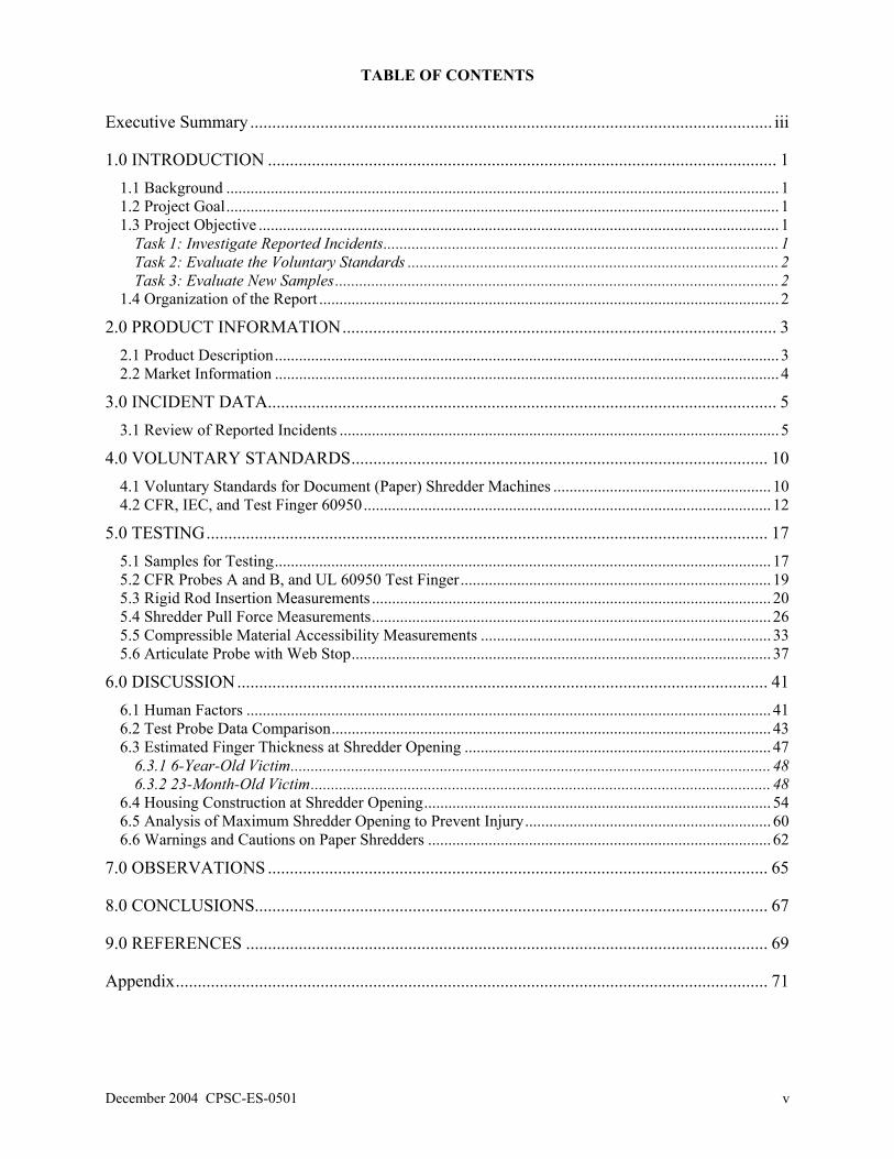
TABLE OF CONTENTS
Executive Summary ....................................................................................................................... iii
1.0 INTRODUCTION .................................................................................................................... 1 1.1 Background ......................................................................................................................................... 1 1.2 Project Goal......................................................................................................................................... 1 1.3 Project Objective ................................................................................................................................. 1
Task 1: Investigate Reported Incidents.................................................................................................. 1 Task 2: Evaluate the Voluntary Standards ............................................................................................ 2 Task 3: Evaluate New Samples.............................................................................................................. 2
1.4 Organization of the Report .................................................................................................................. 2 2.0 PRODUCT INFORMATION................................................................................................... 3
2.1 Product Description............................................................................................................................. 3 2.2 Market Information ............................................................................................................................. 4
3.0 INCIDENT DATA.................................................................................................................... 5 3.1 Review of Reported Incidents ............................................................................................................. 5
4.0 VOLUNTARY STANDARDS............................................................................................... 10 4.1 Voluntary Standards for Document (Paper) Shredder Machines ...................................................... 10 4.2 CFR, IEC, and Test Finger 60950..................................................................................................... 12
5.0 TESTING................................................................................................................................ 17 5.1 Samples for Testing........................................................................................................................... 17 5.2 CFR Probes A and B, and UL 60950 Test Finger............................................................................. 19 5.3 Rigid Rod Insertion Measurements ................................................................................................... 20 5.4 Shredder Pull Force Measurements................................................................................................... 26 5.5 Compressible Material Accessibility Measurements ........................................................................ 33 5.6 Articulate Probe with Web Stop........................................................................................................ 37
6.0 DISCUSSION......................................................................................................................... 41 6.1 Human Factors .................................................................................................................................. 41 6.2 Test Probe Data Comparison............................................................................................................. 43 6.3 Estimated Finger Thickness at Shredder Opening ............................................................................ 47
6.3.1 6-Year-Old Victim....................................................................................................................... 48 6.3.2 23-Month-Old Victim.................................................................................................................. 48
6.4 Housing Construction at Shredder Opening...................................................................................... 54 6.5 Analysis of Maximum Shredder Opening to Prevent Injury............................................................. 60 6.6 Warnings and Cautions on Paper Shredders ..................................................................................... 62
7.0 OBSERVATIONS .................................................................................................................. 65
8.0 CONCLUSIONS..................................................................................................................... 67
9.0 REFERENCES ....................................................................................................................... 69
Appendix....................................................................................................................................... 71

vi CPSC-ES-0501 December 2004
LIST OF FIGURES Figure 1. Types of Shredder Mechanisms .................................................................................................... 3 Figure 2. NEISS Database from January 2000 to December 2003............................................................... 5 Figure 3. IPII Database from January 2000 to December 2003.................................................................... 6 Figure 4. NEISS and IPII Incidents by Injury from January 2000 to December 2003 ................................. 7 Figure 5. Injury to Hand, 23-month-old........................................................................................................ 8 Figure 6. Injury to Hand, 6-year-old ............................................................................................................. 9 Figure 7. Test Finger used in UL 60950-1.................................................................................................. 11 Figure 8. Children Finger Accessibility Probes .......................................................................................... 12 Figure 9. Test Probe Comparison (to scale)................................................................................................ 15 Figure 10. Illustration of Dimensions Measured on the Paper Shredder .................................................... 18 Figure 11. Rod Force Measurement Setup.................................................................................................. 21 Figure 12. Sample F - Force Required for Rigid Rod Insertion (Four Different Probes). .......................... 22 Figure 13. Sample G - Force Required for Rigid Rod Insertion (Four Different Probes). ......................... 22 Figure 14. Sample G - Force Required for Rigid Rod Insertion (8.63 mm Probe)..................................... 23 Figure 15. Sample G - Force Required for Rigid Rod Insertion (9.44 mm Probe)..................................... 23 Figure 16. Illustration of the 12.24 mm Test Rod in Sample G.................................................................. 24 Figure 17. – Sample G - Force Required for Rigid Rod Insertion (12.24 mm Probe)................................ 24 Figure 18. Sample I with the 5.85 mm Test Rod. ....................................................................................... 25 Figure 19. Sample J with the Four Different Test Rods. ............................................................................ 26 Figure 20. Pull Force Measurement Setup.................................................................................................. 27 Figure 21. Pull Force Traces for Sample A ................................................................................................ 28 Figure 22. Pull Force Traces for Sample B................................................................................................. 28 Figure 23. Pull Force Traces for Sample C................................................................................................. 29 Figure 24. Pull Force Traces for Sample D ................................................................................................ 29 Figure 25. Pull Force Traces for Sample E................................................................................................. 30 Figure 26. Pull Force Traces for Sample F ................................................................................................. 30 Figure 27. Pull Force Traces for Sample G ................................................................................................ 31 Figure 28. Pull Force Traces for Sample H ................................................................................................ 31 Figure 29. Pull Force Traces for Sample I .................................................................................................. 32 Figure 30. Pull Force Traces for Sample J.................................................................................................. 32 Figure 31. Durometer Scales....................................................................................................................... 34 Figure 32. 40A Durometer “Compressible” Finger Polyurethane Samples................................................ 34 Figure 33. Test Setup for Compressible Probe. .......................................................................................... 35 Figure 34. Sample C, 6.5 mm “Compressible” Polyurethane Finger, 5 Sheets of Paper........................... 35 Figure 35. Articulate Probe with Web Stop................................................................................................ 37 Figure 36. Articulate Probe Setup............................................................................................................... 38 Figure 37. Sample F, Articulate Probe........................................................................................................ 39 Figure 38. Sample G, Articulate Probe ....................................................................................................... 39 Figure 39. Sample J, Articulate Probe ........................................................................................................ 40 Figure 40. Sample C, Articulate Probe ....................................................................................................... 40 Figure 41. 13- to 18-Month-Old Child Next to a Paper Shredder ............................................................. 42 Figure 42. Illustration of Estimated Finger Width at Shredder Opening. ................................................... 47 Figure 43. 6-Year-Old, 5th Pecentile Dimensions ...................................................................................... 48 Figure 44. 23-Month-Old (2-Year-Old, 5th Percentile Dimensions)........................................................... 49 Figure 45. Estimated Hand Thickness ........................................................................................................ 49 Figure 46. Illustration of Minimum Hand (wrist) Clearance ...................................................................... 50 Figure 47. Measured and Estimated Shredder Opening, Sample F ............................................................ 52 Figure 48. Estimated Force for an 8.25 mm Rigid Rod, Sample F............................................................. 52 Figure 49. Estimated and Measured Shredder Opening, Sample J ............................................................. 53 Figure 50. Estimated Force for 8.25 mm and 9.0 mm Rigid Rods, Sample J............................................. 54 Figure 51. Sample I, Shredder Opening Housing Interior .......................................................................... 55

December 2004 CPSC-ES-0501 vii
Figure 52. Illustration of Mating “Rabbet” Grooves on Housing............................................................... 55 Figure 53. Sample H, Shredder Opening Housing Interior......................................................................... 56 Figure 54. Partial Illustration of Shredder Opening.................................................................................... 57 Figure 55. Sample G, Shredder Opening Housing Interior......................................................................... 58 Figure 56. Illustration of Shredder Opening Expanding, Sample G ........................................................... 58 Figure 57. Sample J, Shredder Opening Housing Interior .......................................................................... 59 Figure 58. Sample F Shredder Opening Housing Interior .......................................................................... 60 Figure 59. Finger Probes Compression Setup............................................................................................. 61 Figure 60. Finger Probes Compressed with Force of 20 lbs. ...................................................................... 62 Figure 61. Hazard Symbols for Paper Shredders ........................................................................................ 62 Figure 62. Visibility of Hazard Symbols .................................................................................................... 63 Figure 63. Visibility of Control Functions.................................................................................................. 64
LIST OF TABLES Table 1. Test Probe Dimensions (see Figure 9) .......................................................................................... 13 Table 2. Paper Shredder Sample Specifications ......................................................................................... 18 Table 3. Measurements of Shredder Openings (see Figure 10) .................................................................. 19 Table 4. Probe Insertion into Shredders...................................................................................................... 20 Table 5. Rigid Rod Insertion....................................................................................................................... 21 Table 6. Maximum Pull Force Measured.................................................................................................... 27 Table 7. Compressible Rod Material .......................................................................................................... 33 Table 8. Simulated Compressible Finger Results ....................................................................................... 36 Table 9. Articulate Probe Results .............................................................................................................. 38 Table 10. Test Data Summary..................................................................................................................... 45 Table 11. Shredder Openings with the Six Compressible Probes............................................................... 51 Table 12. Warning and Caution Markings on Shredders ............................................................................ 63

viii CPSC-ES-0501 December 2004
No Text on This Page

December 2004 CPSC-ES-0501 1
1.0 INTRODUCTION
1.1 Background
Document shredder machines, commonly referred to as paper shredders, have been used
in the office environment for many years. Once sold and used exclusively in offices, paper shredders can now be found in consumers’ homes. Reasons for the increased use of paper shredders by consumers may be the prevention of identity theft and for use in the home office.
A paper shredder performs the same function whether the machine is used in the office or
home. However, paper shredders for the office are typically larger in size and are designed for high usage, whereas shredders for the home are typically smaller and designed for light to medium usage. In addition, paper shredders for the office are operated and accessible by adults, but paper shredders in a home may be accessible by small children. Accessibility of these products to children may present a hazard.
The U.S. Consumer Product Safety Commission (CPSC) staff is aware of injuries to
children, including finger amputations, associated with paper shredders used in consumers’ homes. As a result, in FY 2004, the CPSC staff evaluated different models of paper shredders and assessed the adequacy of the voluntary standard in addressing finger injuries to children. 1.2 Project Goal
The overall goal is to reduce the potential for hazards to consumers resulting from the use
of paper shredders.
1.3 Project Objective The objective of this project was to assess the adequacy of the appropriate voluntary
standards in addressing finger injuries to children and consider possible future recommendations to improve the safety requirements in the UL standard, if appropriate. To accomplish this objective, the evaluation was divided into three tasks:
Task 1: Investigate Reported Incidents The objective of this task was to collect and analyze information on incidents reported to
CPSC through the National Electronic Injury Surveillance System (NIESS) and the Injury and Potential Injury Incidents (IPII) data collection system.
NEISS, which is operated by the CPSC, is a special injury data collection system – the only one of its kind in the country. NEISS collects current data on a broad range of injury-related issues. It also provides national estimates on the number and severity of consumer-product-related injuries. NEISS data is collected from emergency room visits from 98 selected hospitals across the United States. The statistical sample is selected from over 6,000 hospitals with 24-hour emergency services and at least six beds.

2 CPSC-ES-0501 December 2004
The IPII data system includes consumer letters, CPSC Hotline complaints, newspaper clippings, and medical examiner reports. This information is collected and input into the CPSC database.
CPSC field investigators may follow-up on selected incidents by conducting In-Depth-
Investigations (IDIs). Reports of these IDIs may contain interviews with the victim, witnesses, and the emergency personnel responding to the incident.
Task 2: Evaluate the Voluntary Standards
The objective of this task was to evaluate the voluntary standards for paper shredders. The Underwriters Laboratories (UL) voluntary standard that applies to this product is UL 60950-1 Information Technology Equipment – Safety – Part 1: General Requirements. The international standard that applies to this product is IEC (International Electrotechnical Commission) 60950-1, Information Technology Equipment – Safety Part 1: General Requirements. If CPSC staff considers any future recommendations to improve the safety requirements in the UL standard, similar requirements may also apply to the IEC standard.
Task 3: Evaluate New Samples
The objective of this task was to evaluate sample paper shredders available from retail
stores to determine if current designs pose a potential safety hazard to people’s fingers, particularly children’s fingers. Tests were conducted on the sample shredders to determine the mechanisms by which injuries may occur. 1.4 Organization of the Report
This report is presented in nine sections: Introduction, General Information, Incident
Data, Voluntary Standards, Testing, Discussion, Observations, Conclusions, and References. Tasks 1 and 2 are contained in the Incident Data and Voluntary Standards section. Task 3 is contained in the Testing section. The Discussion section brings together all three tasks and how they may relate to each other. The Observations and Conclusions sections list the significant observations and conclusions drawn from the testing that may be useful in preventing finger injuries in the future.
The US Consumer Product Safety Commission uses metric units of measurements when
possible. In this document intended for consumer products, however, in North America certain non-metric units are so widely used instead of metric units that it is more practical and less confusing to include certain measurements values in customary units only.
December 2004 CPSC-ES-0501 3
2.0 PRODUCT INFORMATION 2.1 Product Description
Shredder designs vary according to how they are intended to be used and the types of
materials that will be destroyed. Paper shredders for home use, or personal shredders, are designed for infrequent use. Too much paper or constant use may cause these shredders to jam or breakdown. These shredders typically can handle only paper, but may also handle an infrequent paper clip or staple. Personal models can take 2-10 sheets at one pass and typically cost between $20 to $200.
Commercial grade paper shredders are much larger than those intended for home use.
Commercial shredders are designed to handle more sheets of paper and other objects, such as credit cards, videocassettes, and computer diskettes. The shredders are equipped with higher power motors that allow them to chew through paper for longer periods of time without jamming or overheating. Office models can take 20 to 50 sheets at one pass and cost over $2,000.
A medium grade shredder – a cross between personal and commercial grade shredders –
can be used in a home or for light duty in an office. Medium grade shredders offer slightly more powerful motors than personal models, but at more affordable prices than commercial grade shredders. Medium grade models may take up to 20 sheets at one pass and cost upwards of $1,000.
Paper shredders contain a cutting assembly and possibly a container to catch shredded
paper. The cutting assembly consists of a pair of rotating, intermeshing cutting blades; a paper comber; and a motor that drives this assembly. Paper is fed between the two intermeshing blades and is split into many small pieces by the force of the blades.
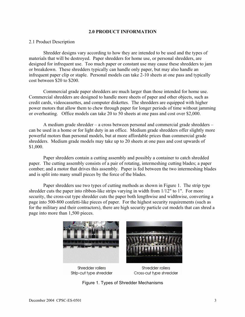
Paper shredders use two types of cutting methods as shown in Figure 1. The strip type
shredder cuts the paper into ribbon-like strips varying in width from 1/12" to 1". For more security, the cross-cut type shredder cuts the paper both lengthwise and widthwise, converting a page into 500-800 confetti-like pieces of paper. For the highest security requirements (such as for the military and their contractors), there are high security particle cut models that can shred a page into more than 1,500 pieces.
Figure 1. Types of Shredder Mechanisms

4 CPSC-ES-0501 December 2004
The shredded paper is held in one of a variety of containers. Some paper shredders for
home use are simply draped over the edges of, or straddle, a wastebasket. Slightly more expensive models may come equipped with their own wastebasket. Both of these types of paper shredders allow the paper shredder opening to be in close proximity to the floor (the height of the wastebasket). Most office grade shredders typically come with an enclosed cabinet with wheels that make it easier to roll about the office. Finally, there are some shredders that come with a stand that can hold a plastic bag.
The paper shredders used in this test program were selected by design, cost, and features
available. Different shredder design types were selected to demonstrate the variety available to consumers. The paper shredders selected were in the price range of $20 to $70, and included similar selectable settings and features.
2.2 Market Information
Approximately 20% of all households or about 22 million households, have at least 1
paper shredder.1 There were an estimated 10-20 million paper shredders sold for home and office use in 2002.2 The number of sales (home and office) is expected to increase approximately 20% per year. According to these sources, one of the reasons consumers are purchasing paper shredders for home use is to reduce the likelihood of identity theft.
A report by the Federal Trade Commission (FTC) released in 2003 reported that identity
thefts victimized 9.9 million Americans and cost businesses and consumers almost $53 billion last year. The study was conducted using telephone interviews and used a Random-Digit-Dialing (RDD) sampling methodology to obtain a random sample of U.S. adults age 18 and older. The survey yielded more than 4,000 completed interviews with a nationally representative sample. The FTC concluded that, in the past year, about 3.2 million (of the total 9.9 million victimized) people discovered identity thieves had stolen their personal information in order to open new bank or credit card accounts. Using a paper shredder to destroy personal information before tossing it into the trash has provided consumers with one way to become more proactive in preventing identity theft.
1 CNN March 23, 2004, interview with a spokesperson from Staples. 2 Source: Acclaro Growth Partners, Reston, VA, May 2004

December 2004 CPSC-ES-0501 5
3.0 INCIDENT DATA
3.1 Review of Reported Incidents
CPSC staff conducted a search of the NEISS database for incidents occurring during the
period January 1, 2000 through December 31, 2003. The search resulted in 23 reported injuries to fingers from a paper shredder mechanism. No national estimate for injuries is given because of the small sample size. The ages of the victims ranged from 14 months old to 65 years old. Figure 2 shows the ages of the victims and the number of incidents (NEISS data).
NEISS Database
from January 2000 to December 2003
0
1
2
3
4
5
6
7
8
14 m
onths
15 m
onths 2 3 4 5 12 21 33 34 43 49 65
Age (years old)
Num
ber o
f Inc
iden
ts
Figure 2. NEISS Database from January 2000 to December 2003 CPSC staff conducted an IPII data search for incidents occurring during the period
January 1, 2000 through December 31, 2003. There were eight incidents involving injuries to fingers from paper shredders.∗ The eight incidents from the IPII database involved injuries ranging from finger contusion and laceration, to amputation of the fingers. The victims’ ages ranged from 18 months to 20 years old. Figure 3 shows the ages of the victims and the number of incidents (IPII data).
∗ From the period from January 1, 1995 through December 31, 2003, the IPII database revealed four incidents in which dogs’ tongues were caught or shredded in paper shredders.

6 CPSC-ES-0501 December 2004
IPII Databasefrom January 2000 to December 2003
0
1
2
18 months 22 months 23 months 2 6 20 unknown(adult)
Age (years old)
Num
ber o
f Inc
iden
ts
Figure 3. IPII Database from January 2000 to December 2003 The NEISS and IPII database contained reports 31 incidents for the period January 1,
2000 to December 31, 2003. The incidents ranged from contusions to amputations, as shown in Figure 4. Twelve of the 31 incidents involved children 2 years old and younger. Ten of the 31 incidents involved children from 3 years old to 12 years old. Nine of the 31 incidents involved children over 12 years old to adults.
There were three incidents in which finger contusions occurred when the finger became
stuck in a paper shredder; these incidents involved an 18-month-old child, a 22-month-old child, and a 20-year-old adult. The incident involving the adult occurred when the consumer was pushing paper into the shredder and her finger became caught. For the 18-month-old and the 22-month-old, the events before the finger became stuck in the shredder opening are unknown.
Twenty-three incidents involved lacerations to the fingers. The victims ranged from a
14-month-old child to adults. An incident involving a 2-year-old child resulted in severe lacerations to his right middle and ring fingers. The child was placing a piece of paper into the paper shredder when the shredder pulled his hand into the shredder opening. An incident involving an adult worker most likely occurred at a business.
Five incidents involving partial finger amputations occurred to children as young as 23
months old to a 33-year-old adult. The incident involving the 33-year-old resulted in partial amputation of a thumb. An incident involving a 4-year-old resulted in amputation of the finger tips. Three incidents involving a 23-month-old child and two 6-year-old children resulted in amputations of three fingers in each incident.

December 2004 CPSC-ES-0501 7
NEISS and IPII Database according to inuryfrom January 2000 to December 2003
01
23
45
67
89
1011
1213
Num
ber o
f In
cide
nts
by In
jury
Amputations 1 3 1
Lacerations 9 7 7
Contusion 2 0 1
2 years old and under 3 to 12 years old over 12 years old
Figure 4. NEISS and IPII Incidents by Injury from January 2000 to December 2003 For incidents involving the 23-month-old child and one of the 6-year-old children that
resulted in amputation of three fingers, a CPSC field investigator was able to obtain interviews with the families. The In-depth Investigations (IDIs) are documented in IDI 031028CCN0080 and IDI 031015CAA3009. Summaries of these incidents are described below. Summary from IDI031028CCN0080
The incident occurred in the family’s home. The mother had been shredding junk mail for about five minutes before the incident. The mother was handing the junk mail to her two boys, a 3-1/2-year-old and a 23-month-old. The boys were taking turns putting paper in the shredder. The mother was only about two feet away from the children when the incident occurred. She had turned away for just a few seconds when she heard the 23-month-old crying. The oldest son screamed that his brother's fingers were caught in the shredder.
As the mother was trying to free her son's fingers from the shredder, she called to her 11-
year-old daughter to dial 911. The shredder was still running as the mother tried to free her son's fingers, and then the shredder suddenly stopped. She then tried to reverse the shredder so it would expel her son's fingers, but it would not reverse. She looked for a release button, but could not find one. She then unplugged the shredder and carried it, still attached to her son's

8 CPSC-ES-0501 December 2004
fingers, to the hospital. Medical personnel attempted to free the boy’s fingers from the shredder by switching it to reverse, which was unsuccessful. Eventually, the fire department was summoned and successfully freed the boy’s fingers.
The boy's left index finger to the first joint, middle finger to the second joint, and ring
finger to the second joint were amputated by the shredder, as shown in Figure 5.
Figure 5. Injury to Hand, 23-month-old
Summary from IDI 031015CAA3009 The incident occurred in a family’s home. The family of 5 (mother, father, 6-year-old
daughter, and two sons, 3 and 10 years old) had purchased a new paper shredder. The incident occurred on the same day the paper shredder was purchased.
The mother had been shredding paper and wanted the children to learn how to safely
operate the shredder. The children were taking turns learning how to operate the shredder, which was set to “auto.” The 3-year-old had finished shredding a few pieces of paper and began to move about the room. The 6-year-old girl was standing in front of the shredder getting ready to shred a piece of paper, and her 10-year-old brother was standing next to her. The father had left the room to answer the doorbell, and the mother had turned her head to get another piece of paper. At this time, the 6-year-old girl inserted a piece of paper into the shredder. She then turned her head to see what her younger brother was doing when the shredder pulled the fingers of her left hand into the cutting blades. The mother tried to pull out the girl’s hand, but the cutting blades would not release her fingers. The mother attempted to turn off the shredder, but slid the switch to the “reverse” shredding position. The mother then pulled the plug, which stopped the shredder. The girl’s left 3rd, 4th and little fingers were partially amputated by the shredder, as shown in Figure 6. (The little finger was reattached.)

December 2004 CPSC-ES-0501 9
Figure 6. Injury to Hand, 6-year-old
CPSC staff conducted an additional IDI (040427CCN0548) of an incident that occurred in a family’s home in March 2004. The mother and her 5-year-old child were at home packing to move to another house. The mother was shredding papers when her son asked if he could shred some papers too. The mother had let her son shred paper in the past without any problems so this request was not unusual. The mother was sitting next to the child when the incident occurred. The child was shredding paper when the shredder stalled. The child stuck his fingers in the shredder to push the paper through the shredder when the shredder began operating again. The child started screaming because his fingers had become stuck in the shredder. The mother turned to see her son’s fingers stuck in the shredder; she attempted to get the child’s fingers out of the shredder but couldn’t. She thought of attempting to remove the child’s fingers out of the shredder using the reverse button but feared that this may cause further damage. She called 911 for assistance. Medical personnel at the victim’s home could not get the boy’s fingers out of the shredder so the child was taken to the local children’s hospital with the shredder still attached to his hand. The medical personnel at the children’s hospital could not free the boy’s fingers. His fingers were later freed with some device that pulled apart the shredding mechanism. The incident resulted in the 4th finger (unknown which hand) getting partially amputated.
In the three IDIs summarized above, there were some similarities in the events that
occurred before, during, and after the incidents. The adults allowed the children to insert paper into the shredder. The children were inserting paper into the shredder under the supervision of an adult nearby. The incidents occurred when the children were inserting paper into the shredder. After the incident occurred, the adults present where looking for some type of releasing device and/or attempted to reverse the motor in hopes of expelling the hand and fingers. The Medical personnel had difficulty freeing the victims’ fingers. In the three IDIs, the paper shredders involved in the incidents had cross-cut type shredding mechanisms.

10 CPSC-ES-0501 December 2004
4.0 VOLUNTARY STANDARDS
4.1 Voluntary Standards for Document (Paper) Shredder Machines
There are two voluntary standards that apply to paper shredders. One is IEC 60950-1, Information technology equipment – Safety- Part 1: General requirements. The other is UL 60950-1, Safety of Information Equipment, Safety- Part 1: General Requirements. Both standards are very similar.
IEC 60950-1 and UL 60950, Section 4.4, Protection against hazardous moving parts,
subsection 4.4.1 General states:
“…moving parts which have the potential to cause injury, shall be arranged, enclosed or guarded so as to provide adequate protection against the risk of personal injury.” Subsection 4.4.2 Protection in operator access areas states:
“In an operator access area, protection shall be provided by a suitable construction reducing the likelihood of access to hazardous moving parts, or by locating the moving parts in an enclosure provided with mechanical or electrical safety interlocks that remove the hazard when access is gained.” If this requirement cannot be satisfied while allowing the equipment to function as
intended, the operator can have access to the moving parts if all of the following requirements are met:
• The moving part is integral to the function of the equipment (for example, moving
parts of a paper cutter); and • The hazard associated is obvious to the operator; and • A warning is displayed to keep fingers and other body parts away.
The word “operator” would suggest that the protection is not intended to protect against hazards to persons who should not access or use the shredder machine.
Both standards use a test finger probe to determine accessibility to moving parts. IEC
60950-1 and UL 60950-1 reference “Figure 2A – Test Finger” in the standards. The test finger is the same in both standards. The test finger is also listed in IEC 61032, Protection of persons and equipment by enclosures – Probe for verification, as Figure 2 – Test probe B. Figure 7 is an excerpt from UL 60950-1 that illustrates the test finger (probe) to be used to determine accessibility of moving parts in a paper shredder.
The standards state that: Compliance is checked by inspection and where necessary by a test with the test finger, figure 2A (see 2.1.1.1), after removal of OPERATOR-detachable parts, and with OPERATOR access doors and covers open.

December 2004 CPSC-ES-0501 11
Unless additional measures have been taken as specified above, it shall not be possible to touch hazardous moving parts with the test finger, applied without appreciable force in every possible position. Openings preventing the entry of the test finger, figure 2A (see 2.1.1.1) are further tested by means of a straight unjointed version of the test finger applied with a force of 30 N. If the unjointed finger enters, the test with the test finger, figure 2A (see 2.1.1.1) is repeated, except that the finger is pushed through the opening using any necessary force up to 30 N.
Excerpt from “Figure 2A – Test Finger”
UL 60950-1, Safety of Information Equipment – Safety – Part 1: General Requirements First Edition, dated April 1, 2003, Page 63
Figure 7. Test Finger used in UL 60950-1

12 CPSC-ES-0501 December 2004
4.2 CFR, IEC, and Test Finger 60950
In UL 60950, the test probe length is 80 mm (3.15 in), which represents the maximum length of the index finger of a 12.5- to 13.0-year-old child. The test probe diameter of 12 mm (0.47 in) represents the minimum diameter of the index finger of an 11.5- to 12.5-year-old child (Snyder et. al, 1977). The probe appears to represent a worst-case index finger for approximately a 12-year-old child.
The Code of Federal Regulations (CFR), 16 C.F.R. §1500.48, and IEC contain
dimensions for children’s finger probes to test accessibility in other products. There are two sizes of children’s finger probes in the CFR and in IEC 61032. In the Code of Federal Regulations, 16 C.F.R. §1500.48, Figure 2 illustrates two sizes for children’s finger probes. One size represents children from 0-36 months old and the other size represents children from 37-96 months old, as shown in Figure 8. In the IEC, one size represents children from 0-36 months old, and the other size represents children from 37-168 months old. The dimensions for the IEC children’s probes and the CFR children’s probe are the same.
In Figure 8, Probe A for 0-36 months old will be referred to as the CFR Probe A, and
Probe B for 37-96 months old will be referred to as CFR Probe B in this document. The smallest children’s finger probe (CFR Probe A) represents the worst case for a 5th percentile 0- to 36-month-old child. The probe finger length of 41 mm (1.6 in) represents the middle finger length for a 5th percentile 37- to 42-month-old (Snyder et al, 1975). The test probe diameter of 5.6 mm (0.2 in) represents the minimum index finger diameter for a 0- to 3-month-old child (Snyder et al, 1975).
Excerpt from “Figure 2 – Accessibility Probes” of 16 C.F.R. §1500.48
Figure 8. Children Finger Accessibility Probes

December 2004 CPSC-ES-0501 13
Figure 9 below compares the finger probes in UL 60950/IEC Probe B and the children’s
finger probes in the CFR and IEC. Table 1 lists the dimensions of each finger section and diameter that are labeled in Figure 9.
Table 1. Test Probe Dimensions (see Figure 9)
Test Probe a
mm (in)
b mm (in)
c mm (in)
d mm (in)
a+b+c mm (in)
CFR Probe A, IEC Probe 19 14.7 (0.57)
14.7 (0.57)
14.7 (0.57)
5.6 (0.22)
44.1 (1.73)
CFR Probe B, IEC Probe 18 19.3 (0.76)
19.3 (0.76)
19.3 (0.76)
8.6 (0.34)
57.9 (2.28)
UL 60950, IEC 60950 30 (1.18)
30 (1.18)
20 (0.78)
12 (0.47)
80 (3.15)
As discussed in Section 3.1 Review of Reported Incidents, more than half of the incidents
associated with paper shredders involved children under 5 years old, and more than half of those involved children between the ages of 14 months and 2 years. The estimated∗ index finger diameter of the 5th percentile 13 to 18 month olds is 7.8 mm (0.31 in). The 5th percentile index finger diameter for the youngest group at risk is smaller than the test finger used in UL 60950.
∗ The method for estimating index finger length and diameter for a 13- to 18-month-old child is in Section 6.0 Discussion.

14 CPSC-ES-0501 December 2004
No Text on This Page

December 2004 CPSC-ES-0501 15
CFR Probe A CFR Probe B UL 60950 and IEC 60950 IEC Probe 19 IEC Probe 18 Figure 2A Test Finger
Figure 9. Test Probe Comparison (to scale)

16 CPSC-ES-0501 December 2004
No Text on This Page

December 2004 CPSC-ES-0501 17
5.0 TESTING
Samples of paper shredders were purchased from retail stores for testing. All the paper
shredder samples were listed to UL 60950. Testing was conducted to better understand the differences in characteristics among shredder designs and to collect information to help determine how finger injuries may be occurring, particularly to children. Testing was conducted in six phases:
1. Record the characteristics of the paper shredder samples collected. 2. Test each shredder opening with the CFR children’s finger probes (A and B) and the
test finger from UL 60950. 3. Determine the amount of force required to insert different sized rigid probes into the
shredder opening. 4. Determine the pull force of the paper shredder when one, three, or five sheets of
paper are fed into the shredder. 5. Determine if the pull force can draw in a simulated test finger that was not
constructed of rigid material while a sheet of paper is being drawn into the paper shredder.
6. Test each shredder opening with the Articulate Probe. 5.1 Samples for Testing
Table 2 lists the ten paper shredders that were collected along with their specifications. All the samples were designed with either a strip-cut or cross-cut shredding mechanism. The throat size ranged from 8 ¾ or 9 ½ inches; the maximum number of sheets per pass ranged from 5 to 10; and all the samples had auto on/off and reverse functions. Six samples had a separate off switch that removed power from the unit.
All the paper shredder samples tested included a wastebasket. The shredder mechanism
was placed on top of the wastebasket and the distance from the floor to the top of the shredder was measured. The height of the top of the shredder to the floor ranged from 33 cm (13 in) to 42 cm (16.5 in).
Dimensions were measured at the shredders’ openings and where the shredded paper
exits the shredding mechanism, as shown in Figure 10. The distances from the throat opening to the shredder rollers (CC) and the throat gap (AA) were measured. Table 3 lists the measurements for the paper shredder samples.
The estimated 95th percentile index finger length∗, 45 mm (1.77 in), of a 13- to 18-month-
old can reach the shredder rollers in all the paper shredder samples (measurement CC). However, the estimated 5th percentile index finger diameter, 7.8 mm (0.31 in) of the same age child is too large to fit the widest opening of the paper shredder samples (measurement AA).
∗ The method for estimating index finger length and diameter for a 13- to 18-month-old child is in the Discussion section.

18 CPSC-ES-0501 December 2004
Table 2. Paper Shredder Sample Specifications
Sample Throat Size
Maxi. # of Sheets in a single pass Shred Type Rate1 Functions2
A 9” 5 (20 lb. weight) Strip-cut 3 sec/sheet 1,2,3
B 8 ¾” 5 Strip-cut 18 ft/min 1,3,4
C 9” 6 Strip-cut 12 ft/min 1,2,3
D 8 ¾” 5-6 (20 lb. weight) Strip-cut 10 ft/min 1,2,3
E 9” 7 Strip-cut Unknown 1,2,3,4
F5, 6 8 ¾” 10 Cross-cut Unknown 1,3,4
G3, 5, 6 9” 7 Cross-cut Unknown 1,3,4
H5, 6 9” 8 Cross-cut 10 ft/min 1,2,3
I4, 5, 6 9 ½” 5 Cross-cut Unknown 1,3,4
J4,5 8 ¾” 5 Cross-cut Unknown 1,3,4 1 As specified in the instruction manual or product literature 2 Functions
1 - Auto On/Off Switch 2 - Forward 3 - Reverse 4 - Off Switch
3 The unit contains a removable input tray 4 This unit does not have a swinging cover on the lower opening of the paper shredder. 5 These units contain a safety switch. The unit is disabled when the shredder unit is removed from the wastebasket. 6 These units also contain a swinging cover on the lower opening of the paper shredder.
Figure 10. Illustration of Dimensions Measured on the Paper Shredder

December 2004 CPSC-ES-0501 19
Table 3. Measurements of Shredder Openings (see Figure 10)
Sample AA mm (in)
BB mm (in)
CC mm (in)
DD mm (in)
EE mm (in)
FF mm (in)
GG mm (in)
HH mm (in)
A 3.3 (0.13)
18.5 (0.73)
2.1 (0.08)
10 (0.39)
5.4 (0.21)
19.1 (0.75)
12.5 (0.49)
17.0 (0.67)
B 3.8 (0.15)
37.2 (1.46)
31.6 (1.24)
9.9 (0.39)
3.8 (0.15)
22.4 (0.88)
7.6 (0.30)
9.4 (0.37)
C 3.7 (0.14)
20.2 (0.80)
9.1 (0.36)
26.5 (1.04)
5.7 (0.22)
18.3 (0.72)
5.18 (0.20)
17.5 (0.69)
D 3.7 (0.14)
27.1 (1.07)
14.9 (0.59)
38.7 (1.52)
5.8 (0.23)
22.4 (0.88)
12.8 (0.50)
21.1 (0.83)
E 3.8 (0.15)
33.5 (1.32)
18.8 (0.74)
39.0 (1.54)
5.2 (0.20)
20.6 (0.81)
14.4 (0.57)
16.1 (0.63)
F5, 6 5.4 (0.21)
45.2 (1.78)
24.1 (0.95)
113.3 (4.46)
93.5 (3.68)
93.5 (3.68)
34.9 (1.37)
34.9 (1.37)
G3, 5, 6 4.3 (0.17)
58.3 (2.30)
32.8 (1.29)
95.6 (3.76)
45.6 (1.80)
36.4 (1.43)
31.8 (1.25)
55.5 (2.19)
H5, 6 4.9 (0.19)
37.0 (1.46)
23.9 (0.94)
9.7 (0.38)
55.2 (2.17)
55.2 (2.17)
36.6 (1.44)
36.6 (1.44)
I4, 5, 6 4.4 (0.17)
43.8 (1.72)
10.9 (0.43)
17.1 (0.67)
45.6 (1.80)
31.3 (1.23)
25.4 (1.00)
50.9 (2.00)
J4,5 2.9 (0.11)
33.0 (1.30)
22.5 (0.89)
57.6 (2.27)
64.6 (2.54)
32.2 (1.27)
32.2 (1.27)
64.6 (2.54)
3 The unit contains a removable input tray 4 This unit does not have a swinging cover on the lower opening of the paper shredder. 5 These units contain a safety switch. The unit is disabled when the shredder unit is removed from the wastebasket. 6 These units also contain a swinging cover on the lower opening of the paper shredder.
5.2 CFR Probes A and B, and UL 60950 Test Finger The child’s finger probes, as specified in IEC 61032 figures 12 and 13 and in 16 C.F.R.
§1500.48, figure 2, were used to determine accessibility to moving parts in the paper shredder samples. The UL 60950 test finger probe was also used to determine accessibility to moving parts through shredder openings.
According to UL 60950, the test finger as specified in figure 2A is to be tested with a
force of 30 N. The same force, 30 N (6.75 lbs.), was applied using the child finger probes. If a probe did not pass the shredder opening with less than 6.75 lbs. of force, the next larger probe was not tested, assuming that it also would not have passed the shredder opening. The smallest probe (CFR Probe A) was able to pass the shredder opening for samples F,G and J, using less than 6.75 lbs. of force. A maximum force of only 3.1 lbs. was required to pass the shredder opening and contact the shredder mechanism for sample F. The second probe (CFR Probe B) was able to pass the shredder opening for only sample F, which required 6.4 lbs. of force. Only sample F required testing of the UL 60950 test finger. The largest probe (UL 60950 test finger)

20 CPSC-ES-0501 December 2004
could not be inserted past the shredder opening when a maximum force of 6.75 lbs. was applied, as expected. The shredders were not tested with the UL 60950 test finger because the next smaller test probe (CFR Probe B) could not pass the shredder opening using a maximum force of 6.75 lbs.
Table 4. Probe Insertion into Shredders
CFR Probe A CFR Probe B UL 60950 Test Finger
Sample Contact Shredder
Mechanism
Maximum Force (lbs.)
Contact Shredder
Mechanism
Maximum Force (lbs.)
Contact Shredder
Mechanism
Maximum Force (lbs.)
A No 6.8 NT N/A NT N/A
B No 6.8 NT N/A NT N/A
C No 6.8 NT N/A NT N/A
D No 6.8 NT N/A NT N/A
E No 6.8 NT N/A NT N/A
F Yes 3.1 Yes 6.4 No 6.8
G Yes 3.3 No 6.8 NT N/A
H No 6.8 NT N/A NT N/A
I No 6.8 NT N/A NT N/A
J Yes 4.8 No 6.8 NT N/A Yes The probe fit through the shredder opening and/or contacted the shredder rollers. No The probe did not fit through the shredder opening with the force applied. NT No Test
5.3 Rigid Rod Insertion Measurements
The nominal physical strength required for a child to insert a finger into the opening of a paper shredder is unknown, but the force required to insert various diameter probes may be helpful in determining how injuries to children’s fingers can occur.
A series of tests was conducted to determine the force required to push a steel rod into a
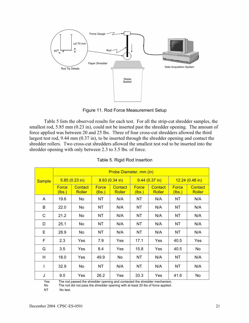
shredder opening and possibly contact the shredder rollers. Four rod diameters were used; the diameters were similar to those of the CFR probes and the IEC/UL 60950 test fingers. The diameters of the rods used were 5.85 mm (0.23 in), 8.63 mm (0.34 in), 9.44 mm (0.37 in), and 12.24 mm (0.48 in). The tips of the rods had a slight 45° chamfer on the edge, as shown in Figure 11. During the tests, each test rod was attached to a force gauge. The rod/force gauge assembly was inserted into the shredder opening until the rod contacted the shredder roller or until a minimum force of about 20 lbs. was applied. The force gauge data was recorded by a data acquisition system that sampled at 10 Hz, or 10 samples per second.
December 2004 CPSC-ES-0501 21
Figure 11. Rod Force Measurement Setup Table 5 lists the observed results for each test. For all the strip-cut shredder samples, the
smallest rod, 5.85 mm (0.23 in), could not be inserted past the shredder opening. The amount of force applied was between 20 and 25 lbs. Three of four cross-cut shredders allowed the third largest test rod, 9.44 mm (0.37 in), to be inserted through the shredder opening and contact the shredder rollers. Two cross-cut shredders allowed the smallest test rod to be inserted into the shredder opening with only between 2.3 to 3.5 lbs. of force.
Table 5. Rigid Rod Insertion
Probe Diameter, mm (in)
5.85 (0.23 in) 8.63 (0.34 in) 9.44 (0.37 in) 12.24 (0.48 in) Sample Force (lbs.)
Contact Roller
Force (lbs.)
Contact Roller
Force (lbs.)
Contact Roller
Force (lbs.)
Contact Roller
A 19.6 No NT N/A NT N/A NT N/A
B 22.0 No NT N/A NT N/A NT N/A
C 21.2 No NT N/A NT N/A NT N/A
D 25.1 No NT N/A NT N/A NT N/A
E 28.9 No NT N/A NT N/A NT N/A
F 2.3 Yes 7.9 Yes 17.1 Yes 40.5 Yes
G 3.5 Yes 8.4 Yes 15.8 Yes 40.5 No
H 18.0 Yes 49.9 No NT N/A NT N/A
I 32.9 No NT N/A NT N/A NT N/A
J 9.0 Yes 26.2 Yes 33.3 Yes 41.6 No Yes The rod passed the shredder opening and contacted the shredder mechanism. No The rod did not pass the shredder opening with at least 20 lbs of force applied. NT No test.

22 CPSC-ES-0501 December 2004
Sample F required only 2.3 lbs of force to insert the smallest rod, 5.85 mm (0.23 in), and
it required 40.5 lbs. to insert the largest rod, 12.24 mm (0.48 in). Sample G required only 3.5 lbs of force to insert the smallest rod, 5.85 mm (0.23 in). The largest rod, 12.24 mm 0.48 in), could be only partially inserted past the shredder opening, and it did not contact the shredder rollers. For sample G, the 9.44 mm (0.37 in) rod required 15.8 lbs. of force to insert it past the shredder opening and contact the shredder rollers. Figures 12 and 13 show the test results for samples F and G, respectively .
Sample FCross Cut Document Shredder
0
5
10
15
20
25
30
35
40
45
0
0.99
1.98
2.97
4.01 5
6.04
6.98
8.02
9.01 10 11
Time (seconds)
Forc
e (lb
s.) Probe 5.85 mm
Probe 8.63 mmProbe 9.44 mmProbe 12.24 mm
Figure 12. Sample F - Force Required for Rigid Rod Insertion (Four Different Probes).
Sample GCross Cut Document Shredder
0
5
10
15
20
25
30
35
40
45
00.
991.
922.
913.
954.
945.
936.
977.
968.
959.
94 11 1212
.9 14 15 16 17
Time (seconds)
Forc
e (lb
s.) Probe 5.85 mm
Probe 8.63 mmProbe 9.44 mmProbe 12.24 mm
Figure 13. Sample G - Force Required for Rigid Rod Insertion (Four Different Probes).

December 2004 CPSC-ES-0501 23
Sample G contains a removable tray at the paper input throat. The tray slides into four dovetail grooves at the paper shredder opening. During testing, the rigid test rods would cause the removeable tray to slide upward or pop off the paper shredder. Also, the upper portion of the shredder housing opening would deflect, and the test rod would catch on a lower portion of the shredder opening housing. Figures 14 and 15 show three distinctive peaks when the 8.63 mm (0.34 in) and 9.44 mm (0.37 in) test rods passed each section of the shredder opening, respectively. The first peak was the test rod pushing past the removeable tray. The second peak was the deflection of the upper portion of the housing. The third peak was the deflection of the lower portion of the housing.
Sample GCross Cut Document Shredder
0
1
2
3
4
5
6
7
8
9
00.
99
1.92
2.91
3.95
4.94
5.93
6.97
7.96
8.95
9.94 11 12
12.9 14 15 16 17
Time (seconds)
Forc
e (lb
s.)
Probe 8.63 mm
Removable Tray
First Edge Second Edge
Figure 14. Sample G - Force Required for Rigid Rod Insertion (8.63 mm Probe).
Sample GCross Cut Document Shredder
0
2
4
6
8
10
12
14
16
18
00.
991.
922.
913.
954.
945.
936.
977.
968.
959.
94 11 1212
.9 14 15 16 17
Time (seconds)
Forc
e (lb
s.)
Probe 9.44 mmRemovable Tray
First EdgeSecond Edge
Figure 15. Sample G - Force Required for Rigid Rod Insertion (9.44 mm Probe).

24 CPSC-ES-0501 December 2004
When the 12.24 mm (0.48 in) rod was tested on shredder sample G, the test rod passed
the removable tray and the upper portion of the housing but caught on the lower portion of the housing, as illustrated in Figure 16. As the rod was being pushed into the shredder opening, the removable tray would slide upward, as illustrated in Figure 16(b). The upper portion of the housing would then deflect, as illustrated in Figure 16(c). Up to 40 lbs. of force was applied, but the rod would not pass the lower portion of the housing, as shown in Figure 17. It is possible that if the rod had been more tapered or if it had a rounded tip, the rod may have been able to pass the lower portion of the housing, or it may have required less applied force.
(a) (b) (c)
Figure 16. Illustration of the 12.24 mm Test Rod in Sample G.
Sample GCross Cut Document Shredder
0
5
10
15
20
25
30
35
40
45
00.
991.
922.
913.
954.
945.
936.
977.
968.
959.
94 11 1212
.9 14 15 16 17
Time (seconds)
Forc
e (lb
s.)
Probe 12.24 mm
Removable Tray
First Edge
Second Edge
Figure 17. – Sample G - Force Required for Rigid Rod Insertion (12.24 mm Probe). The only cross-cut shredder that did not allow any of the test rods to pass the shredder
opening was sample I. Approximately 32 lbs. of force was applied with the smallest rod, 5.85 mm (0.23 in), but it would not penetrate past the shredder opening, as shown in Figure 18. An

December 2004 CPSC-ES-0501 25
explanation of the possible reasons why some rods could pass through the openings of some shredders and not others is presented in Section 6.0 Discussion.
Sample ICross Cut Document Shredder
0
5
10
15
20
25
30
35
0
1.92
3.68
5.55
7.36
9.12
10.9
3
12.7
4
14.5
16.3
1
Time (seconds)
Forc
e (lb
s.)
Probe 5.85 mm
Figure 18. Sample I with the 5.85 mm Test Rod. Similar to sample G, sample J allowed only the three smallest rods to pass the shredder
opening and contact the shredder mechanism. However, the forces required to insert the rods were greater for sample J than for sample G, as shown in Figure 19. Sample J required 9.0 lbs., 26.2 lbs., and 33.3 lbs. of force for 5.85 mm (0.23 in), 8.63 mm (0.34 in), and 9.44 mm (0.37 in) rods, respectively. For the 5.85 mm (0.23 in) and 8.63 mm (0.34 in) rods, the forces were approximately 3 times greater than those measured for sample G. For the 9.44 mm (0.37 in) rod, the force was more than twice the measured force for sample G. Similar to sample G, the largest rod, 12.24 mm (0.48 in), did not contact the shredder mechanism with approximately 40 lbs. of force.

26 CPSC-ES-0501 December 2004
Sample JCross Cut Document Shredder
0
5
10
15
20
25
30
35
40
45
00.
991.
973.
024.
065.
056.
157.
088.
139.
0610
.111
.112
.113
.114
.115
.116
.217
.218
.2
Time (seconds)
Forc
e (lb
s.) Probe 5.85 mm
Probe 8.63 mmProbe 9.44 mmProbe 12.24 mm
Figure 19. Sample J with the Four Different Test Rods.
5.4 Shredder Pull Force Measurements The objective of this series of tests was to determine the pull force of the paper shredder
when one, three, or five sheets of paper were fed into the shredder. To measure the pull force on the paper, a load cell (tension gauge) was fixed above the paper shredder sample, as shown in Figure 20. One, three, or five sheets of 20 lb. weight paper were attached to the load cell with a wide clamp. The output of the force gauge was fed into a data acquisition system that sampled at 10 Hz, or 10 samples per second.
Table 6 lists the maximum pull forces measured for each test. The cross-cut shredders
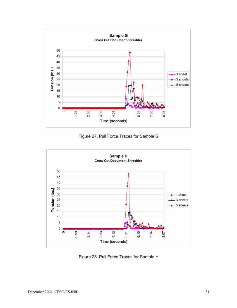
had a significantly higher pull force than the strip-cut shredders. For a single sheet of paper, a strip-cut shredder pull force measured between 1 to 2 lbs., whereas a cross-cut shredder pull force measured between 5 to 9 lbs. For three sheets of paper, a strip-cut shredder pull force measured between 5 to 11 lbs., whereas a cross-cut shredder pull force measured between 14 to 30 lbs. For five sheets of paper, a strip-cut shredder pull force measured between 15 to 22 lbs., whereas a cross-cut shredder pull force measured between around 31 and 49 lbs. Figures 21 to 30 show the traces for each of the shredder samples tested.

December 2004 CPSC-ES-0501 27
Figure 20. Pull Force Measurement Setup
Table 6. Maximum Pull Force Measured
Maximum Pull Force Measured (lbs) Sample Shredder
Type 1 sheet 3 sheets 5 sheets
A Strip-cut 1.35 11.09 14.71
B Strip-cut 2.02 6.98 16.78
C Strip-cut 1.27 4.83 21.74
D Strip-cut 1.57 10.00 21.86
E Strip-cut 2.24 7.14 17.98
F Cross-cut 8.66 29.26 48.33
G Cross-cut 8.25 19.66 48.93
H Cross-cut 5.29 13.83 48.01
I Cross-cut 6.43 18.45 36.15
J Cross-cut 7.49 18.30 31.32

28 CPSC-ES-0501 December 2004
Sample AStrip Cut Document Shredder
0
2
4
6
8
10
12
14
16
0.00
0.99
1.98
3.02
4.06
5.05
6.04
7.03
8.02
9.01
10.0
0
11.0
9
11.9
7
12.9
6
14.0
6
15.0
5
Time (seconds)
Tens
ion
(lbs.
)
1 sheet3 sheets5 sheets
Figure 21. Pull Force Traces for Sample A
Sample BStrip Cut Document Shredder
0
2
4
6
8
10
12
14
16
18
0.00
1.04
1.98
3.02
4.01
5.00
6.04
7.03
8.02
9.01
9.99
10.9
8
12.0
3
13.0
2
14.0
0
14.9
9
Time (seconds)
Tens
ion
(lbs.
)
1 sheet3 sheets5 sheets
Figure 22. Pull Force Traces for Sample B

December 2004 CPSC-ES-0501 29
Sample CStrip Cut Document Shredder
02468
1012141618202224
0
1.1
2.19
3.13
4.17
5.05
6.09
7.14
8.13
9.12
10.1
11.1
12.1
13.1
14.1
15.1
Time (seconds)
Tens
ion
(lbs.
)
1 sheet3 sheets5 sheets
Figure 23. Pull Force Traces for Sample C
Sample DStrip Cut Document Shredder
02468
1012141618202224
0
1.1
2.03
2.97
4.01
5.11 6.
1
7.14
8.13
9.12
10.1
11.1
12.1
13.1
14.1
15.1
Time (seconds)
Tens
ion
(lbs.
)
1 sheet3 sheets5 sheets
Figure 24. Pull Force Traces for Sample D

30 CPSC-ES-0501 December 2004
Sample EStrip Cut Document Shredder
0
2
4
6
8
10
12
14
16
18
20
1 11 21 31 41 51 61 71 81 91 101
111
121
131
141
151
Time (seconds)
Tens
ion
(lbs.
)
1 sheet3 sheets5 sheets
Figure 25. Pull Force Traces for Sample E
Sample FCross Cut Document Shredder
05
1015
2025
3035
4045
50
0
1.05
1.98
3.02
4.01 5
6.1
6.98
7.97
Time (seconds)
Tens
ion
(lbs.
)
1 sheet3 sheets5 sheets
Figure 26. Pull Force Traces for Sample F
December 2004 CPSC-ES-0501 31
Sample GCross Cut Document Shredder
0
5
10
15
20
25
30
35
40
45
50
0
1.04
2.03
3.02
4.01 5
6.04
7.03
8.07
Time (seconds)
Tens
ion
(lbs.
)
1 sheet3 sheets5 sheets
Figure 27. Pull Force Traces for Sample G
Sample HCross Cut Document Shredder
0
5
10
15
20
25
30
35
40
45
50
0
0.99
2.14
3.13
4.12
5.11
6.15
7.14
8.07
Time (seconds)
Tens
ion
(lbs.
)
1 sheet3 sheets5 sheets
Figure 28. Pull Force Traces for Sample H

32 CPSC-ES-0501 December 2004
Sample ICross Cut Document Shredder
0
5
10
15
20
25
30
35
40
45
50
0
0.99
1.98
2.97
3.95
4.94
5.99
6.98
7.96
Time (seconds)
Tens
ion
(lbs.
)
1 sheet3 sheets5 sheets
Figure 29. Pull Force Traces for Sample I
Sample JCross Cut Document Shredder
0
5
10
15
20
25
30
35
40
45
50
0
1.15
2.36 3.4
4.34
5.32
6.31 7.3
8.35
Time (seconds)
Tens
ion
(lbs.
)
1 sheet3 sheets5 sheets
Figure 30. Pull Force Traces for Sample J

December 2004 CPSC-ES-0501 33
5.5 Compressible Material Accessibility Measurements
One hypothetical scenario on how finger injuries may be occurring is that the child’s
fingers are being accidentally pulled into the shredder by the paper. The events that led to the incidents as summarized in both IDIs may suggest that the children’s fingers were pulled into the shredders. As the children were feeding paper into the shredder, they did not release the paper before their fingers became stuck in the shredder opening. As the paper shredder continued to pull the paper into the shredder opening, it also pulled in the children’s fingers.
A fourth series of tests was conducted using compressible rods to determine if the rods
could be drawn into the shredders as paper was fed into them. Three rods of various diameters were selected. The rod diameters were similar to the diameters of the CFR and UL 60950 test fingers. Also, two types of materials, each of a different hardness, were used for the test rods. Table 7 lists the characteristics of the rods used in the testing. The diameters of the rods were measured in three different places and averaged.
Table 7. Compressible Rod Material
Sample Material
Average Diameter mm (in)
Material Durometer*
(Tolerance ± 5) Tensile
Strength* Elongation*
6.8 (0.27)
Polyurethane 40A 850 psi No Data
9.5 (0.37)
Polyurethane 40A 850 psi No Data A
13.0 (0.51)
Polyurethane 40A 850 psi No Data
6.4 (0.25)
Buna-N (nitrile) 50A 1200 psi 500%
9.4 (0.37)
Buna-N (nitrile) 50A 1200 psi 500% B
12.6 (0.50)
Buna-N (nitrile) 50A 1200 psi 500%
*Specifications from the supplier ASTM F1578, Standard Practice for Contact Closure Cycling of a Membrane Switch,
requires the use of a rubber test finger with a hardness of 45A durometer to evaluate membrane switches. The test finger or probe is used to repeatedly contact the switch for a specified duty cycle. Durometer is the international standard for measuring the hardness of rubber, foam rubber, plastic, and most nonmetallic materials. Foam rubbers are usually measured on the Shore OO scale; solid rubbers on the Shore A scale. One object may fall within more than one scale as shown in Figure 31. Normally durometer hardness is referred to in increments of five or ten. This practice is based on (1) the fact that durometer is generally called out in specifications with a tolerance of ± 5; (2) the inherent variance from batch to batch of a given rubber compound due to slight differences in raw materials and processing techniques; and (3) the variance

34 CPSC-ES-0501 December 2004
encountered in reading durometers. For these tests, the two material hardnesses used were 40A and 50A durometers. Materials with these hardnesses were readily available.
(www.McMaster.com. McMaster ® and McMaster-Carr ® are registered trademarks of McMaster Carr Supply Company)
Figure 31. Durometer Scales Before testing, the tips of each rod were tapered to 60°, as shown in Figure 32. The taper
angle is similar to that used for the UL Accessibility Probe (as illustrated in Figure 35).
6.8 mm9.5 mm13.0 mm
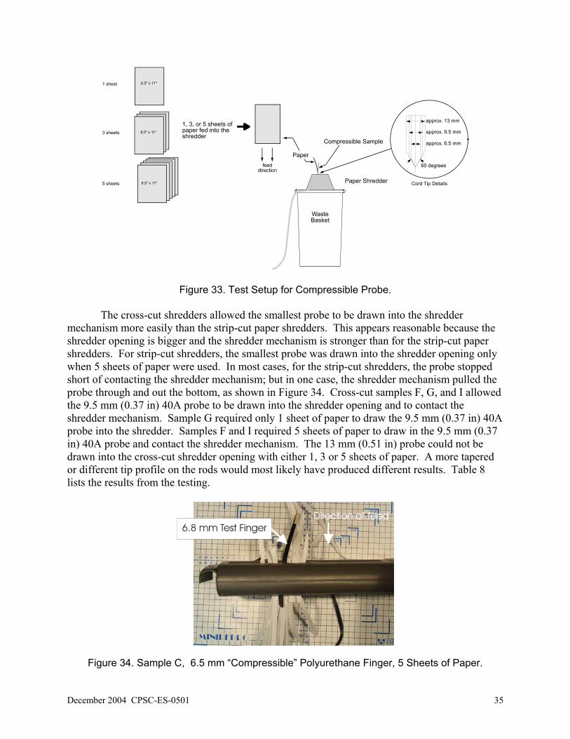
Figure 32. 40A Durometer “Compressible” Finger Polyurethane Samples. For each test, one, three, or five sheets of 8.5” x 11” paper (20 lb. weight) was used. The
paper(s) was inserted into the paper shredder, as shown in Figure 33. After approximately 1 to 2 inches of the paper had been drawn into the shredder, the rod sample was placed at the shredder opening. The rod samples were not attached to the paper to simulate gripping, but rather placed against the paper as it was being drawn into the shredder.
December 2004 CPSC-ES-0501 35
Figure 33. Test Setup for Compressible Probe. The cross-cut shredders allowed the smallest probe to be drawn into the shredder
mechanism more easily than the strip-cut paper shredders. This appears reasonable because the shredder opening is bigger and the shredder mechanism is stronger than for the strip-cut paper shredders. For strip-cut shredders, the smallest probe was drawn into the shredder opening only when 5 sheets of paper were used. In most cases, for the strip-cut shredders, the probe stopped short of contacting the shredder mechanism; but in one case, the shredder mechanism pulled the probe through and out the bottom, as shown in Figure 34. Cross-cut samples F, G, and I allowed the 9.5 mm (0.37 in) 40A probe to be drawn into the shredder opening and to contact the shredder mechanism. Sample G required only 1 sheet of paper to draw the 9.5 mm (0.37 in) 40A probe into the shredder. Samples F and I required 5 sheets of paper to draw in the 9.5 mm (0.37 in) 40A probe and contact the shredder mechanism. The 13 mm (0.51 in) probe could not be drawn into the cross-cut shredder opening with either 1, 3 or 5 sheets of paper. A more tapered or different tip profile on the rods would most likely have produced different results. Table 8 lists the results from the testing.
6.8 mm Test Finger
Figure 34. Sample C, 6.5 mm “Compressible” Polyurethane Finger, 5 Sheets of Paper.

36 CPSC-ES-0501 December 2004
Table 8. Simulated Compressible Finger Results
Smallest Probes Medium Probes Largest Probes
Rod Size → Approx. 6 mm (0.23 in) Approx. 9 mm (0.35 in) Approx. 13 mm (0.51 in)
#r of Sheets → 1 3 5 1 3 5 1 3 5
Sample Rod Material
40 No No No NT NT NT NT NT NT A
50 No No No NT NT NT NT NT NT
40 No No Yes1 No No No NT NT NT B
50 No No No NT NT NT NT NT NT
40 No No Yes2 No No No NT NT NT C
50 No No No NT NT NT NT NT NT
40 No No Yes1 No No No NT NT NT D
50 No No No NT NT NT NT NT NT
40 No No No NT NT NT NT NT NT E
50 No No Yes1 No No No NT NT NT
40 Yes2 NT NT No Yes1 Yes2 No No No F
50 Yes2 NT NT No No No No No No
40 Yes2 NT NT Yes2 NT NT No No No G
50 Yes2 NT NT No No No NT NT NT
40 Yes1 Yes2 No No No No NT NT NT H
50 Yes2 NT NT No No No NT NT NT
40 Yes1 Yes2 NT No No Yes2 No No No I
50 No Yes2 NT No No No NT NT NT
40 Yes1 Yes2 NT No No No NT NT NT J
50 Yes2 NT NT No No No NT NT NT
Yes1 Pulled the rod into the shredder opening but stopped short of contacting the shredder mechanism. Yes2 The rod contacted the shredder mechanism, and there was evidence of damage to the test rod. No The rod was not pulled into the shredder opening. Very little pull force was required to remove it from the
shredder opening. NT No test.

December 2004 CPSC-ES-0501 37
5.6 Articulate Probe with Web Stop The articulate probe with web stop is used throughout different UL standards to evaluate
accessibility to hazardous parts. In UL 60335-1 Safety of Household and Similar Electrical Appliances, Part 1: General Requirements, the standard uses the probe to evaluate accessibility to live electrical part. The articulate probe, as shown in Figure 35, represents a wide age group – both children and adults. The probe was used to evaluate accessibility of the shredder mechanism for the ten paper shredder samples. For testing of the shredder samples, a force gauge was placed behind the test probe, as shown in Figure 36. The test probe/force gauge assembly was inserted into the shredder opening until the articulate probe contacted the shredder roller or until a minimum force (8 lbs. for strip-cut shredders or 20 lbs. for cross-cut shredders) was applied. The minimum forces applied were the average pull forces measured for the strip-cut shredders and the cross-cut shredders when 3 sheets of paper were fed into the shredder openings. The articulate probe used in the testing was jointed. The force gauge data was recorded by a data acquisition system that sampled at 10 Hz, or 10 samples per second. Table 9 lists the test results.
Excerpt from “Figure 1DV – Articulate Probe with Web Stop”
UL 60335-1, Safety of Household and Similar Electrical Appliances, Part 1: General Requirements Third Edition, dated January 14, 2002, Page 117
Figure 35. Articulate Probe with Web Stop

38 CPSC-ES-0501 December 2004
Figure 36. Articulate Probe Setup
Table 9. Articulate Probe Results
Sample
Shredder opening, AA
mm (in)
Distance to shredder mech., BB
mm (in)
Max. Applied Force (lbs.)
Contacted Shredder Rollers
Estimated Distance from Probe Tip to Shredder Rollers*
mm (in)
A 3.3 (0.13)
18.5 (0.73)
12.61 No (18.5-14.3) = 4.2 (0.16)
B 3.8 (0.15)
37.2 (1.46)
8.9 No (37.2-10.4) = 26.8 (1.06)
C 3.7 (0.14)
20.2 (0.80)
7.21 Yes N/A
D 3.7 (0.14)
27.1 (1.07)
8.08 No (27.1-16.3) = 10.8 (0.43)
E 3.8 (0.15)
33.5 (1.32)
9.63 No (33.5-15.3) = 18.2 (0.72)
F 5.4 (0.21)
45.2 (1.78)
8.04 Yes N/A
G 4.3 (0.17)
58.3 (2.30)
6.23 Yes N/A
H 4.9 (0.19)
37.0 (1.46)
24.04 No (37.0-32.8) = 4.2 (0.17)
I 4.4 (0.17)
43.8 (1.72)
21.29 No (43.8-30.0) = 13.8 (0.54)
J 2.9 (0.11)
33.0 (1.30)
6.43 Yes N/A
Yes The probe passed the shredder opening and contacted the shredder mechanism with minimum force of 8 lbs.
(strip-cut shredders) or 20 lbs. (cross-cut shredders). No The probe did not pass the shredder opening with either 8 lbs. or 20 lbs. of force applied. * The distance from the probe tip to the shredder rollers = (CC-Amount the Probe penetrated into shredder
opening) at the maximum applied force. N/A is designated if the probe contacted the shredder rollers.

December 2004 CPSC-ES-0501 39
Figure 37 shows the sample F test results using the articulate probe. The articulate probe
contacted the shredder mechanism of sample F with only 8 lbs. of force. The first peak was caused by the test finger joint catching on the shredder opening as shown in the figure. Once the first joint on the articulate probe passed the shredder opening, the probe continued until it contacted the shredder mechanism.
Sample FCross Cut Document Shredder
0
5
10
15
20
0
0.99
1.97
2.96
3.95
4.94
5.98
7.03
8.07
Time (seconds)
Forc
e (lb
s.)
UL ProbeFirst Joint on the Probe
Contacted Shredder Mechanism
Figure 37. Sample F, Articulate Probe Similar to sample F, the articulate probe contacted the shredder mechanism for samples G
and J with just over 6 lbs. of force. Figures 38 and 39 show the test results using the articulate probe for samples G and J, respectively.
Sample GCross Cut Document Shredder
0
5
10
15
20
0
0.99
1.93
2.91 3.9
4.89
5.94
6.92
7.97
Time (seconds)
Forc
e (lb
s.)
UL ProbeContacted Shredder Mechanism
Figure 38. Sample G, Articulate Probe

40 CPSC-ES-0501 December 2004
Sample JCross Cut Document Shredder
0
5
10
15
20
0
1.05
1.98
2.97
3.96 5
6.05
7.03
7.97
9.07
9.95
11.1
12.1
13.1
14.2
Time (seconds)
Forc
e (lb
s.)
UL ProbeContacted Shredder Mechanism
Figure 39. Sample J, Articulate Probe Only one strip-cut paper shredder allowed the articulate probe to contact the shredder
mechanism. For sample C, only 7.2 lbs. of force was required to insert the probe past the shredder opening and contact the shredder mechanism as shown in Figure 40. Of all the strip-cut shredders tested, this shredder had the second shortest distance , 20.2 mm (0.80 in), between the shredder opening and the shredder mechanism. Sample A had the shortest distance, 18.5 mm (0.73 in), between the shredder opening and the shredder mechanism, but it also had a smaller shredder opening than sample C (3.3 mm (0.13 in)) compared to a shredder opening of 3.7 mm (0.15 in) in sample C).
Sample CStrip Cut Document Shredder
0
2
4
6
8
0
0.99
1.93
3.02
4.07
5.06
6.04
7.09
8.13
9.23
10.2
11.2
12.1
13.1
14.2
15.2
Time (seconds)
Forc
e (lb
s.)
UL Probe
Contacted Shredder Mechanism
Figure 40. Sample C, Articulate Probe

December 2004 CPSC-ES-0501 41
6.0 DISCUSSION 6.1 Human Factors
Paper shredders are becoming more and more common in the home. People are using paper shredders in their homes as protection against identity theft.3 As a result, paper shredders may be accessible to young children in the home.
In-depth Investigation reports of events leading to incidents of finger amputations
involving young children indicate that the children’s fingers were pulled into the shredder mechanisms when the adults allowed the children to insert paper into the shredders. As the children were feeding paper into the shredders, they did not release the paper before their fingers became stuck in the shredder openings. As the paper shredders continued to pull the paper into the shredder openings, they also pulled in the children’s fingers.
Since most paper shredders have auto start features, a child can be at risk even when an
adult is not present. A child may insert a piece of paper into the shredder opening and activate the shredder mechanism, allowing it to pull the paper (and possibly the child’s fingers) into the shredder. Adult users tend to let go of the paper to permit it to complete its travel. In contrast, pre-logical thinking children are not conscious of hazards to themselves and, therefore, may not let go of the paper - holding onto it as it is being pulled in.
A child as young as 15 months can be at risk; but the child’s level of motor and cognitive
skill development determines, in part, their level of risk. Developmental research indicates that children as young as 4 months of age have the basic ability to imitate adults; and as they get older, their ability to imitate all kinds of actions increases. According to Caplan (1977), between the ages of 15 to 18 months, children are most interested in imitating adult use of objects. At 15 months of age, they have the ability to use the pincer grasp (i.e., index finger and thumb) and can most likely stand.
The height of the paper feed opening is another factor that contributes to the risk. The 5th
percentile height of a 13- to 18-month old is 70.6 cm (28 in). The height of the measured feed openings of the ten paper shredder samples ranged from 33 cm (13 in) to 42 cm (16.5 in) high. Therefore, the height of the paper feed opening is well within reach of a child in this age group as shown in Figure 41.
3 Source: Acclaro Growth Partners, Reston, VA, May 2004

42 CPSC-ES-0501 December 2004
Figure 41. 13- to 18-Month-Old Child Next to a Paper Shredder The incident data discussed in a previous section of this report is illustrative. In the two
incidents involving a 23-month-old and 6-year-old child, which resulted in amputation of three fingers in both cases, adults were supervising the child when the incidents occurred. In both cases, the adults looked away momentarily; and in one of the cases, the child became distracted and did not let go of the paper before his fingers were pulled into the shredder.
The two relevant dimensions for determining risk for finger injury are finger diameter
and finger length. If a child’s finger diameter is less than the width of the shredder opening, then the child’s fingers can pass through the opening. If a child’s finger length is greater than the distance from the shredder opening to the shredder mechanism, then the child’s fingers can reach the shredder mechanism. A worst possible case would involve a 95th percentile finger length and a 5th percentile finger diameter.
Anthropometric data do not exist for 5th percentile index finger diameter nor for 95th
percentile index finger length for 13- to 18-month-olds. However, data are provided for the 5th percentile middle finger diameter of 13- to 18-month-olds, 8.1 mm (0.32 in) (Snyder et al, 1975); and for both the index finger, 8.4 mm (0.33 in), and middle finger diameter, 8.7 mm (0.34 in), of 5th percentile 2.0- to 3.5-year-olds (Snyder et al, 1977). For the finger length, data exists for the 95th percentile middle finger length of the 13- to 18-month-olds, 45 mm (1.77 in); and both the index finger, 47 mm (1.85 in), and middle finger lengths, 52 mm (2.05 in), of 95th percentile 2.0- to 3.5-year-olds.
In the case of the finger diameter, a difference of 0.3 mm (0.01 in) exists for the index
and middle finger measurements for the older age group (2.0- to 3.5-year-olds). Assuming this would hold true for the middle finger and index finger diameter of 13- to 18-month-olds, the estimated index finger diameter of 5th percentile 13-to 18-month-old is 7.8 mm (0.31 in). For the finger length, a difference of 5 mm (0.20 in) exists for the index and middle finger of the older age group. Assuming this difference holds true for the index and middle finger length for the

December 2004 CPSC-ES-0501 43
younger children, the estimated index finger length of 95th percentile 13- to 18-month-old is 40 mm (1.57 in).
The estimated 5th percentile index finger diameter, 7.8 mm (0.31 in), for a 13- to 18-
month-old is larger than the shredder openings (2.9 mm (0.11 in) to 5.4 mm (0.21 in)) evaluated. With no force applied, children’s fingers would not likely penetrate the opening. However, depending on the construction and design of the shredder housing and opening, and the pull force of the motor, the shredder opening may enlarge to allow passage of a child’s fingers if a child does not let the paper go as the paper is being pulled into the shredder. If a child’s fingers are drawn into the shredder, they are likely to contact the shredding mechanism since the estimated finger length for the 95th percentile 13- to 18-month-old child, 40 mm (1.57 in ) is longer than the distance from the shredder opening to the shredder mechanism for all the samples evaluated (distance CC, Table 3). Similar with an estimated 5th percentile index finger length for a 13- to 18-month-old child, the estimated 5th percentile finger length of 30 mm (1.18 in) is longer than the distance from the shredder opening to the shredder mechanism for most of the samples evaluated except for samples B and G (distance CC, Table 3). 6.2 Test Probe Data Comparison
Table 10 lists the results of the testing using the CFR probes, UL 60950 test finger, rigid probes, compressible finger probes, and the articulate probe. Testing showed that the compressible finger probes allowed the most contacts to the shredder mechanism. Even though the CFR A probe (diameter 5.6 mm (0.22 in)) was smaller than the smallest compressible finger probes (approximately 6.5 mm (0.26 in)), the compressible fingers contacted twice as many shredder samples. If a higher force was used to insert the CFR Probe A through the shredder opening, the probe may have contacted the shredder mechanism for more samples.
The next larger size probe, the CFR Probe B (8.6 mm (0.34 in)), contacted only one
shredder sample shredding mechanism with less than 6.75 lbs. of force. The CFR Probe B passed the shredder opening and contacted the shredder mechanism for sample F with 6.4 lbs. of force. Even though the 8.63 mm (0.34 in) rigid probe was similar in diameter to the CFR Probe B at 8.6 mm (0.34 in), the rigid probes required a higher applied force to pass the shredder opening and contact the shredder mechanism for sample F. The rigid probe was able to contact the shredder mechanisms for samples F, G, and J using 8.63 lbs., 9.44 lbs., and 26.2 lbs. of force, respectively. The probe tip profile appears to affect the resulting maximum force required to insert a probe through a shredder opening. A blunt tip produced higher force measurements than a rounded or tapered tip. The 9.5 mm (0.37 in) diameter 40A durometer compressible finger contacted 3 samples’ shredder mechanisms (samples F, G, and I).
The articulate probe contacted 4 samples’ shredder mechanisms with a maximum force of
10 lbs. for strip-cut shredders and 20 lbs. for cross-cut shredders. The 10 lbs. and 20 lbs. of force were chosen as the average pull force for 3 sheets of paper for each type of shredder. The probe contacted the shredder mechanism for strip-cut shredder sample C with 7.21 lbs. of applied force. Similar results occurred when using the 6.8 mm (0.27 in) 40A durometer finger probe. For the cross-cut shredders, for samples F, G, and J, the articulate probe contacted the shredder mechanism with less than 20 lbs. of force. Similar results occurred when using the 8.63 mm (0.34 in) rigid probe. The articulate probe results were most similar to the 8.63 mm (0.34 in)

44 CPSC-ES-0501 December 2004
rigid probe data when using the maximum applied force for each shredder type. The 8.63 mm (0.34 in) rigid probes represent a 5th percentile index finger diameter of a 2.5- to 3.5-year-old child. (Snyder et al, 1977). As mentioned before, the blunt tip on the rigid probes produced higher measured forces than a rounded or tapered tip.

December 2004 CPSC-ES-0501 45
Table 10. Test Data Summary
CFR A RP CP 40 CP 50 CFR B RP CP 40 CP 50 RP CP 40 CP 50 RP 60950 AP
Sample Shredder Opening
5.6 mm (0.22 in)
5.85 mm (0.23 in)
6.8 mm (0.27 in)
6.4 mm (0.25 in)
8.6 mm (0.34 in)
8.63 mm (0.34 in)
9.5 mm (0.37 in)
9.4 mm (0.37 in)
9.44 mm (0.37 in)
13.0 mm (0.51 in)
12.6 mm (0.50 in)
12.24 mm (0.48 in)
12 mm (0.47 in) Varies
A 3.3 mm (0.13 in)
No No No No No NT NT NT NT NT NT NT No No
B 3.8 mm (0.15in)
No No No No No NT No NT NT NT NT NT No No
C 3.7 mm (0.14 in)
No No Yes No No NT No NT NT NT NT NT No Yes
D 3.7 mm (0.14 in)
No No No No No NT No NT NT NT NT NT No No
E 3.8 mm (0.15 in)
No No No No No NT NT No NT NT NT NT No No
F 5.4 mm (0.21 in)
Yes Yes Yes Yes Yes Yes Yes No Yes No No Yes No Yes
G 4.3 mm (0.17 in)
Yes Yes Yes Yes No Yes Yes No Yes No No No No Yes
H 4.9 mm (0.19 in)
No Yes Yes Yes No No No No NT NT NT NT No No
I 4.4 mm (0.17 in)
No No Yes Yes No NT Yes No NT No No NT No No
J 2.9 mm (0.11 in)
Yes Yes Yes Yes No Yes No No Yes NT NT No No Yes
60950 The test finger referenced in UL 60950, Figure 2A used in Section 5.2. CFR A The test finger referenced in 16 CFR §1500.48, Figure 2, Probe A, 0-36 months used in Section 5.2. CFR B The test finger referenced in 16 CFR §1500.48, Figure 2, Probe B, 37-97 months used in Section 5.2. CP 40 Compressible finger probes, 40A durometer used in Section 5.5. CP 50 Compressible finger probes, 50A durometer used in Section 5.5. RP Rigid probes used in Section 5.3. AP Articulate Probe used in Section 5.6. Yes The probe passed the shredder opening and contacted the shredder mechanism (with specified force). No The probe did not pass the shredder opening (with specified force). NT No test.

46 CPSC-ES-0501 December 2004
No Text on This Page

December 2004 CPSC-ES-0501 47
6.3 Estimated Finger Thickness at Shredder Opening By examining the photographs of the hands of the 23-month old and 6-year old children
that were provided in the IDIs, the diameter of the middle finger that stopped at the shredder openings may be estimated. This information may allow a better understanding of the differences between the measured shredder openings and the maximum size of the finger that may not pass through the shredder opening. For these calculations, the dimensions used were those of 5th percentile children of the same ages as the victims as listed in Anthropometry of Infants, Children, and Youths (Snyder et al, 1977). This is assuming that the victim’s hand and finger dimensions are all 5th percentile, which may not be the case.
The hand measurements from Anthropometry were used to scale the photographic images
to the appropriate sizes, as shown in Figure 42. The photographic images were scaled to the 5th percentile hand width for the appropriate age. The middle finger lengths in Anthropometry were used to estimate what may have been the actual finger lengths before injury. The middle finger lengths are from the crease (palm side) at the base of the finger to the finger tip. The distance from the estimated end to the actual end of the injured finger would be the amount of finger lost as result of the incident.
The actual ends of the fingers are marked as “shredder mechanism” (dashed line) – the
point at which the fingers stopped entry into the shredder mechanism. The shredder opening line (the second dashed line) indicates the measured distance from the shredder mechanism back to the shredder opening for the specific shredders involved in the incidents. The diameter of the middle finger at the shredder opening would indicate the maximum width of the finger (5th percentile) that could enter the shredder opening. This is assuming that the victim’s fingers would not have continued to be drawn further into the shredder if the shredder had continued to operate.
Figure 42. Illustration of Estimated Finger Width at Shredder Opening.

48 CPSC-ES-0501 December 2004
6.3.1 6-Year-Old Victim
The shredder sample involving the 6-year-old was sample F. The actual incident shredder sample was not analyzed, but a shredder of the same make and model was used in this analysis. The 5th percentile hand width for a 6-year-old is 5.3 cm (2.09 in). Therefore, all dimensions of the hand of the 6-year-old involved in the incident were propotionally scaled to the 5.3 cm (2.09 in) hand width, as shown in Figure 43. The 5th percentile middle finger length of a 6-year-old is 5.1 cm (2.01 in). Since the photograph shows the back of the hand, the estimated finger base crease was estimated at the finger webs. The 5th percentile middle finger width is 10 mm (0.39 in) at the estimated first joint location. The distance between the shredder opening and the shredder mechanism (sample F, dimension CC) is 24.1 mm (0.95 in). The width of the middle finger at the shredder opening line measured approximately 14 mm (0.55 in).
Ideally, this would be the maximum finger diameter that could fit into the shredder
opening (sample F, dimension AA), which measured only 5.4 mm (0.21 in). However, the calculations do not take into account the compressiblity of the finger and the flexibility of the material of the shredder opening. For sample F, a 9.44 mm (0.37 in) rigid probe was inserted into the shredder opening with approximately 17 lbs. of force, and the shredder had a pull force of about 29 lbs. for 3 sheets of paper. The 6-year old’s finger would have to compress approximately 1/3 of its diameter (from 14 mm (0.55 in) to 9.4 mm (0.37 in)) to fit into a shredder opening that had expanded from 5.4 mm (0.21 in) to 9.4 mm (0.37 in).
Figure 43. 6-Year-Old, 5th Pecentile Dimensions
6.3.2 23-Month-Old Victim The shredder sample involving the 23-month-old was sample J. The actual incident
shredder sample was not analyzed, but a shredder of the same make and model was used in this analysis. The Anthropometry of Infants, Children, and Youths (Snyder et al, 1977) does not provide hand measurements for a 23-monh-old child, therefore the 5th percentile hand width for a
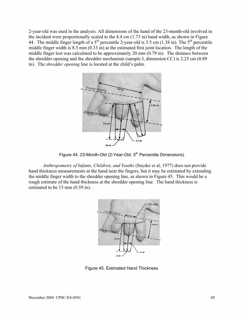
December 2004 CPSC-ES-0501 49
2-year-old was used in the analysis. All dimensions of the hand of the 23-month-old involved in the incident were proportionally scaled to the 4.4 cm (1.73 in) hand width, as shown in Figure 44. The middle finger length of a 5th percentile 2-year-old is 3.5 cm (1.38 in). The 5th percentile middle finger width is 8.3 mm (0.33 in) at the estimated first joint location. The length of the middle finger lost was calculated to be approximately 20 mm (0.79 in). The distance between the shredder opening and the shredder mechanism (sample J, dimension CC) is 2.25 cm (0.89 in). The shredder opening line is located at the child’s palm.
Figure 44. 23-Month-Old (2-Year-Old, 5th Percentile Dimensions) Anthropometry of Infants, Children, and Youths (Snyder et al, 1977) does not provide
hand thickness measurements at the hand near the fingers, but it may be estimated by extending the middle finger width to the shredder opening line, as shown in Figure 45. This would be a rough estimate of the hand thickness at the shredder opening line. The hand thickness is estimated to be 15 mm (0.59 in).
Figure 45. Estimated Hand Thickness

50 CPSC-ES-0501 December 2004
Ideally, this would be the maximum hand thickness that could fit into the shredder opening (sample J, dimension AA), which measured only 2.9 mm (0.11 in). Again, the calculations do not take into account the compressiblity of the finger/hand and the flexibility of the shredder opening. For sample J, a 9.44 mm (0.37 in) probe was inserted into the shredder opening with approximately 33.3 lbs. of force, and the shredder had a pull force of about 31.32 lbs. for 5 sheets of paper. The hand would have to compress approximately 37% of its diameter (from 15 mm (0.59 in) to 9.4 mm (0.37 in)) to fit into a shredder opening that expands from 2.9 mm (0.11 in) to 9.4 mm (0.37 in). The higher percentage of compression required for the hand (as compared to the finger of the 6-year old) does not appear unreasonable for a 2-year-old child, who would typically have a higher percentage of body fat compared to an older child.
Another method to estimate hand thickness is to use the wrist clearance measurement as
shown in Figure 46. Again, wrist clearance is not the same as hand thickness, but it may be used to calculate a rough estimate. The 5th percentile wrist thickness for a 2-year old is approximately 24 mm (0.94 in), as shown in the figure. The 5th percentile hand length for a 2-year old is approximately 88 mm (3.46 in). The 5th percentile index finger thickness at the first joint for a 2-year-old is 8.3 mm (0.33 in). Extending lines between the wrist and finger measurements, the hand thickness was estimated to be 16.4 mm (0.65 in), which is similar to the previous estimate of 15 mm (0.59 in).
In both methods for estimating hand thickness, there is uncertainty in the calculation
since there is no information to verify the estimates. However, we assume the calculation is reasonable and that the 5th percentile hand thickness for a 2-year-old is between 15 mm (0.59 in) to 16.4 mm (0.65 in). The analysis below is based on these estimates.
8.3 mmIndex Finger Diameter
88 mmHand Length
24 mm
16.4 mm
Figure 46. Illustration of Minimum Hand (wrist) Clearance In both the 23-month-old and the 6-year-old, the measured shredder openings were
smaller than the dimensions of the finger/hand of the victims. To provide additional support to the theory that both the compressibility of the finger/hand and the flexibility of the shredder openings contributed to the incidents, a series of tests was conducted using compressible probes (simulated fingers). Three sizes of compressible probes were inserted into the shredder openings of shredder samples F and G. After the 40A or 50A durometer probes were inserted into the paper shredder openings, the openings were measured. Table 11 lists the measured shredder openings. The measured shredder openings were consistently larger when a larger probe of the same durometer was inserted into the shredder opening. In most cases, the 50A durometer probes produced wider shredder openings than the 40A durometer probes of similar diameter.

December 2004 CPSC-ES-0501 51
Table 11. Shredder Openings with the Six Compressible Probes
Probe Diameter
mm (in)
DurometerSample F
mm (in)
Opening % Change
Sample J mm (in)
Opening % Change
6.8 (0.27)
40A 5.67 (0.22)
5.0% 4.03 (0.16)
39.0%
6.4 (0.25)
50A 5.80 (0.23)
7.4% 4.13 (0.16)
42.4%
9.5 (0.37)
40A 6.23 (0.25)
15.4% 5.04 (0.20)
73.8%
9.4 (0.37)
50A 7.26 (0.29)
34.4% 5.32 (0.21)
83.4%
13.0 (0.51)
40A 7.25 (0.29)
34.3% 6.51 (0.26)
124.5%
12.6 (0.50)
50A 8.47 (0.33)
56.9% 6.90 (0.27)
137.9%
For the 6-year old child, Figure 45 shows linear trend lines fitted to the data points
measured for sample F for the 40A and 50A durometer probes. A vertical line at 14 mm (0.55 in) represents the 6-year old child’s estimated finger diameter at the shredder opening. At the finger/probe diameter of 14 mm (0.55 in), the shredder opening ranges from 7.4 mm (0.29 in) to 9.2 mm (0.36 in). Since the hardness scale A is a linear scale, the estimated 45 durometer can be taken from averaging the data from the 40A and 50A durometers. The estimated flexing and finger compression for a 45 durometer probe would be approximately 8.25 mm (0.32 in). From Figure 47, it is estimated that the 14 mm (0.55 in) diameter finger (45 durometer) would have to compress to approximately 8.25 mm (0.32 in) and, similarly, the shredder opening would have to flex/expand to 8.25 mm (0.32 in).
The force required to insert an 8.25 mm (0.32 in) diameter rigid rod into the opening of
shredder sample F was estimated based on force data previously obtained using the rigid rods as shown in Figure 48. For this sample, a rod diameter of 8.25 mm (0.32 in) corresponds to a force of approximately 7 lbs. A force of 7 lbs. is required to insert the rod past the shredder opening, which is lower than the shredder mechanism pull force of 8.66 lbs (sample F) for a single sheet of paper.

52 CPSC-ES-0501 December 2004
Initial Finger/Probe Diameter vs. Final Shredder OpeningSample F
0
1
2
3
4
5
6
7
8
9
10
11
12
13
5 6 7 8 9 10 11 12 13 14 15 16 17 18 19 20
Finger/Probe Diameter (rmillimeters)
Shre
dder
Ope
ning
(mill
imet
ers)
40 Durometer50 DurometerAverageLinear (50 Durometer)Linear (40 Durometer)Linear (Average)
Figure 47. Measured and Estimated Shredder Opening, Sample F
Rod Force for Sample F
0
5
10
15
20
25
30
35
40
45
5 6 7 8 9 10 11 12 13
Rod Diameter, mm
Forc
e lb
s.
Actual Data
Figure 48. Estimated Force for an 8.25 mm Rigid Rod, Sample F For the 23-month-old child, Figure 49 shows linear trend lines fitted to data points
measured for sample J for the 40A and 50A durometer probes. The vertical lines at 15 mm (0.59 in) and 16.4 mm (0.65 in) represent the 23-month-old child’s estimated hand thickness at the shredder opening. For 15 mm (0.59 in), the shredder opening ranges from 7.9 mm (0.31 in) to

December 2004 CPSC-ES-0501 53
8.7 mm (0.34 in), and the average is approximately 8.25 mm (0.32 in)(45 durometer). For 16.4 mm (0.65 in), the shredder opening ranges from 8.6 mm (0.34 in) to 9.5 mm (0.37 in), and the average is approximately 9.0 mm (0.35 in)(45 durometer). The hand would have to compress to between 8.25 mm (0.32 in) and 9.0 mm (0.35 in), and the shredder opening would have to flex/expand to the same dimension.
The force required to insert rigid rods with diameters of 8.25 mm (0.32 in) and 9.0 mm
(0.35 in) into the opening of shredder sample J was estimated based on force data previously obtained using rigid rods. As shown in Figure 50, for this sample, rod diameters of 8.25 mm (0.32 in) and 9.0 mm (0.35 in) correspond to forces of approximately 22.2 and 27.4 lbs., respectively, to insert the rod passed the shredder opening. The shredder mechanism pull force for a single sheet of paper was only 7.49 lbs. for sample J. Five sheets of paper resulted in a pull force of 31.32 lbs.
Initial Finger/Probe Diameter vs. Final Shredder OpeningSample J
0
1
2
3
4
5
6
7
8
9
10
11
12
13
5 6 7 8 9 10 11 12 13 14 15 16 17 18 19 20
Finger/Probe Diameter (rmillimeters)
Shre
dder
Ope
ning
(mill
imet
ers)
40 Durometer50 DurometerAverageLinear (50 Durometer)Linear (Average)Linear (40 Durometer)
Figure 49. Estimated and Measured Shredder Opening, Sample J

54 CPSC-ES-0501 December 2004
Rod Force for Sample J
2
7
12
17
22
27
32
37
5 5.5 6 6.5 7 7.5 8 8.5 9 9.5 10
Rod Diameter, mm
Forc
e, lb
s.
Actual Data
Figure 50. Estimated Force for 8.25 mm and 9.0 mm Rigid Rods, Sample J The size to which a shredder opening may flex due to insertion of a foreign object greatly
depends on the hardness of the object, the initial thickness of the object, initial size of the shredder opening, and the stiffness of the shredder opening.
6.4 Housing Construction at Shredder Opening
The stiffness of a shredder opening plays an important role in preventing objects larger
than the shredder opening from contacting a shredder mechanism. The shredder housing openings of the four cross-cut shredder samples were examined. Their construction provided details as to why some shredders allowed even the largest probes to enter the shredder openings and why some did not.
Sample I did not allow the smallest rigid probe, 5.85 mm (0.23 in), to pass through the
shredder opening with approximately 33 lbs. of force. The top housing of sample I was removed to examine the interior housing construction. The plastic at the shredder opening was between 2.5 mm (0.10 in) to 2.7 mm (0.11 in) thick, as shown in Figure 51. The edge of the shredder opening contained a “rabbet” groove. The lower housing portion also contained a mating rabbet groove. When the upper and lower housings were combined, the mating “rabbet” grooves provided additional stiffness, as shown in Figure 52.

December 2004 CPSC-ES-0501 55
Underneath Top Housing
Thickness between 2.5 mm to 2.7 mm
Mating Grooves
Inlet into Shredder (with top housing removed)
Figure 51. Sample I, Shredder Opening Housing Interior
Figure 52. Illustration of Mating “Rabbet” Grooves on Housing Sample H allowed the smallest rigid probe, 5.85 mm (0.23 in), to pass through the
shredder opening with approximately 18 lbs. of force; but it did not allow the 8.63 mm (0.34 in) rigid probe to pass with approximately 50 lbs. of force. The top housing was removed to examine the interior housing construction. The plastic at the shredder opening was between 2.5 mm (0.10 in) to 3.0 mm (0.12 in) thick, as shown in Figure 53. Similar to sample I, the edge of the shredder opening contained a “rabbet” groove. The lower housing portion also contained a mating rabbet groove. When the upper and lower housings were combined, the mating “rabbet” grooves provided additional stiffness.

56 CPSC-ES-0501 December 2004
Underneath Top Housing
Thickness between 2.5 mm to 3.0 mm
Inlet into Shredder (with top housing removed)
Mating Grooves
Figure 53. Sample H, Shredder Opening Housing Interior Even though both samples contained reinforced shredder openings, sample H allowed the
smallest rigid probe, 5.85 mm (0.23 in) to pass the opening. Sample H also had a smaller shredder opening (AA) at 4.4 mm (0.17 in) compared to sample I at 4.9 mm (0.19 in). The initial shredder opening (DD) and depth of the opening (BB-CC) may have been the differences between samples H and I that allowed the rod to pass the shredder opening for H and not I. Sample I had a wider initial shredder opening (DD) at 17.1 mm and a deeper opening (BB-CC) at 32.9 mm (1.30 in) than sample H.
Figure 54 shows an illustration of the differences between samples H and I. The figure
does not show the actual curvatures of the shredder openings, but it does show the scaled differences. A shredder with longer taper at the shredder opening may actually help prevent a rod from passing through the opening compared to a shredder that has less taper. With the longer tapered opening, as the rod was being inserted into the opening, the shredder opening flexed outward and caused the rod to bind against the housing.

December 2004 CPSC-ES-0501 57
Does not represent actual shredder opening curvatures.
Figure 54. Partial Illustration of Shredder Opening
Sample G allowed the 9.44 mm (0.37 in) rigid probe, the third largest probe, to pass
through the shredder opening with approximately 16 lbs. of force; but it did not allow the largest rigid probe, 12.24 mm (0.48 in), to pass with approximately 50 lbs. of force. The largest rigid probe would catch on the lower portion of the housing, as mentioned previously.
The top housing was removed to examine the interior housing construction. The plastic
at the shredder opening was between 2.3 mm (0.09 in) to 2.5 mm (0.10 in) thick, as shown in Figure 55. The upper housing interior contained stiffeners to help prevent the shredder opening from flexing. The stiffeners were spaced 41.2 mm (1.62 in), 58.6 mm (2.31 in), and 46.5 mm (1.83 in) apart. Unlike samples I and H, the edges of the shredder opening did not contain mating “rabbet” grooves to help prevent the shredder opening from expanding. The upper housing did contain notches to help prevent the shredder opening from reducing in size, but it did not prevent the shredder opening from expanding, as illustrated in Figure 56.
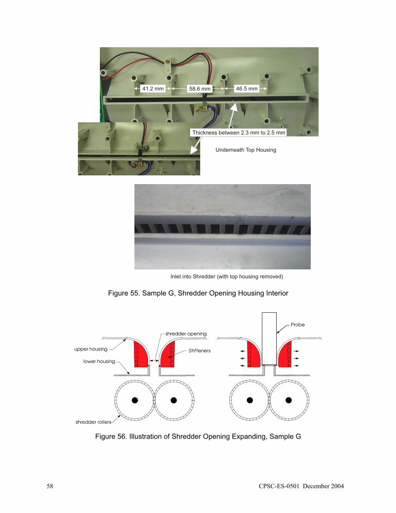
58 CPSC-ES-0501 December 2004
Underneath Top Housing
Inlet into Shredder (with top housing removed)
Thickness between 2.3 mm to 2.5 mm
58.6 mm 46.5 mm41.2 mm
Figure 55. Sample G, Shredder Opening Housing Interior
Figure 56. Illustration of Shredder Opening Expanding, Sample G

December 2004 CPSC-ES-0501 59
Similar to sample G, sample J allowed passage of the 9.44 mm (0.37 in) rigid probe, the third largest probe; but did not allow the largest rigid probe, 12.24 mm (0.48 in) to pass the shredder opening. The top housing was removed to examine the interior housing construction. The plastic at the shredder opening was approximately 1.83 mm (0.07 in) thick, as shown in Figure 57. Unlike samples I and H, the edges of the shredder opening did not contain mating “rabbet” grooves to help prevent the shredder opening from expanding.
Thickness approximately 1.83 mm
Figure 57. Sample J, Shredder Opening Housing Interior
Sample F allowed the 12.24 mm (0.48 in) rigid probe, the largest probe, to pass through the shredder opening with approximately 40 lbs. of force. The top housing was removed to examine the interior housing construction. The plastic at the shredder opening was approximately 3.0 mm (0.12 in) thick, as shown in Figure 58. Unlike sample G, the interior of the upper housing did not contain any stiffeners to help prevent the shredder opening from flexing. Also, it did not contain any mating “rabbet” grooves with the lower portion of the housing to help prevent the shredder opening from expanding. The lower portion of the housing was open at the shredder mechanism intake, as shown in the figure.

60 CPSC-ES-0501 December 2004
Underneath Top Housing
Thickness 3 mm
Inlet into Shredder (with top housing removed)
Figure 58. Sample F Shredder Opening Housing Interior 6.5 Analysis of Maximum Shredder Opening to Prevent Injury
It has been shown that several factors - the initial size of the shredder opening, the
amount of shredder opening flexing, the size of the compressible finger, and the force to either push or pull a compressible finger - are needed to determine if the finger can contact a shredder mechanism. This section will examine the possible maximum shredder opening to prevent finger injury. Some variables will have to be assumed in this analysis. For example, it is assumed that the shredder housing is designed and constructed in a manner that does not allow it to flex under 20 lbs. of force and the youngest age group used as a baseline for preventing finger injuries is the 5th percentile 13- to 18-month-old. Twenty lbs. of force was chosen to represent the average pull force for 3 sheets of paper with a cross-cut shredder.
The estimated index finger diameter for the 5th percentile 13- to 18-month-old is 7.8 mm
(0.31 in). Unfortunately, none of the finger probe samples used in Section 5.5 testing had a diameter of 7.8 mm (0.31 in). The resulting thickness of a 7.8 mm (0.31 in) finger diameter compressed using 20 lbs. of force was estimated from the compressible probe diameters used in Section 5.5. To determine the finger thickness from 20 lbs. of applied force, the compressible

December 2004 CPSC-ES-0501 61
fingers were compressed using a force gauge and the resulting finger thicknesses were measured with feeler gauges as shown in Figure 59.
Figure 59. Finger Probes Compression Setup
The three sizes of 40A and 50A durometer probes were compressed with 20 lbs. of force, and the resulting thicknesses were measured. The 40A and 50A durometer data were averaged to estimate the 45-durometer curve as shown in Figure 60. For an 7.8 mm (0.31 in) index finger diameter that represents a 5th percentile 13- to 18-month-old, the finger compressed (44%) to approximately 4.4 mm (0.17 in) from 20 lbs. of applied force. In this example, the analysis shows that if a shredder opening was designed and constructed to have an opening of 4.4 mm (0.17 in) and could not flex from 20 lbs. of force, a 5th percentile 13- to 18-month-old child’s index finger would not likely be drawn into the paper shredder mechanism. A shredder opening of 4.4 mm (0.17 in) does not account for any margin of safety. A different age group, percentile for the age group, and applied force would affect the resulting estimated maximum shredder opening in preventing injury.

62 CPSC-ES-0501 December 2004
Finger Probes Compressed (20 lbs. of force)
0
1
2
3
4
5
6
7
8
9
10
11
12
5 6 7 8 9 10 11 12 13 14
Finger/Probe Diameter (millimeters)
Com
pres
sed
Fing
er (m
m)
40 Durometer50 DurometerAverageLinear (50 Durometer)Linear (Average)Linear (40 Durometer)
Figure 60. Finger Probes Compressed with Force of 20 lbs. 6.6 Warnings and Cautions on Paper Shredders
The hazard markings on the sample paper shredders were generally consistent. The
shredders usually displayed two symbols that represented “keep fingers/hands away” from the shredder opening and “keep ties or other dangling objects” from the shredder opening, as shown in Figure 61. Some shredders had additional warning symbols including “no paper clips” or the maximum number of sheets per pass. Table 12 lists the markings near the shredder openings for the ten samples.
Figure 61. Hazard Symbols for Paper Shredders

December 2004 CPSC-ES-0501 63
Table 12. Warning and Caution Markings on Shredders
Sample Keep fingers
and hand away
Keep long or dangling objects
away
Maximum Sheets
Other Cautions or Warnings near
opening Notes
A Yes Yes Yes 1) Caution Symbol 2) No Paper Clips
1) All Symbols Contrasting colors
B Yes Yes No 1) No Paper Clips 1) Strip-cut symbol 2) No contrasting colors
C Yes Yes Yes 1) Paper Only Symbol 1) Max. number of sheets contrasting only
D Yes Yes No 1) No Necklace 2) No Long Hair 3) Caution Symbol
1) No contrasting colors
E Yes Yes Yes 1) No Paper Clips 1) Release symbol 2) All Symbols Contrasting
colors
F No No Yes None 1) No contrasting colors
G Yes Yes Yes 1) No Paper Clips 1) Max. number of sheets contrasting colors only
H Yes Yes Yes 1) Paper Only Symbol 1) All Symbols Contrasting colors
I Yes Yes Yes 1) No Paper Clips 2) No Aerosol Sprays 3) Oil OK
1) All Symbols Contrasting colors
J Yes Yes Yes 1) No Paper Clips 1) Max. number of sheets contrasting colors only
Shredder sample F did not contain any hazard symbols near the shredder opening. Only
the maximum number of sheets per pass was labeled near the shredder opening. Some shredders had contrasting colors for the hazard symbols and the housing color, whereas some shredders had the same color for the hazard symbols and the housing color, as shown in Figure 62.
Contrasting Colors
Same Color as the Housing
Figure 62. Visibility of Hazard Symbols
None of the shredders contained any hazard or caution symbols that would indicate, “Children should NOT operate the shredder.” While this warning would seem appropriate, adults who have had past positive experiences with this product may ignore it. Further, adults may believe that their child can safely use the product if the child is closely supervised.

64 CPSC-ES-0501 December 2004
A child’s fingers can be drawn into the shredder opening before the adult can react quickly enough to stop the shredder or pull the child’s fingers from the shredder opening. In the incidents mentioned earlier, children’s fingers have been amputated even though parents were supervising the children using the shredder. Therefore, a warning label on the product may not be the most effective means of addressing the hazard.
For some of the shredder samples, the function switch settings also did not have
contrasting colors from the housings, as shown in Figure 63. Non-contrasting colors may make it more likely that an operator could set the function switch to an incorrect position. For example, a function switch that contains Off, Auto, Forward, and Reverse positions may be more difficult to set in the desired position if the label/text and the housing are the same color. If the operator had to quickly switch the shredder off, reading the off position may be difficult.
Contrasting Colors
Same Color as the Housing
Figure 63. Visibility of Control Functions

December 2004 CPSC-ES-0501 65
7.0 OBSERVATIONS
Observations are based on the samples tested, not a statistical sampling nor a sample of
all types of paper shredders. Product Characteristics • The cross-cut shredders allowed larger rigid rods to pass the shredder openings than did
the strip-cut shredders. • The pull force of the shredder mechanism was consistently higher for cross-cut shredders
than for strip-cut shredders. • By observation, the cross-cut shredders allowed the smallest compressible probe to be
drawn into the shredder mechanisms more easily than did the strip-cut shredders. • The cross-cut shredders allowed larger compressible probes to be drawn into the shredder
mechanisms than did the strip-cut shredders. Function Switches • Only some shredders had an Off position on the function switch. • No shredders tested had an On/Off switch separate from the shredder mechanism
functions (Auto, Forward, Reverse). Markings/Symbols • Not all the paper shredders contained the same hazard markings at the shredder opening. • Some shredders did not have constrasting colors for the hazard markings. • Some shredders did not have constrasting colors for the function markings.

66 CPSC-ES-0501 December 2004
No Text on This Page

December 2004 CPSC-ES-0501 67
8.0 CONCLUSIONS
Conclusions are based on the samples tested, not a statistical sampling nor a sample of all
types of paper shredders.
Hazard • Paper shredders pose the greatest risk of finger injuries to children between the ages of 15
months and 2 ½ years (based on incident data). • The level of risk and seriousness of the hazard is dependent on the design of the shredder
opening (see Product Characteristics below).
Voluntary Standard
• The probes currently specified in UL 60950 and IEC 60950 to test accessibility to hazardous moving parts do not capture hazards involving children.
• The Articulate Probe may be a good indication of which paper shredders may pose a finger hazard for older children, when the appropriate force is applied during testing; but it may not capture hazards for children as young as 15 months old.
Product Characteristics
• The design of the shredder opening determines the amount of force required to insert (or
not insert) a probe into the shredder opening. Contributing factors include, but are not limited to: width of opening, stiffness of opening, distance to shredder mechanism, compressibility of fingers, and shredding mechanism pull force.

68 CPSC-ES-0501 December 2004
No Text on This Page

December 2004 CPSC-ES-0501 69
9.0 REFERENCES ASTM. 2001. Standard Practice for Contact Closure Cycling of a Membrane Switch. Designation: F
1578-01, West Conshohocken, PA. ASTM. 2003. Standard Test Method for Rubber Property – Durometer Hardness. Designation: D 2240-
03, West Conshohocken, PA. Federal Trade Commission. September 2003. Identity Theft Survey Report. Prepared by Synovate, International Standard. 2001. IEC (International Electrotechnical Commission), Information technology
equipment – Safety – Part 1: General Requirements. CEI IEC 60950-1, First edition 2001-10, Geneva, Switzerland.
International Standard. 1997. IEC (International Electrotechnical Commission), Protection of persons and
equipment by enclosures – Probes for verification, CEI IEC 61032, Second edition 1997-12, Geneva, Switzerland.
Peters, M; Mackenzie, K.; and Bryden, P. 2002. “Finger Length and Distal Finger Extent patterns in
Humans.” American Journal of Physical Anthropology 117: 209-217. Snyder, R.; Schneider, L.; Owings, C.; Reynolds, H.; Golomb, D.; and Schork, M. (1977). Anthropometry
of Infants,Children, and Youths to Age 18 for Product Safety Design. Report No. UM-HSRI-BI-77-17, Contract No. CPSC-C-75-0068. Prepared for the Consumer Product Safety Commission. Ann Arbor, MI: Highway Safety Research Institute, The University of Michigan.
Snyder, R; Spencer, M.; Owings, C.; and Schneider, L. (1975). Physical Characteristics of Children as
Related to Death & Injury for Consumer Product Safety Design. Report No. UM-HSRI-BI-75-5, Contract No. FDA 72-70. Prepared for Consumer Product Safety Commission. Ann Arbor, MI: Highway Safety Research Institute, The University of Michigan.
Underwriters Laboratories Inc. April 1, 2003. Information Technology Equipment – Safety – Part 1:
General Requirements. UL 60950-1, First Edition, Northbrook, Illinois. U.S. Code of Federal Regulations (CFR), Title 16, Volume 2, Chapter 11, Part 1500.

70 CPSC-ES-0501 December 2004
No Text on This Page

December 2004 CPSC-ES-0501 71
Appendix Auto Start/Stop Auto Start/Stop feature allows the machine to turn on when paper is
inserted into the paper shredder opening. The shredder automatically stops when it has completed shredding the paper. (Auto, Auto On/Off).
Cross-cut The shredded output is cut lengthwise and widthwise, creating between
500 and 800 confetti-like paper particles per letter-size sheet. Document Shredder A product used to shred paper (Paper Shredder, Shredder). Forward Function Forward function feature runs the machine continuously (For, Forward,
On). Shredder Opening The gap of the shredder throat for the paper. The gap between different
shredder designs can vary significantly, but is usually less than 7/16”. (Shredder Gap, Gap)
Shredder Rollers The mechanism that cuts the paper. Strip-cut The shredded output is cut lengthwise into long strips (Straight-cut). Off Switch Removes power from the unit. The shredder cannot be activated if paper is
inserted into the shredder intake opening (Off). Paper Capacity The number of paper sheets that can be fed into the shredder at one time or
per pass. Reverse Function Reverses the rotation of the shredder rollers. Reverse function feature
helps the user clear paper jams easily (Reverse, Rev). Throat The width or size of the shredder intake opening. The opening usually
varies between 8 ¾” to 9 ½” (Paper Width).

72 CPSC-ES-0501 December 2004
No Text on This Page

Additional headquarters contact information Toll-free consumer hotline: 800-638-2772 (TTY 800-638-8270). Call to obtain product safety information and other agency information and to report unsafe products. Available 24 hours a day, 7 days a week. Compliance information 301-504-7912 [email protected] Commission meeting agendas 301-504-7923 [email protected] Employee locator 301-504-6816 Employment information 301-504-7925 [email protected] Freedom of Information Act 301-504-7923 [email protected] Media relations/Information and Public Affairs 301-504-7908 National Injury Information Clearinghouse 301-504-7921 [email protected] Office of the Executive Director 301-504-7907 Office of the General Counsel 301-504-7922 Publications [email protected]

Headquarters Mailing address: U.S. Consumer Product Safety Commission Washington, D.C. 20207-0001 Street address: 4330 East-West Highway Bethesda, Maryland 20814-4408 Tel. (800) 638-2772 Fax (301) 504-0124 and (301) 504-0025 E-mail: [email protected] Regional Offices Eastern 201 Varick Street, Room 903 New York, NY 10014-4811 Tel. (212) 620-4120 Central 230 South Dearborn Street, Room 2944 Chicago, IL 60604-8260 Tel. (312) 353-8260 Western 1301 Clay Street, Suite 610-N Oakland, CA 94612-5217 Tel. (510) 637-4050
U.S. CONSUMER PRODUCT SAFETY COMMISSION