Aerodynamic and aeroacoustic optimization of a centrifugal ...

National Aeronautics and Space Administration
www.nasa.gov
An assessment of NASA Glenn’s
aeroacoustic experimental and predictive
capabilities for installed cooling fans
Part 1: Aerodynamic performance
Dale E. Van Zante
L. Danielle Koch
Mark P. Wernet
Gary G. Podboy
NASA Glenn Research Center
Cleveland, OH
Internoise 2006, Honolulu, Hawaii
GE90 turbofan engine for the Boeing 777

National Aeronautics and Space Administration
www.nasa.gov
Objective: to determine if aircraft engine
design and analysis techniques for
performance and low noise are
applicable to cooling fans
Rolls-Royce Trent 1000 fan for the A380
Aircraft engine fan design goals:
• efficiency
• durability
• low noise
• reduced cost
The technological evolution of aircraft enginefans is driven by the use of 3D computationalmethods and experimental measurements.
What is the design maturity of cooling fans
relative to aircraft engine fans?
National Aeronautics and Space Administration
www.nasa.gov
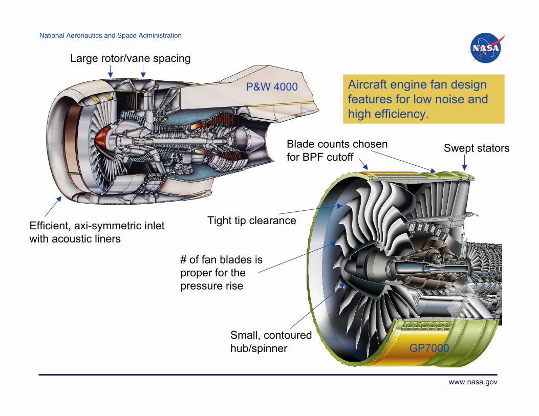
Efficient, axi-symmetric inlet
with acoustic liners
Large rotor/vane spacing
Small, contoured
hub/spinner
Tight tip clearance
Blade counts chosen
for BPF cutoffSwept stators
P&W 4000
GP7000
Aircraft engine fan design
features for low noise and
high efficiency.
# of fan blades is
proper for the
pressure rise

National Aeronautics and Space Administration
www.nasa.gov
69,000 Pa19 PaPressure rise
446,000 m3/hr40 m3/hrFlow
544Struts/stators
225Rotor blades
1.70.86Solidity
0.5%2.9%Clr/chord
94 mm34 mmBlade chord
0.5 mm1 mmClr height
370 m/s12.8 m/sTip speed
12, 657 rpm3,300 rpmOperating speed
0.300.70Hub/Tip ratio
83.8 mm26 mmHub radius
278.9 mm37 mmTip radius
279.4 mm38 mmCasing radius
Aircraft Fan
Model
Cooling
Fan
A representative axial fan which was
tested for its aeroperformance and
acoustic characteristics.

National Aeronautics and Space Administration
www.nasa.gov
Testing the fan on the automated
plenum in the Glenn Acoustic
Testing Laboratory (ATL)
The fan was tested with and without an inlet duct.
The duct contained a wall static tap to determine the
fan inlet pressure.Wall static tap

National Aeronautics and Space Administration
www.nasa.gov
Cooling fan pressure rise and sound power characteristics
• the inlet duct increased pressure rise and decreased sound power at the fan
peak efficiency operating point
• detailed fan flowfield measurements will help explain the performance increase
and will also show how the fan flowfield deteriorates at stall onset
Sta
ll onset
Fre
e d
eliv
ery
Peak e
ff.

National Aeronautics and Space Administration
www.nasa.gov
Fan flow field measurements were
acquired using Particle Image
Velocimetry (PIV)
• flow fields are average of 200
vector maps
• data are phase locked to the rotor
using the tach signal
• free delivery and mild stall
operating conditions
FLOW
3D PIV illumination plane
2D PIV illumination plane
rotor
National Aeronautics and Space Administration
www.nasa.gov
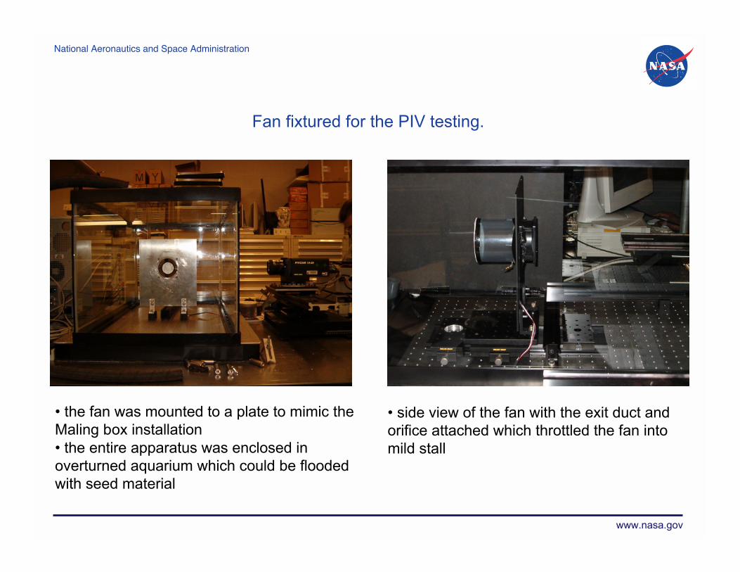
Fan fixtured for the PIV testing.
• the fan was mounted to a plate to mimic the
Maling box installation
• the entire apparatus was enclosed in
overturned aquarium which could be flooded
with seed material
• side view of the fan with the exit duct and
orifice attached which throttled the fan into
mild stall

National Aeronautics and Space Administration
www.nasa.gov
Why did the fan pressure rise increase
when an inlet duct was added?
X mm0 25 50 75 100 125
U m/s
0.6
0.2
-0.2
-0.6
-1
-1.4
-1.8
-2.2
-2.6
-3
-3.4
-3.8
-4.2
rotor
Without a duct, the flow is
unable to negotiate the
sharp inlet lip.
The outer blade spans,
where blade speed is
highest, are not able to do
useful work.
The duct guides flow into
the rotor and allows more
of the blade span to do
useful work, thus the
pressure rise is increased.
2D PIV at the fan centerline, free delivery condition.

National Aeronautics and Space Administration
www.nasa.gov
Why did the fan sound power decrease
when an inlet duct was added?
3D PIV on a plane 12.5mm in front of fan, free
delivery condition.
• fan inflow shows the ‘imprint’
of the partial bellmouth in the
fan inlet geometry
• the inlet flow distortion is a
tone noise source
• the fan inlet duct made the fan
inflow more axisymmetric and
thus decreased noise

National Aeronautics and Space Administration
www.nasa.gov
Cooling fan pressure rise and sound power characteristics
Sta
ll onset
Fre
e d
eliv
ery
Peak e
ff.

National Aeronautics and Space Administration
www.nasa.gov
rotor
Meridional view, 2D PIV, mild stall. Fan inlet, 3D PIV, mild stall.
Swirling flow comes OUT of the inlet (red regions in above images) and leaks
preferentially at the partial bellmouth cutouts.
Air that the fan is meant to exhaust is recirculated instead.
What happens if the fan is mismatched to
the system and operates in mild stall?
National Aeronautics and Space Administration
www.nasa.gov
Discussion
It is unclear as to the origin of certain geometric design features of the
cooling fan, although we can speculate that, for example:
- the motor form factor choice results in a large hub/tip ratio
- the drive to low manufacturing cost results in large tip clearance
- the ‘partial bellmouth’ in the fan casing is due to ????
Cooling fans are now expected to be a pressure rise device and more
attention to aerodynamics will be necessary to achieve the desired aero
performance at acceptable sound power levels.
For example, Wang and Huang (INCE Journal, Jan-Feb. 2006) showed a 2.5 dB
decrease in overall sound power when the partial bellmouth was replaced with an
axisymmetric inlet on a typical computer cooling fan.

National Aeronautics and Space Administration
www.nasa.gov
Summary
Aircraft engine systems do provide guidance for low noise, high
performance design characteristics.
Tools for aircraft fan diagnostics, analysis, and design could help identify
noise sources and generally improve the aero and acoustic performance
of cooling fans.
We feel that there is significant gains to be made in cooling fan aero
design and installation. (For example, a good inlet design could reduce
overall sound power by 2.5dB)
There are some fan manufacturers taking advantage of aircraft engine
design tools. The aero performance of these fans is impressive. We
would like to investigate the acoustic characteristics of these new fan
designs.

National Aeronautics and Space Administration
www.nasa.gov
Questions?
http://www.grc.nasa.gov/WWW/Acoustics/collaboration/focusonfans.htm

National Aeronautics and Space Administration
www.nasa.gov
Examples of improved design practice
Intake
Exhaust