An approximate method for calculating total ship ...
8
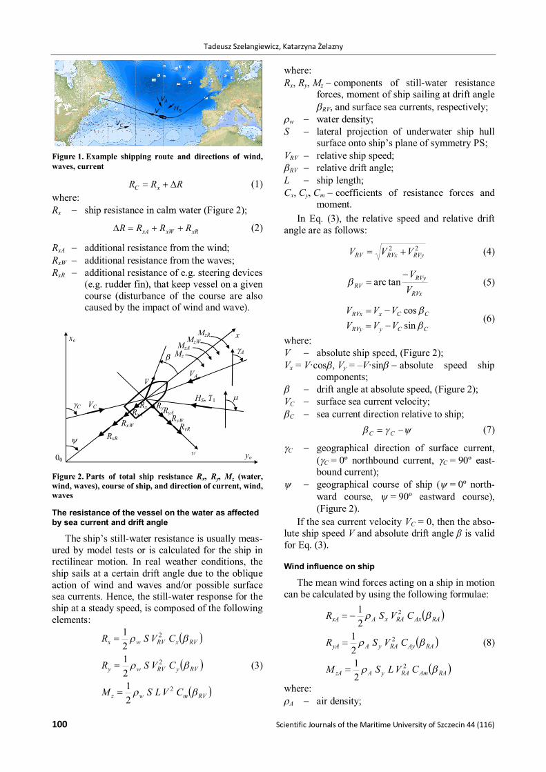
Zeszyty Naukowe Akademii Morskiej w Szczecinie 44 (116) 99 Scientific Journals Zeszyty Naukowe of the Maritime University of Szczecin Akademii Morskiej w Szczecinie 2015, 44 (116), 99–106 ISSN 1733-8670 (Printed) Received: 16.07.2015 ISSN 2392-0378 (Online) Accepted: 10.09.2015 DOI: 10.17402/063 Published: 07.12.2015 An approximate method for calculating total ship resistance on a given shipping route under statistical weather conditions and its application in the initial design of container ships Tadeusz Szelangiewicz 1 , Katarzyna Żelazny 2 1 Maritime University of Szczecin, Faculty of Navigation 1–2 Wały Chrobrego St., 70-500 Szczecin, Poland, e-mail: [email protected] 2 West Pomeranian University of Technology Szczecin, Faculty of Maritime Technology and Transport 41 Piastów Avenue, 71-065 Szczecin, Poland, e-mail: [email protected] corresponding author Key words: ship resistance, approximate method, wind, waves, current, rudder, ship containers Abstract During ship design, its service speed is one of the crucial parameters that determine its future operational profitability. As sufficiently exact calculation methods applicable to preliminary design stage are lacking, the so-called contract speed, the speed a ship reaches in calm water, is usually specified during the draft stage. The service speed obtainable by a ship under real weather conditions (mainly wind and waves) is one of the most important parameters influencing a ship’s profitability on a given shipping route. This paper presents a parametric model of calculating total ship resistance on a given shipping route under actual weather conditions (wind, waves, sea current), that could be useful in the initial design of container ships. Introduction During ship design, one of the parameters most crucial to the operational profitability of a ship is its service speed under seasonal weather conditions. The service speed and total resistance of a ship can be determined during its operation, or calculated on the basis of complete design documentation or from the results of model basin tests. An algorithm for estimating total ship resistance (resistance on calm water, plus resistance from wind, waves, sea cur- rents and rudder adjustments) was presented in Szelangiewicz and Żelazny (Szelangiewicz & Żelazny, 2006). This method cannot, however, be used in preliminary stages of ship design, when important decisions must now be made only on the basis of the ship’s hull geometry, which has been the only information a ship designer typically has at his disposal during the initial design stages. The details of hull geometry are insufficient to allow service speed under expected weather conditions to be estimated. This article presents an approximate method of estimating a ship’s resistance on calm water, as well as the additional resistance from wind, waves, sea currents and rudder adjustments that would be useful to know in the preliminary design of a con- tainer ship (additional resistance from waves was presented in Żelazny (Żelazny, 2015). The total resistance of the vessel on a given shipping route While a transport vessel sails on a given ship- ping route (Figure 1) under real weather conditions, acted on by wind, waves and currents, then addi- tional resistance as well as drift moments appear and, in order to keep the vessel on a constant course, these drift moments must be counterbal- anced by a rudder plane and resulting carrying helm. The total resistance of the vessel under real weather conditions on a given shipping route is given by the following expression:
Transcript of An approximate method for calculating total ship ...

Zeszyty Naukowe Akademii Morskiej w Szczecinie 44 (116) 99
Scientific Journals Zeszyty Naukowe of the Maritime University of Szczecin Akademii Morskiej w Szczecinie
2015, 44 (116), 99–106 ISSN 1733-8670 (Printed) Received: 16.07.2015 ISSN 2392-0378 (Online) Accepted: 10.09.2015 DOI: 10.17402/063 Published: 07.12.2015
An approximate method for calculating total ship resistance on a given shipping route under statistical weather conditions and its application in the initial design of container ships
Tadeusz Szelangiewicz1, Katarzyna Żelazny2
1 Maritime University of Szczecin, Faculty of Navigation 1–2 Wały Chrobrego St., 70-500 Szczecin, Poland, e-mail: [email protected]
2 West Pomeranian University of Technology Szczecin, Faculty of Maritime Technology and Transport 41 Piastów Avenue, 71-065 Szczecin, Poland, e-mail: [email protected] corresponding author
Key words: ship resistance, approximate method, wind, waves, current, rudder, ship containers
Abstract During ship design, its service speed is one of the crucial parameters that determine its future operational profitability. As sufficiently exact calculation methods applicable to preliminary design stage are lacking, the so-called contract speed, the speed a ship reaches in calm water, is usually specified during the draft stage. The service speed obtainable by a ship under real weather conditions (mainly wind and waves) is one of the most important parameters influencing a ship’s profitability on a given shipping route. This paper presents a parametric model of calculating total ship resistance on a given shipping route under actual weather conditions (wind, waves, sea current), that could be useful in the initial design of container ships.
Introduction During ship design, one of the parameters most
crucial to the operational profitability of a ship is its service speed under seasonal weather conditions. The service speed and total resistance of a ship can be determined during its operation, or calculated on the basis of complete design documentation or from the results of model basin tests. An algorithm for estimating total ship resistance (resistance on calm water, plus resistance from wind, waves, sea cur-rents and rudder adjustments) was presented in Szelangiewicz and Żelazny (Szelangiewicz & Żelazny, 2006). This method cannot, however, be used in preliminary stages of ship design, when important decisions must now be made only on the basis of the ship’s hull geometry, which has been the only information a ship designer typically has at his disposal during the initial design stages. The details of hull geometry are insufficient to allow service speed under expected weather conditions to be estimated.
This article presents an approximate method of estimating a ship’s resistance on calm water, as well as the additional resistance from wind, waves, sea currents and rudder adjustments that would be useful to know in the preliminary design of a con-tainer ship (additional resistance from waves was presented in Żelazny (Żelazny, 2015).
The total resistance of the vessel on a given shipping route
While a transport vessel sails on a given ship-ping route (Figure 1) under real weather conditions, acted on by wind, waves and currents, then addi-tional resistance as well as drift moments appear and, in order to keep the vessel on a constant course, these drift moments must be counterbal-anced by a rudder plane and resulting carrying helm.
The total resistance of the vessel under real weather conditions on a given shipping route is given by the following expression:
Tadeusz Szelangiewicz, Katarzyna Żelazny
100 Scientific Journals of the Maritime University of Szczecin 44 (116)
RRR xC (1) where: Rx ship resistance in calm water (Figure 2);
xRxWxA RRRR (2)
RxA additional resistance from the wind; RxW additional resistance from the waves; RxR additional resistance of e.g. steering devices
(e.g. rudder fin), that keep vessel on a given course (disturbance of the course are also caused by the impact of wind and wave).
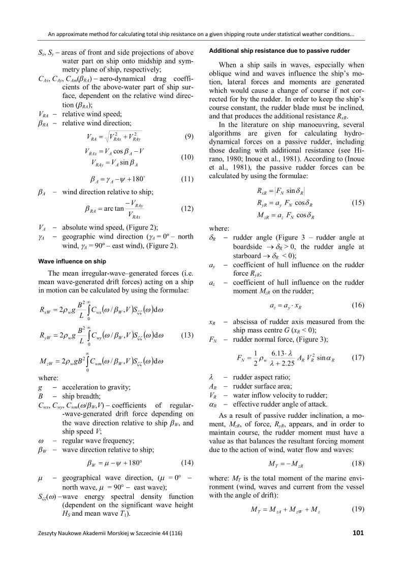
Figure 2. Parts of total ship resistance Rx, Ry, Mz (water, wind, waves), course of ship, and direction of current, wind, waves
The resistance of the vessel on the water as affected by sea current and drift angle
The ship’s still-water resistance is usually meas-ured by model tests or is calculated for the ship in rectilinear motion. In real weather conditions, the ship sails at a certain drift angle due to the oblique action of wind and waves and/or possible surface sea currents. Hence, the still-water response for the ship at a steady speed, is composed of the following elements:
RVmwz
RVyRVwy
RVxRVwx
CVLSM
CVSR
CVSR
2
2
2
21
2121
(3)
where: Rx, Ry, Mz components of still-water resistance
forces, moment of ship sailing at drift angle RV, and surface sea currents, respectively;
w water density; S lateral projection of underwater ship hull
surface onto ship’s plane of symmetry PS; VRV relative ship speed; RV relative drift angle; L ship length; Cx, Cy, Cm coefficients of resistance forces and
moment. In Eq. (3), the relative speed and relative drift
angle are as follows:
22RVyRVxRV VVV (4)
RVx
RVyRV V
V tanarc (5)
CCyRVy
CCxRVx
VVVVVV
sincos
(6)
where: V absolute ship speed, (Figure 2); Vx = V·cos, Vy = –V·sin absolute speed ship
components; drift angle at absolute speed, (Figure 2); VC surface sea current velocity; C sea current direction relative to ship; CC (7)
C geographical direction of surface current, (C = 0º northbound current, C = 90º east-bound current);
geographical course of ship ( = 0º north-ward course, = 90º eastward course), (Figure 2).
If the sea current velocity VC = 0, then the abso-lute ship speed V and absolute drift angle β is valid for Eq. (3).
Wind influence on ship
The mean wind forces acting on a ship in motion can be calculated by using the following formulae:
RAAmRAyAzA
RAAyRAyAyA
RAAxRAxAxA
CVLSM
CVSR
CVSR
2
2
2
21
21
21
(8)
where: A air density;
VC
y
C
x
V
yo
xo
00
HS, T1
VA
A MzA MzW
Mz
RxA
RxW
Rx
RyW
Ry RyA
RxR
RyR
MzR
Figure 1. Example shipping route and directions of wind, waves, current
HS
VA
VC
V HS
VA
VC
V
An approximate method for calculating total ship resistance on a given shipping route under statistical weather conditions...
Zeszyty Naukowe Akademii Morskiej w Szczecinie 44 (116) 101
Sx, Sy areas of front and side projections of above water part on ship onto midship and sym-metry plane of ship, respectively;
CAx, CAy, CAm(RA) aero-dynamical drag coeffi-cients of the above-water part of ship sur-face, dependent on the relative wind direc-tion (RA);
VRA relative wind speed; RA relative wind direction;
22RAyRAxRA VVV (9)
AARAy
AARAx
VVVVV
sincos
(10)
180 AA (11)
A wind direction relative to ship;
RAx
RAyRA V
V tan arc (12)
VA absolute wind speed, (Figure 2); A geographic wind direction (A = 0º– north
wind, A = 90º– east wind), (Figure 2).
Wave influence on ship
The mean irregular-wave–generated forces (i.e. mean wave-generated drift forces) acting on a ship in motion can be calculated by using the formulae:
d,/20
2
SVCL
BgR WwxwxW
d,/20
2
SVCLBgR WwywyW (13)
d,/20
2
SVCgBM WwmwzW
where: g acceleration to gravity; B ship breadth; Cwx, Cwy, Cwm(/W,V) coefficients of regular-
-wave-generated drift force depending on the wave direction relative to ship W, and ship speed V;
regular wave frequency; W wave direction relative to ship;
180W (14)
geographical wave direction, ( = 0 north wave, = 90 east wave);
S() wave energy spectral density function (dependent on the significant wave height HS and mean wave T1).
Additional ship resistance due to passive rudder
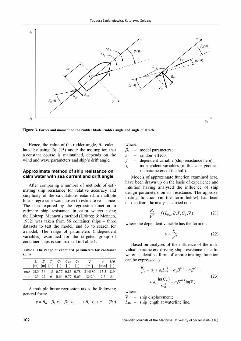
When a ship sails in waves, especially when oblique wind and waves influence the ship’s mo-tion, lateral forces and moments are generated which would cause a change of course if not cor-rected for by the rudder. In order to keep the ship’s course constant, the rudder blade must be inclined, and that produces the additional resistance RxR.
In the literature on ship manoeuvring, several algorithms are given for calculating hydro-dynamical forces on a passive rudder, including those dealing with additional resistance (see Hi-rano, 1980; Inoue et al., 1981). According to (Inoue et al., 1981), the passive rudder forces can be calculated by using the formulae:
RNzzR
RNyyR
RNxR
FaM
FaRFR
cos
cossin
(15)
where: R rudder angle (Figure 3 – rudder angle at
boardside R > 0, the rudder angle at starboard R < 0);
ay coefficient of hull influence on the rudder force RyR;
az coefficient of hull influence on the rudder moment MzR on the rudder;
Ryz xaa (16)
xR abscissa of rudder axis measured from the ship mass centre G (xR < 0);
FN rudder normal force, (Figure 3);
RRRwN VAF
sin25.2
13.621 2
(17)
rudder aspect ratio; AR rudder surface area; VR water inflow velocity to rudder; R effective rudder angle of attack.
As a result of passive rudder inclination, a mo-ment, MzR, of force, RyR, appears, and in order to maintain course, the rudder moment must have a value as that balances the resultant forcing moment due to the action of wind, water flow and waves:
zRT MM (18)
where: MT is the total moment of the marine envi-ronment (wind, waves and current from the vessel with the angle of drift):
zzWzAT MMMM (19)
Tadeusz Szelangiewicz, Katarzyna Żelazny
102 Scientific Journals of the Maritime University of Szczecin 44 (116)
Hence, the value of the rudder angle, R, calcu-lated by using Eq. (15) under the assumption that a constant course is maintained, depends on the wind and wave parameters and ship’s drift angle.
Approximate method of ship resistance on calm water with sea current and drift angle
After comparing a number of methods of esti-mating ship resistance for relative accuracy and simplicity of the calculations entailed, a multiple linear regression was chosen to estimate resistance. The data required by the regression function to estimate ship resistance in calm waters using the Holtrop–Mennen’s method (Holtrop & Mennen, 1982) was taken from 56 container ships – three datasets to test the model, and 53 to search for a model. The range of parameters (independent variables) examined for the targeted group of container ships is summarized in Table 1.
Table 1. The range of examined parameters for container ships
L [m]
B [m]
T [m]
CB [–]
CWP [–]
CP [–]
[m3]
V [m/s]
L/B [–]
max 380 56 15 0.77 0.85 0.78 214580 13.5 8.9 min 125 22 6 0.64 0.77 0.65 12420 2.5 5.4
A multiple linear regression takes the following
general form:
kk xxxy ...22110 (20)
where: i – model parameters; – random effects; y – dependent variable (ship resistance here); xi – independent variables (in this case geomet-
ric parameters of the hull). Models of approximate function examined here,
have been drawn up on the basis of experience and intuition having analysed the influence of ship design parameters on its resistance. The approxi-mating function (in the form below) has been chosen from the analysis carried out:
),,,,(2 BWLT CTBLf
VR (21)
where the dependent variable has the form of:
2VRy T (22)
Based on analyses of the influence of the indi-vidual parameters driving ship resistance in calm water, a detailed form of approximating function can be expressed as:
)ln()ln( 5.0
524
5.23
5.02
5.1102
aCCa
TaBaLaaVR
B
B
WLT
(23)
where: – ship displacement; LWL – ship length at waterline line.
βR<0
R>0
00
MT
y
x
V
x0
MzR
xR
RyR
VR
FN
G
x
R>0
R>0
β<0
RxR
RyR
RxR
y0
Figure 3. Forces and moment on the rudder blade, rudder angle and angle of attack

An approximate method for calculating total ship resistance on a given shipping route under statistical weather conditions...
Zeszyty Naukowe Akademii Morskiej w Szczecinie 44 (116) 103
Coefficient values of an approximating model for container ships are as follows:
a0 a1 a2 a3 a4 a5 –7.23061 –0.00071 1.94147 –0.00765 0.10817 0.00587
(R2 = 0.930; Std. error of estimate = 1.64)
The coefficients Cx(), Cy(), Cm() for con-tainer ships can be calculated from the following formulae:
002251.0)(
003208.0000278.0)(
10661.00008.0)(2
2
m
y
x
C
C
C
(24)
The final form of the function approximating force and moment resistance on container ships with a specific angle of drift in calm water is as follows:
.1010.1
)1056.11036.1(
)10661.00008.0())ln(00587.0
)ln(10817.100765.0
94147.100071.023061.7(
223
3242
225.0
25.2
5.05.1
VLTM
LTVR
V
CCT
BLR
wz
wy
B
B
WLx
(25)
Approximation of ship additional resistance from wind action
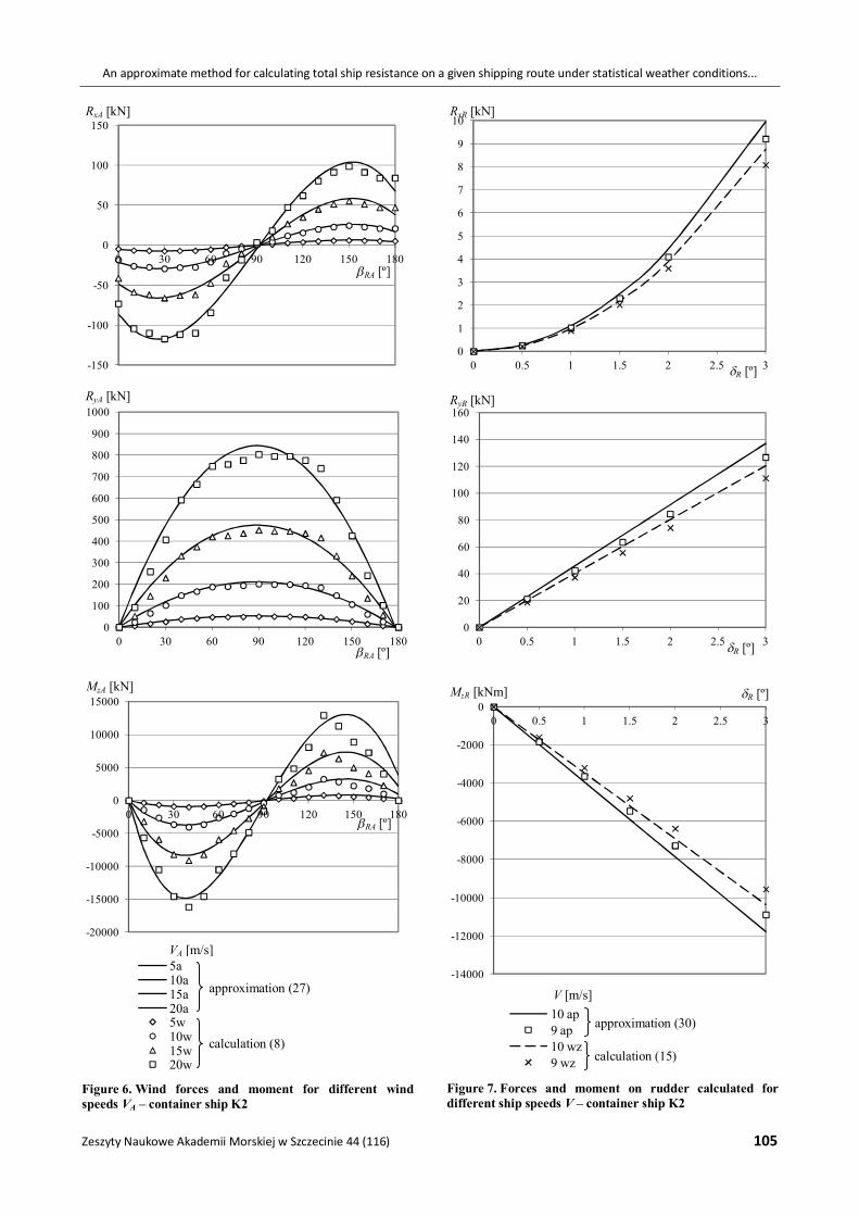
Forces RxA and RyA, as well as MzA, the moment of wind action on the parts of the ship above water, depend on the resistance of the ship’s shape above water (given by coefficients CAx, CAy, and CAm), as well as the surface area of the parts of the ship above water, Sx, and Sy. As a result, the coefficients CAx, CAy, CAm, Sx and Sy are approximated here for selected types of container ships (see Table 1).
The coefficients CAx, CAy and CAm are either em-pirically determined by conducting model tests (Blendermann, 1990; 1991) of the above-water parts of the ship in an aerodynamic tunnel, or by calculations using approximation formulae (Isher-wood, 1973; Vorabjew & Guliev, 1988). These coefficients for a specific type of a ship, such as a container ship, depend on the size of the ship size to a limited degree. Coefficients CAx, CAy and CAm, measured in an aerodynamic tunnel for a container ship (Blendermann, 1990; 1991) have been ap-proximated by a polynomial dependent only on relative wind direction, βRA, (see Figure 2). The following relationships were obtained:
980.0
10181.5
10056.10048.0)(
981.0
101108.101991.0)(
987.0
102900.9105026.2
00991.047676.0)(
2
37
24
2
24
2
3724
R
C
R
C
R
C
RA
RARARAAm
RARARAAy
RARA
RARAAx
(26)
Having developed approximations for coeffi-cients CAx, CAy, CAm, as well as for surfaces Sx and Sy, a set of equations for container ships take the form shown by set (27) below:
3724
2
24
2
3724
2
10181.510056.1
0048.00628.01.184821
101108.1
01991.00628.01.184821
102900.9105026.200991.0
47676.00093.07.46721
RARA
RARAAzA
RA
RARAAyA
RARARA
RAAxA
LVM
VR
VR
(27)
Approximation of forces and moment on plane rudder
In order to work out a simple approximating formula, the following assumptions were made: • From estimates of the drift angle R in the
rudder area (Żelazny, 2005), and from the distri-bution of this angle performed during ship movements along a shipping route, it has been assumed that effective thrust angle (4) is given by:
RR (28)
• Rudder area, AR, and aspect ratio, , were made dependent on basic ship dimensions. Apart ship geometric parameters and rudder an-
gle in equation (18) it is also velocity VR. It has therefore been assumed that the approximating model for velocity VR will take the form of:
VbaVR (29)
Taking into account the approximation of rudder area, AR, and rudder elongation, , final expressions for the forces and moment on rudder are given by the following expressions:

Tadeusz Szelangiewicz, Katarzyna Żelazny
104 Scientific Journals of the Maritime University of Szczecin 44 (116)
R
BzR
R
ByR
RxR
bVac
LTCLM
bVac
LTCR
bVacLTR
2sin)(
1874.20194.06.014.141
2sin)(
1874.20194.06.014.121
)(sin)(1874.20194.0
2
2
22
(30)
where:
25.213.6
21
wc .
Coefficient values a, b, and c for an adopted model for container ships are as follows:
a b λ 5.333 0.329 1.795
Verification of approximation model of total resistance of container ships
Factual verification of the model was carried out by comparing the results of the regression model with calculations made for illustrative ships whose basic parameters are given in Table 2, as well as by tank tests (for relative and absolute error). Results of the model’s verification in the form of relative error values (comparison of values obtained from the regression with the results of exact calculations for illustrative container ships) are shown graphi-cally in Figures 4–7. Table 2. Basic parameters of illustrative ships used to verify the model
Parameter Container ships
K1 K2 K3 Length of the vessel L [m] 140.14 171.94 210.2 Ship breadth B [m] 22.3 25.3 32.24 Draught T [m] 8.25 9.85 10.5 Block coefficient CB [–] 0.641 0.698 0.646 Waterplane coefficient CWP [–] 0.809 0.828 0.807 Displacement [m3] 17290 29900 47250 Ship speed V [m/s] 8.44 9.62 11.37
Figure 4. Resistance of container ship K2 on calm water within drift angle
Figure 5. Resistance (forces and moment) of container ship K1 on calm water with drift angle for different speeds V
0100200300400500600700800900
1000
0 1 2 3 4 5 6 7 8 9 10
approximation (23)
H-M method (Holtrop & Mennen, 1982)publication (Abramowski, 2011)
0
50
100
150
200
250
300
350
400
0 0.5 1 1.5 2 2.5 3
0
50
100
150
200
250
300
350
400
0 0.5 1 1.5 2 2.5 3 3.5
0
5000
10000
15000
20000
25000
0 1 2 3 4
5a6a7a5wz6wz7wz
V [m/s]
Mz [kNm]
RT [kN]
Rx [kN]
[º]
Ry [kN]
[º]
[º]
V [m/s]
approximation (25)
calculation (3)
An approximate method for calculating total ship resistance on a given shipping route under statistical weather conditions...
Zeszyty Naukowe Akademii Morskiej w Szczecinie 44 (116) 105
Figure 6. Wind forces and moment for different wind speeds VA – container ship K2
Figure 7. Forces and moment on rudder calculated for different ship speeds V – container ship K2
-150
-100
-50
0
50
100
150
0 30 60 90 120 150 180
0
100
200
300
400
500
600
700
800
900
1000
0 30 60 90 120 150 180
-20000
-15000
-10000
-5000
0
5000
10000
15000
0 30 60 90 120 150 180
5a10a15a20a5w10w15w20w
0
1
2
3
4
5
6
7
8
9
10
0 0.5 1 1.5 2 2.5 3
0
20
40
60
80
100
120
140
160
0 0.5 1 1.5 2 2.5 3
-14000
-12000
-10000
-8000
-6000
-4000
-2000
00 0.5 1 1.5 2 2.5 3
10 ap9 ap10 wz9 wz
RxA [kN]
RyA [kN]
MzA [kN]
RA [º]
RA [º]
RA [º]
R [º]
R [º]
R [º]
RyR [kN]
MzR [kNm]
V [m/s]
RxR [kN]
calculation (15)
approximation (30)
VA [m/s]
approximation (27)
calculation (8)
Tadeusz Szelangiewicz, Katarzyna Żelazny
106 Scientific Journals of the Maritime University of Szczecin 44 (116)
Conclusions • The final form of the formulae approximating
total ship resistance during a cruise on a specific sea route is quite complex. However, the resis-tance components Rx, Ry and the torque Mz, depend on the basic geometric parameters of the ship available at the preliminary design stage –length L, width B, draught T, side height H, displacement , block coefficient CB, and waterplane area coefficient CWP.
• The number of basic geometric parameters used in the approximation formulae developed is sig-nificantly lower than that in other known ap-proximate methods. Therefore, the approxima-tions developed can be easily used at preliminary ship design stages.
• The tests show that the approximation model developed is accurate enough to be used in pre-liminary ship design. Also, a comparison of newly developed approximations of total resis-tance components with other approximations presented in the literature showed the former were more accurate.
• High accuracy of the final parametric model was achieved mainly by using a multiple criteria re-gression. Artificial neural networks were used only to approximate the additional resistance from the waves for which the highest accuracy was achieved.
• The individual components of the total resis-tance calculated with the approximation formu-lae may contain some errors, but ultimately the total resistance estimation error for model ships was no more than several per cent. The greatest relative errors were obtained when approximat-ing the forces and the torque on the plane rud-
der; however, the impact of these components on total ship resistance is negligible.
References 1. ABRAMOWSKI, T. (2011) Elementy multidyscyplinarnej
optymalizacji wskaźników techniczno-ekonomicznych we wstępnym projektowaniu współbieżnym statków transpor-towych. Szczecin: Wydawnictwo Uczelniane Zachodnio-pomorskiego Uniwersytetu Technologicznego w Szczeci-nie.
2. BLENDERMANN, W. (1990, 1991) Manoeuvring Technical Manual. Shiff und Hafen. Heft 3/1990, Heft 4/1991.
3. HIRANO, M. (1980) On the calculation method of ship manoeuvring motion at the initial design phase. Journal of the Society of Naval Architects of Japan. 147.
4. HOLTROP, J. & MENNEN, G.G.J. (1982) An Approximate Power Prediction Method. International Shipbuilding Pro-gress. 29, 335. pp. 166–170.
5. INOUE, S., HIRANO, M., KIJIMA, K. & TAKASHIMA J. (1981) A practical calculation method of ship manoeuvring mo-tion. International Shipbuilding Progress. 28, 325.
6. ISHERWOOD, M.R. (1973) Wind resistance of merchant ships. The Royal Institution of Naval Architects. 115. pp. 327–338.
7. SZELANGIEWICZ, T. & ŻELAZNY, K. (2006) Calculation of the Mean Long-Term Service Speed of Transport Ship. Part I: Resistance of Ship Sailing on Regular Shipping Route in Real Weather Conditions. Polish Maritime Rese-arch. 4(50), 13. pp. 23–31.
8. VORABJEW, Y.L. & GULIEV, Y.M. (1988) Application of aerodynamics test results in ships and floating structures at sea problems. SMSSH’88, The Proceedings of the 17th Session, Varna, Vol. 1, 17–22 October 1988, pp. 32-1–32-7.
9. ŻELAZNY, K. (2005) Numeryczne prognozowanie średniej długoterminowej prędkości eksploatacyjnej statku trans-portowego. Rozprawa doktorska. Politechnika Szczecińska, Szczecin.
10. ŻELAZNY, K. (2015) A method for determination of service speed useful in the preliminary design of cargo vessels un-der statistical weather conditions occurring on shipping route. Szczecin: Publishing House of West Pomeranian University of Technology in Szczecin.