An approach for reducing adjacent element
10
1752 IEEE TRANSACTIONS ON ULTRASONICS, FERROELECTRICS, AND FREQUENCY CONTROL, VOL. 50, NO. 12, DECEMBER 2003 An Approach for Reducing Adjacent Element Crosstalk in Ultrasound Arrays Shiwei Zhou, Gregory L. Wojcik, Member, IEEE, and John A. Hossack, Senior Member, IEEE Undesired nmu*tic oulput hm Ajncent ~l~~~~~ - deln?& and ouq,ut fmm Central -It~c~d rmplihrclesiwnl Abstract-A method is presented for active cancellation of crosstalk effects in ultrasonic arrays. The approach makes use of the programmable transmitter waveform generators that are now being used with growing prevalence in diagnos- tic ultrasound systems. The array's transmit mode transfer Wrnl acoustic FJoment function is represented by a transfer function matrix. Eie- ments of this matrix are determined by exciting a single, central element with a wideband waveform and determin- ing the resulting pressure output from the central element and adjacent elements. The desired output then is defined (e.g., finite output from a single, central element) and zero output from all other elements. The transfer function ma- trix equation can be solved to determine the required ex- citation functions on both the central array element and its neighbors. These excitation functions will result in re- > Xlechanical closs talk behr-wn clementm ./ duced evidence of crosstalk on the output signals. There- fore, the singleelement, angular-response function is im- Adjacent Ccnhd Adjnmt proved. Using superposition, the approach can he extended to beamformed array excitation. A variety of theoretical and experimental results are shown. The method also can he used in the receive mode hut with a less satisfactory soiu- tion. A transmitting mode experiment based on a prototype uuuuu Element#l Element Element #2 "bray elements sitling on a mrehanifd support (hncker) - not shown Fig. 1. Schematic of interelement crosstalk. ~ fiveelement transducer has provided results indicating that sidelohes in the angular response can he reduced using this technique. I. INTRODUCTION LTRASONIC phased arrays displaced mechanically U scanned diagnostic ultrasound systems many years ago. In these systems, ultrasonic beams are synthesized in both transmit and receive mode to produce high- quality, diagnostically useful images. However, interele- ment crosstalk (or cross coupling) causes degradation of singleelement, angular response. The main lobe of the singleelement response is narrowed and peaks/nulls may be observed at angles corresponding to construc- tive/destructive interference of waves emanating from the array surface due to wave energy propagating outward from the element under consideration. Crosstalk may be separated into acoustic and electrical cross-coupling functions. Electrical crosstalk is controlled by carefully shielding individual array element cables and the array interconnect structure. Electrical crosstalk usu- ally can be limited to approximately -35 dB in a well de- signed array [l]. Notice that electrical crosstalk and acous- tic crosstalk result in different array beamforming arti- facts. Electrical crosstalk is practically instantaneous and, hence, is associated with in-phase effective widening of in- Manuscript received March 24, 2003; accepted June 23, 2003. The authors are with the Biomedical Engineering Department. University of Virginia, Charlottesviile, VA 22908-0759 (+mal: hossack0virginmedu). dividual array elements. This results in a more directional array element and, therefore, may result in a stronger than expected zero steer (broadside) acoustic beam intensity. Acoustic crosstalk is associated with relatively slow acoustic wave propagation between successive array el- ements. Fig. l illustrates schematically the desired out- put energy from a central array element and the de- layed and attenuated outputs from immediately neighbor- ing elements resulting from acoustic crosstalk. This phe- nomenon has heen investigated by many researchers over the years for conventional PZT-based transducers [2]-[6], PZT-epoxy 1:3 composite transducer arrays [7]-[9], and sil- icon micromachined transducers [10]-(13]. Cross coupling in 1:3 piezc-composites and silicon micromachined trans- ducers are generally higher due to lack of isolation cut between the elements and the continuous solid acoustic path between elements. This is particularly true in silicon- based transducers in which the silicon substrate provides a very low-loss acoustic path. A common theme in work on minimizing crosstalk is that physical separation, usu- ally via a gas- or vacuum-filled slot, is preferred. In some applications the fabrication of a slot is not unduly bur- densome and is accepted practice. Most commonly, these slots are made with semiconductor dicing saws that are capable of kerfs of 25 pm or less and high-aspect ratios- over 10 times deeper than wide. However, even with these kerfs, there is still some residual crosstalk in many cases. Additionally, in 1:3 composite transducers and silicon mi- cromachined transducers, an added dicing step defeats the underlying motivation for using the transducer technol- - 088S-3010/$10.00 @ 2003 IEEE Authorized licensed use limited to: Univ of Calif San Diego. Downloaded on August 17,2010 at 23:24:43 UTC from IEEE Xplore. Restrictions apply.
-
Upload
pieter-van-rooyen -
Category
Documents
-
view
213 -
download
1
description
dividual array elements. This results in a more directional array element and, therefore, may result in a stronger than expected zero steer (broadside) acoustic beam intensity. Acoustic crosstalk is associated with relatively slow acoustic wave propagation between successive array el- ements. Fig. l illustrates schematically the desired out- fiveelement transducer has provided results indicating t h a t sidelohes in t h e angular response can h e reduced using this technique. Wrnl acoustic ~
Transcript of An approach for reducing adjacent element

1752 IEEE TRANSACTIONS ON ULTRASONICS, FERROELECTRICS, AND FREQUENCY CONTROL, VOL. 50, NO. 12, DECEMBER 2003
An Approach for Reducing Adjacent Element Crosstalk in Ultrasound Arrays
Shiwei Zhou, Gregory L. Wojcik, Member, IEEE, and John A. Hossack, Senior Member, IEEE
Undesired nmu*tic oulput hm Ajncent
~l~~~~~ - deln?& and ouq,ut fmm Central -It~c~d rmplihrcle siwnl
Abstract-A method is presented for active cancellation of crosstalk effects in ultrasonic arrays. T h e approach makes use of the programmable t ransmit ter waveform generators t ha t a re now being used with growing prevalence in diagnos- tic ultrasound systems. The array's transmit mode transfer
Wrnl acoustic
FJoment
function is represented by a transfer function matrix. Eie- ments of th i s matrix are determined by exciting a single, central element with a wideband waveform and determin- ing the resulting pressure output from the central element and adjacent elements. The desired output then is defined (e.g., finite output from a single, central element) and zero output from all other elements. The transfer function ma- tr ix equation can be solved t o determine t h e required ex- citation functions on both t h e central a r ray element and its neighbors. These excitation functions will result in re-
> Xlechanical closs talk
behr-wn clementm ./
duced evidence of crosstalk on the output signals. There- fore, the singleelement, angular-response function is im- Adjacent Ccnhd Adjnmt
proved. Using superposition, t he approach can h e extended t o beamformed array excitation. A variety of theoretical and experimental results a re shown. The method also can he used in the receive mode hut with a less satisfactory soiu- tion. A transmitting mode experiment based on a prototype
uuuuu Element#l Element Element #2
"bray elements sitling on a mrehanifd support (hncker) - not shown
Fig. 1. Schematic of interelement crosstalk. ~
fiveelement transducer has provided results indicating tha t sidelohes in the angular response can h e reduced using this technique.
I. INTRODUCTION LTRASONIC phased arrays displaced mechanically U scanned diagnostic ultrasound systems many years
ago. In these systems, ultrasonic beams are synthesized in both transmit and receive mode to produce high- quality, diagnostically useful images. However, interele- ment crosstalk (or cross coupling) causes degradation of singleelement, angular response. The main lobe of the singleelement response is narrowed and peaks/nulls may be observed at angles corresponding to construc- tive/destructive interference of waves emanating from the array surface due to wave energy propagating outward from the element under consideration.
Crosstalk may be separated into acoustic and electrical cross-coupling functions. Electrical crosstalk is controlled by carefully shielding individual array element cables and the array interconnect structure. Electrical crosstalk usu- ally can be limited to approximately -35 dB in a well de- signed array [l]. Notice that electrical crosstalk and acous- tic crosstalk result in different array beamforming arti- facts. Electrical crosstalk is practically instantaneous and, hence, is associated with in-phase effective widening of in-
Manuscript received March 24, 2003; accepted June 23, 2003. The authors are with the Biomedical Engineering Department.
University of Virginia, Charlottesviile, VA 22908-0759 (+mal: hossack0virginmedu).
dividual array elements. This results in a more directional array element and, therefore, may result in a stronger than expected zero steer (broadside) acoustic beam intensity.
Acoustic crosstalk is associated with relatively slow acoustic wave propagation between successive array el- ements. Fig. l illustrates schematically the desired out- put energy from a central array element and the de- layed and attenuated outputs from immediately neighbor- ing elements resulting from acoustic crosstalk. This phe- nomenon has heen investigated by many researchers over the years for conventional PZT-based transducers [2]-[6], PZT-epoxy 1:3 composite transducer arrays [7]-[9], and sil- icon micromachined transducers [10]-(13]. Cross coupling in 1:3 piezc-composites and silicon micromachined trans- ducers are generally higher due to lack of isolation cut between the elements and the continuous solid acoustic path between elements. This is particularly true in silicon- based transducers in which the silicon substrate provides a very low-loss acoustic path. A common theme in work on minimizing crosstalk is that physical separation, usu- ally via a gas- or vacuum-filled slot, is preferred. In some applications the fabrication of a slot is not unduly bur- densome and is accepted practice. Most commonly, these slots are made with semiconductor dicing saws that are capable of kerfs of 25 pm or less and high-aspect ratios- over 10 times deeper than wide. However, even with these kerfs, there is still some residual crosstalk in many cases. Additionally, in 1:3 composite transducers and silicon mi- cromachined transducers, an added dicing step defeats the underlying motivation for using the transducer technol-
-
088S-3010/$10.00 @ 2003 IEEE
Authorized licensed use limited to: Univ of Calif San Diego. Downloaded on August 17,2010 at 23:24:43 UTC from IEEE Xplore. Restrictions apply.

ZHOU et al.: REDUCING ELEMENT CROSSTALK IN ULTRASOUND ARRAYS
ogy. The 1:3 composite transducers already are diced as part of their fabrication process, and a primary motiva- tion for using MEMS silicon-based transducers is to specif- ically avoid time-consuming, intricate processes such as sequential element-by-element dicing. Additionally, dicing to form kerf spaces between elements invariably reduces the robustness of the transducer, resulting in potential for low manufacturing yield and reduced reliability in practi- cal use. Thus, there is interest in new approaches that may supplant the dicing process or may augment the crosstalk reduction obtained by dicing.
The impact of relatively slowly propagating crosstalk related acoustic waves on the diffraction pattern of array elements also bas been investigated widely [4], [14]-[16]. The earliest of these papers likened cross coupling to an effective widening of the array element that resulted in an expected narrowing of the single-element beam pattern. However, more recent work [I61 takes account of the rela- tive phasing of the crosstalkelements and results in a more accurate and complex estimate of the impact of crosstalk on the single element diffraction pattern. The negative im- pact of crosstalk on the diffraction pattern is clear; con- sequently, the need to minimize acoustic crosstalk also is readily evident.
In addition to acoustic crosstalk through a filled kerf or through the backing medium, another significant source of crosstalk is through the matching layer and lens ma- terial. Clearly, crosstalk through the matching layers may be minimized by dicing the matching layer-though this is not always done for a variety of practical reasons. It is not practical to use physical separation in the lens as this forms the fluid impermeable outer surface of the transducer. Tak- ing account of all these design issues, a reasonable upper limit on crosstalk suppression in conventional diced PZT arrays is approximately -35 dB [I].
-PI- -HII HIZ H13 H14 H15 Hl6 -VI- PZ HZI H ~ Z H23 H24 HZ5 HZ6 H z ~ VZ P3 H3i H32 H33 H34 H35 H36 H37 V, P 4 = H4i H42 H43 H44 H45 H46 H47 V, , 4 H51 H52 H53 H54 H55 H56 H57 V5 (1) p6 H61 H6z H63 H64 H65 H66 H67 b
- H ~ I H72 H73 H74 H75 H16 H77-
11. THEORY
This paper describes an electrical stimulation-based ap- proach for canceling out the effects of acoustic crosstalk. In summary, an electrical stimulation function for adjacent elements is developed to cancel out the acoustic output from adjacent elements that would otherwise occur.
Modern diagnostic transducer arrays are operated as phased systems. Each array element in a phased-array system is stimulated by an electrical waveform with spe- cific shape, amplitude, and delay. Historically, these driv- ing waveforms were simple in form-impulses, steps, or square wave bursts. However, the current state of the art in diagnostic ultrasound involves the use of waveforms with programmed shape in which the harmonic components are minimized. The major motivation behind the widespread use of reduced transmitted harmonic signals is for har- monic imaging modes of operation. In the context of this paper, the significance of these developments is that, if the capability for providing programmed, shaped wav.4- forms exists on an ultrasound machine, the machine has the capability-at least in pr inc ip le to take advantage
Authorized licensed use limited to: Univ of Calif San Diego. Downloaded on August 17,2010 at 23:24:43 UTC from IEEE Xplore. Restrictions apply.

1754 IEEE TRANSACTIONS ON ULTRASONICS, FERROELE
-PI- -HII HIZ HI3 0 0 0 0 - -VI- Pz HZI Hzz H23 H24 0 0 0 Vz P3 H ~ I H32 H33 H34 H35 0 0 V, P4 = 0 H42 H43 H44 H45 H ~ G 0 V, . p5 0 0 H53 H54 H55 HSG H57 v5 (2) PG 0 0 0 E64 H G ~ H66 H67 % -p7. . 0 0 0 0 H75 f f x H77- -v7.
PI
P4 P3 p 2 ~ ~ ~ ~
P5 ’”ad= P7 Fig. 2. Seven-element array with seven field points right above array surface.
where H [abbreviated from H ( f ) ] is the transfer function matrix relating input voltages, V,, to the output pressures, P, .
The example shown here is for a seven-element array, but this can be expanded as required. Fig. 2 illustrates this configuration. We will consider the ideal case in which an impulse is applied to the center element. (In this paper the term center element will be used to denote the desired, driven element. The term adjacent element will be applied to the nearest neighboring element on one side. Generally, we assume that there is symmetry around the center el- ement and, therefore, the adjacent element could equally be on one side or the other.) V, is an impulse (i.e., uniform amplitude for all frequencies in the frequency domain). V, to V3 and V5 to V7 are zero. P4 is the direct output from the fourth element. However, because some of the nondi- agonal terms in the H matrix are nonzero, there will be finite output from the other elements (i.e., some of PI, Pz, P3, 5 , PG, and P7 will be nonzero). Once the matrix His defined, we can solve the matrix problem to find values for VI to V7 such that we do actually get the desired output (i.e., PI to P3 = 0, P4 = ideal impulse response of the fourth element and P5 to P7 = 0).
In fact, crosstalk is only significant on a few neighbor- ing elements. In the c s e below we assume that crosstalk is limited to two elements on each side of the element be- ing excited. However, this is not a limitation here; we can consider the full matrix encompassing all crosstalk terms if required. The matrix becomes a banded matrix with bandwidth 5. All other values of H are 0. This simplifies the characterization of the H matrix and allows for more efficient matrix solution.
Notice that there is significant symmetry in the ma- trix. We typically assume that crosstalk from array ele- ment three to array element four is the same as from ar- ray element four to array element five, and so on. There might be some irregular behavior at the ends of the ar- ray due to different boundary conditions. However, even in this case the change in crosstalk is probably modest as it is common practice to have one or two “test” elements that are used during manufacture to ensure alignment of the saw blade with the designed kerf location before dicing the “real” elements. For the matrix shown in (Z), we only need to measure the crosstalk function of the two adja- cent elements resulting from impulse excitation of a cen-
Authorized licensed use limited to: Univ of Calif San Diego. Downloaded on August 17,2010 at 23:24:43 UTC from IEEE Xplore. Restrictions apply.

PI - P24 P3 - P4 +
P5 -’ P6 P7 -’
1755
- VI - v2 - v3 - v4 points. In this case we have more defined “output” condi- tions than defined “inputs”. Thus, the problem is overcon- strained and requires a pseudwinverse solution. This will find a best-fitting solution in a least-squares sense. The Matlab “pinv” command implements this operation in an efficient and easy-to-use manner. This command uses sin- gular value decomposition to find the pseudo-inverse:
-Pi Hi2 0 0 9 Hzi Hzz 0 0 P3 H31 H32 H33 0 P 4 = 0 H42 H43 0 p5 0 H52 H53 H54
p6 0 0 H63 H64 -P7- 0 0 H73 H74-
[ ] (4)
TABLE I ACOUSTIC PROPERTIES FOR THE FEA MODEL.
Material Impedance (MRayl) PZT 34.2
Matching material 3.92 ~
Backing material 2.15 Lens 1.5
possible approach would be to assume that the crosstalk is equivalent to “interference”, or ‘gamming”, in the lan- guage of adaptive beamforming and calculate filters that place a null at the direction of the “jamming”. Because the array’s sidelobe response is fixed internally, it should be possible to use a relatively simple adaptive beamform- ing approach because a significant amount of apriori and time-independent information about the origin of the side- lobe should be accessible. A discussion of basic, a i d nioie advanced, forms of adaptive beamforming can be found in 1181. In this paper we concern ourselves with crosstalk cancellation in the transmit path as a more complete and satisfying solution to the problem is available. Addition- ally, since the two-way heam pattern can be approximated by the product of the transmit and receive beam pattern, an elimination of the sidelobes caused by crosstalk in the transmit heam pattern alone probably will provide suf- ficient suppression to enable satisfactory two-way beam response.
111. SIMULATION RESULTS
Finite element analysis software has evolved to the point that there is considerable confidence in the results obtained using it. The limitations in accuracy when compared to experimental results primarily result from inexact knowl- edge of actual component geometry and component mate- rial parameters. Material parameters are very challenging to characterize fully in terms of all the cross terms in the elasticity matrix and all the attenuation terms. Addition- ally, bond lines can be difficult to model with high accu- racy. All of these factors increase the difficulty in obtaining good experimental data if one is relying on an FEA model to determine the required compensation signals. There- fore, in this paper we present the bulk of our results using FEA simulation data. In addition, we present some limited experimental data obtained using a prototype array.
A . Tkansmitting Mode
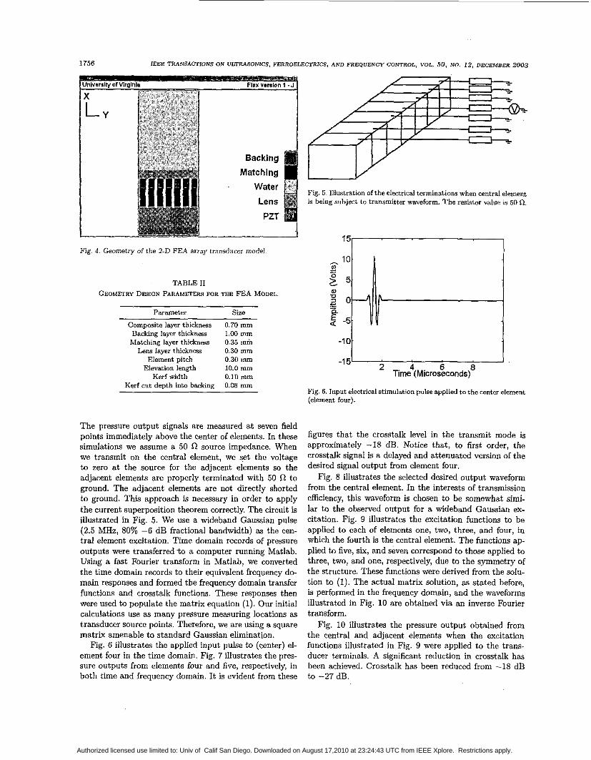
A 2-D ultrasound transducer array model was modeled using PZFlex. The model is illustrated in Fig. 4. The ac- tual FEA model takes advantage of the symmetry plane and, hence, only the FEA models one half of the device illustrated. Important acoustic properties and geometry design parameters are described in the Tables I and 11.
Seven elements are indexed from one to seven simulated in this model, in which four is the center element (Fig. 4).
Authorized licensed use limited to: Univ of Calif San Diego. Downloaded on August 17,2010 at 23:24:43 UTC from IEEE Xplore. Restrictions apply.
1756 IEEE TRANSACTIONS ON ULTRASONICS. FERROELECI'RICS, AND FREQUENCY CONTROL, VOL. 50, NO. 12, DECEMBER 2003
Fig. 4. Geometry of the 2-D FEA array transducer model
TABLE I1 GEOMETRY DESIGN PARAMETERS FOR THE FEA MODEL.
Parameter Size
Composite layer thickness 0.70 mm Backing layer thicknas 1.00 mm Matching layer thicknm 0.35 m& Lens layer thickness 0.30 mm
Element pitch 0.30 mm Elevation length 10.0 mm Kerf width 0.10 mm
0.08 mm Kerf cut depth into backing
The pressure output signals are measured at seven field points immediately above the center of elements. In these simulations we assume a 50 R source impedance. When we transmit on the central element, we set the voltage to zero at the source for the adjacent elements so the adjacent elements are properly terminated with 50 R to ground. The adjacent elements are not directly shorted to ground. This approach is necessary in order to apply the current superposition theorem correctly. The circuit is illustrated in Fig. 5. We use a wideband Gaussian pulse (2.5 MHz, 80% -6 dB fractional bandwidth) as the cen- tral element excitation. Time domain records of pressure outputs were transferred t o a computer running Matlab. Using a fast Fourier transform in Matlab, we converted the time domain records to their equivalent frequency d e main responses and formed the frequency domain transfer functions and crosstalk functions. These responses then were used to populate the matrix equation (1). Our initial calculations use as many pressure measuring locations as transducer source points. Therefore, we are using a square matrix amenable to standard Gaussian elimination.
Fig. 6 illustrates the applied input pulse to (center) el- ement four in the time domain. Fig. 7 illustrates the pres- sure outputs from elements four and five, respectively, in both time and frequency domain. It is evident from these
Fig. 5. Illustration of the electrical terminations when central element is being subject to transmitter waveform. The resistor value is 50 R.
15' 'i" , , , 1 a 0 n - g -5
-10
-1 5 2 4 . 6 8 Time (Microseconds)
Fig. 6. Input electrical stimulation pulse applied to the center element (element four).
figures that the crosstalk level in the transmit mode is approximately -18 dB. Notice that, to first order, the crosstalk signal is a delayed and attenuated version of the desired signal output from element four.
Fig. 8 illustrates the selected desired output waveform from the central element. In the interests of transmission efficiency, this waveform is chosen to be somewhat simi- lar to the observed output for a wideband Gaussian ex- citation. Fig. 9 illustrates the excitation functions to be applied to each of elements one, two, three, and four, in which the fourth is the central element. The functions ap- plied to five, six, and seven correspond to those applied to three, two, and one, respectively, due to the symmetry of the structure. These functions were derived from the solu- tion to (1). The actual matrix solution, as stated before, is performed in the frequency domain, and the waveforms illustrated in Fig. 10 are obtained via an inverse Fourier transform.
Fig. 10 illustrates the pressure output obtained from the central and adjacent elements when the excitation functions illustrated in Fig. 9 were applied to the trans- ducer terminals. A significant reduction in crosstalk has been achieved. Crosstalk has been reduced from -18 dB to -27 dB.
Authorized licensed use limited to: Univ of Calif San Diego. Downloaded on August 17,2010 at 23:24:43 UTC from IEEE Xplore. Restrictions apply.

ZHDU et al.: REDUCING ELEMENT CROSSTALK IN ULTRASOUND ARRAYS
1-
2-
1757
Fig. 7. Pressure outputs (obtained via FEA) from center element (four) and adjacent element (five), in time (left) and frequency (right) domain.
I 4 . 6 8 10
Time (Microseconds) -2b 2
Fig. 8. Deired output pressure waveform from the central element.
4
5
7. I 0 2 4 . 6 8 10
Time (Microseconds)
Fig. 9. Excitation functions to be applied on each of element, one to seven, where four is the center element (arbitrary amplitude units).
The crosstalk reduction process then was repeated us- ing approximately twice as many pressure field sample points-ne in front of the center of each element and one in additional point midway between these sample points (i.e., above the intermediate kerf region). In this case there are 13 field points for the seven transducer elements. In fact, due to symmetry, only seven field points and four transducer elements were analyzed. Again, a broadband Gaussian pulse, identical to that used above, was used as the desired central element output. Following the process described in the above theory section, the required excita- tion functions were obtained after finding a pseudo-inverse solution to the matrix equation (3). The actual waveforms calculated using this second approach, and the consequent reduction in crosstalk, are so similar to those reported above for the square matrix case (1) that they are not plotted. This suggests that, at least for this example, the simple square matrix approach is sufficient.
B. Single-Element Angular Response
Ultimately, the major impact of crosstalk is the degra- dation of the single-element, angular response. Generally, beamforming starts from the assumption that individual elements behave as point or line sources with an approxi- mately uniform response as a function of angle. Typically, for example, a half wavelength element has an angular re- sponse that is reduced by no more than -6 dB out to the limits of expected use (Le., 45 degrees). However, crosstalk may cause main lobe narrowing (due to wider effective aperture) and sidelobes due to constructive/destructive in- terference due to waves propagating along the array sur- face and leaking into the fluid medium. Therefore, a single- element heamplot is a valuable indicator of crosstalk per- formance. Fig. 11 illustrates the theoretical single-element, angular transmit response using Selfridge’s equation [19]. Fig. 11 also illustrates the single-element response ob- tained (using FEA) for both the case without crosstalk cancellation and with crosstalk cancellation. The improve- ment in single element angular response is readily evident.
Authorized licensed use limited to: Univ of Calif San Diego. Downloaded on August 17,2010 at 23:24:43 UTC from IEEE Xplore. Restrictions apply.

1758 IEEE TRANSACTIONS ON ULTRASONICS, FERROELECTRICS, AND FREQUENCY CONTROL, VOL. 50, NO. 12, DECEMBER 2003
5 2x 10
....... - U)
e - E < -1-
4 . 6 8 -2
Time (Microseconds) Frequency (MHz)
Fig. 10. The pressure outputs from center and adjacent element (obtained via FEA) after applying the compensation signals, in time and frequency domain. Time domain, left; frequency domain;right.
i - Void kerf filler - ideal ’; -4 j ....... No compensation ’;
~ 1 I ----- With compensation I 1 , 0 20 40 Degrees -40 -20
-5‘ ’
Fig. 11. Theoretical angular response (&t 2.5 MHz) and FEA simulb tion of the angular response for both the no compensation and with compensation case.
IV. EXPERIMENTAL RESULTS
A prototype transducer array was fabricated for testing the crosstalk cancellation method (Fig. 12). The trans- ducer active element was made of PZT-SH type piezoelec- tric ceramic (HD3203, CTS Ceramics, Albuquerque, NM). The elements are 16 mm long (elevation) and 1.64 mm thick. Five elements were diced to form elements with a 0.6 mm center-to-center pitch. The kerf was 90 pm wide and filled with an unfilled, nonconductive epoxy. A 1-mm thick glass reinforced plastic printed circuit board (PCB) was used as the substrate and conductive silver-epoxy used to bond the transducer elements to the substrate. The elec- trical contact from the lower surface of the PZT to the PCB was used as the electrical signal path. The kerfs were cut 0.2 mm into the PCB board to assure the electrical isolation between neighbor elements. On the top of the transducer, a thin, gold-plated polyester layer was used as the “ground” return. Critical acoustic properties and geometry parameters are described in Tables 111 and N.
Ground Layer,
Water Region
PCB Board
Fig. 12. Experimental trsnsducer configuration.
TABLE 111 ACOUSTIC PROPERTIES FOR THE EXPERIMENTAL MODEL
Material Impedance (MRayl)
PZT 34.20 Epoxy 3.05
PCB board 6.65
The acoustic properties for all component materials were obtained from manufacturers’ datasheets, or mea- sured experimentally. All critical transducer dimensions were measured. We then simulated the device using PZFlex and used a 1-MHz, 50% -6 dB fractional band- width Gaussian pulse as the excitation applied to the cen- ter element. We obtained the direct output from the cen- tral element and from the nearest two neighbors and p o p ulated the transfer function matrix (1). We then solved the equation and obtained the required excitation func- tions for the array. We attempted to measure the outputs from the individual elements by placing a GL-0085 hy- drophone (Onda Corp./Specialty Engineering Associates, Sunnyvale, CA) adjacent to the elements. However, this measurement did not provide useful results. We believe that we cannot get close enough to the transducer element
Authorized licensed use limited to: Univ of Calif San Diego. Downloaded on August 17,2010 at 23:24:43 UTC from IEEE Xplore. Restrictions apply.
d.: REDUOIN(: ELEMENT CROSSTALK IN ULTRASOUND ARFAYS 1759 ZHOU et
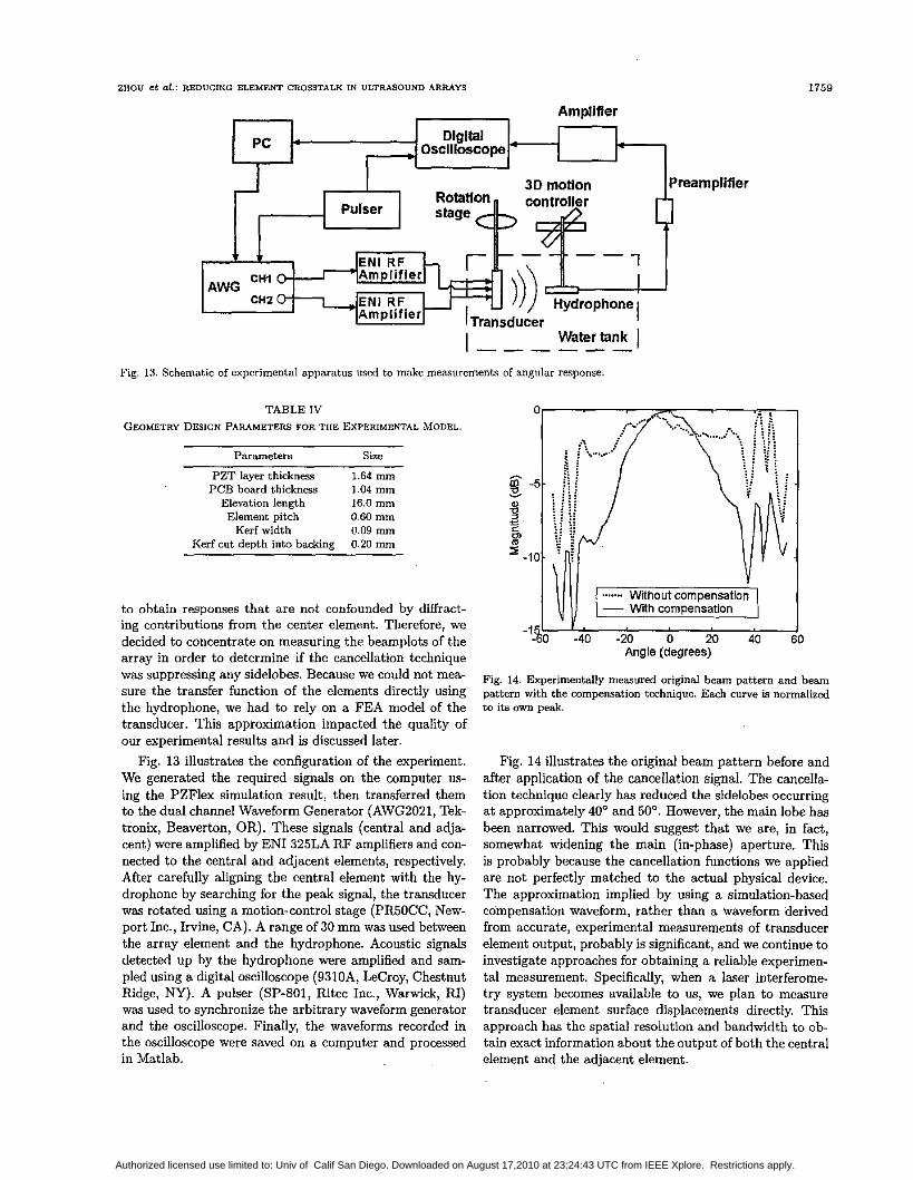
Fig. 13.
Amplifler
Watertank I Schematic of experimental apparatus used to make measurements of angular response.
TABLE IV GEOMETRY DESIGN PARAMETERS FOR THE EXPERIMENTAL MODEL.
Parameters Size ~ ~ ~~
PZT layer thickness 1.64 mm PCB board thickness 1.04 mm
Elevation length 16.0 mm Element pitch 0.60 mm
Kerf width 0.09 mm 0.20 mm Kerf cut depth into backing
to obtain responses that are not confounded by diffract- ing contributions from the center element. Therefore, we decided to concentrate on measuring the beamplots of the array in order to determine if the cancellation technique was suppressing any sidelobes. Because we could not mea- sure the transfer function of the elements directly using the hydrophone, we had to rely on a FEA model of the transducer. This approximation impacted the quality of our experimental results and is discussed later.
Fig. 13 illustrates the configuration of the experiment. We generated the required signals on the computer US-
ing the PZFlex simulation result, then transferred them to the dual channel Waveform Generator (AWG2021, Tek- tronix, Beaverton, OR). These signals (central and adja- cent) were amplified by EN1 325LA FW amplifiers and con- nected to the central and adjacent elements, respectively. After carefully aligning the central element with the hy- drophone by searching for the peak signal, the transducer was rotated using a motion-control stage (PFSOCC, New- port Inc., Irvine, CA). A range of 30 mm was used between the array element and the hydrophone. Acoustic signals detected up by the hydrophone were amplified and sam- pled using a digital oscilloscope (9310A, LeCroy, Chestnut Ridge, NY). A pulser (SP-801, Ritec Inc., Warwick, RI) was used to synchronize the arbitrary waveform generator and the oscilloscope. Finally, the waveforms recorded in the oscilloscope were saved on a computer and processed in Matlab.
Preamplifier 4
Angle (degrees)
Fig. 14. Experimentally measured original beam pattern and beam pattern with the compensation technique. Each curve is normalized to its own p d .
Fig. 14 illustrates the original beam pattern before and after application of the cancellation signal. The cancella- tion technique clearly has reduced the sidelobes occurring at approximately 40' and 50". However, the main lobe has been narrowed. This would suggest that we are, in fact, somewhat widening the main (in-phase) aperture. This is probably because the cancellation functions we applied are not perfectly matched to the actual physical device. The approximation implied by using a simulation-based compensation waveform, rather than a waveform derived from accurate, experimental measurements of transducer element output, probably is significant, and we continue to investigate approaches for obtaining a reliable experimen- tal measurement. Specifically, when a laser interferome- try system becomes available to us, we plan to measure transducer element surface displacements directly. This approach has the spatial resolution and bandwidth to ob- tain exact information about the output of both the central element and the adjacent element.
Authorized licensed use limited to: Univ of Calif San Diego. Downloaded on August 17,2010 at 23:24:43 UTC from IEEE Xplore. Restrictions apply.

1760 IEEE TRANSACTIONS ON ULTRASONICS, FERROELECTRICS, AND FREQUENCY CONTROL, VOL. 50, NO. 12, DECEMBER 2003
V. DISCUSSION
In ultrasound systems in which the capability to pro- gram arbitrary-shaped transmitter voltage waveforms on an element-by-element basis, the approach described above can, in principle, yield a useful improvement with no added hardware complexity. The method and results in themselves may not justify the added expense of the pro- grammable waveforms; but, if they are being justified for other purposes (such as harmonic imaging), then a useful improvement may be obtained at an economic cost (i.e., the added engineering investment required to enable the waveforms proposed here). It is recognized that the soft- ware development required to implement these modified waveforms on a channel-by-channel hasis may be nontriv- ial.
The approach may b e applied in a relatively straight- forward manner for the transmit mode. Once the element transfer function and interelement crosstalk functions are known, a matrix equation solution method may he a p plied to determine the correct crosstalk reduction func- tions. However, in the receive mode, it is very much more problematic to try to remove the effects of cancellation due to the compounded nature of the received data resulting from the desired element response and the crosstalk com- ponent added from adjacent elements. A signal subtraction approach could be used, but this inevitably would reduce SNR.
When the approach was investigated using a FEA model, very satisfactory results were obtained. Crosstalk was reduced from -18 dB to -27 dB. We then attempted to perform an experimental verification of the technique. Unfortunately, this experiment was very difficult to per- form with the resolution that is required. We did demon- strate a significant reduction in sidelobe activity. But it is clear from the main lobe width reduction that we did not obtain a response corresponding to a single, well iso- lated, element. We are investigating possible improvements to our experiment by, for example, wing a better charac- terized array. We believe that, with sufficient investment in transducer characterization, results similar to those demonstrated using FEA can be obtained. It is widely ac- cepted that FEA provides very realistic results when the materials and geometry are exceptionally well character- ized. It follows from this that, eventually, reductions such as we demonstrate here using FEA (a 9 dB reduction) are practically attainable.
Further work is required to test the ability of the method to improve the performance of very high crosstalk arrays such as silicon MEMS-based transducers. In these devices, and many others with highly acoustic crosstalk, there is a significant transverse wave component to the crosstalk. Because the method here is based around a 1-D consideration of each element's behavior and crosstalk, it may be expected that the method cannot as fully oom- pensate for transverse wave related crosstalk as, for ex- ample, a 1-D acoustic wave propagating into the backing, across the kerf base, and up the backing support into an
adjacent element. There are few effective approaches for reducing crosstalk in silicon-based transducers (or contin- uous 1:3 composite array structures) other than forming deep trenches by etching or dicing [ll]. In these situations, even a modest improvement offered by the cancellation technique discussed here may be very worthwhile.
In this paper we have not directly addressed the is- sue of stability of the crosstalk cancellation method. How- ever, based on the somewhat disappointing experimental results, it is clear that the method is dependent on accurate characterization of the transducer materials and geome- try. However, with increasing quality control and better materials characterization, the impact of this limitation is expected to lessen over time.
The study presented here has focused on crosstalk in 1- D arrays, and our modeling used a 2-D FEA mesh. Clearly, the approach can be extended to use for 2-D arrays and use 3-D FEA. In fact, since 2-D arrays are inherently more intricate than 1-D arrays, the crosstalk problems may be more serious; therefore, they probably have a greater requirement for some form of crosstalk reduction tech- nique. However, the requirement for programmable wave- form generators for each of N2 elements rather than simply N (as in a 1-D array), may be prohibitively expensive.
VI. CONCLUSIONS
In this paper, we analyzed the crosstalk in ultrasound transducer arrays using a transfer function matrix ap- proach. By defining the direct and cross-coupling terms in the matrix, it is possible to solve the matrix equa- tion to obtain required excitation functions for central and adjacent elements so that, within practical limita- tions, there is finite output from the central element alone. The method has been shown to be effective in FEA sim- ulations. However, our initial experimental data suggest that either very careful experimental characterization or, alternatively, very meticulous modeling is required in or- der to obtain the desired effects experimentally. The prc- grammable waveform generators found in some modern ul- trasound machines may enable the implementation of the techniques discussed here a t minimal cost.
ACKNOWLEDGMENTS
This work was partially funded by the Whitaker Foun- dation. Thanks also are due to Paul Reynolds, Ph.D., at Weidlinger Associates Inc. for advice on the use of the PZFlex FEA code. We also thank the anonymous review- ers for their advice.
REFERENCES
[l] C. Desilets, "Medical ultrmonic transducer array design and a p plications," presented at Proc. IEEE Ultmson. Symp.. 1997.
Authorized licensed use limited to: Univ of Calif San Diego. Downloaded on August 17,2010 at 23:24:43 UTC from IEEE Xplore. Restrictions apply.

ZHOU et Of.: REDUCING ELEMENT CROSSTALK IN ULTRASOUND ARRAYS
[2] G. S. Kino and R. Baer, “Theory for crosscoupling,” in Pmc. IEEE U f t m w n . Symp., 1983, pp. 1013-1019.
(31 J. D. Larson, “Non-ideal radiators in phased array transduc- ers,” in Pmc. IEEE Ultmson. Symp., 1981, pp. 673-684.
[4] J. F. Dim, “An experimental investigation of the cross coupling between elements of an acoustic imaging array transducer,” Ul-
1761
[la] B. Widrow and S. Stearns, Adaptive S i p n l Processing. Upper Saddle River, NJ: Prentice.Hal1, 1985, pp. 368-455.
1191 A. R. Selfridge, G. S. Kino, and B. T. Khuri-Yakub, “A the. ory for the radiation pattern of a narrow-strip acoustic trans- ducer,” Appl. Phys. Lett., vol. 37, pp. 35-36, 1980.
tmson. Imog., vol. 4, pp. 44-55, 1982. J. F. Guess, C. G. Oakley, S. J. Douglas, and R. D. Morgan, “Crosstalk uaths in array transducers,” in Pmc. IEEE Ultmson.
[5]
Symp., 1995, pp. 1279-i282. [6] R. Johnson, “Crosscoupling analysis for wideband arrays,” Pme.
IEEE Ultmson. Symp., 1995, pp. 1349-1352. [7] G. Wojcik, D. K. Vaughn, V. Murray, and J. Mould, “Time do-
main modeling of composite arrays for underwater imaging,” in Pmc. IEEE Ultmson. Symp., 1994, p p . 1027-1032. D. Certon, N. Felix, L. Pascal, T. H. Hue, F. Patat, and M. L e t h i q , “Evaluation of laser probe performances for measuring cross coupling in 1-3 pia-composite arrays,” in Pm. IEEE Lntmson. Symp., 1999, pp. 1091-1094.
[Q] D. Certon, N. Felix, E. Lacaze, F. Teston, and F. Patat, “Inves- tigation of cross-coupling in 1-3 piemcomposite arrays,“ IEEE 1Sans. Ultrason., Fevoelect., h q . Contr., vol. 48, pp. 85-92, 2001.
[lo] G. Wojcik, J. Mould, P. Reynolds, A. Fitzgerald, P. Wagmi-, and I. Ladabaum, “Timedomain models of MUT array crosstalk in silicon substrates,” in Pme. IEEE U l t m o n . Symp., 2000, pp. 909-914.
(111 X. C. Jin, 0. Oralkan, F. L. Degertekin, and B. T. Khuri-Yakub, “Characterization of onedimensional capacitive micromachined ultrasonic immersion transducer arrays,” IEEE %ns. Ultm- son., Femxfect., h. Contr., vol. 48, pp. 75&759, 2W1.
[12] M. Kaltenbacher, H. Lands, K. Niederer, and R. Lerch, “3D simulation of controlled micromachined capacitive ultrasound transducers,” in Pmc. IEEE Ultmson. Symp., 1999, pp. 1155- 1158.
1131 J.-H. MO, J . Fowlkes, A. L. Robinson, and F. Carson, “Crosstalk reduction with B micromachined diaphragm structure for inte grated ultrasound transducer arrays,” IEEE 75ons. Ultmson., Femeleet., Prep. Contr., vol. 39, pp. 48-53. 1992.
[14] N. Felix, E. Lacaze, M. Lethiecq, and F. Patat, “Experimental investigation of crosscoupling and its influence on the elemen- tary radiation pattern in 1D ultrasound arrays,” in Proc. IEEE Ultmson. Symp., 1999, pp. 1053-1056.
1151 N. Lambexti. “Radiation oattern distortion cavsed bv the in-
(81
. > terelement coupling in linear array transducers,” in Pmc. IEEE Ultmson. Symp., 1999, pp. 1071-1075.
[16] J. Ass& and C. Bruneel, “Radiation from finite phased and fo- cused linear array including interaction,” J. Acoust. Soc. Amer., vol. 101, pp. 1859-1867, 1997.
1171 G. L. Wojcik, D. K. Vaughan, N. Abboud. and J. Mould, “Elec- tromechanical modeling using explicit time domain finite de- ments,” in Pmc. IEEE Ultmson. Symp., 1993, pp. 1107-1112.
Shiwei Zhou was born in Beijing, China in 1974. He received the B.S. and M.S. degrees in optical-electrical engineering from Beijing In- stitute of Technology, Beijing, China, in 1996 and 1999, respectively. He is currently work- ing towards the Ph.D. degree in medical ultra- sound imaging at the Department of Biomed- ical Engineering of the University of Virginia, Charlottesville, VA. His research interests are ultrasound transducer modeling and design using finite element analysis. applications of digital signal processing techniqies in ultra
sound, and the use of ultrasound with microbubbles for diagnosic and therapeutic applicat.ions.
John A. Hossack (S’9D-M’92-SM’02) was born in Glasgow, Scotland. in 1964. He earned his B.Eng. Hons(1) degree in electrical elec- tronic engineering from Strathclyde Univer- sity, Glasgow, in 1986 and his Ph.D. de. gree in the same department in 1990. From 1990 to 1992, Dr. Hossaek was a post doc- toral researcher in the E. L. Ginzton Labo- ratory of Stanford University working under B. A. Auld’s guidance. His research was on modeling of 0 3 and 1:3 Diemelectric comuw ite transducers. In 1992, he joined Acukn,
Mountain View, CA, initially working on transducer design. During his time at Acuson his interests diversified into beamfarming and 3-D imaging. Dr. Hossack was made a Fellow of Acuson for ‘excellence in technical contribution’ in 1999. In 2000 he joined the Biomedical En- gineering Department at the University of Virginia, Charlottesville, VA .
His current interests are in improved 1 D ultrasound imaging and high bandwidth transducers/signal procesing. Dr. Hossack is amem- ber of the IEEE and serves on both the Administrative Committee and the Technical Program Committee of the Ultrasonics Section. He also is an Associate Editor of the IEEE 7bnsaetions on Ultmsonics, Femeleetrics, and Fkquency Control.
Authorized licensed use limited to: Univ of Calif San Diego. Downloaded on August 17,2010 at 23:24:43 UTC from IEEE Xplore. Restrictions apply.