An analysis of single wire earth return (SWER) system for ...
77
Scholars' Mine Scholars' Mine Masters Theses Student Theses and Dissertations 1972 An analysis of single wire earth return (SWER) system for rural An analysis of single wire earth return (SWER) system for rural electrification electrification Balwinder Singh Samra Follow this and additional works at: https://scholarsmine.mst.edu/masters_theses Part of the Electrical and Computer Engineering Commons Department: Department: Recommended Citation Recommended Citation Samra, Balwinder Singh, "An analysis of single wire earth return (SWER) system for rural electrification" (1972). Masters Theses. 5062. https://scholarsmine.mst.edu/masters_theses/5062 This thesis is brought to you by Scholars' Mine, a service of the Missouri S&T Library and Learning Resources. This work is protected by U. S. Copyright Law. Unauthorized use including reproduction for redistribution requires the permission of the copyright holder. For more information, please contact [email protected].
Transcript of An analysis of single wire earth return (SWER) system for ...

Scholars' Mine Scholars' Mine
Masters Theses Student Theses and Dissertations
1972
An analysis of single wire earth return (SWER) system for rural An analysis of single wire earth return (SWER) system for rural
electrification electrification
Balwinder Singh Samra
Follow this and additional works at: https://scholarsmine.mst.edu/masters_theses
Part of the Electrical and Computer Engineering Commons
Department: Department:
Recommended Citation Recommended Citation Samra, Balwinder Singh, "An analysis of single wire earth return (SWER) system for rural electrification" (1972). Masters Theses. 5062. https://scholarsmine.mst.edu/masters_theses/5062
This thesis is brought to you by Scholars' Mine, a service of the Missouri S&T Library and Learning Resources. This work is protected by U. S. Copyright Law. Unauthorized use including reproduction for redistribution requires the permission of the copyright holder. For more information, please contact [email protected].

f I
f
AN ANALYSIS OF SINGLE WIRE EARTH RETURN(SWER) SYSTEM
FOR RURAL ELECTRIFICATION
BY
BALWINDER SINGH SAMRA, 1945-
A THESIS
Presented to the Faculty of the Graduate School of the
UNIVERSITY OF MISSOURI-ROLLA
In Partial Fulfillment of the Requirements for the Degree
MASTER OF SCIENCE IN ELECTRICAL ENGINEERING
1972
Approved by
T272fJ 76 pages c. I

ii
ABSTRACT
The primary objective of this investigation ~~as to determine the
general applicability of Single Phase Earth Return(SWER) system for
rural electrification where the load density is low, for example
electrification of farms and small villages in emerging nations. The
limitations of SWER system of distribution are many and it is neces
sary to make judicious use of such transmission.
In this investigation the construction costs of transmission and
distribution by SWER system is compared with single phase and three
phase systems for loads of 25KVA and 50KVA. Phase converters are
required to operate a three phase motor on a single phase supply.
Three different types of static phase converters are discussed and
their merits and costs are compared. Four different types of grounding
systems are discussed in this study. The heating of earth electrodes
due to continuous ground current flowing through the electrodes is
investigated. Co-ordination of SWER systems with telecommunication
lines is discussed in detail. Dan~er to humans and animals due to
potential gradient at the surface of the earth in the vicinity of the
grounding system caused by continuous ground current is also investi
gated in this study.

iii
ACKNOWLEDGr~ENT
The author of this thesis is deeply indebted to Dr. J. D. Morgan,
who served as research advisor, for his help, guidance and encourage
ment during the course of this investigation.
The moral encouragement and valuable suggestions of Professor
George McPherson, Jr., are highly appreciated. The author would like
to thank Dr. J. M. Amos for his help and service as committee member.
Thanks go to t1rs. Carol Rodman for typing the manuscript.

iv
TABLE OF CONTENTS
Page
ABSTRACT • ••••••••••••••••••••••••••••••••••••••••••••••••••••••••••• i i
ACKNOWLEDGMENT • •••••••••••••••••••••••••••••••••••••••••••••••••••• iii
LIST OF FIGURES ••••••.••••..••••.•.•.•.•.••..•.•..•.•.••.•••••..•••• vi
LIST OF TABLES •••••••••••.•••••••••••••..•••.•••.••••••••••••..••• viii
I. INTRODUCTION •••••••••.••••••••••••••••••••••••••••••••••••••••• 1
II. ECONOf,UC CONSIDERATION OF S\~ER SYSTEM ••••••••••...•••.•••.•••.. 5
A. TRANSMISSION AND DISTRIBUTION COSTS •••••.•••••••••••••.•••. 5
B. PHASE CONVERTER COSTS .••••••••.•.••••••••••••••••.••..••••. 9
III. TECHNICAL CONSIDERATION OF SWER SYSTEM •.••.••...••••.•.••••••• 15
A. EARTH AS A CONDUCTOR .•.••••••••••.•••.•.•••.•.•••••.•.•••• 15
1. SOIL RESISTIVITY .•.•••...•.••.•••••....•.•••........•• 15
2. DISTRIBUTION OF EARTH CURRENT IN
THE GROUND •••.••••••••••.•..•.•••.•.•.••...•••••..•.•. 17
3. RESISTANCE AND INDUCTANCE OF THE
GROUND RETURN PATH .•.•.•••••••..••••.••••.•••••••••••. 17
B. GROUNDING ELECTRODES AND GRIDS ••.•...•.•...•....••..•..... 20
1. DEEP DRIVEN ROD OR PIPE ..••••..•..••..•.••..••..•.••.• 21
2. MULTIPLE ELECTRODES IN RECTANGULAR
AND SQUARE PATTERN .••.........•.••••....•.••••..••.... 21
3. GRIDS ...••.•..•.••••.••.•••••.....•.....•.•.•••.•.••• • 22
4. CO!VIBINATION OF ROD BEDS AND GRID •.•••.••••.•••.••..•.. 22
C. HEATING OF GROUND ELECTRODES ..•••.....•.....•••.•••.••.•.• 25
D. CO-ORDINATION WITH TELECOMMUNICATION
C I RCU ITS .••••••••••••••••••••••••.••••••••••••••••••.••••• 2 7
E. SAFETY . •••••••••.••••••••••••••.•••••••••••••••••••••••••• 33

v
Tab1e of Contents (continued) Page
1. STEP VOLTAGE .••••.•••••••.••••.•••••.•••.••••••••.•••• 35
2. TOUC~~ VOLTAGE •••••••••••••••.•••••.••••••••••••••••••• 37
3. REDUCING THE POTENTIAL GRADIENT AT
THE SURFACE OF THE EARTH .•••...•.•.•.•.•••.•••••.•...• 38
IV. CONCLUSIONS AND RECOMI~ENDAT IONS .•.••......•.••.....••..•.•...• 43
BIBLIOGRAPHY .••.••....•••.•••.•.•.•...•...••...•.••.•...•••.••.••••• 45
VITA ..........•.•.•................................................. 47
APPENDICES .•..••••..••..•.•.•.•.•••.•.••..••.••••••.•.•.•••••••.••.• 48
A. CALCULATION OF CIRCUIT ELEMENTS FOR
CAPACITOR TYPE PHASE CONVERTER ........••.•••....•••••.•..•• 49
B. CALCULATION OF CIRCUIT ELEMENTS FOR
CAPACITOR-REACTOR TYPE PHASE CONVERTER •••.....•.••••..•..•. 53
C. CALCULATION OF CIRCUIT ELEMENTS FOR AUTO
TRANSFORMER-CAPACITOR TYPE PHASE CONVERTER ..•.•.•.....••.•• 58
D. CALCULATION OF TEMPERATURE RISE OF
GROUND ELECTRODES ••.•••••.•••.•.•..•.••.•...•.............• 64
E. CALCULATION OF ELECTROSTATICALLY INDUCED
VOLTAGE IN TELEPHONE LINE .......••.....•.....•.........•..• 66

vi
LIST OF FIGURES
Figure Page
1. SCHEMATIC DIAGRAM FOR SWER •.•••••.••••.••...••••••••.••.•••.•.•. 3
2. PERCENTAGE SAVING OF SWER(WITHOUT ISOLATING
TRANSFORMER) AS COMPARED WITH OTHER SCHEMES •.••••••••••••..••••• ?
3. PERCENTAGE SAVING OF SWER(WITH ISOLATING
TRANSFORMER) AS COMPARED WITH OTHER SCHH1ES •...•..••••.....•.••. 8
4. COST OF SINGLE PHASE AND THREE PHASE INDUCTION
f~OTOR VERSUS MOTOR H. P .•••••..•.•••••••.••••••••••..••...•••.•• 1 0
5. COST OF PHASE CONVERTER AND t-1AGNETIC STARTER
VERSUS LOAD r~.P ................................................. l3
6. COST OF PHASE CONVERTER PLUS THE COST OF THREE
PHASE INDUCTION MOTOR VERSUS MOTOR H.P •••••..•.•.....••..•.•••• l4
7. SOIL RESISTIVITY VERSUS MOISTURE, TEMPERATURE
AND SALT CONTENT ••••••••••...••.••.•....••••.••••..•••••.•••... l6
8. RESISTANCE OF MULTIPLE ELECTRODES OF VARIOUS SPACING
AND OF DEPTH 3m IN TERMS OF % RESISTANCE OF ELECTRODE
AS A FUNCTION OF NUMBER OF ELECTRODES •••.•••.....•••••..••...•. 23
9. CURVES OF COEFFICIENTS K1 AND 1~2" •••••••••••••••••••••••••••••• 24
10. PERMISSIBLE CURRENT VERSUS SOIL RESISTIVITY
FOR A TEMPERATURE RISE OF 60°C ..••........•...•..............•. 28
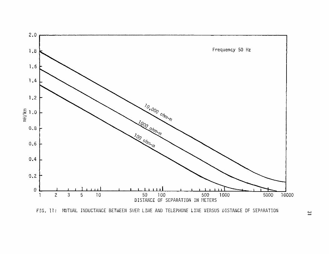
11. MUTUAL INDUCTANCE BETWEEN SWER LINE AND TELEPHONE
LINE VERSUS DISTANCE OF SEPARATION •••.•...••....•.•.•..•...•..• 31
12. ELECTROSTATIC AND ELECTROMAGf~ETIC INDUCTION VERSUS
SEPARATION BETWEEN SWER LINE AND TELEPHONE LINE .••••••.•.•••.•• 32
13. HARMONIC CURRENT DISTRIBUTION UNDER SWER POWER LINE •••.•.•.•••• 34

vii
List of Figures (continued) Page
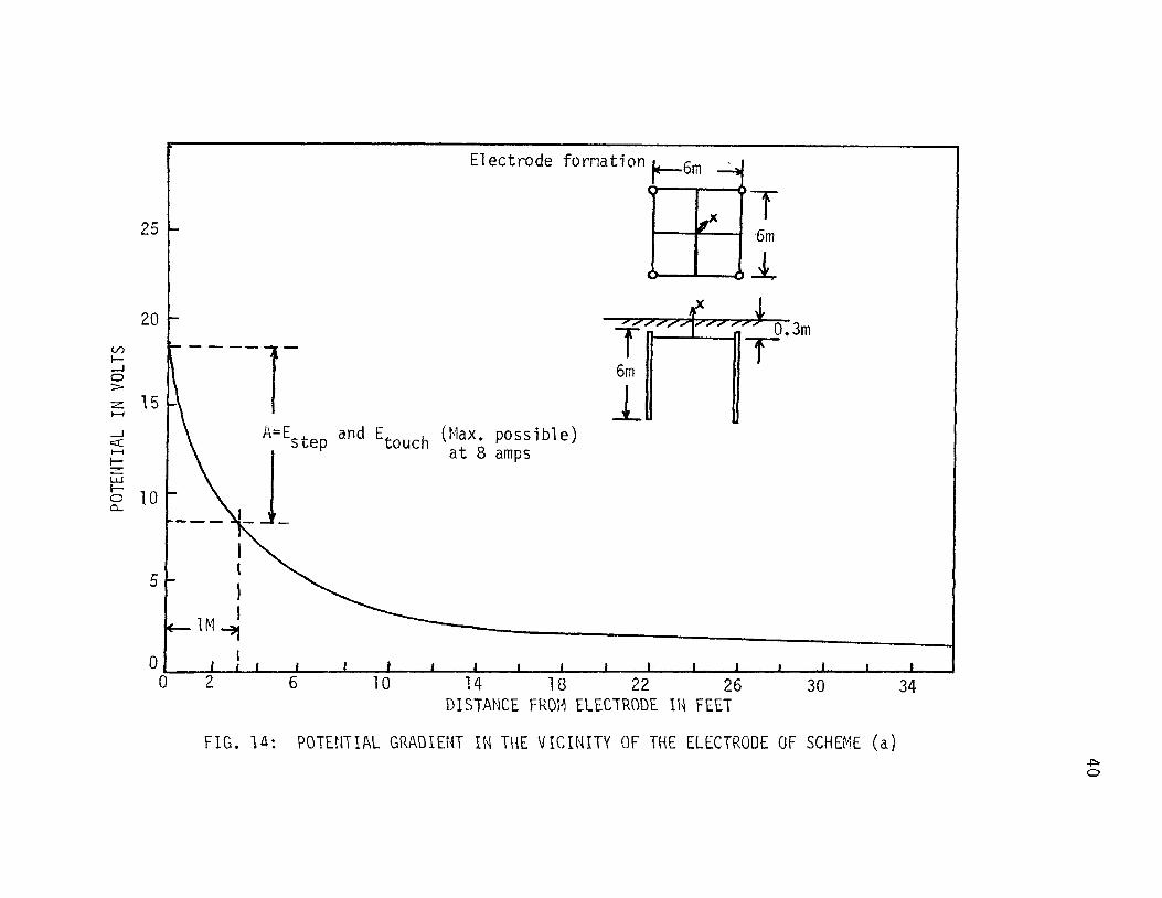
14. POTENTIAL GRADIENT IN THE VICINITY OF THE
ELECTRODE OF SCHEME(a) .•••••.••••••••••.••.••••••••••••••.•••• 40
15. POTENTIAL GRADIENT IN THE VICINITY OF THE
ELECTRODE OF SCHEME(b) ••.•••.••••••.••••••••.••.•.•••••••••••• 41
16. CAPACITOR TYPE PHASE CONVERTER •••••••••.••••.•••...••.•••••.•• 49
17. CAPACITOR-REACTOR TYPE PHASE CONVERTER •••••••••.•••••••••••••• 53
18. AUTO-TRANSFORMER CAPACITOR TYPE PHASE CONVERTER .•••••.•••.•••• 58
19. SPHERICAL ELECTRODE •..••••••.••••••••••••••••••••••••••••••••• 64
20. ELECTROSTATICALLY INDUCED E.~1. F. IN TELEPHONE
LINE •••.•••••.•..•••••••••.•••..•..•.•.••..•••••..•••••••••••• 66

viii
LIST OF TABLES
Table Page
I. SOIL RESISTIVITY •••••••••••••••..•..•.••••••••••••..••.•.••••. 15
II. GROUND PATH RESISTANCE AND DIAMETER OF COPPER
CONDUCTOR HAVING THE SAME RESISTANCE PER ~1 •••••••••.••••••••• 19
III. RESISTANCE OF VARIOUS EARTH ELECTRODES •••••.••••••.•••.•.•••.. 26

1
I. INTRODUCTION
More than 85% of the population of India is in villages. The
progress of the nation depends mainly on the progress of the rural
population. A majority of the village population is engaged in agri
culture and small percentage in small scale industries of a varied
nature. To improve the rural economy, it is necessary to adopt modern
methods of agriculture and mechanisation of small scale industries.
The Govt of India is running a 11 Grow more food 11 campaign, thus giving
the improvement of rural economy a high national priority. One of the
ways this can be attained is by supplying electric power to the rural
areas.
Rural India comprises a very large number of sparsely populated
villages located at varying distances all over the country. The
villages v-1hich have populations above 2000 are already electrified
with three phase or single phase supply. Their number is only 10% of
the total number of villages in India. The rest of the villages are
10 to 15 krns a~Jay from the present supply 1 i nes and have populations
less than 2000. Most of the villages have a population of 500 or even
less. The electrical load is mostly water pumps for irrigation and
domestic lighting. In some villages there may be some processing
industries based on agriculture products. The demand for electric
power is mostly seasonal and that too with very low load factor except
for domestic lighting. Hence the supplier of electric pm1er has great
difficulty in equating revenue and expenditure. To close the gap
every attempt is made to develop load demand and to effect a reduc
tion in capital, operation and maintenance expenditures, on rural

sub-stations and distribution lines. To supply an individual farm,
whose average load is 5KVA, the expenditure by the electric supply
authority is usually at least ten tir11es the capital cost incurred in
supplying a typical suburban home. In rural areas, therefore, it is
essential, consistent \-.rith technical considerations, that every kno~m
economy of construction be employed.
There are three methods of rural electrification which can be
considered:
a) Three phase system
b) Single phase system
c) Single phase single Hire system (Sl·JER)
2
The object of this project is to investigate the practicability of
using a single line \Jith ground return for small rural lines v1here the
loads are isolated and their supply by a regular line is uneconomical.
Most of the problems associated with SWER are discussed in the next
sections together with possible solutions. Such systems have success
fully been used in New Zealand and Australia where the load density is
low for supply to isolated farms.
The systeT'il layout studied is shm:n in t='ig. l. It consists of one
single phase isolating transformer 11ith a transformation ratio of one
to one. As the standard voltages of distribution are 11, 22, and 331<V
for rural areas. The ground return syster.1 should 110rk at 6.33KV,
12.7KV and 19.05KV for proper co-ordination vdth the existing system.
The primary winding of the isolating transformer is connected to tile
existing lines. One terminal of the secondary \IJinding of tile isolat
ing transformer is solidly earthed and the other terminal is connected

11 KV ISOLATING TRANSFOR~1ER 6. 33KV
------ ---~
FIG. 1: SCHH1ATIC DIAGRAf·1 FOR SWER
UISTRIBUTION TRANSFORMER
""="'
400V
j_
w

to a single wire 1 i ne. The same type of arrangement is er,lp 1 oyed at
the distribution sub-station. The midpoint of the secondary winding
of the distribution transformer is also earthed.
4
The earth is used as a return conductor in this case. The second
method is not to use an isolating transformer, but to connect the 11 KV
line directly to the distribution transformer. The disadvantage of
this system is that ground current has to travel a 1 ong \Jay back to
the main transformer which may be quite far. This is undesirable, due
to interference in telecommunication systems as discussed in a later
section. The most serious problem of SWER system is danger to humans
and animals due to potential gradients near the vicinity of the earth
electrode because the current flows through the ground continuously.
The following points are discussed in detail in this investigation:
a) Economic consideration of transmission and distribution by SWER
system and phase converter costs.
b) Technical considerations of S~~ER system such as earth conductivity,
different types of electrodes, heating of electrode, co-ordination
with communication lines and danger to humans and animals.
II. ECONOMIC CONSIDERATION OF SWER SYSTEM
A. TRANSMISSION AND DISTRIBUTION COSTS
On account of considerable reduction in capital cost effected by
the use of single wire earth return systems, distribution of electric
power to rural areas is a very attractive proposition.
The economics of ground return system may vary from country to
country depending upon the nature and extent of load, labor and mate
rial costs. It should also be noted that the voltage of distribution
adopted determines the capital cost. However, distribution voltages
between 4.6KV and 13.2KV will not vary the capital cost very much,
because the cost of line materials in this voltage range does not
differ appreciably. But the amount of power that can be distributed
rises considerably as higher voltage of distribution is adopted. In
case of 33KV distribution, the cost of line materials and other asso
ciated equipment is twice that of 11 KV 1 ine per km, but the amount of
power that can be transmitted outweighs the cost differential.
5
The single wire earth return system (SWER) derives its economy
from the fact that it employs earth as one conductor. This reduces
the initial investment, not just equivalent to the cost of the conduc
tor and its accessories only, but reduction occurs from lesser number
of supports required, no cross-arms and reduced labor and transporta
tion charges. The economics of the system depends on the length of
the line and whether the isolating transformer has been installed in
the system or not. It improves with the length of the line, but the
isolating transformer, the use of which is not ah1ays necessary, has

6
an adverse effect on the cost \vhi ch is more pronounced \Jilen tile length
of the line is not more than four or five kms.
The cost of the SWER system 11ith 6.33KV lines, both v1ith and
~·Jithout the isolating sub-station has been \forked out 11/ith line
lengths varing from one km to thirty km in steps of one km. Corres
ponding estimates have been prepared for the conventional single phase
two wire and three phase systems also, on the basis of prevailing
market rates of materials and 1 abor. The 1 oads assumed are 251(VA and
50KVA, i.e., ten isolated customers each having a load of 5KVA in the
case of 50KVA load and five customers each having a load of 5KVA in the
case of 25KVA load. It is assumed that each customer is supplied from
a separate, pole mounted distribution transformer. ACSR conductor
equivalent to 4AWG copper on wood supports is considered suitable for
the 1 ine. The same conductor has been used in the estir11ates for the
single phase two wire system. For three phase syste111 the conductor
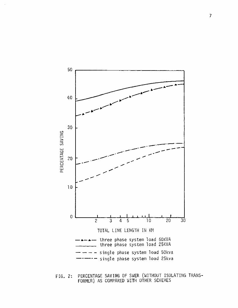
size is 6AWG. The results are given in Fig. 2 and Fig. 3.
The percentage saving by using SIJER as compared vlith three phase
and single phase two wire system of distribution at 25KVA and 50KVA
loads versus total line length are plotted. From Fig. 2, it can be
seen that the percentage saving by using SWER, without an isolating
transformer, varies with total length of distribution line and the
total load delivered. Fig. 3 shov1s the percentage saving, \vith iso
lating transformer included. It can be seen that it is not economical
to use SWER if the length of the total distribution line is less than
five kms when compared with single phase two wire systems of distribu
tion.
c..!:! z ....... > c::( (./')
ll..l (.!) c::( 1-z ll..l u 0::: w CL
50 r-------------------------------~
40
30
20
10
-·---
.-· -· ........... . .-·
--·---· -· -...,..
......... -----· .--• -· -------
TOTAL LINE LENGTH IN Kt·1
-~-~- three phase system load 50KVA three phase system load 25KVA
----single phase system load 50kva -------·- single phase system load 25kva
FIG. 2: PERCENTAGE SAVING OF SWER (WITHOUT ISOLATING TRANSFORMER) AS COMPARED WITH OTHER SCHEMES
7

50
40
~ 30 ........ > <::::( V)
w (!':) <::::( I-
~ 20 u 0::: LJ..J 0...
10
0
1 2
-·-·-
3 4 5 10 20 30
TOTAL LINE LENGTH IN Kf,1
three phase system load 50kva
three phase system load 25kva single phase system load 50kva
single phase system load 25kva
FIG. 3: PERCENTAGE SAVING OF S~JER (WITH ISOLATif~G TRANSFOR~1ER) AS COMPARED WITH OTHER SCHEMES
8
9
The SWER system has been developed especially for use in sparsely
settled areas and its application is restricted to such areas Hhere
Kw loading is about 2Kv.,r/km and Hill not increase with time to cause
line currents in excess of eight amps. It is not recommended that use
be made of SWER system where the K\IJ loading \'Jill steadily increase and
double itself in eight or ten years. A normal SHER line is not easily
convertible to a three phase line. Attempts to provide for later con
version will reduce considerably the economics of the SWER system, and
subsequent conversion could be difficult and costly.
The eight amps limit in the ground current is adopted due to
safety reasons and to reduce the interference in telecommunication
lines as discussed in a later section. With this limit a SWER system
with a voltage of 6.33KV can deliver 50KVA load and at 12.7KV a load
of lOOKVA. Most of the villages in India are Hithin 12kms from the
present llkv, 22kv and 33kv distribution system. It is assumed that
the tota 1 1 ength of the SWER system will not exceed thirty Kms.
B. PHASE CONVERTERS COSTS
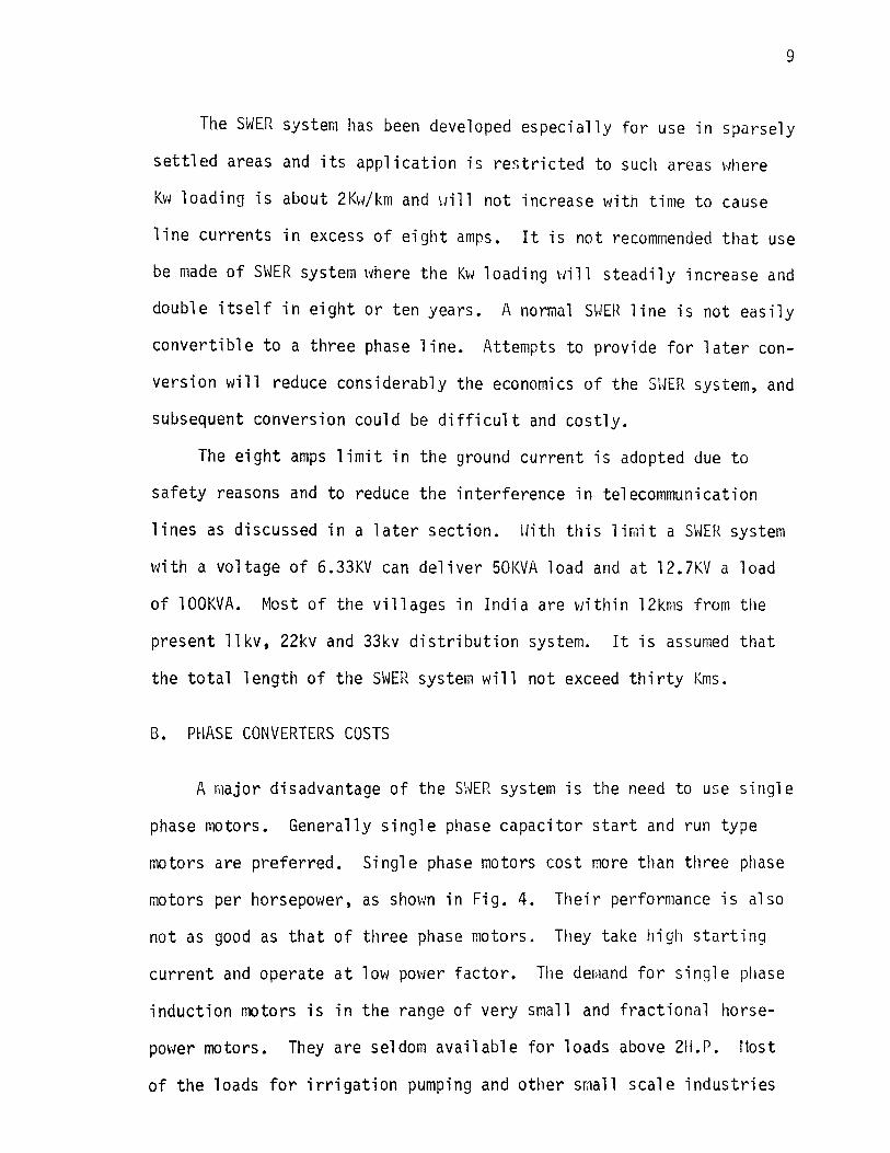
A major disadvantage of the SHER system is the need to use single
phase motors. Generally single phase capacitor start and run type
motors are preferred. Single phase motors cost more than three phase
motors per horsepower, as shm-m in Fig. 4. Their performance is also
not as good as that of three phase motors. They take high starting
current and operate at low pm1er factor. The demand for single phase
induction motors is in the range of very small and fractional horse
power motors. They are seldom available for loads above 211.P. f1ost
of the loads for irrigation pumping and other small scale industries
V') 0::: o:::c: _J _J 0 0
z: .......
1-V')
0 u
10000 r----------------
5000
2000
1000
700
500
300
200
100
50
1 1
.-/ .,/'
~
2 3
~
Drip proof, fan cooled for a temperature rise of 40°C. Speed: 1500RPM
5 7 10 15 20 30 50
MOTOR H.P.
three phase
100
-•-•- sinale phase
FIG. 4: COST OF SirlGLE PHASE Arm THREE PHASE INDUCTIOrJ NO TOR VERSUS t·!OTOR ll. P.
10

based on agricultural products are between the range of 3 H.P. to
7.5 H.P. Repulsion-induction motors can supply such loads, but at
much higher costs.
11
To operate a three phase motor on a single phase supply, phase
converters are used. They are of tHo types, static and rotary. Static
phase converters are used with individual three phase motors and
rotary phase converters to operate a group of three phase motors. \~e
will consider only static phase converters here.
A static phase converter is a device which supplies polyphase
power to a load from a single phase source using only passive circuit
elements. Ideally such equipment should produce balanced polyphase
voltages at all loads. The losses in these elements should be kept
to a minimum to obtain a high efficiency of conversion. The criterion
for selecting the phase converter parameters is to give balanced
voltages at the terminal of the load. One measure of the unbalance is
the ratio of the negative sequence component of the current to the
positive sequence component. The three schemes most commonly used are:
i) Capacitor only.
ii) Capacitor-reactor.
iii) Auto-transformer- Capacitor.
Analyses of the circuits and calculation of the circuit elements
for each of the above schemes are given in Appendix A, l3 and C, res
pectively. It can be seen that, for a specified slip, the proper
sel~ction of the circuit elements will give balanced operation at full
load except in the case of the capacitor only scheme. In the latter
scheme perfect balance can not be obtained at full load. Experimental
results by Huber (1) confirms this. He has concluded that the auto-

12
transformer capacitor scheme will give balanced operation at full
load without exceeding the name plate value of line current of a 30
motor. But in the case of the capacitor only scheme, due to overheat
ing caused by excessive current in one phase at full load, the r:10tor
has to be derated by 25% to keep the currents in all the three phases
within the name plate value. Sharma( 2) has concluded that the
capacitor-reactor scheme gives balanced operation at full load and
the current in all three phases does not exceed the name plate value.
It is also concluded that starting torque varies from 175% to 200% of
full load torque of the motor when the motor is used in conjunction
with phase converters. The overall efficiency of the motor is reduced
by 2% due to phase converters.
The cost of different types of static phase converters and the
magnetic starter versus load are shown in Fig. 5. The cost of static
phase converters plus the three phase motor (drip proof, fan cooled
for 40°C temperature rise) versus motor H.P. are shown in Fig. 6. It
can be seen that the capacitor only scheme together Hith three phase
motor is still cheaper than the single phase motor of the same horse
power even when the three phase motor must be derated by 25%.

(/) 0::: <:::( _J _J
0 0
:z: ........
1-(/) 0 u
lOOOOr--------------------------------
5000
2000
1000
500
300
200
100
50
,---1 I I r--'
I ,-----J I
.,; I - ____ _s-----'
1~--~~~-L~~--L-~~--~--~--~ 1 2 3 4 5 7 1 0 1 5 20 30 50 1 00
-·-·-· -·-·-
LOAD H.P.
auto-transformer capacitor
capacitor only
capacitor-reactor
magnetic starter
FIG. 5: COST OF PHASE CONVERTER AND MAGNETIC STARTER VERSUS LOAD H.P.
13

(./) 0::: c::r::: _J _J 0 0
z -1-(./) 0 u
10000 .-----------------
5000
3000
2000
1000
500
300
200
100
50
Without magnetic starter. Speed: 1 500RP~1
1 ~--~--L---~-L~--~~--L-~~---J 1 2 3 5 7 1 0 1 5 20 30 50 l 00
MOTOR H.P. 3 ~ motor + capacitor-auto transformer
- • -·- 3 ~ motor + capacitor only
-•-a- 3 ~ motor + capacitor-reactor
FIG. 6: COST OF PHASE CONVERTER PLUS THE COST OF THREE PHASE INDUCTION MOTOR VERSUS MOTOR H.P.
14

15
III. TECHNICAL CONSIDERATION OF SWER SYSTEM
A. EARTH AS A CONDUCTOR
1. SOIL RESISTIVITY
Soil resistivity depends upon the type of soil and, therefore,
varies with distance as well as depth. If no specific measurements
for a definite spot of ground are made, the figures of Table I may be
used as an average resistivity through the ground. (3)
Table I: SOIL RESISTIVITY
Type of Organic Moist Dry Bedrock Unit ground wet soil soil soi 1
Res is-1 o2 103 1 o4 tivity 10 ohm-meter
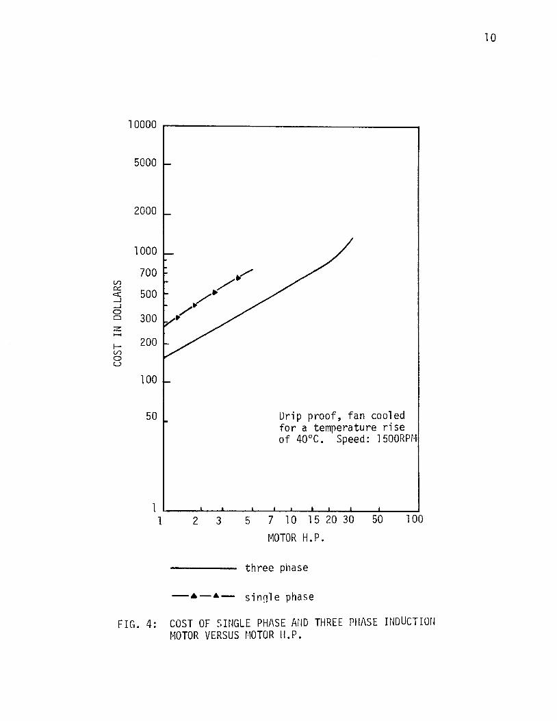
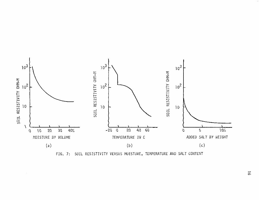
Further the resistivity is much lower below the subsoil water
level than above it. In frozen soil, as in a surface layer in winter,
it is particularly high. The resistivity of a certain soil also
varies with moisture, temperature and salt content of the soil (3) as
shown in Fig. 7. The above factors serve to indicate that, though
earth may be considered as a conductor of practically unlimiting con
ducting capacity, yet its resistance is largely determined by its
chemical ingredients and the amount of moisture present in it. That
is why it varies from place to place and from time to time. It is
therefore necessary to measure the resistivity of earth in the area
where a SWER system is planned.
103 ~\ 103 103
-- ::::: "'--I I - ::E "'-
::E 6 :I:
I 0 ::::
l o2 s 102 >- >-1 o2 1- 1-
........ ........ >- > > 1- ........ ........ ........ 1- 1-> U') U')
...... ........ ........ 1- U') U')
~ 10 l..i.J LJ.J a:: 10
0::: 10 U')
LJ.J .....1 .....1
a: ......... ....... 0 0
.....l U') U')
....... 0 U')
"\ \ \ \ \ \
Q \ (\ ~(\ 3(\ 4<l% -Z<l G Z<l 40 60 (\ 5 \(\%
l·?DISTURE BY VOLUME TEMPERATURE IN C ADDED SALT BY WEIGHT
(a) (b) (c)
FIG. 7: SOIL RESISTIVITY VERSUS MOISTURE, TEMPERATURE AND SALT CONTENT
....... 0'\
17
2. DISTRIBUTION OF EARTH RETURN CURRENT IN THE GROUND
According to Rudenberg(3), the flow of earth return current
between two earth electrodes occurs in the form of streamlines radi
ating in space from the electrode. This behavior is particularly true
in case of DC, but for AC, the distribution is modified due to the
inductive effect of the magnetic field of ground current, except very
near the electrodes where the local resistance dominates. Elsev1here
the distribution is so modified that the energy of the magnetic field
of the ground current and hence its self inductance tend to be mini
mum. Hence the AC return current through the ground does not spread
to as great a distance as does direct current but concentrates on
paths in closer proximity to the overhead line conductor itself.
It has been proven by Rudenburg that the return currents in the
ground spread with power transmission frequencies, as far as some kilo
meters, with audio transmission frequencies as far as some one hundred
meters over the surface and into the depth of the earth.
3. RESISTANCE AND INDUCTANCE OF THE GROUND RETURN PATH
According to Rudenberg(3), the effective resistance of the ground
return current path is given by
R = (~2 ·ft) x 10-7 ohms
where
f = supply frequency Hz
1 = length of ground path in meters
It should be noted that the resistance of the earth path is dependent
upon the frequency of current and length of path but is independent of

earth resistivity.
where
The inductance of the ground return path is
L = 2Ln 56~· 8 (~) 1 1 2 •10-4 H/km
h = height of conductor above ground in meters
p = resistivity of earth in ohm-meter
At power frequency (50Hz) when h is ten meters and earth resis
tivity if one hundred ohm-m, the value of inductance is 0.88mH/km or
0.28ohm/km. This is about half the value of the self inductance of
the conductor as caused by the field lines in air above the ground
and supplements this inductance. The inductance given by the above
equation is proportional to length of line and depends on the height
of the transmission line and to a lesser degree on resistivity of
earth and frequency of the current.
18
Table II gives the return path•s resistance in ohm/km for various
frequencies in moist soil of resistivity 100 ohm-m. The same return
resistance would be obtained by a fictitious copper Hire of an equi
valent diameter d as given in third line of the Table II. The self
inductance of a fictitious conductor of diameter d and depth D under
the surface, the ohmic and inductive effect of v1hich may be taken
equivalent to those of ground return path can be calculated. By
comparison of the above equation with the self inductance of such an
ideal return system, the equivalent depth can be calculated. The
values for equivalent depths is shown in the last row of Table II.
The resistivity of earth is assumed constant throughout, i.e., p =
100 ohm-m.
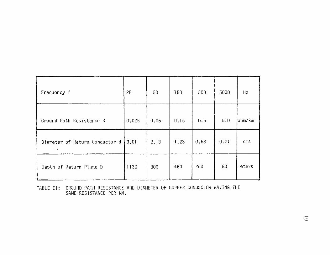
Frequency f 25 50 150 500 5000 Hz
Ground Path Resistance R 0.025 0.05 0.15 0.5 5.0 ohm/km
Diameter of Return Conductor d 3. Ol 2. 13 1.23 0.68 0. 21 ems ''
Depth of Return Plane D 1130 800 460 250 80 meters
TABLE II: GROUND PATH RESISTANCE AND DIAMETER OF COPPER CONUUCTOR HAVING THE SAME RESISTANCE PER KM.
i I
i I
I
__. 4.0

20
B. GROUNDING ELECTRODES AND GRIDS
For the transfer of po\tler through earth, it is necessary to have
ground electrodes at each end of the 1 ine, through \·Jhich the current
is conveyed to the earth. The resistance of the grounding arrangement
constitutes the major part of the total resistance of the ground
return path.
As a matter of fact, when vie measure the earth resistance of an
electrode by the usual method with an earth tester we actually
measure:
i) The resistance of the electrode along with its connection.
ii) The resistance between the electrode and the ground in the
immediate vicinity of the electrode. This is usually kno\'m
as local resistance.
iii) The resistance of the soil in between the spike and the
electrode.
Obviously item (i) is small and so also is (iii). It is rather
the local resistance which accounts for most of the measured resis-
tance. The main factor governing the local resistance are the resis
tivity of the surrounding earth and the nature of the electrode
employed.
There are many types of earth electrodes used. Some of them are
considered here. Schwarz(4) in 1954 developed analytical expressions
for various grounding systems and compared the results with the exper
imental results with very close agreement.

21
1. DEEP DRIVEN ROD OR PIPE
The resistance of driven rods can be found by the equation given
bel0\'1:
v1here
R = _P_ Ln d2.Q, ohms 2n.Q,
.e. 2£ = 0.366 .Q, log10 ~ ohms.
P = resistivity of earth in ohm-m •
.Q, =length of the electrode !JelmJ ground in meters,
d = diameter of rod or external diameter of pipe in meters.
It can be seen from the above equation that the resistance
decreases rapidly as the length of the electrode increases and also
less rapidly as the diameter increases.
2. MULTIPLE ELECTRODES IN RECTANGULAR AND SQUARE PATTERiJ
It is sometimes necessary to drive a number of rods or pipes and
connect them in multiple to obtain the desired low resistance of the
grounding system. To obtain best results attention must be paid to
the spacing of these multiple rods. It is found that 90% of the
resistance to earth is situated within an area the radius of which is
roughly equal to the length of one rod. The electrodes should thus be
spaced far enough a\'Jay from each other so as not to overlap the resi s
tance area of their neighbors. The resistance of an array of rods
can be calculated by the following equation:

22
where
n = number of rods or pipes in an area A square meters.
2b = diameter of rod or external diameter of pipe in meter.
21 = length of each electrode bel 0\1 ground in meters.
kl = constant to be determined from Fig. 9 (a).
p = resistivity of earth in ohrn-m.
Fig. 8 shows how the resistance varies \lith the number of
electrodes used and spacing between them.
3. GRIUS
Grid is a grounding system consisting of a conductor, forming a
square or rectangular pattern, buried beneath the surface of earth.
Resistance of a grid is given by
v1here
ohrns
~ = length of grid conductor in meters.
d = diameter of grid conductor in meters.
H = depth of burial of grid conductor in meters below earth
surface.
A = area of grid in square meters.
k1&k2 = constants to be determined from Fig. 9(a and b).
p = resistivity of earth in ohm-m.
4. COH()WATION OF ROD fJEIJS ANO GRIO
The resistance of the combination can be found by the equation

WJ Cl 0 0::. I-u WJ .....J WJ
WJ z c Ll.. 0
WJ u z c:( I-(/) 1-t v, w 0::.
1--z WJ u 0::. w CL
0
10
20
30
40
50
60
70
80
90
100
1
-·-·-·-·-· . ...--• .. -- ----- ------/ . ....-::...--
,r • // /:/ ~;/
' ., / )// fJ•!
r''/ ~ ~
~
2 3
---spacing is 12m -•-•- spacing is 6m ----spacing is 3m
4 5 6 7
t~W·1BER OF ELECTRODES 8
FIG. 8: RESISTANCE OF MULTIPLE ELECTRODES OF VARIOUS SPACING AND OF DEPTH 3m (IN TERMS OF % RESISTANCE OF ELECTRODE) AS A FUNCTION OF THE NUMBER OF ELECTRODES N
w

1.45
1.35 ....... ~
1- 1.25 ;::::: L.LJ - 1.15 <....) -LL. LL.
1.05 L.LJ 0 <....)
0.95
0.85 2 4 6 8
LENGTH TO WIDTH RATIO OF AREA A
(a)
7.5
~6.5 1-
~ 1-z 5.5 LJ..I -- k2 <....)
........ LL. 4. 5 1-LL. L.LJ 0
I I I I I I <....) 3.5 I
0 2 4 6 8
LENGTH TO ~JIDTH RATIO OF AREA A
(b)
FIG. 9: CURVES FOR COEFFICIENTS K1 AND K2
24

R R - R 2 R = . rb 9 'm
Rrb + Rg - 2Rm ohms.
where Rm is given by the equation
R = .f?._ [Ln 2.Q. + k .Q. k, + 1] ohms. m 1T£ .Q.l 1 lA -
.Q. = length of grid conductor in meters
t 1 = length of electrodes below ground in meters.
A = area covered by the combination in square meters.
k1&k2 = constants from Fig. 9(a and b).
Table III shows resistance of various electrodes for different
25
values of earth resistivity. There are certain configurations of
electrodes and grids which can not be handled by the above equations.
For these configurations, model tests are made. A scale model of the
electrode or grid or the combination of both is placed in a tank of
electrolyte whose resistivity is known and resistance is measured by
passing a current through the electrode. The potential gradient at
the surface of the electrolyte is also measured.
C. HEATING OF GROUUD ELECTRODES
Flow of current continuously through the ground electrode for
supplying pmJer to any load will heat up the electrode and the ground
surrounding it. For calculating the temperature rise in the soil for
a certain loading an equation is developed in Appendix U Hhich is
given as fo 11 ows:
in degrees centigrade
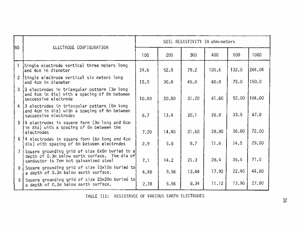
NO ELECTRODE CONFIGURATION
l !Single electrode vertical three meters long and 4cm in diameter
2 !Single electrode vertical six meters long and 4cm in diameter
3 13 electrodes in triangular pattern (3m long and 4cm in dia) with a spacing of 6m between successive electrode
4 13 electrodes in triangular pattern (6m long and 4cm in dia) with a spacing of 6rn between
100
24.6
15.0
10.40
successive electrodes I 6.7 5 14 electrodes in square form (3m long and 6cm
in dia) with a spacing of 6m between the electrodes I 7.20
6 14 electrodes in square form (6m long and 4cm dia) \'Jith spacing of 6m between electrodes I 2.9
7 I Square grounding grid of size 6x6m buried to a depth of 0.3m below earth surface. The dia of conductor is 7mm hot galvanized steel I 7.1
8 I Square grounding grid of size lOxlOm buried to a depth of 0.3m below earth surface. I 4.48
9 I Square grounding grid of size 20x20m buried to a depth of 0.3m below earth surface. I 2.78
SOIL RESISTIVITY IN ohm-meters
200 300 400 500 1000
52.8 79.2 105.6 13 2 • 0 12 64 • 04
30.0 45.0 60.0 75.0 1150.0
20.80 31.20 41.60 52. 00 11 04. 00
13.4 20.1 26.8 33.5 I 67.0
14.40 21.60 28.80 36.00 I 72.00
5.8 8.7 11.6 14.5 I 29.00
14.2 21.3 28.4 35.5 I 71.0
8.96 13.44 17.92 22.40 I 44.80
5.56 8.34 11.12 13.90 I 27.80
TABLE III: RESISTANCE OF VARIOUS EARTH ELECTRODES N 01
where
I = current flowing through electrode in Amps
R = resistance of ground connection in ohms.
27
A = heat conductivity of soil in ~·Jatts/°C-m (taken as 1.2 ~J/°C-m)
e = temperature rise in oc
p = resistivity of earth in ohm-m
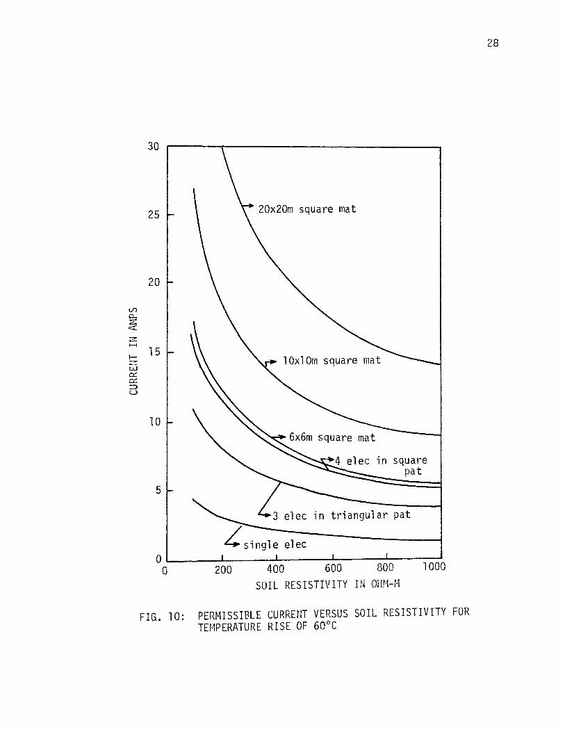
If the temperature rise is such that its value at the electrode
surface is 100°C, the moisture in the soil \'Jill be evaporated and a
thin dry layer of soil vlill be formed around the electrode or possibly
some vapor \'Jill be generated \·1hich will form a film betvJeen the elec
trode and the soil resulting in a large resistance increase and com
plete interruption of the circuit. For safety 60°C may be taken as
the maximum permissible temperature rise.
The permissible current vdll be l0\'1 for high resistivity and high
for loH resistivity. The permissible current for various resistivities
are given in Fig. 10 both for isolated electrodes and for grids.
In the case of grids the temperature rise of the soil Hill be lo~'/
because total current flowing into the ground is distributed through
out the grid conductors. So the maximum current that can flow through
grids may be higher than that of isolated electrodes of the same
resistance.
D. CO-ORDINATION ~HTH TELECQr.1~iUfHCATION CIRCUITS
Communication circuits running near the S~~ER \'Jill have induced
voltages due to electrostatic and electromagnetic coupling. The
electrostatically induced voltage in communication circuits due to
SWER will be considerable as compared vJith single phase two Hire line
V) 0.. :::E: o=:t:
z ....... I-z w 0:::: 0:::: :::::::l u
30
25
20
15
10
5
20x20m square mat
lOxlOm square mat
L single elec
in square pat
in triangular pat
0~----~------~------L-----~----~ 1000 0 200 400 600 800 SOIL RESISTIVITY IN OIIM-r~
FIG. 10: PERMISSIBLE CURRENT VERSUS SOIL RESISTIVITY FOR TEMPERATURE RISE OF 60°C
28

29
or three phase systems, because the positive and negative charges are
separated by the distance equal to tv,rice the height of line supports.
The derivation of the equation given belo\J is shmm in Appendix E.
vJhere
e s - __;2:;:...,.,-_ hk
E - L n 4 ~ X -( a"""'";2~+__:.h ~2 +-k-:::-2-)
h = height of SWER line above ground in meters and a conductor
dia d meters.
k =height of communication line above ground in meters.
a = distance of horizontal separation in meters.
es = electrostatically induced e.m.f. in volts
E =working voltage of SWER line in volts.
The predominating cause for interference is mutual inductive
coupling betv1een the SvJER system and the communication line. The
magnetic flux produced from a current flowing in a loop is proportional
to I•A/£ \vhere I is the current in the loop, A is area of loop and t
is the length of magnetic path. This magnetic flux links vlith commu
nication lines and induces voltages in them. The loops encountered in
high resistivity soil are larger than in lov1 resistivity soil. The
extent of the induced e.m.f. depends on the magnitude of the earth
current, soil resistivity, the separation of SWER from the circuit and
the length of parallelism of both lines. Required separation distances
can be calculated. A formula \'Jas developed by Radley( 5) in 1931
volts
where
M = mutual inductance in H/km

I = current flO\dng in the ground circuit in J\mps
t = length of parallelism in kms.
w = 2nf Hhere f is the frequency of supply in Hz.
em= electromagnetically induced e.m.f. in volts.
30
I~ can be obtained from Fig. 11 for a particular earth resistivity
and separation. The directives of the International Consultive
Committee on telephones (C.C.I.F.) Hhich prescribes that the total
voltage induced, i.e., both electromagnetic and electrostatic, in
telephone lines because of the presence of a power line shall not
exceed 60 Volts under normal conditions and 430 Volts under fault con
ditions. These limits call for a certain distance of separation
between SWER and communication line.
In Fig. 12, variation in electrostatic and electromagnetic
induced voltages with separation are shO\-m. The graphs are dravm for
a SWER line operating at 6.33KV and at 8Amps full load. In the case
of electromagnetic induction for earth resistivities of 10,000, 1000
and 100 ohm-m the induced voltages are plotted. If the length of
parallelism of the lines is known the safe separation distance between
the lines can be calculated from Fig. 12. For example if the length
of parallelism is 20kms, the earth resistivity is lOOohm-m then a safe
separation distance about lOOm will keep the induced voltages below
60 Volts.
A closer approach than lOOm is permitted \Jhen absolutely
necessary such as deviation to\'lards the telephone line for special
reasons as to enable it to reach a consumer's premises which might be
situated close to a telephone line or to avoid major obstructions such
2.0------------------------------------------------------------------~
1.8 Frequency 50 Hz
1. 6
1 .4
1.2
~ 1.0 ....... :I: E
0.8
0.6
0.4
0.2 0 I I I I I I I I I I I I I I I I I I I I I I I I I I I I p I I :r==-. I
1 2 3 5 10 50 100 500 1000 5000 10000 DISTANCE OF SEPARATION IN f·1ETERS
FIG. 11: MUTUAL INDUCTANCE BETWEEN St~ER LINE AND TELEPHONE LINE VERSUS DISTANCE OF SEPARATION w ......

lO.Or-----------------------------~1000
res 10,000 ohm-m 5.0
Soil res 1000 ohn-m
~ 3. 0 ~~---L.1
ffi 2.0 0..
:.n 1-5 1.0 >
Q)eo. s z 0
~ 0.3 (._)
::> @ 0.2 ....... u ....... 1-w 0.1 z c.!' c::( :E: 0 0::: 1- .05 (._) w _J w
'\ .. \'.\
'. .. \Soil res \\ 100 ohm-m
\ . \. \
\ . \\
\ . \\
----em \ •
-•-•-es at 12.7 KV\ \ - ·- · -e5 at 6.33 KV \\ •\
.01 ~--_.--~._~~ .. ____ ._\_.•~_. .. ~ 10 50 100 500 1000
SEPARATION IN METERS
500
200
100
50
30
10
5
1
U1 1-_J
0 >
.......
c...> ....... s U1 0 0::: I(._) w _J w
FIG. 12: ELECTROSTATIC AND ELECTROt-1AGNETIC INDUCTION VERSUS SEPARATION BETWEEN SHER LINE AND TELEPHONE LINE
32
33
as clumps of trees or groups of uuildings. HoVJever, provision should
be made that the effect of such an approach must be offset by greater
separation over other portions of the same continuous length of
parallel in order that the induction into the telephone line shall be
no greater than if the separation over the whole length of parallelism
had been uniform.
Interference(noise) in communication lines is also produced by
corona effects and harmonics in pov~er lines. Corona noise can be
reduced by careful design of the line hard\\'are. According to Robert
son(6), the reactance of the earth return path is a function of fre-
quency. The harmonic currents which are usually associ a ted with 1 0\'1
power factor magnetizing currents are confined to a path in earth
nearly beneath the overhead conductor than the fundamental frequency
currents, as shown in Fig. 13. It has been determined by the above
author that charging currents of SvJER 1 i ne at 11 KV is only 0. 03 amp/
mile. These charging currents can be offset by magnetizing currents
of the transformer (a 5 to lOKVA transformer has a magnetizing current
of about O.Ol5amps). So charging currents presents no major problem
of co-ordination with communication lines.
E. SAFETY
One of the natural effects of current flov1 through an earth
electrode is that a voltage gradient is present on the surface of the
earth in the immediate neighborhood of the electrode. The fundamental
reason for this potential gradient is that the current of the electrode
is not concentrated at one point, but is distributed over the soil in
its vicinity.

:I: IC.. I.J..J r:::l
r:::l z c:(
il ""~,___ __ 0
DISTANCE
FIG. 13: HARMONIC CURRENT DISTRIBUTION UNDER SWER POWER LINE
34
35
1. STEP VOLTAGE
The term step voltage means the potential difference Hhich exists
between foot to foot contact when a person takes a stride near a sub
station when current flows through earth electrode.
If a current of I amps floHs through an electrode (the electrode
is assumed to be hemispherical) then the current density at a distance
x meters is given by
J I = 2TIX2
I
2'1TX2
then electric field strength at the surface of the earth will be
E = pJ r volts/m (p = resistivity of eurth ohm-m)
_ PI - 2'1TX2
volts/m
if a man or animal is \'Jalking near the electrode, a voltage vJhidJ may
cause serious damage may be impressed. Let \1 meters be the width of
the step.
The step potential can be calculated as follovJs
E = s
therefore
x x+w x+VJ -J E •dx = )( E •dx = el J dx volts. r r 2'1T 2
X x+w x x
E =.el H s 2'1T x(x+w) volts
From the above equation it can be seen that the step voltage depends
on the ground current, the distance from the electrode, the resis
tivity of the ground and on the step vddth.
Actually the danger to living creatures is due to the current
passing through their bodies rather than on the magnitude of the


37
In the sub-station area Ps' the resistivity of earth just beneath
the feet can be increased by using crushed rock bed surfacing, which
has a resistivity of 3000 ohm-m even under \vet condition, of depth
4 inches to 6 inches. In case of animals, step voltage is the poten-
tial difference shunted between fore and hind legs. The step voltage
for animals is of high value since the distance shunted between fore
and hind legs could be twice as great as man. It is difficult to
calculate the step voltage for different animals due to absence of
knowledge regarding their body resistance. According to Robertso~6 ) experiments were carried out to ascertain the voltage gradient whicl1
would cause discomfort to animals. Tests v1ere made on a cow, a
bullock and some lambs and the bullock v1as the most susceptible,
showing signs of discomfort at a gradient of 4.0 volts per foot
distance.
2. TOUCH VOLTAGE
The touch voltage is the potential difference shunted betv;een one
hand and the feet. In general it is the potential difference between
the ground electrode and points on the ground at one meter distance
from the electrode. The path of current due to the touch voltage
involves such vital organs as heart and lungs. Let
Rf = resistance of ground just beneath the feet in ohm.
R = body resistance in ohms (1 000 ohms). b
Ib = safe body current in amps = 0.01 amps.
From equation I

therefore
E touch VO 1 ts.
Etouch = (1000 + 1.5 ps) 0.01 volts.
taking Ps = 100 ohm-m
here.
Et .= 11.5 volts= ll .5 volts OUCh
Tl1e resistance between the hand and the electrode is neqlected
3. REDUCII~G THE POTENTIAL GRADIENT AT THE SURFACE OF EAfHil
38
To keep both step and touch voltage Hithin the safe limits, it is
necessary to reduce the potential gradient at the surface of the
earth. This can be accomplished by reducing the resistance of the
electrode to as lm-1 a value as possible and if necessary, by reducing
the resistivity of the earth by chemical treatment \/here it is very
high. Analytical expressions for the resistance of different types
of electrodes and grids are given in Section B. To find the potential
gradient analytically is almost impossible and probably inaccurate.
There are two methods which are used commonly, one is to run actual
experiments under simulated conditions and other is to employ model
tests.
The author has run several actual experiments on different types
of electrodes for Sl4ER. After careful consideration the tHo schemes
selected vvere:
a) Combination of four pipes of external diameter of 4cm, spaced
6 meters from each other in a square pattern and depth of 6 meters.

All the pipes were connected to each other by a 7mm diameter
galvanized steel wire, buried 0.3m under the ground surface.
39
b) Two pipes spaced 6 meters from each other, length of 6 meters and
external diameter of 4 em.
The soil resistivity was 100 ohms-m. The resistance of both
these arrangements v;ere measured as 2.3 ohms for scheme (a) and 9.6
ohms for scheme (b). The calculated values for these arrangements
are 2.2 ohms and 9.8 ohms respectively. A current of 8 amps was
passed through the first electrode arrangement (a) and a current of
l amp Has passed through the second (b) electrode arrangement. The
potential \l~as measured between the electrode and the selected points
on the surface of the earth in the vicinity of the electrode (6 inch
long spikes v;ere driven into the ground at these points) vJith the
help of a high impedence VTVt1. The results are plotted in Fig. 14
and Fig. 15.
It is clear that botll the Etoucll and Estep are greater near the
electrode. In both cases it is found that they are \dthin safe
limits. In Fig. 15 it can be seen that even ~;hen one pipe is Jiscon-
nected from tile other due to some reason the Etouch and Estep voltage
will not exceed the safe limits.
It is recommended that the potential at the earth electrode and
the earth lead should not exceed 20 volts with full load current
flowing through the electrode. The earth lead connecting the elec
trode to the neutral terminal of the transformer should also be
insulated.
The voltages are measured experimentally as stated earlier by
probe spikes driven 6 inches into the ground. Indications are that
Electrode forr;:ation r-6m ~ .....
25 1- I It" II _i
I .x I 20
(/) ----1-1-_.J
0 > z 15 ....... _.J A=Estep and Etouch lMax. possible) c::( ......
I_ j_ at 8 amps 1-z w
b 10 D... .
I 51-
I
I 1M I ~
I . 0 .
0 2 6 10 14 18 22 26 30 34 DISTANCE FRO!~ ELECTRODE II~ FEET
FIG. 14: POTEfHIAL GRADIEIH IN THE VICINITY OF THE ELECTRODE OF SCHEr~E (a) ~ 0

25 Electrode ~ 6m ~
configuration 01 -, ----o ::::>";>? 77777)
20 T~ nT· 3m
6m (./)
I-_J
l_ 0
15 > z ,_.
_J
<
----T ........ I-z
10 w I-
A=Estep and Etouch (Maximum possible) at 1 amps
0 c...
' I 5 t- '-1 ~ single electrode
: '.......,_ _ \. ~double electrode H1 ~ -
I ------
0 0 2 6 10 14 18 22 26 30 34
DISTP.NCE FROf'1 ELECTRODE IN FEET
FIG. 15: POTENTIAL GRADIENT IN THE VICINITY OF THE ELECTRODE OF SCHEME (b)
+» --'

42
the actual surface gradients are considerably lower than gradients
measured by 6 inch deep probe spikes. This effect is assisted by our
practice of driving the earth electrode into the ground until the tops
are one foot below ground level. Because of this and the 20 volts
1imits, it is considered that the possibility of danger from potential
gradient on ground is negligible.
Scheme (a) is suitable for isolating transformer sub-stations and
scheme (b) is suitable for pole mounted di stri buti on sub-stations. In
both the schemes the earth electrodes should be connected to the
neutra 1 of the transformer with two separate earth leads placed avJay
from each other to reduce the danger of disconnection of the electrodes
accidentally.
43
IV. CONCLUSIONS AND RECOMMENDATIONS
The results of this investigation indicate the following:
a) Rural electrification may be done with the help of SWER
systems where the load concentration is less than 2Kw/Km and there is
no possibility that the load will increase appreciably in the very
near future. If the total length of the distribution line is less
than five kms, then the SWER system of distribution with an isolating
transformer, is not economical (Fig. 3) and a single phase two wire
distribution scheme should be used. As the total length of the distri
bution line increases the saving in construction costs by using an
SWER system also increases as compared with other schemes.
b) The limitation of using three phase motor on a single phase
supply can be eliminated by using static phase converters in conjunc
tion with the three phase motor. In many cases the cost of a single
phase induction motor is greater than or equal to the cost of a three
phase induction motor of the same horsepower including the cost of a
capacitor type phase converter and in some cases even \'Jhen the three
phase induction motor is 25% derated. But the cost of a three phase
induction motor including auto-transformer capacitor or capacitor
reactor type phase converter may be higher than the cost of a single
phase induction motor. Better performance of these two types of
phase converters outweighs the extra cost incurred.
c) By adopting grounding grids of suitable sizes, the SVJER
system can be used in the areas of high soil resistivity. The resis
tivity of the soil in the vicinity of the grounding system, if

necessary can also be reduced by chemical treatment of soil such as
adding of salt.
d) The touch and step voltages can be reduced considerably by
properly designing the grounding system and can be kept within safe
limits. The ground current at peak load should be l~mited to eight
amperes to reduce the cost of grounding systems and to keep the tem
perature rise of the grounding system within safe limits.
44
e) There is no major problem in running SWER system parallel to
telecommunication lines if a safe distance of separation is kept
between the two lines and the ground current of the SWER system is
limited to eight amperes. However, the effect of ground currents on
railway signalling equipment needs further investigation.

BIBLIOGRAPHY
1. Huber, G. H., "Phase Converters, Their Application and Current Demand," IEEE Trans(IGA)., Vol. IGA-1, No.4, July/August 1965, 280-284.
2. Sharma, C. L, "Phase Converter for Three-Phase Induction ~1otor Across Single Phase Supply," Journal.IE(India)., Vol. 51, August 1971, 383-387.
3. Rudenberg, R., "Fundamental Consideration on Ground Currents," Electrical Engineering, Vol. 64, January 1945, 1-13.
45
4. Schwarz, S. J., "Analytical Expressions for Resistance of Grounding Systems," AlEE Trans., Vol. 73, Part. III-B, 1954, 1011-1016.
5. Radley, W. G., "Interference Between Power and Communication Circuits, .. Journal.IEE{London)., Vol. 69,1931,1117-1148.
6. Robertson, E., 11 Eletrificacao Rural par ~1eiw de Alta Voltagem Compretorno Pela Terra, .. Revista Brasileira De Eletrificacao Rural, Vol. XXIII, No. 4, Sept 1966, 15-23.
7. Habermann, R., "Single-phase Operation of a 3-9) Motor with a Simple Static Phase Converter," AlEE Trans., Vol. 73, Aug 1954, 833-837.
8. Taylor, H. G., "Current Loading Capacity of Earth Electrodes," Journal.IEE(London)., Vol. 77, 1935, 542-560.
9. Armstrong, H. R., "Grounding Electrode Characteristics From Model Tests," AlEE Trans., Vol. 72, Dec 1953, 1301-1305.
10. Dazliel, C. F., "A Study of Hazard of Impulse Currents," AlEE Trans., Vol. 72, Part.· III, Oct 1953, 1032-1043.
11. Ferris, King, Spencer and Williams, "Effect of Electric Shock on Heart," AlEE Trans., Vol. 35, 1936, 498-514.
12. "Guide for Safety in A.C. Sub-Station Grounding," AlEE Report No. 80, March, 1961.
13. Reed, H. R. and Koopman, R. J. H., "Induction f1otors on Unbalanced Voltages," AlEE Trans., Vol. 55, 1936, 1206-1213.
14. Huber, G. H., "The Application and Economics of Phase Converters," A paper presented to MVEA Engineering Conference, April 15-17, 1970.
15. Raymond, W. A., "The Use of Auxiliary Impedances in the Single Phase Operation of Polyphase Induction r·1otors 'II AlEE Trans.' Vol. 60, 1941, 494-499.

46
16. Kron, G., Equivalent Circuits of Electric Machiner.Y. New York: John Wiley and Sons, Inc., l95l, 83-84.
17. Wagner, C. F. and Evans, R. D., Stmmetrical Components. Ne\'1 York: McGraw-Hill Book Company, Inc., 933.
18. Kraus, J. D., Electromagnetics. New York: McGraw-Hill Book Company, Inc., l953.
19. Hingorani, N. G. and Adamson, C., High Voltage D.C. Power Transmission. London: Garraway Limited, 1960.
20. Rudenberg, R., Transient Performance of Electric Po~ter System. New York: McGraw-Hill Book Company, Inc., 1950.

47
VITA
Balwinder Singh Samra was born on July 2, 1945, in Mardan, India.
He received his high school education from Khalsa High School, Samrai
Jandiala, Punjab, India. He has received his college education from
The College, in Swindon, England; Indian Engineering Institute, in
New Delhi, India; G. N. Engineering College, in Ludhiana, India; and
Asia Engineering Institute, in Ludhiana, Punjab, India. He received
his associate degree in Electrical Engineering from Institution of
Engineers(India), in Calcutta, India, in May, 1969.
He was employed by Punjab State Electricity Board as Junior
Engineer in the Muktsar Operation Division until July, 1970.
He has been enrolled in the Graduate School of the University of
Missouri-Rolla since January, 1971, and has been a candidate for the
Master of Science degree in Electrical Engineering.
He is a registered Professional Engineer in England and in India.

48
APPENDICES

APPENDIX A
The diagram for the capacitor type phase converter is given
below:
v
FIG. 16: Capacitor type phase converter
49
Let r1 and 12 be the positive and negative sequence currents per
phase of the induction motor. z1 and z2 are the positive and negative
sequence impedences of the motor per phase at a specified slip. For a
symmetrical motor, i.e., \'lhen ZB = ZR == Zy, then IR -1- Iy + 18 ::: 0,
which means there are no zero sequence currents. Now
IR = 11 + 12
2 Iy = a 11 + ai2
2 Also V = VR = r1z1 -1- r2z2• Therefore, Vy == a r1z1 + ar2z2 and 2 v8 = ai1z1 + a r2z2• Also -VB = (18 - Iy)Zc and IC ~ -18 + Iy·
V ~ -(VB + Vy) or V ~ -VB - Vy
Putting the values of v8 and Vy in above equation we get
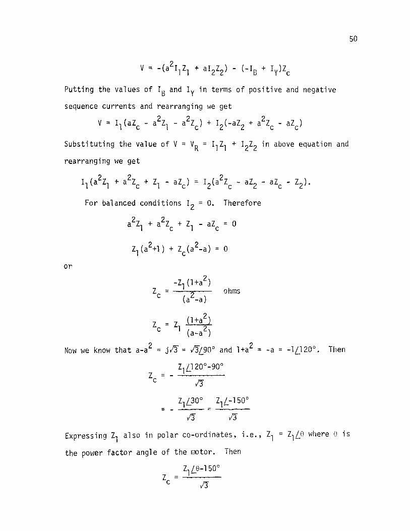
Putting the values of I8 and Iy in terms of positive and negative
sequence currents and rearranging we get
v = I1(aZc- a2z1 - a2zc) + I2(-az2 + a2zc- aZc)
Substituting the value of V = VR = 11z1 + 12z2 in above equation and
rearranging we get
or
For balanced conditions 12 = 0. Therefore
a2z + a2z + z - aZ = o 1 c 1 c
2 -z1 (l+a ) Z = ohms c (a2-a)
Z = Z (l+a2) c 1 (a-a2)
Now we know that a-a2 = j/3 = 13!90° and l+a2 =-a= -1/120°. Then
Z /120°-90° z = - _1.:_-___ _ c jj
z1L-150°
13
50
Expressing zl also in polar co-ordinates, i.e., zl = ZlLe where 8 is
the power factor angle of the motor. Then
z1Le-150° z = _._ __ _ c yj
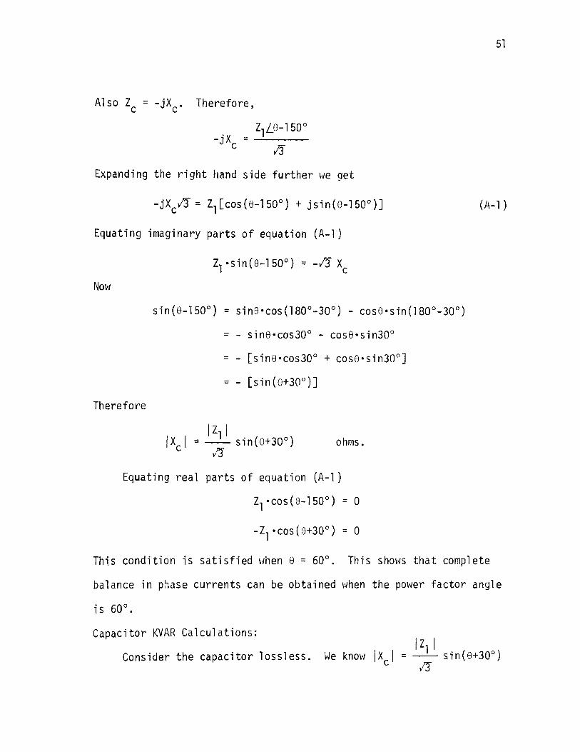
A1so Zc = -jXc. Therefore,
. z1Le-lsoo -JX = ----
c /3
Expanding the right hand side further we get
Equating imaginary parts of equation (A-1)
Now
Therefore
z1 ·sin(e-150°) = -/3 x c
sin8•cos30° - cos8•sin30°
[sin8•cos30° + cose·sin30°]
I z1 1
IX I = -- sin(8+30°) ohms. c yj"
Equating real parts of equation (A-1)
z1 ·cos(e-150°) = 0
-z1 ·cos(e+30°) = o
51
(A-1 )
This condition is satisfied when e = 60°. This shows that complete
balance in phase currents can be obtained when the power factor angle
Capacitor KVAR Calculations:
Consider the capacitor lossless.

or
v'! Jv,l IYcl = sin(8+305 )
Multiplying both sides by v8 2
Now
2 13 IV, I IVBI 2
IYcl IVsl = sin{e+305")
KVAR = KVA of motor l!•sin(8+30°)
52

APPENDIX B
The diagram for the capacitor-reactor type phase converter is
given below:
v
FIG. 17: Capacitor-reactor type phase converter
53
From the above diagram V = VR = -V8 - Vy. In a symmetrical motor,
i.e., when ZR = Zy = z8, IR + I8 + Iy = 0, implying no zero sequence
current. Let r1 and I2 be the positive and negative sequence currents
per phase of the induction motor. Let z1 and z2 be the positive and
negative sequence impedences of the motor per phase at a specified
slip. Therefore
- 2 Iy - a I1 + ai 2
Simi 1 arly

At point A
Similarly:
Therefore:
Putting these values in equation (C-1 ),
and rearranging
[a2ll all 2
Il z- + -l- +a L C
for balanced conditions 12 = 0. Therefore
2 a l 1 al1 2 -z-+-z-+a -a=O
L C
1 (a2 - a) z,
54

55
or 2 2 (a - a) v1 + a YL - aYe = 0 (B-2)
Where:
y = -jB L L
G is the conductance, B is the susceptance, the + sign indicates
capacitive susceptance, and - sign inductive susceptance.
Also we know that a2 - a = -jlr, a2 = -0.5 -j 0.866, and a = - 0.5 +
j 0.866. Putting the values in equation (B-2) we get
-jlr (G1-jB1) + (-0.5-j0.866)(-jBL) - (-0.5+j0.866)jBC = 0
or
Equating real and imaginary parts \ve get the fo11owing two equations.
- /3G1+ 0.5BL + 0.5BC = 0
Adding (B-3) and (B-4) we get
- /JG1 - B1 + 8C = 0
or
Subtracting (B-4) from (B-3) we get (these are absolute values)
(B-3)
(B-4)

Now
Therefore
G1 = Y1·cose
n1 = v1·sine
Be = v1 (/!•case + sine)
Dividing and multiplying by bm, the right hand side of the above
equation
Be= 2Y1(l!/2 case+ l/2 sine)
= 2Y1(cos 30° case+ sin 30° sin e)
56
(B-5)
Simi 1 arly
Capacitor and Reactor KVA Calculations: 2 Nultiplying both sides of equation (B-6) by Vy
YL Vy2 = 2 Y1 Vy2 cos(e+30°)
We know
3 Y 1 V y 2 = KV A of motor
2 YL Vy = Inductive KVA the reactor
Therefore (considering the reactor lossless)
(1)-6)
KVAR (REACTOR) = ~ cos(e+30°). (KVA of motor)
similarly multiplying (B-5) on both sides by v82
Yc v82 = 2 v1 vB2 cos (e-30°)

57
Now
Yc V82 = KVA of capacitor
When the capacitor is lossless = KVAR of capacitor. So
KVAR (CAPACITOR) = ~ cos(e-30°) (KVA of motor)

APPENDIX C
The diagram for the auto-transformer capacitor phase converter
scheme is shown below:
J,
58
I ~--_. A ___ 1..:.1 __ ...a..~B-' -------------_.... B To 3 0
t >- ___ ..,. c motor IB
v,
c ,,
FIG. 18: Auto-transformer capacitor type phase converter
Now from the figure
VA'B' = v A ,8 = rw1
VB'C' = VBC = Vl
VC'A' = VCA' = -(v1+Nv1)
= - ( 1 +N) V 1
\:Jhere r~ is
The positive, negative and zero sequence voltages are given by

VA'B = l/3(V b + aVb + a2v ) 1 a c ca
VA'B = 1/3(V b + a2Vb + aV ) 2 a c ca
VA'B = l/3(V b + Vb + V ) 0 a c ca
Where Vab, Vbc and Vca are voltage phasors. Putting the values
v ab = v A '1:3 = rN l
V be = V BC = Vl
V = -(l+N)V ca l
in equation (C-1) we get 2 2 VA'B = 1/3(NV1 + aV1 - a v1 - a NVl)
1
v = --1 [j + N(0.866+j0.5)]
l3
Similarly equation (C-2) becomes
VA'B ~ l/3(N + a2 - a - aN) v1 2
= 1/3 [(a2-a) + N(l-a)] v1
v, . =-- [-J + N(0.866 - j0.5)]
l3
59
( C-1 )
(C-2)
(C-3)
(C-4)
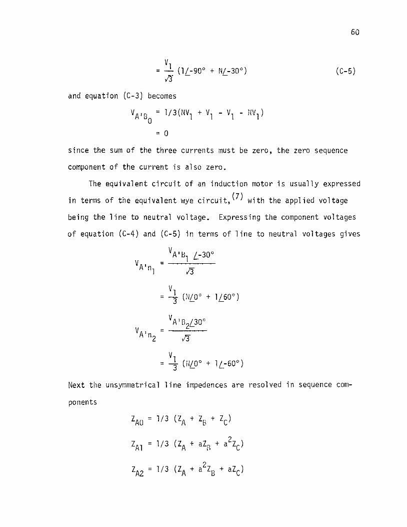
60
(C-5)
and equation (C-3) becomes
VA'B = l/3(NV1 + v1 - v1 - NV1) 0
= 0
since the sum of the three currents must be zero, the zero sequence
component of the current is also zero.
The equivalent circuit of an induction motor is usually expressed
in terms of the equivalent wye circuit,(?) with the applied voltage
being the line to neutral voltage. Expressing the component voltages
of equation (C-4) and (C-5) in terms of line to neutral voltages gives
Next the unsymmetrical line impedences are resolved in sequence com-
ponents
ZAO = 1/3 (ZA + z8 + Zc)
2 ZAl = l/3 (ZA + aZR + a Zc)
2 zA2 = 1/3 (ZA + a z8 + aZC)

61
Where ZA, z8 and Zc are line impedences in the phase converter circuit.
Also
z = z = 0 B C
Thus
The equation of the circuit can now be written(?) as follows
VA ' n 1 = I a 1 ( z A 1 + Zm 1 ) + I a 2 z A2
VA'n = 1al z~1 + Ia2(ZA2 + zm2) 2
(C-6)
(C-7)
vlhere Ial and Ia2 are positive and negative sequence components of
current IA. Zml and zm2 are positive and negative sequence impedence
per phase of the induction motor at a specified slip. Putting the
values of VA'n , VA'n , ZAl and zA2 in equations (C-6) and (C-7) 1 2
~1 (N/0' + lL60') = Ial [~II + zmll + Ia2 ~A (C-8)
(C-9)
For balanced operation of three phase motors the negative sequence
current Ia2 should be zero. Therefore
62
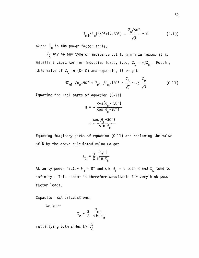
= 0 ( C-1 0)
where em is the power factor angle.
ZA may be any type of impedence but to minimize losses it is
usually a capacitor for inductive loads, i.e., ZA = -jXc. Putting
this value of ZA in (C-10) and expanding it we get
ZA Xc NZ l /e -90° + Z ;e -150° = -- = -j m - m ml - m l! l!
Equating the real parts of equation (C-11)
cos(em-150°) N =- -~~~~ cos(em-906 )
cos(8m+30°) = --.~::---
sin em
(C-11 )
Equating imaginary parts of equation (C-11) and replacing the value
of N by the above ca 1 cul a ted va 1 ue ~1e get
At unity power factor 8 = 0° and sin 8 = 0 both ~~ and XC tend to m m
infinity. This scheme is therefore unsuitable for very high pm>~er
factor loads.
Capacitor KVA Calculations:
\tJe know x = ~ zml c 2 sin em
multiplying both sides by I~

KVA of motor KVA of capacitor = ~---=--:::'---''---2 sin em If the capacitor is lossless
KVAR = KVA of motor 2 sin em
Transformer KVA Calculations:
KVA rating of A1 B1 portion of the winding is
= rN I •l 03 1 A
N = - • KVA of motor
/3
Total KVA of transformer = _gJi •KVA of motor. 13
63
APPENDIX D
HEATING OF GROUND ELECTRODE
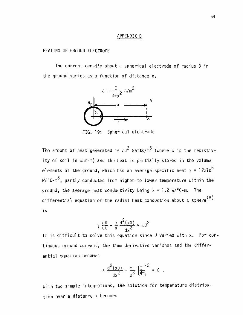
The current density about a spherical electrode of radius B in
the ground varies as a function of distance x,
I 2 J = -:---7 A/ m
4TIX 8 ---.-.4"'
X
FIG. 19: Spherical electrode
64
The amount of heat generated is pJ 2 ~~atts;m3 (vJhere p is the resistiv
ity of soil in ohm-m) and the heat is partially stored in the volume
elements of the ground, which has an average specific heat y = 17xlo6
W/°C-m3, partly conducted from higher to lower temperature within the
ground, the average heat conductivity being A= 1.2 W/°C-m. The
differential equation of the radial heat conduction about a sphere(B)
is
y ~ _ ~ d 2 (X 8 ) = pJ 2 dt x dx2
It is difficult to solve this equation since J varies with x. For con-
tinuous ground current, the time derivative vanishes and the differ-
ential equation becomes
With two simple integrations, the solution for temperature distribu
tion over a distance x becomes
65
e = £. (LJ 2 l [l _ L] oc A 4rr X 8 2x
Then maximum earth temperature at the electrode will be when x = B,
i.e. ,
1 fi J 2 e =- • .f?.. ~ B 2 A L4rru
and depends only on two constants p and A and current density. The
resistance of the spherical electrode of diameter 2B meters (buried in
earth) is
R = 4~B oh111s
then
I = 4rrB J'li!- = 1 /R /2pA8 amps
the voltage of ground electrode is
E = IR = /2pA8 volts.
66
APPENDIX E
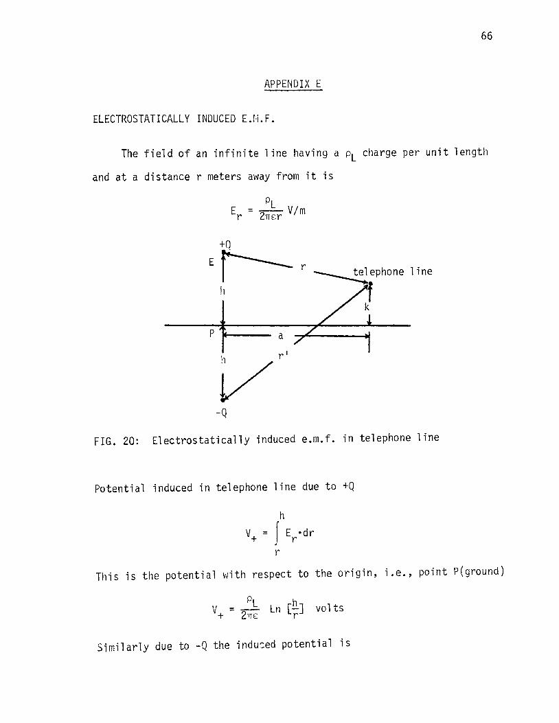
ELECTROSTATICALLY INDUCED E.M.F.
The field of an infinite line having a pl charge per unit length
and at a distance r meters away from it is
Er---r 1 i ne
h
p a
-Q
FIG. 20: Electrostatically induced e.m.f. in telephone line
Potential induced in telephone line due to +Q
This is the potential with respect to the origin, i.e., point P(ground)
PL h V =- ln [-] volts + 2nE r
Similarly due to -Q the indu:ed potential is

67
PL h v = - 21TE Ln rr vo 1 ts
Therefore the total potential difference between the origin and tele
phone line is
V = V + V = - Ln - - Ln -PL [ h h ] + - 21TE r r'
Volts (E-1)
Since the origin is the ground therefore the potential is ~lith respect
to ground.
The voltage E to ground of the high voltage S\~ER line of height
h meters and diameter d meters is as bel O\'J, \'Jhere the electric field
in this case is also the same, i.e., at a distance of r meters
then
d/2
E = - f 2h
2h
E dr = ~ J dr r 21TE r
d/2
val ts
Dividing (E-1) by (E-2) we get
2 = a
r' es _ Ln r E- Ln ill
d
(h-k) 2 = a2 + h2 + k2 - 2hk and
val ts
( E-2)
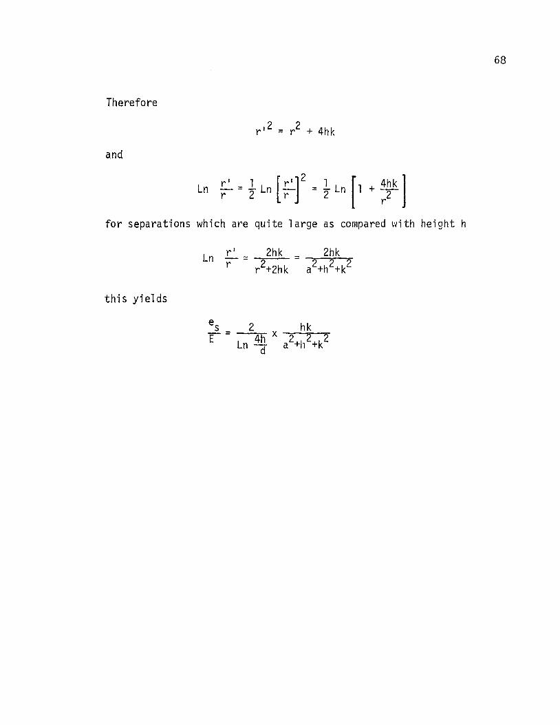
68
Therefore
and
Ln - = - Ln - = - Ln 1 + -r 1 1 [ r 1 ]
2 1 [ 4h k l r 2 r 2 r2
for separations which are quite large as compared ~'lith height h
this yields