An Analysis of Representative Heating Load Lines for ...
60
ORNL/TM-2015/281 An Analysis of Representative Heating Load Lines for Residential HSPF Ratings C. Keith Rice Bo Shen Som S. Shrestha July 2015 Approved for public release. Distribution is unlimited.
Transcript of An Analysis of Representative Heating Load Lines for ...

ORNL/TM-2015/281
An Analysis of Representative Heating Load Lines for Residential HSPF Ratings
C. Keith Rice Bo Shen Som S. Shrestha
July 2015
Approved for public release. Distribution is unlimited.

DOCUMENT AVAILABILITY Reports produced after January 1, 1996, are generally available free via US Department of Energy (DOE) SciTech Connect. Website http://www.osti.gov/scitech/ Reports produced before January 1, 1996, may be purchased by members of the public from the following source: National Technical Information Service 5285 Port Royal Road Springfield, VA 22161 Telephone 703-605-6000 (1-800-553-6847) TDD 703-487-4639 Fax 703-605-6900 E-mail [email protected] Website http://www.ntis.gov/help/ordermethods.aspx Reports are available to DOE employees, DOE contractors, Energy Technology Data Exchange representatives, and International Nuclear Information System representatives from the following source: Office of Scientific and Technical Information PO Box 62 Oak Ridge, TN 37831 Telephone 865-576-8401 Fax 865-576-5728 E-mail [email protected] Website http://www.osti.gov/contact.html
This report was prepared as an account of work sponsored by an agency of the United States Government. Neither the United States Government nor any agency thereof, nor any of their employees, makes any warranty, express or implied, or assumes any legal liability or responsibility for the accuracy, completeness, or usefulness of any information, apparatus, product, or process disclosed, or represents that its use would not infringe privately owned rights. Reference herein to any specific commercial product, process, or service by trade name, trademark, manufacturer, or otherwise, does not necessarily constitute or imply its endorsement, recommendation, or favoring by the United States Government or any agency thereof. The views and opinions of authors expressed herein do not necessarily state or reflect those of the United States Government or any agency thereof.

ORNL/TM-2015/281
Energy and Transportation Science Division Building Technologies Program
AN ANALYSIS OF REPRESENTATIVE HEATING LOAD LINES FOR RESIDENTIAL HSPF RATINGS*
C. Keith Rice Bo Shen
Som S. Shrestha
Date Published: July 2015
Prepared by OAK RIDGE NATIONAL LABORATORY
Oak Ridge, TN 37831-6283 managed by
UT-BATTELLE, LLC for the
US DEPARTMENT OF ENERGY under contract DE-AC05-00OR22725
*Report for DOE Standards Program Related to Residential Central AC and HP Test Procedures and Rulemaking


iii
CONTENTS
LIST OF FIGURES ...................................................................................................................................... v LIST OF TABLES ....................................................................................................................................... vi ACKNOWLEDGMENTS .......................................................................................................................... vii ABBREVIATED TERMS ........................................................................................................................... ix 1. SUMMARY .......................................................................................................................................... 1 2. BACKGROUND AND ISSUES WITH PRESENT HEATING LOAD LINES .................................. 1 3. REPRESENTATIVE LOAD LINES FROM ENERGYPLUS FOR DOE CLIMATE
REGIONS III, IV, AND V ................................................................................................................... 4 3.1 LOAD COMPARISONS IN DOE CLIMATE REGION IV ...................................................... 4 3.2 LOAD COMPARISONS IN DOE CLIMATE REGIONS III AND V ...................................... 9 3.3 ALTERNATIVE HEATING LOAD LINE BASED ON ENERGYPLUS BINNED
LOADS FOR REGION IV LOCATIONS ................................................................................ 11 3.4 COMPARISONS OF ALTERNATIVE HEATING LOAD LINE FOR REGION III
LOCATIONS ............................................................................................................................ 14 3.5 COMPARISONS OF ALTERNATIVE HEATING LOAD LINE FOR REGION V
LOCATIONS ............................................................................................................................ 15 3.6 SUMMARY OF THE ALTERNATIVE HEATING LOAD LINE APPROACH
COMPARED WITH THE CURRENT PROCEDURE ............................................................ 16 3.7 MERITS OF HEATING LOAD LINE BASED ON HOUSE DESIGN COOLING
LOAD ....................................................................................................................................... 19 4. EFFECT OF ALTERNATIVE HEATING LOAD EQUATION ON HSPF RATING VALUES ..... 20
4.1 HSPF EFFECTS FOR SINGLE-CAPACITY UNITS ............................................................. 21 4.2 HSPF EFFECTS FOR TWO-CAPACITY UNITS, STANDARD AND NORTHERN-
CLIMATE APPLICATION ...................................................................................................... 23 4.3 EFFECTS OF RATIO OF Qh(47) TO Qc(95) ON RATED HSPF VALUES .......................... 25
5. CLOSURE .......................................................................................................................................... 28 6. REFERENCES ................................................................................................................................... 29 APPENDIX A. EFFECT OF HOUSE FOUNDATION TYPE, IECC LEVEL, AND CLIMATE
REGION ON ENERGYPLUS HEATING LOAD LINES ............................................................... A-1 APPENDIX B. HEATING LOAD HOURS, SEASONAL HEATING LOADS, AND REGIONAL
HSPF EFFECTS FOR ALTERNATIVE LOAD LINES COMPARED TO AHRI 210/240 ........... B-1

v
LIST OF FIGURES
Figure Page
1 Heating load lines and typical single-speed (steady-state) heat pump capacity vs ambient. ........... 3 2 Hourly rate of total heating delivered for a house in Indianapolis, Indiana, and average
binned load rates. ............................................................................................................................. 5 3 Hourly rate of total cooling delivered for a house in Indianapolis, Indiana, and average
binned load rates. ............................................................................................................................. 5 4 Comparison of EnergyPlus binned cooling load curve and linearization to AHRI load
line. .................................................................................................................................................. 6 5 Comparison of EnergyPlus binned heating load curve and linearization to AHRI min and
max load lines. ................................................................................................................................. 7 6 Comparison of EnergyPlus linearized binned cooling loads to AHRI load line for
Indianapolis, Indiana. ....................................................................................................................... 7 7 Comparison of EnergyPlus linearized binned heating loads to AHRI min and max load
lines for Indianapolis, Indiana. ......................................................................................................... 8 8 Comparison of EnergyPlus linearized binned heating loads to AHRI min and max load
lines for Peoria, Illinois. ................................................................................................................... 8 9 Comparison of EnergyPlus linearized binned heating loads to AHRI min and max load
lines for Philadelphia, Pennsylvania. ............................................................................................... 9 10 Comparison of EnergyPlus linearized binned heating loads to AHRI min and max load
lines for Omaha, Nebraska. .............................................................................................................. 9 11 Comparison of EnergyPlus linearized binned heating loads to AHRI min and max load
lines for Atlanta, Georgia. .............................................................................................................. 10 12 Comparison of EnergyPlus linearized binned heating loads to AHRI min and max load
lines for Oklahoma City, Oklahoma. ............................................................................................. 10 13 Comparison of EnergyPlus linearized binned heating loads to AHRI min and max load
lines for Minneapolis, Minnesota. ................................................................................................. 11 14 Comparison of EnergyPlus linearized binned heating loads to AHRI min and max load
lines for Eagle County, Colorado. .................................................................................................. 11 15 Comparison of the alternative load line with EnergyPlus linearized binned heating loads
and AHRI min and max load lines for Indianapolis, Indiana. ....................................................... 12 16 Comparison of the alternative load line with EnergyPlus linearized binned heating loads
and AHRI min and max load lines for Peoria, Illinois. .................................................................. 12 17 Comparison of the alternative load line to EnergyPlus linearized binned heating loads and
AHRI min and max load lines for Philadelphia, Pennsylvania. ..................................................... 13 18 Comparison of the alternative load line to EnergyPlus linearized binned heating loads and
AHRI min and max load lines for Omaha, Nebraska. ................................................................... 13 19 Comparison of the alternative load line to EnergyPlus linearized binned heating loads and
AHRI min and max load lines for Atlanta, Georgia. ..................................................................... 14 20 Comparison of the alternative load line to EnergyPlus linearized binned heating loads and
AHRI min and max load lines for Oklahoma City, Oklahoma. ..................................................... 15 21 Comparison of the alternative load line to EnergyPlus linearized binned heating loads and
AHRI min and max load lines for Minneapolis, Minnesota. ......................................................... 15 22 Comparison of the alternative load line to EnergyPlus linearized binned heating loads and
AHRI min and max load lines for Eagle County, Colorado. ......................................................... 16 23 Current and alternative heating load lines and single-speed heat pump capacity curve
from ratings test vs ambient, normalized to unit heating capacity at 47°F. ................................... 21
vi
24 Heating performance factors and energy use fractions with the AHRI 210/240 min load line. ................................................................................................................................................ 22
25 Heating performance factors and energy use fractions with the alternative load line. .................. 22 26 Reduction in rated HSPF from alternative heating load line for single- and two-capacity
heat pumps ..................................................................................................................................... 24 27 Range of Qh(47)/Qc(95) ratios for unitary heat pumps in the AHRI certified directory
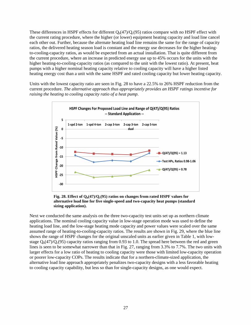
database. ......................................................................................................................................... 26 28 Effect of Qh(47)/Qc(95) ratios on changes from rated HSPF values for alternative load
line for five single-speed and two-capacity heat pumps (standard sizing application). ................. 27 29 Effect of Qh(47)/Qc(95) ratios on changes from rated HSPF values for alternative load
line for three two-capacity heat pumps (northern climate sizing application). .............................. 28
LIST OF TABLES
Table Page
1 HSPF ratings changes using alternative heating load line for different sizing and heat pump types ..................................................................................................................................... 24
2 Relative HSPF ratings changes from standard to northern climate application for current and alternative heating load lines ................................................................................................... 25

vii
ACKNOWLEDGMENTS
This report and the work described were sponsored by the Standards Program within the Building Technologies Office of the US Department of Energy Office of Energy Efficiency and Renewable Energy. The authors wish to acknowledge the contributions of John Cymbalsky and Ashley Armstrong of DOE Standards Program and Patrick Hughes of the ORNL Building Technologies Program in supporting this work and the helpful review comments and team support from Detlef Westphalen and Xing Xu of Navigant and Yi Qu, Greg Rosenquist, Alison Williams, and Bingyi Yu of Lawrence Berkeley National Laboratory.


ix
ABBREVIATED TERMS
AHRI Air-Conditioning, Heating, and Refrigeration Institute ANSI American National Standards Institute ARI Air-Conditioning and Refrigeration Institute COP coefficient of performance DHR design heating requirement DHRmax maximum design heating requirement DHRmin minimum design heating requirement DOE US Department of Energy EPCA Energy Policy and Conservation Act of 1975 ESP external static pressure FSEC Florida Solar Energy Center HLH heating load hour HPF heating performance factor HSPF heating seasonal performance factor IECC International Energy Conservation Code ORNL Oak Ridge National Laboratory PNNL Pacific Northwest National Laboratory SLCF seasonal load change factor


1
1. SUMMARY
This report describes an analysis to investigate representative heating loads for single-family detached homes using current EnergyPlus simulations (DOE 2014a). Hourly delivered load results are used to determine binned load lines using US Department of Energy (DOE) residential prototype building models (DOE 2014b) developed by Pacific Northwest National Laboratory (PNNL). The selected residential single-family prototype buildings are based on the 2006 International Energy Conservation Code (IECC 2006) in the DOE climate regions. The resulting load lines are compared with the American National Standards Institute (ANSI)/Air-Conditioning, Heating, and Refrigeration Institute (AHRI) Standard 210/240 (AHRI 2008) minimum and maximum design heating requirement (DHR) load lines of the heating seasonal performance factor (HSPF) ratings procedure for each region. The results indicate that a heating load line closer to the maximum DHR load line, and with a lower zero load ambient temperature, is more representative of heating loads predicted for EnergyPlus prototype residential buildings than the minimum DHR load line presently used to determine HSPF ratings. An alternative heating load line equation was developed and compared to binned load lines obtained from the EnergyPlus simulation results. The effect on HSPF of the alternative heating load line was evaluated for single-speed and two-capacity heat pumps, and an average HSPF reduction of 16% was found. The alternative heating load line relationship is tied to the rated cooling capacity of the heat pump based on EnergyPlus autosizing, which is more representative of the house load characteristics than the rated heating capacity. The alternative heating load line equation was found to be independent of climate for the six DOE climate regions investigated, provided an adjustable zero load ambient temperature is used. For Region IV, the default DOE climate region used for HSPF ratings, the higher load line results in an ~28% increase in delivered heating load and an ~52% increase in the estimated heating operating cost over that given in the AHRI directory (AHRI 2014).
2. BACKGROUND AND ISSUES WITH PRESENT HEATING LOAD LINES
The Energy Policy and Conservation Act of 1975 (EPCA) requires that “test procedures shall produce energy efficiency or energy use results that are representative of a covered product operating over an average period of use, and shall not be unduly burdensome to conduct.” [42 U.S.C. 6293(b)(3)]
The HSPF rating procedure for residential heat pumps is defined in ANSI/AHRI 210/240 (AHRI 2008). The procedure defines minimum and maximum heating load lines and temperature bin data for DOE climate regions I through VI. The original intent of this approach when developed (Parken et al. 1980) was to provide a means for predicting heating performance for a range of climates and house envelope performance levels. This information would presumably have been provided by the heat pump manufacturers. However, this expectation was not realized; the ratings values are only provided by manufacturers for Region IV using the minimum design heating requirement (DHRmin) load line.
As an alternative to publishing more comprehensive ratings, the AHRI [formerly the Air-Conditioning and Refrigeration Institute (ARI)] directories of certified unitary air-source heat pumps in the 80s and 90s provided an ENERGYGUIDE worksheet (ARI 2000) to assist contractors and homeowners in using the Region IV–rated HSPF values (through the published seasonal operating costs) to predict heating cost adjustment factors for each region, and from those, regional heating costs. The worksheet covered a range of rated unit heating capacities and building heat loss levels. The ENERGYGUIDE worksheet has not been generally available since the ARI directories went online after year 2000. At present, the only method recommended in AHRI 210/240 for calculating annual performance and energy use is in Appendix C, Sects. 4.3.1 and 4.3.2. This method requires the user to define the HSPF consistent with the assumed load line and climate region, using heat pump test data generally available only to the manufacturer. In summary, a calculation approach and/or test data needed to make HSPF calculations for

2
load lines or climate regions other than DHRmin in DOE Region IV are not available for consumers or others interested in making payback or other economic calculations unless provided by the manufacturers. This provision available in AHRI 210/240 has generally not been utilized by the manufacturers to provide such information to consumers, utilities, or other stakeholders. Because ratings information needed for such calculations are not generally available, they are, in contradiction to the requirement in 42 U.S.C. 6293(b)(3), “unduly burdensome to conduct” by the end users, and thus some approximate means of estimating regional HSPF effects and heating energy cost are needed. The ENERGYGUIDE worksheet, which served to meet this need, indicated regional variations in HSPF from +21% in Region I to –13% in Region V, relative to the rated Region IV values, based on the minimum heating load line. However, this worksheet is no longer provided and so only one HSPF rating is available, representing average national performance.
Given that the HSPF rating for residential heat pumps is based on the minimum load line, studies have indicated that the rated HSPF values overestimate actual heating season performance (Erbs et al. 1986, Fairey et al. 2004, Francisco et al. 2004). A Florida Solar Energy Center (FSEC) paper found that HSPF reduction factors of ~30% were needed for DOE Region IV climates to match the heating seasonal performance factors predicted by DOE 2.1E (Fairey et al. 2004). This overestimate of heating seasonal performance is due in significant part to an assumed heating load line for ratings purposes that gives a much lower heating balance point than is typical for properly sized systems. (The heating balance point is the outdoor temperature below which the heat pump is no longer able to meet the required heating load.) Erbs et al. (1986) noted that “the heating load line substantially underestimates the total heating requirements; this directly aids the heat pump since less auxiliary heating is then required, making the HSPF higher than it should be.”
The seasonal performance overestimate is also due in part to an assumed zero load at 65°F ambient. Erbs et al. (1986) noted that the heating balance points were too low in the ratings procedure because (1) the heating load line slope was too low, and (2) the zero load ambient temperature was too high, with a 55°F to 60°F zero load intercept being more typical than 65°F. Fairey et al. (2004) and Francisco et al. (2004) also take issue with the assumed 65°F intercept and the use of a heating load correction factor, C, of 0.77 [attributed to Harris et al. (1965)] in the definition of the ratings load lines; they questioned the suitability of this approach to correct for internal and solar heat gains that lower the heating load. Francisco recommended in 2004 that the appropriate range for the zero load intercept be between 50°F and 60°F ambient temperature due to improved home construction since the Erbs et al. (1986) recommendation of 55°F to 60°F.
The minimum heating load line in DOE Region IV is defined by a straight line from zero load at 65°F ambient temperature to a load at 5°F ambient equal to Qh(47), the rated nominal heating capacity of the heat pump at 47°F ambient, times the 0.77 correction factor. The equation for the minimum load line in Region IV can be written as
Minimum Heating Load (Tj) = Qh(47) * 0.77 * (65-Tj)/60 ,
where Qh(47) = DHRmin in DOE Region IV and Tj is the bin ambient temperature.
This gives a load line matching Qh(47) at –13°F ambient. The maximum load line for DOE Region IV results in a straight line from zero load at 65°F ambient temperature to a load at –13°F ambient equal to twice the value for DHRmin. These relationships are shown in Fig. 1, where normalized DOE Region IV minimum and maximum heating load lines and a typical single-speed heat pump steady-state heating capacity line are plotted against ambient temperature. These load lines also apply for DOE Regions I, II, III, and VI (Pacific Northwest). However, for Region V, the coldest DOE climate region, the minimum load line is 20% lower than those for the other regions, while the maximum load line is 12% lower (the

3
latter due to the use of a 2.2 multiplier rather than 2.0). The reason for this different load line for Region V is not given.
0.0
0.2
0.4
0.6
0.8
1.0
1.2
1.4
1.6
1.8
2.0
-13 -3 7 17 27 37 47 57 67
Heat
ing
Load
and
Cap
acity
/ Q
(47)
Ambient Temperature (F)
AHRI 210/240 Min. and Max. Design Heating Loads Versus Single-Speed Steady-State Equipment Capacity
Region IV Max Load Line
Typical Heat Pump Capacity
Region IV Min (Ratings) Load Line
QH(47) = 1
Fig. 1. Heating load lines and typical single-speed (steady-state) heat pump capacity vs ambient.
In the example shown in Fig. 1, for a single-speed heat pump with a scroll compressor, the balance point below which supplemental resistance heat is required is at ~17°F ambient for the minimum load line. That is much lower than the more typical 26°F to 32°F balance points that result from units sized based on design cooling loads, which is the industry standard practice (ACCA Manual S, 2014). The example shown is for single-speed heat pumps, but the same problem of having DHRmin predict a balance point that is too low exists for two-capacity and variable-speed equipment, although to a lesser extent for northern-climate two-capacity and variable-speed units that have overspeed operation in heating mode.
While the ratings procedure does not explicitly include the common method of using resistance heat as a means to temper the supply air during defrost, the low balance point of ~17°F also excludes any implicit accounting of this energy use. For air-source heat pumps, frosting of the outdoor coil occurs at ambient temperatures from about 17°F to 42°F. Above 42°F, the coil surface temperature remains above the frost point, and below 17°F, the air passing over the coil is too dry to cause significant frost accumulation. Heat pumps are designed to defrost the outdoor coil by reversing operation as needed. Typically, resistance heat is applied in the indoor air handler during defrost to offset the attendant cooling from the indoor coil. When a realistic load line is used, the balance point falls within the frosting range, and any loss in net capacity from the frosting/defrosting cycle at temperatures below the balance point is made up in the HSPF procedure by resistance heat, thereby implicitly including the defrost-tempering energy use. At temperatures above the balance point, there is no accounting for this use of resistance heat, as the capacity loss is made up in the ratings calculation by longer heat pump operation and less cycling loss. Consequently, use of the minimum load line effectively eliminates all defrost-tempering energy use because the entire ambient frosting range is above the 17°F balance point. The omission from the ratings procedure of resistance heat used for defrost-tempering is another significant reason why 30% HSPF reduction factors were needed by Fairey et al. (2004), where defrost tempering heat effects were included, to match realistic values of heating season energy use in Region IV climates. A higher load line with a

4
balance point around 30°F would implicitly include defrost-tempering energy over about half (from 17°F to 30°F) of the frosting ambient interval (from 17°F to 42°F).
This study investigates the use of average binned loads derived from EnergyPlus simulations of DOE residential single-family prototype houses based on 2006 IECC in DOE Regions III, IV, and V (DOE 2014b) as the basis for development of a more realistic heating load line for HSPF ratings, preferably following a similar mathematical form to the current AHRI 210/240 load line representation. A revised load line approach should give a heating balance point closer to field experience and EnergyPlus results for representative houses in regions of the United States where the use of supplemental heat can be significant (i.e., DOE climate regions III, IV, and V, in order of increased resistance-heat use).
3. REPRESENTATIVE LOAD LINES FROM ENERGYPLUS FOR DOE CLIMATE REGIONS III, IV, AND V
Prototype residential house models available for use with EnergyPlus were chosen as the basis for calculating representative house loads for the DOE climate regions III, IV, and V, where the use of supplemental resistance heat can be significant. The house models, developed by PNNL for DOE (Taylor et al. 2012, DOE 2014b), are based on the 2006 IECC prescribed housing characteristic levels. House models are also available for 2009 and 2012 IECC levels, but the 2006 levels were assumed to be the most representative of average US housing stock for some time to come. The single-family houses are rectangular, two-story 30 by 40 ft houses with a total of 2400 ft2 of conditioned space on the main and second floors. The house input data files are selected by foundation type, heating system type, and location. For Region III, a slab foundation was used; in regions IV and V, a conditioned basement was assumed with an additional 1200 ft2 of conditioned space. These selections were made based on the foundation types most commonly found in those regions. The space conditioning system type used for all houses was the air-source heat pump. House thermostat set points were 75°F in cooling season and 70°F in heating season. The online EnergyPlus house data sets are for EnergyPlus version 5 but were converted at Oak Ridge National Laboratory (ORNL) using the standard EnergyPlus conversion tool for compatibility with version 8.1 (DOE 2014a).
Four locations were selected for DOE climate Region IV: Philadelphia, Pennsylvania; Indianapolis, Indiana; Peoria, Illinois; and Omaha, Nebraska. Two locations, Atlanta, Georgia, and Oklahoma City, Oklahoma, were chosen for Region III, and two locations, Minneapolis, Minnesota, and Eagle County, Colorado, were chosen for Region V. The autosizing option in EnergyPlus was used to size the heat pumps to the design cooling load for each house and location.
Once the house/location files were selected, EnergyPlus simulations with a 15 minute time step (default time step used in DOE residential prototype building models) were run for an autosized heat pump to obtain delivered hourly cooling and heating loads over a full year. In the case of delivered cooling loads, they were total (sensible plus latent) values. The loads were imported to a spreadsheet template, plotted vs ambient temperature, and binned into the same 5°F ambient bins used in the AHRI 210/240 ratings procedure.
3.1 LOAD COMPARISONS IN DOE CLIMATE REGION IV
The hourly total heating load rates and the average binned values for Indianapolis, a DOE Climate Region IV location, are shown in Fig. 2. The delivered total cooling load rates and binned values are shown in Fig. 3. From Figs. 2 and 3, the binned load values are seen to give a reasonable average representation of the range of delivered hourly loads.

5
0
2000
4000
6000
8000
10000
12000
14000
-13 -3 7 17 27 37 47 57 67 77
Deliv
ered
Loa
d Ra
te (W
)
Ambient Temp [F]
Total Heating Load Rate (W)
Hourly Heating Load Rate (W)
Binned Load Rate (W)
Fig. 2. Hourly rate of total heating delivered for a house in Indianapolis, Indiana, and average binned load rates.
0
1000
2000
3000
4000
5000
6000
7000
8000
9000
10000
52 57 62 67 72 77 82 87 92 97 102
Deliv
ered
Loa
d Ra
te (W
)
Ambient Temp [F]
Total Cooling Load Rate (W)
Hourly Cooling Load Rate (W)
Binned Load Rate (W)
Fig. 3. Hourly rate of total cooling delivered for a house in Indianapolis, Indiana, and average binned load rates.
Next, the binned load line is compared to the AHRI 210/240 load lines per the rating procedure. Using the autosized design cooling size (2.3 tons for Indianapolis), we first compare the cooling load line per 210/240 to the binned cooling load curve and a linearization of the binned load curve. Here we dropped bins with loads that were less than 2% of nominal capacity to improve the R2 correlation for the overall linear curve fit. In Fig. 4, the cooling unit size is shown by the blue diamond, the AHRI load line by the

6
red line, the binned load curve by a purple line, and the linearization by the thin black line and linear curve fit equation and associated R2 value. For this Region IV location, the binned cooling load curve and linearization match fairly well with slightly higher average loads over the ambient range. The zero load point from EnergyPlus for Indianapolis for the linear curve fit is ~62°F compared to the 65°F value assumed in AHRI 210/240. However, the E+ binned loads shown in Fig. 4 are for a 75°F indoor set point while the AHRI 210/240 cooling load line is presumably for the 80°F indoor set point used for the cooling rating point tests. Had this case been run with an 80°F indoor setting, the E+ cooling load line would be ~10% lower and the zero load ambient ~5°F higher. The load line for an 80°F indoor set point when multiplied by 1.1 per AHRI 210/240 gives a 2.21 ton cooling size, which closely matches the E+ autosized unit cooling capacity.
y = 0.8155x - 50.908R² = 0.9892
0
5
10
15
20
25
30
35
52 57 62 67 72 77 82 87 92 97 102
Cool
ing
Load
(kBt
u/h)
Ambient (F)
E+ Cooling Loads Compared to AHRI 210/240 Values
Design Size
AHRI Load
E+ Binned Loads
Linear (E+ Binned Loads)
DOE Region IVIndianapolis, IN
Fig. 4. Comparison of EnergyPlus binned cooling load curve and linearization to AHRI load line.
In Fig. 5, a similar set of plots are shown for heating mode but with AHRI load lines included for both minimum and maximum DHRs. Again we dropped bins with loads that were less than 2% of nominal capacity to improve the R2 correlation for the overall curve fit. Here the indoor set point is 70°F, the same as for the AHRI load lines and equipment test conditions. The AHRI load lines drawn in this study are based on the assumption that the nominal unit heating capacity at 47°F, Qh(47), is equal to the nominal unit cooling capacity at 95°F, Qc(95). This assumption is a close approximation for some units and makes the load lines independent of a particular unit’s Qh(47)/Qc(95) ratio. Also, for this comparison to EnergyPlus binned loads, we did not round the DHRmin and DHRmax values to the nearest 5000 Btu/h values per the rating procedure to avoid the arbitrary effects of such rounding (which is dependent on what the design cooling capacity happens to be for each climate) on the comparisons. For Indianapolis, the binned loads and the linearization are in quite close agreement over the ambient range. The average zero load ambient for the linearized curve fit is seen to be just above 55°F, compared to the 65°F value assumed in AHRI 210/240. Compared to the minimum load line, the binned load line is about the same at 47°F ambient but with a steeper negative slope, with a load multiplier of ~1.6 at 17°F and higher at lower ambients.

7
y = -0.7182x + 40.115R² = 0.9957
0
10
20
30
40
50
60
-13 -3 7 17 27 37 47 57 67
Heat
ing
Load
(kBt
u/h)
Ambient (F)
E+ Heating Loads Compared to AHRI 210/240 Min/Max Values
AHRI Max
E+ Binned Loads
AHRI Min
Linear (E+ Binned Loads)
DOE Region IVIndianapolis, IN
Fig. 5. Comparison of EnergyPlus binned heating load curve and linearization to AHRI min and max load lines.
In Figs. 6 and 7, we show the same plots as in Figs. 4 and 5, but with the linear representation only for the EnergyPlus binned loads.
0
5
10
15
20
25
30
35
52 57 62 67 72 77 82 87 92 97 102
Cool
ing
Load
(kBt
u/h)
Ambient (F)
E+ Cooling Loads Compared to AHRI 210/240 Values
Design Size
AHRI Load
E+ Avg. Load Line
DOE Region IVIndianapolis, IN
Fig. 6. Comparison of EnergyPlus linearized binned cooling loads to AHRI load line for Indianapolis, Indiana.

8
0
10
20
30
40
50
60
-13 -3 7 17 27 37 47 57 67
Heat
ing
Load
(kBt
u/h)
Ambient (F)
E+ Heating Loads Compared to AHRI 210/240 Min/Max Values
AHRI Max Load
E+ Avg. Load Line
AHRI Min Load
DOE Region IVIndianapolis, IN
Fig. 7. Comparison of EnergyPlus linearized binned heating loads to AHRI min and max load lines for Indianapolis, Indiana.
Similar load binnings and linearizations were done for the three other selected DOE Climate Region IV locations of Peoria, Illinois; Philadelphia, Pennsylvania; and Omaha, Nebraska. Plots for the three locations follow in Figs. 8, 9, and 10 for heating load comparisons to AHRI 210/240 min and max DHR load lines. The shape of the original binned load curves for heating and cooling relative to the linearized curve fits for these other Region IV locations were quite similar to that shown for Indianapolis. The cooling load line comparisons to the AHRI load lines were also quite similar for all the cases.
0
10
20
30
40
50
60
-13 -3 7 17 27 37 47 57 67
Hea
ting
Load
(kBt
u/h)
Ambient (F)
E+ Heating Loads Compared to AHRI 210/240 Min/Max Values
AHRI Max Load
E+ Avg. Load Line
AHRI Min Load
DOE Region IVPeoria, IL
Fig. 8. Comparison of EnergyPlus linearized binned heating loads to AHRI min and max load lines for Peoria, Illinois.

9
0
10
20
30
40
50
60
-13 -3 7 17 27 37 47 57 67
Heat
ing
Load
(kBt
u/h)
Ambient (F)
E+ Heating Loads Compared to AHRI 210/240 Min/Max Values
AHRI Max Load
E+ Avg. Load Line
AHRI Min Load
DOE Region IVPhiladelphia, PA
Fig. 9. Comparison of EnergyPlus linearized binned heating loads to AHRI min and max load lines for Philadelphia, Pennsylvania.
0
10
20
30
40
50
60
-13 -3 7 17 27 37 47 57 67
Heat
ing
Load
(kBt
u/h)
Ambient (F)
E+ Heating Loads Compared to AHRI 210/240 Min/Max Values
AHRI Max Load
E+ Avg. Load Line
AHRI Min Load
DOE Region IVOmaha, NE
Fig. 10. Comparison of EnergyPlus linearized binned heating loads to AHRI min and max load lines for Omaha, Nebraska.
3.2 LOAD COMPARISONS IN DOE CLIMATE REGIONS III AND V
Results for two locations each in DOE regions III and V follow. Figures 11 and 12 give the comparisons for the milder heating season climates of Atlanta, Georgia, and Oklahoma City, Oklahoma. The EnergyPlus delivered loads in these locations are as close as or closer to the maximum AHRI load lines as in the colder Region IV climate.

10
0
10
20
30
40
50
60
70
-13 -3 7 17 27 37 47 57 67
Hea
ting
Loa
d (k
Btu/
h)
Ambient (F)
E+ Heating Loads Compared to AHRI 210/240 Min/Max Values
AHRI Max Load
E+ Avg. Load Line
AHRI Min Load
DOE Region IIIAtlanta, GA
Fig. 11. Comparison of EnergyPlus linearized binned heating loads to AHRI min and max load lines for Atlanta, Georgia.
0
10
20
30
40
50
60
70
-13 -3 7 17 27 37 47 57 67
Hea
ting
Load
(kBt
u/h)
Ambient (F)
E+ Heating Loads Compared to AHRI 210/240 Min/Max Values
AHRI Max Load
E+ Avg. Load Line
AHRI Min Load
DOE Region IIIOklahoma City, OK
Fig. 12. Comparison of EnergyPlus linearized binned heating loads to AHRI min and max load lines for Oklahoma City, Oklahoma.
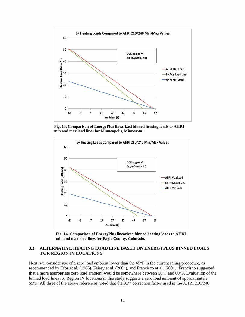
Figures 13 and 14 show the load comparison results for the two DOE Climate Region V locations of Minneapolis, Minnesota, and Eagle County, Colorado. The EnergyPlus heating load line for Minneapolis in Fig. 13 is a bit closer to the max AHRI 210/240 load line than the EnergyPlus heating load lines of the Region IV cases; this is true even though the maximum load line in the special case of Region V is 2.2 times the minimum load line per the AHRI ratings procedure rather than twice as large. The heating load line for Eagle County, Colorado (west of Denver), as shown in Fig. 14, has a similar comparison to the min and max load lines. For both locations the linearized best fit curve gives zero load ambients at or below~55°F.
11
0
10
20
30
40
50
60
-13 -3 7 17 27 37 47 57 67
Hea
ting
Loa
d (k
Btu
/h)
Ambient (F)
E+ Heating Loads Compared to AHRI 210/240 Min/Max Values
AHRI Max Load
E+ Avg. Load Line
AHRI Min Load
DOE Region VMinneapolis, MN
Fig. 13. Comparison of EnergyPlus linearized binned heating loads to AHRI min and max load lines for Minneapolis, Minnesota.
0
10
20
30
40
50
60
-13 -3 7 17 27 37 47 57 67
Hea
ting
Loa
d (k
Btu
/h)
Ambient (F)
E+ Heating Loads Compared to AHRI 210/240 Min/Max Values
AHRI Max Load
E+ Avg. Load Line
AHRI Min Load
DOE Region VEagle County, CO
Fig. 14. Comparison of EnergyPlus linearized binned heating loads to AHRI min and max load lines for Eagle County, Colorado.
3.3 ALTERNATIVE HEATING LOAD LINE BASED ON ENERGYPLUS BINNED LOADS FOR REGION IV LOCATIONS
Next, we consider use of a zero load ambient lower than the 65°F in the current rating procedure, as recommended by Erbs et al. (1986), Fairey et al. (2004), and Francisco et al. (2004). Francisco suggested that a more appropriate zero load ambient would be somewhere between 50°F and 60°F. Evaluation of the binned load lines for Region IV locations in this study suggests a zero load ambient of approximately 55°F. All three of the above references noted that the 0.77 correction factor used in the AHRI 210/240

12
load line equations was applied mainly to account for the effects of an artificially high balance point on the total seasonal heating load. We investigated use of 55°F instead of 65°F as the zero load ambient, as well as a higher slope factor of 1.3 to provide a close match to the linearized heating load lines in Indianapolis, Indiana, and Peoria, Illinois. This alternative heating load line is shown as a dashed line in Fig. 15 for comparison with the EnergyPlus average load line for Indianapolis and the AHRI min and max load lines. A similar comparison is shown in Fig. 16 for Peoria.
0
10
20
30
40
50
60
-13 -3 7 17 27 37 47 57 67
Hea
ting
Loa
d (k
Btu
/h)
Ambient (F)
E+ Heating Loads Compared to AHRI 210/240 Min/Max Values
AHRI Max Load
E+ Avg. Load Line
Alternative Load Line
AHRI Min Load
DOE Region IVIndianapolis, IN
Fig. 15. Comparison of the alternative load line with EnergyPlus linearized binned heating loads and AHRI min and max load lines for Indianapolis, Indiana.
0
10
20
30
40
50
60
-13 -3 7 17 27 37 47 57 67
Hea
tin
g Lo
ad (
kBtu
/h)
Ambient (F)
E+ Heating Loads Compared to AHRI 210/240 Min/Max Values
AHRI Max Load
E+ Avg. Load Line
Alternative Load Line
AHRI Min Load
DOE Region IVPeoria, IL
Fig. 16. Comparison of the alternative load line with EnergyPlus linearized binned heating loads and AHRI min and max load lines for Peoria, Illinois.
13
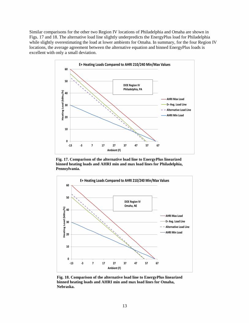
Similar comparisons for the other two Region IV locations of Philadelphia and Omaha are shown in Figs. 17 and 18. The alternative load line slightly underpredicts the EnergyPlus load for Philadelphia while slightly overestimating the load at lower ambients for Omaha. In summary, for the four Region IV locations, the average agreement between the alternative equation and binned EnergyPlus loads is excellent with only a small deviation.
0
10
20
30
40
50
60
-13 -3 7 17 27 37 47 57 67
Hea
tin
g Lo
ad (
kBtu
/h)
Ambient (F)
E+ Heating Loads Compared to AHRI 210/240 Min/Max Values
AHRI Max Load
E+ Avg. Load Line
Alternative Load Line
AHRI Min Load
DOE Region IVPhiladelphia, PA
Fig. 17. Comparison of the alternative load line to EnergyPlus linearized binned heating loads and AHRI min and max load lines for Philadelphia, Pennsylvania.
0
10
20
30
40
50
60
-13 -3 7 17 27 37 47 57 67
Hea
tin
g Lo
ad (
kBtu
/h)
Ambient (F)
E+ Heating Loads Compared to AHRI 210/240 Min/Max Values
AHRI Max Load
E+ Avg. Load Line
Alternative Load Line
AHRI Min Load
DOE Region IVOmaha, NE
Fig. 18. Comparison of the alternative load line to EnergyPlus linearized binned heating loads and AHRI min and max load lines for Omaha, Nebraska.

14
We also looked at the effects of three house foundation types other than heated basement on the predicted EnergyPlus heating loads in Indianapolis based on 2006 IECC. The foundation types were unheated basement, slab, and crawl space. Load comparison results vs the alternative load line equation for these cases are shown in Appendix A. The summary result is that the alternative equation also matched quite well for these cases, underpredicting those loads a bit more than for the heated basement case. As such, the alternative load line is slightly conservative for these other foundation types. Load lines for 2009 and 2012 IECC house performance levels for the DOE Region IV Indianapolis location are also given in Appendix A as well as a summary table of all the considered house types, locations, and code levels, along with the EnergyPlus autosized cooling capacities.
3.4 COMPARISONS OF ALTERNATIVE HEATING LOAD LINE FOR REGION III LOCATIONS
In Figs. 19 and 20, load line comparisons are made for the Region III locations of Atlanta and Oklahoma City. The alternative load line modestly underpredicts the binned loads in Atlanta by an increasing amount at lower ambients while showing a more uniform slight underprediction for Oklahoma City.
0
10
20
30
40
50
60
70
-13 -3 7 17 27 37 47 57 67
Hea
tin
g Lo
ad (
kBtu
/h)
Ambient (F)
E+ Heating Loads Compared to AHRI 210/240 Min/Max Values
AHRI Max Load
E+ Avg. Load Line
Alternative Load Line
AHRI Min Load
DOE Region IIIAtlanta, GA
Fig. 19. Comparison of the alternative load line to EnergyPlus linearized binned heating loads and AHRI min and max load lines for Atlanta, Georgia.

15
0
10
20
30
40
50
60
70
-13 -3 7 17 27 37 47 57 67
Hea
tin
g Lo
ad (k
Btu
/h)
Ambient (F)
E+ Heating Loads Compared to AHRI 210/240 Min/Max Values
AHRI Max Load
E+ Avg. Load Line
Alternative Load Line
AHRI Min Load
DOE Region IIIOklahoma City, OK
Fig. 20. Comparison of the alternative load line to EnergyPlus linearized binned heating loads and AHRI min and max load lines for Oklahoma City, Oklahoma.
3.5 COMPARISONS OF ALTERNATIVE HEATING LOAD LINE FOR REGION V LOCATIONS
Comparisons with the alternative load line for the DOE Region V locations of Minneapolis and Eagle County are given in Figs. 21 and 22. In Fig. 21, agreement is quite close for Minneapolis, where the zero load ambient is slightly lower than 55°F. In Fig. 22, for Eagle County, the zero load ambient is below 50°F, and the load line has a somewhat steeper slope. The alternative line overestimates the binned loads to a decreasing extent at lower ambients.
0
10
20
30
40
50
60
-13 -3 7 17 27 37 47 57 67
Hea
ting
Loa
d (k
Btu/
h)
Ambient (F)
E+ Heating Loads Compared to AHRI 210/240 Min/Max Values
AHRI Max Load
E+ Avg. Load Line
Alternative Load Line
AHRI Min Load
DOE Region VMinneapolis, MN
Fig. 21. Comparison of the alternative load line to EnergyPlus linearized binned heating loads and AHRI min and max load lines for Minneapolis, Minnesota.

16
0
10
20
30
40
50
60
-13 -3 7 17 27 37 47 57 67
Hea
ting
Loa
d (k
Btu/
h)
Ambient (F)
E+ Heating Loads Compared to AHRI 210/240 Min/Max Values
AHRI Max Load
E+ Avg. Load Line
Alternative Load Line
AHRI Min Load
DOE Region VEagle County, CO
Fig. 22. Comparison of the alternative load line to EnergyPlus linearized binned heating loads and AHRI min and max load lines for Eagle County, Colorado.
3.6 SUMMARY OF THE ALTERNATIVE HEATING LOAD LINE APPROACH COMPARED WITH THE CURRENT PROCEDURE
Overall, the agreement of EnergyPlus binned loads with the alternative load line is reasonable for all three DOE climate regions considered, and quite close for the four Region IV locations evaluated. The agreement with the current AHRI minimum load values at 47°F ambient is close as well; the differences increase at the lower ambients. This means that the basis for the cyclic testing tied to 47°F ambient for single- and two-capacity heat pumps should not be affected by a change to the alternative heating load line for single- and two-capacity heat pumps. However, for variable-speed units, the current cyclic test at 62°F could be replaced by a cyclic test at 47°F to be more consistent with the 55°F zero load ambient of the alternative load line.
In summary, the heating load line alternative found to give a close match with the EnergyPlus average load lines for regions III, IV, and V is
Heating Load (Tj) = Qc(95) * 1.3 * (55 – Tj)/50 ,
where Tj is the bin midpoint temperature rounded down to an integer, starting at 52ºF and decreasing in 5°F increments, and Qc(95) is the rated cooling capacity of the heat pump at 95°F ambient. (The suitability of this alternative load line was also investigated in this study for the warmer DOE climate regions I and II and the marine climate of Region VI; it was found to be applicable for those climates if a zero load ambient customized to climate region is included in the alternative approach, as is discussed later in this section.) From this analysis, no need was found for using a different equation giving a lower load line in any of the DOE climate regions considered (III, IV, and V). The small discrepancies seen from this single equation were for specific cities, not by region. The alternative heating load line equation has a similar form to the current AHRI minimum DHR load line equation for all DOE regions other than Region V, shown immediately below:
Heating Load (Tj) = Qh(47) * 0.77 * (65 – Tj)/60 ,
17
as well as for Region V,
Heating Load (Tj) = Qh(47) * 0.77*(65 – Tj)/75 .
In this alternative approach, the seasonal heating load would be calculated by
Qh_seasonal_alt = HLH_55 * DHR_55
where
HLH_55 = 24 * D-D_55/(55 – T_d),
D-D_55= Total Heating Hours / 24 * ∑ fractional bin-hours * (55-Tj)
DHR_55 = (55-T_d)/50 * 1.3 * Qc(95), and
T_d is the heating design temperature.
D-D_55 is the number of heating degree-days below 55°F as compared to the current D-D_65 defined by degree days below 65°F. Similarly, HLH_55 is the number of heating load hours (HLHs) below 55°F as compared to the current HLH_65 values used in AHRI 210/240.
It follows that the alternative seasonal heating load can also be given by
Qh_seasonal_alt = 24 * D-D_55 * 1.3* Qc(95)/50 .
This set of equations compares to the present 210/240 representation of
Qh_seasonal_current = HLH_65 * 0.77 * DHR_65 ,
where
HLH_65 = 24 * D-D_65/(65 – T_d),
D-D_65= Total Heating Hours / 24. * ∑ fractional bin-hours * (65-Tj),
DHR_65 = (65-T_d)/60 * Qh(47) for DOE climate regions I through IV and VI, and
DHR_65 = Qh(47) for DOE climate region V
It follows that the current seasonal heating load for DOE regions other than Region V can also be given by
Q h_seasonal_current = 24 * D-D_65 * 0.77 * Qh(47)/60
and in Region V by
Qh_seasonal_current = 24 * D-D_65 * 0.77* Qh(47)/75 .
Hence, the alternative seasonal heating load equation is shown to have a similar form to the current AHRI seasonal heating load equations.

18
The new calculation approach matches the EnergyPlus delivered seasonal heating load for the DOE Region IV location of Indianapolis to within –5.6%.
An alternative set of heating load hours are given in Appendix B for the 55°F zero ambient load line. These were derived from the present HLH_65 values and fractional bin-hours distribution table in AHRI 210/240. Using these modified values for Region IV with the above alternative seasonal heating load equations, the increase in delivered seasonal heating load in Region IV is 27.6% for a Qh(47)/Qc(95) ratio of 1. This is the seasonal load increase for DOE Region IV with the alternative load line and HLH_55 values.
For DOE Region V, the new calculation approach matches the EnergyPlus delivered seasonal heating load in Minneapolis to within 1.2%. Using the ratio of HLH values for Region V in Appendix B, the increase in delivered seasonal heating load in Region V is 75.7% for a Qh(47)/Qc(95) ratio of 1. The seasonal load increase is larger in Region V than in Region IV because, unlike with the current rating procedure, we are no longer using a “special case” lower load line in Region V compared to the other DOE climate regions.
Accordingly, if the alternative load line with zero load ambient of 55°F were to be adopted in the AHRI 210/240 energy use procedure, the default values of HLHs for each of the DOE climate regions should be replaced by an alternative table given in Appendix B. The fractional bin-hours distribution would not need to be changed. (This would involve changes to the HLH values in Tables 17 and 19 and Fig. 2 on pages 100 and 116 of AHRI 210/240.)
While the 55°F zero load ambient has been shown to be a suitable average value for Regions III, IV, and V from the EnergyPlus analyses for the selected prototype houses, further analysis for appropriate house types in DOE climate regions I, II, and VI, as shown in Appendix A, indicates that slightly higher zero load ambients are a better match in those cases. Regions I and II are the warmest and next-warmest US climates, and Region VI is a marine climate that is mild-ambient heating dominated. (The same slope multiplier of 1.3 was found to still be an acceptable average value for these climates.) The zero load ambients found for the Region I, II, and VI climates were 60°F, 58°F, and 58°F, respectively. In addition, a close inspection of Figs. 19 and 20 indicates that a 57°F zero load ambient is a better match for Region III than 55°F. While these changes in zero load ambient do shift the alternative load lines by only a small amount, because of the large number of hours in these mild ambient bins for these climates, the effect on improving agreement with the calculated EnergyPlus seasonal loads is significant. The increase in calculated mild ambient loads in these warmer climates also appropriately increases the HSPF values calculated for those regions, relative to a fixed 55°F zero load ambient, as shown in Appendix B. Also in that appendix, a second alternative HLH table is provided for use for a load line with the zero load ambient varying by region. This set of HLH values provides the most accurate loads representation compared to the EnergyPlus analyses conducted in this study. With this modified approach, the alternative load line would be given as follows.
Heating Load (Tj) = Qc(95) * 1.3 * (T_zl – Tj)/(T_zl – 5)
and
Qh_seasonal_alt = HLH_vz * DHR_vz
where
T_zl is the zero load temperature,

19
HLH_vz = 24 * D-D_vz/(T_zl – T_d),
D-D_vz= Total Heating Hours / 24 * ∑ fractional bin-hours * (T_zl -Tj), and
DHR_vz = (T_zl - T_d)/(T_zl – 5)* 1.3 * Qc(95),
Similarly, the seasonal heating load can also be rewritten as
Qh_seasonal_alt = 24 * D-D_vz* 1.3* Qc(95)/(T_zl – 5).
Appendix B also includes comparison plots for DOE Regions I, II, and VI of the binned EnergyPlus load lines and alternative load lines with the variable T_zl values noted earlier vs the current min and max AHRI 210/240 load lines.
In summary, the alternative heating load line with a zero load base of 55°F gives a reasonably close approximation to EnergyPlus load lines for all six DOE climate regions used in AHRI 210/240. With suitably modified base 55°F heating load hours, as given in Appendix B, this approach also gives close agreement with EnergyPlus seasonal heating loads for Region IV and V. Similarly close agreement with EnergyPlus seasonal heating loads can also be obtained for Regions I, II, III, and VI if the zero load ambients for those regions are increased to 60, 58, 57, and 58°F, respectively. Appropriate heating load hours for this variable-zero-load ambient approach are also given in Appendix B and comparisons made of the regional seasonal loads and relative HSPF effects for the two approaches.
3.7 MERITS OF HEATING LOAD LINE BASED ON HOUSE DESIGN COOLING LOAD
In this analysis, an alternative heating load line has been shown to be well represented by an equation based on the EnergyPlus autosized design cooling capacity, Qc(95), which in turn was shown to match up closely to the house design cooling load with a typical cooling set point. The rated cooling capacity, by the accepted equipment sizing assumption in EnergyPlus, is tied closely to the housing characteristics (e.g., insulation levels, airtightness, window/wall ratio), which in turn determine house space-conditioning loads for both cooling and heating seasons, as has been shown here for all DOE regions.
The AHRI 210/240 procedure uses the nominal heating capacity of the particular heat pump unit at 47°F, rather than the design cooling capacity, to define the heating load line. This results in a so-called “rubber house,” in which the heating load is tied to the heating capacity [Qh(47)] of the unit and the cooling load is tied to the cooling capacity [Qc(95)] of the unit. In reality, heat pumps are generally sized to provide the needed cooling capacity at design conditions, heating and cooling loads tie to each other through housing characteristics, heating and cooling capacities tie to each other through heat pump characteristics, and generally heat pump heating capacity falls short of heating load under some ambient conditions. Two-capacity and variable-speed units exist, in part, to overcome the conundrum of having to size on cooling and take what you can get from the heat pump in heating, with supplemental electric resistance heat used to cover the shortfall. It is more appropriate for the heating loads for HSPF calculations to be tied to the unit’s cooling capacity because this enables HSPF ratings to reflect realistic heating performance differences between single-capacity, two-capacity, and variable-speed units.
In the current HSPF rating approach, a heat pump having a higher nominal heating capacity [Qh(47)] but the same design cooling capacity [Qc(95)] has the same HSPF rating as a unit with a lower nominal heating capacity. This is because the heating load line increases in the same proportion as the equipment heating capacity, giving the same balance points as a unit with lower rated heating capacity. However, in field operation a heat pump with more heating capacity in relation to cooling capacity would have a lower balance point and thus use less energy, since it would satisfy more of the seasonal heating load using heat

20
pump mode as opposed to electric resistance heating. Such a heat pump merits a higher HSPF but is rated the same, effectively being penalized in the current procedure. In addition, the assumed higher heating load line for the unit with higher relative heating capacity results in higher seasonal heating load. The net effect is that over the range of nominal heating to cooling capacity ratios of current equipment, the heating energy use and cost calculated by the AHRI 210/240 procedure can be increased by up to 45% from the lowest to the highest relative heating capacity cases.
A more consistent approach is instead to use the Qc(95) value rather than Qh(47) to determine the heating load line, so that improved heating capacity can be properly reflected as a higher HSPF rating and lower seasonal heating cost. The effect of this difference in heating load line definition on HSPF will be examined in greater detail later in Sect. 4.3..
For northern climate two-capacity heat pumps or variable-speed units with overspeed capability in heating mode, proper sizing for cooling would involve use of the Qc(95) value at the low stage or maximum cooling speed, respectively, instead of the corresponding Qh(47) value.
Adoption of the approach to use Qc(95) rather than Qh(47) for the heating load line would also make irrelevant the rounding of the Qh(47) values in AHRI 210/240 to the nearest 5000, 10,000, or 20,000 Btu/h values as given in Table 18 of AHRI 210/240, depending on the capacity. This would remove another artificial effect on HSPF calculations. In the original method of testing and rating for heat pumps (Parken et al. 1980) up to the current use in AHRI 210/240 in Appendix C, Sects. 4.3.1 and 4.3.2 and Table 18, the rounding is used to allow a table to be made of estimated energy cost for different defined levels of DHRs using HSPFs specific to those different levels. This dated approach follows the one used for furnaces as described earlier by Kelly et al. (1978). (In contrast to furnaces, heat pump heating capacities cannot be selected independently of the unit’s cooling capacity.) It appears that these tables were never, or at least are no longer, provided by the manufacturers, which begs the question—why retain the rounding? With the adoption of a single, more representative heating load line, it would seem that there would no longer be any purpose for such rounding of DHRmin and DHRmax values and the artificial effects that this has on HSPF ratings.
The next section evaluates the effect on the rated HSPF in DOE Region IV for single- and two-capacity heat pumps using the alternative load line with a 55°F zero load ambient and a 1.3 multiplier in place of the present 65°F zero load ambient and 0.77 correction factor.
4. EFFECT OF ALTERNATIVE HEATING LOAD EQUATION ON HSPF RATING VALUES
In this section we evaluate the effect of the alternative load line on rated HSPF. The zero load ambient is set at 55°F and a 1.3 slope factor is used in place of the 0.77 correction factor. Also, Qc(95) is used instead of Qh(47). The alternative load line, as well as the AHRI 210/240 min and max loads, are shown in Fig. 23 along with a heat pump capacity curve generated from test data per the ratings procedure. All load and capacity lines are normalized to Qh(47). From Fig. 23, it can be seen that using the alternative load line gives a balance point of ~29.5°F for the test data as compared with ~16.7°F for the current ratings (minimum) load line.

21
0.0
0.2
0.4
0.6
0.8
1.0
1.2
1.4
1.6
1.8
2.0
-13 -8 -3 2 7 12 17 22 27 32 37 42 47 52 57 62 67
Load
or C
apac
ity /
Q(4
7)
Ambient (F)
Current and Proposed Heating Load Lines Versus Test Unit Capacity
Capacity/Q(47) Proposed Load/Q(47)210/240 Min Load/Q(47)210/240 Max Load/Q(47)
Fig. 23. Current and alternative heating load lines and single-speed heat pump capacity curve from ratings test vs ambient, normalized to unit heating capacity at 47°F.
4.1 HSPF EFFECTS FOR SINGLE-CAPACITY UNITS
In Figs. 24 and 25, the heating performance factors [HPF = coefficient of performance (COP) × 3.412] for each evaluated temperature bin as well as the calculated HSPFs are shown, as determined for the AHRI 210/240 minimum load line and the alternative load line, respectively. With the alternative load line used for Fig. 25, the calculated HSPF value is 6.97 as compared to the 210/240 rated 8.50 value of Fig. 24, a drop of 18.0%. The lower HSPF is seen in Fig. 25 to be the result of a dropoff in net HPF values below the 29.5°F balance point. Also, for both load lines, the HPF values at 47°F ambient are very close to each other because the loads and therefore cycling losses at 47°F are essentially the same.
Further shown in Figs. 24 and 25 are the seasonal heating energy use fractions per ambient bin (sum across all bins equals 1.0) for the heat pump (compressor and fans) and for the total unit (heat pump plus electric resistance heater). They show the relative energy use per bin and the increased use of resistance heat with the alternative load line.

22
0
2
4
6
8
10
12
14
16
18
20
22
24
-13 -3 7 17 27 37 47 57 67
HPF
(Btu
/W-h
) and
Ene
rgy
Use
%
Ambient (F)
Performance and Energy Use % for 1-Speed Test Unit, Current Load Line
HP Energy Use Fraction
Total Energy Use Fraction
Heating Performance Factor
HSPF = 8.50
Fig. 24. Heating performance factors and energy use fractions with the AHRI 210/240 min load line.
0
2
4
6
8
10
12
14
16
18
20
22
24
-13 -3 7 17 27 37 47 57 67
HPF
(Btu
/W-h
) and
Ene
rgy
Use
%
Ambient (F)
Performance and Energy Use % for 1-Speed Test Unit, Proposed Load Line
HP Energy Use Fraction
Total Energy Use Fraction
Heating Performance Factor
HSPF = 6.97
Fig. 25. Heating performance factors and energy use fractions with the alternative load line.
The test unit used for this example had a net heating capacity at 35°F (with frost/defrost effects included) 30% lower than the nominal heating capacity at 47°F. Heat pumps with less of a drop-off in heating capacity at lower ambients, such as from lower frost/defrost losses, would have a lower drop in HSPF rating than that evaluated here. One such single-speed unit was evaluated and had a 14.3% drop in HSPF from 9.26 to 7.94. The balance point increased only from 17.7°F to 26.4°F, an 8.7°F rise instead of the 12.8°F increase in the earlier case, which was due to the higher relative frost/defrost capacity.
23
The 18% HSPF ratings adjustment for the unit with larger frost/defrost losses is still somewhat lower than the 30% reduction value for the average Region IV climate reported in the 2004 FSEC paper (Fairey et al. 2004). However, the two results seem fairly consistent when one considers that the FSEC analysis included defrost-tempering heat effects over the full frost/defrost region rather than only up to the 29.5°F balance point for the test case, and that it assumed increased indoor fan power levels due to the higher external static pressures (ESPs) of typical residential installations compared with the ESP assumed in the current rating procedure. Means to include a fuller treatment of defrost tempering-heat use, and increased blower power from higher ESPs in the test and ratings procedure, were beyond the scope of this study. In addition to lowering the rated HSPF, the alternative load line change results in a 27.6% increase in the calculated delivered heating season load for Region IV. That result, in conjunction with the lower HSPF values, results in a much closer agreement with the seasonal energy use and operating costs estimated using EnergyPlus.
4.2 HSPF EFFECTS FOR TWO-CAPACITY UNITS, STANDARD AND NORTHERN-CLIMATE APPLICATION
The HSPF values calculated using the alternative load line for two-capacity units are 13.1% to 17.6% lower than using the current test procedure, based on analysis of three example heat pumps with different control/design characteristics. One of these units limits the low-stage operation to ≥ 40°F; the other two do not have such a limit but differ in which stage has the higher steady-state COP values. The model that limits low-capacity operation to 40°F and above would have an HSPF reduction of 17.1%, similar to single-capacity units. The two-capacity unit with lower COPs in low-capacity mode would have a lower HSPF loss of 13.1% when calculating HSPF using the alternative heating load line, due to more operation in the higher-COP, high-capacity mode in bins with a large number of operating hours. The unit also has a higher rated heating-to-cooling capacity ratio (~ 1.05), which helps to limit the HSPF reduction. The unit with higher COP in the low-capacity mode would have about the same HSPF loss of ~17.6% as the unit that only operated at high-capacity below 40°F. The results are summarized in the standard sizing section of Table 1 for single- and two-capacity units with characteristics as noted. The average drop in HSPF over the considered range of single- and two-capacity units is 16%. The balance points for the three units increased from an average of 17.7°F to 27.6°F, or ~ 10°F.
Northern-climate-sized two-capacity and variable-speed heat pumps limit the cooling operation to the lower stage or to a lower maximum speed than in heating mode. For the three two-capacity cases that were evaluated, when sized in northern climate mode (to match low-stage cooling capacity with the design cooling load divided by 1.1), the calculated HSPF loss from the alternative heating load line ranges from 3.8% to 11.1%, with an average change of 7.3%. These calculations are based on the performance data of the example two-capacity heat pumps, assuming that they are sized and operated as northern-climate heat pumps. These results are summarized in the lower section of Table 1. For the three northern-climate-sized cases, the balance point increased from an average of 6.8°F to 18.4°F with the alternative load line. From this change in load line, the northern-climate cases have balance points representative of a heat pump moderately oversized for heating duty
The effects of the alternative heating load line on rated HSPF was found to correlate reasonably well with the ratio of rated heating capacity at 17°F ambient, Qh(17), divided by rated cooling capacity at 95°F ambient, Qc(95), as shown in Fig. 26. As these rated values are available in the AHRI directory of certified product performance (AHRI 2014), this is a way to quickly estimate the effect of the alternative load line on specific single- and two-speed heat pumps. The three rightmost data points are the lower HSPF reductions for the northern climate application units. For two-capacity units, other characteristics such as the ambient limits on the low-capacity operation and relative COPs of the low- to high-capacity modes of operation can also significantly affect the degree of HSPF reduction, as discussed earlier in this section.

24
Table 1. HSPF ratings changes using alternative heating load line for different sizing and heat pump types
Tested heat pump type HSPF change (%) Unit characteristics Standard application, one capacity
2 ton –14.3 Lower F/D loss 4 ton –18.0 Higher F/D loss
Standard application, two capacity 3 ton, two stage –17.1 No low-stage operation at < 40°F 3 ton, dual compressor –17.6 Higher low-stage COP 5 ton, two stage –13.1 Lower low-stage COP
Average change –16.0 Northern climate application
3 ton, two stage –11.1 No low-stage operation at < 40°F 3 ton, dual compressor –3.8 Higher-low-stage COP 5 ton, two stage –7.1 Lower-low stage COP
Average change –7.3
COP: coefficient of performance F/D: frosting/defrosting HSPF: heating seasonal performance factor
y = 30.616x2 - 77.044x + 51.901R² = 0.9556
0
5
10
15
20
25
0.4 0.5 0.6 0.7 0.8 0.9 1.0 1.1 1.2
HSPF
Red
uctio
n w
ith P
ropo
sed
Load
Lin
e (%
)
Q(17)/Q(95) Ratio
Effect of Proposed Load Line on Rated HSPF of 1- and 2-Capacity HPs
Fig. 26. Reduction in rated HSPF from alternative heating load line for single- and two-capacity heat pumps
Use of the alternative load line would lead to significant relative increase in rated HSPF for northern-climate heat pump design, in contrast to the negligible HSPF boost for such designs using the current test procedure. In Table 2, we show the changes in relative HSPF ratings between standard and northern climate application of the same two-capacity units, first with the AHRI 210/240 minimum load line and then with the higher alternative load line. Relative to the standard two-capacity application, use of the alternative load line with northern climate sizing gives 6.8% to 15.9% higher HSPF values, averaging

25
10.9% more as one would expect, rather than the minimal 0 to 2.7% changes, averaging 0.6%, obtained with the current load line approach. That change translates to relative HSPF increases averaging 1 Btu/W-h, or one unit for a baseline 9.0 HSPF unit (e.g., northern climate sizing increases HSPF from 9 to 10). In other words, use of the alternative load line more realistically captures the benefit of “northern climate heat pump” designs than does the current rating approach.
Table 2. Relative HSPF ratings changes from standard to northern climate application for current and alternative heating load lines
Heat pump type HSPF change (%)
AHRI 210/240 load Alternative load line
3 ton, two stage 2.70 10.12 3 ton, dual compressor –0.76 15.85 5 ton, two stage –0.03 6.84
Average change 0.64 10.93
AHRI: Air-Conditioning, Heating, and Refrigeration Institute HSPF: heating seasonal performance factor
With regard to the listed heating season operating costs in the AHRI directory (AHRI 2014), which are calculated for DOE Climate Region IV (but with a national average of 2080 rather than the 2250 HLH in Region IV), use of the alternative load line would result in an ~52% increase in such costs. This is the result of the ~28% increase in the delivered heating season load, as indicated in Sect. 3.6, combined with the average decrease in the HSPF of 16%. This higher level of predicted energy use and operating costs would result in shorter paybacks for heat pumps that deliver improved heating performance. In comparison, heating season operating costs increase ~65% with use of a heating load line halfway between the AHRI 210/240 min and max load lines, rather than the min load line used in the current rating procedure, which exceeds the ~52% increase with the alternative load line.
In DOE Climate Region V, the predicted heating season operating costs would be ~123% higher with the alternative load line for standard heat pump designs. This finding is based on the ~76% increase in delivered heating season load as noted in Sect. 3.6, and an average HSPF decrease of 21% in Region V for the five units of Table 1 in standard application. This more than doubling of predicted heating costs for standard heat pumps in Region V appropriately improves the business case for northern climate or other heat pump designs that deliver improved heating performance.
Heating season operating costs for the other four DOE climate regions can be calculated using equations and tables provided in Appendix B. There the regional HSPF effects with the variable zero load ambient, alternative load lines are estimated as +38%, +32%, +22%, and +36% in Region I, II, III, and VI, respectively, referenced to the reduced Region IV HSPF values. These regional HSPF effects are about twice as large as those with the current load line approach, mainly because the effects of the higher load line are not as significant in the milder climates.
4.3 EFFECTS OF RATIO OF Qh(47) TO Qc(95) ON RATED HSPF VALUES
In the preceding analyses in Sect. 4, we used values of Qh(47) for the AHRI 210/240 load line and Qc(95) for the alternative load line, and, based on the characteristics of individual heat pump units, we calculated the effects on HSPF from an alternative load line. In this section, we look at the range of Qh(47)/Qc(95)

26
values in the AHRI unitary heat pump database and evaluate its potential effect on HSPFs with the alternative load line.
Usually Qh(47) is fairly close in value to Qc(95); however, the ratio of Qh(47)/Qc(95) can range from a high of ~1.13 to a low of ~0.78 (ignoring a few outliers for the present analysis) due to the industry-wide diversity in components, cycle designs, and control characteristics embedded in individual heat pumps. The range and concentration of values of the Qh(47)/Qc(95) ratio shown in Fig. 27 are from the AHRI certified directory database for unitary heat pumps (AHRI 2014).
Fig. 27. Range of Qh(47)/Qc(95) ratios for unitary heat pumps in the AHRI certified directory database.
As noted in Sect. 3.7, since the value of Qc(95) is closely tied to the house load characteristics and Qh(47) is coupled to the Qc(95) value by the equipment design, Qc(95) is the more appropriate parameter for use in the heating load equation. Furthermore, use of Qc(95) for defining the heating load line will appropriately give HSPF credit to designs that have higher heating capacity relative to their design cooling capacity. This is in contrast to the present approach, where units with higher Qh(47) relative to Qc(95) are penalized with a higher load line and more predicted heating energy use and costs relative to competing units.
We used ratings test data for the same five units of Table 1 to evaluate this effect for the alternative load line. The blue line in Fig. 28 shows the range of HSPF reductions for the unmodified heating performance data sets, which are the same as the values given in Table 1 for the standard sizing application. The Qh(47)/Qc(95) ratios for those units ranged from 0.98 to 1.06.
Next we scaled all the heating mode capacity and power test values to give Qh(47)/Qc(95) ratios of 1.13 and 0.78 (while maintaining the same COPs as in the original unit). This analysis shows the effect on HSPF with the alternative load line approach for units that have the same rated HSPF and design cooling capacity but a range of nominal ratios of heating to cooling capacity. The scaled data were applied to the alternate heating load line based on Qc(95) to calculate the minimum and maximum changes in HSPF from the current rated values, given as the red and green lines, respectively. The cases with the highest ratio of 1.13 have 11 to 13 percentage points less reduction in rated HSPF than those with the 0.78 ratio.
27
These differences in HSPF effects for different Qh(47)/Qc(95) ratios compare with no HSPF effect with the current rating procedure, where the higher (or lower) equipment heating capacity and load line cancel each other out. Further, because the alternate heating load line remains the same for the range of capacity ratios, the delivered heating season load is constant and the energy use decreases for the higher heating-to-cooling-capacity ratios, as would be expected from an actual installation. That is quite different from the current procedure, where an increase in predicted energy use up to 45% occurs for the units with the higher heating-to-cooling-capacity ratios (as compared to the unit with the lowest ratio). At present, heat pumps with a higher nominal heating capacity relative to cooling capacity will have a higher listed heating energy cost than a unit with the same HSPF and rated cooling capacity but lower heating capacity.
Units with the lowest capacity ratio are seen in Fig. 28 to have a 22.5% to 26% HSPF reduction from the current procedure. The alternative approach thus appropriately provides an HSPF ratings incentive for raising the heating to cooling capacity ratio of a heat pump.
-30
-25
-20
-15
-10
-5
0
51-spd 2-ton 1-spd 4-ton 2-cap 3-ton 2-cap 3-ton
dual2-cap 5-ton
HSP
F Ch
ange
from
Rat
ed V
alue
(%)
HSPF Changes For Proposed Load Line and Range of Q(47)/Q(95) Ratios-- Standard Application --
Q(47)/Q(95) = 1.13
Test HPs, Ratios 0.98-1.06
Q(47)/Q(95) = 0.78
Fig. 28. Effect of Qh(47)/Qc(95) ratios on changes from rated HSPF values for alternative load line for five single-speed and two-capacity heat pumps (standard sizing application).
Next we conducted the same analysis on the three two-capacity test units set up as northern climate applications. The nominal cooling capacity value in low-stage operation mode was used to define the heating load line, and the low-stage heating mode capacity and power values were scaled over the same assumed range of heating-to-cooling-capacity ratios. The results are shown in Fig. 29, where the blue line shows the range of HSPF changes for the original unscaled units as earlier given in Table 1, with low-stage Qh(47)/Qc(95) capacity ratios ranging from 0.93 to 1.0. The spread here between the red and green lines is seen to be somewhat narrower than that in Fig. 27, ranging from 3.3% to 7.7%. The two units with larger effects for a low ratio of heating to cooling capacity were those with limited low-capacity operation or poorer low-capacity COPs. The results indicate that for a northern-climate-sized application, the alternative load line approach appropriately penalizes two-capacity designs with a less favorable heating to cooling capacity capability, but less so than for single-capacity designs, as one would expect.

28
-25
-20
-15
-10
-5
0
52-cap 3-ton 2-cap 3-ton dual 2-cap 5-ton
HSP
F Ch
ange
fro
m R
ated
Val
ue (%
)
HSPF Changes For Proposed Load Line and Range of Q(47)/Q(95) Ratios-- Northern Climate Application --
Q(47)/Q(95) = 1.13
Test HPs, Ratios 0.93-1.00
Q(47)/Q(95) = 0.78
Fig. 29. Effect of Qh(47)/Qc(95) ratios on changes from rated HSPF values for alternative load line for three two-capacity heat pumps (northern climate sizing application).
5. CLOSURE
From this analysis for DOE residential prototype building models based on the 2006 IECC, we find that a heating load line closer to the AHRI 210/240 maximum load line provides more representative heating loads than the AHRI 210/240 minimum load line used in the current HSPF rating procedure. Adjusting the zero load ambient temperature from the current 65°F to lower values by region also greatly improves the load match with predicted average binned heating loads from EnergyPlus. The analysis led to development of an alternative heating load line that could be used in determining HSPF ratings. The alternative load line has lower zero load ambients and steeper slopes, which increase heating load at lower ambients when compared with the current AHRI 210/240 rating procedure. Hence heat pump capacity falls short of heating load more often, with supplemental electric resistance heat required to make up the difference. As a result, rated HSPF levels would be lowered by around 16% for typical single- and two-capacity designs, which aligns better with the 30% HSPF reductions indicated by Fairey et al. (2004), whose analysis considered more realistic heating loads as well as other issues. The alternative heating load line equation was found to be applicable for all six DOE climate regions investigated, provided the zero load ambient temperature is adjusted by climate region. For the default DOE Climate Region IV used for HSPF ratings, the higher load line results in an ~28% increase in calculated heating season load and an ~52% increase in the heating season operating cost for typical single- and two-capacity heat pumps over that given in the AHRI directory per current procedures (AHRI 2014).
The alternative heating load line is tied to the EnergyPlus autosized cooling capacity (i.e., the rated equipment cooling capacity), which is consistent with the current cooling load line in AHRI 210/240 and with industry heat pump sizing practice. Hence, the alternative heating load line is linked more directly to the house load characteristics than the AHRI 210/240 minimum load line currently used for ratings. This linkage appropriately results in higher HSPF ratings for heat pumps that have a higher rated heating capacity relative to their rated cooling capacity. At present, such units receive the same HSPF rating and are penalized with a larger heating load requirement and higher estimated heating costs, relative to other units with the same rated cooling capacity. The alternative approach also obviates the need for rounding of the Qh(47) values to the nearest 5000, 10,000, or 20,000 Btu/h as given in Table 18 of AHRI 210/240, depending on the capacity size, eliminating another artificial effect on HSPF calculations.

29
The alternative heating load line for HSPF ratings could be implemented easily into the current heating load equations for all regions, since it is based on a heat pump’s cooling capacity, Qc(95), which is measured for all such products for rating purposes. The approach simplifies current procedures by reducing the number of heating load lines from two (minimum and maximum) to one for all climate regions, and by eliminating the need for different equations for Region V. Under the alternative approach, all climate regions use the same equations. Implementing such a change would require modest adjustments to current procedures, such as revision of the heating load hours given in Tables 17 and 19 and Figure 2 in AHRI 210/240, which are used in seasonal energy use and operating cost calculations, to reflect the lower zero load ambient temperatures used in the alternative approach. However, because the alternative load line calculates the same heating load at 47°F ambient as the current minimum load line, no changes to the current AHRI 210/240 heating mode cycling loss tests and calculations would be needed for single- and two-capacity units. For variable-speed units, consideration might be given to a further simplification of existing procedures, in which the current 62°F cyclic test is moved to 47°F so that all types of heat pumps have the same heating mode cyclic test point.
Although not the key focus of this work, the analysis identified no issues with the AHRI 210/240 cooling load line. The analysis found good consistency between the cooling load line of the current test procedure and cooling load analysis for DOE Climate Region IV locations.
Air-source heat pumps encompass great diversity in terms of their internal design and controls and resulting energy performance. The relationship between cooling capacity and heating capacity among available units varies significantly. Cooling and heating capacities cannot be independently selected, so the industry generally sizes units on design cooling requirements and covers heating shortfalls with supplemental electric resistance heat. There are single-speed, two-capacity, and variable-speed units. Two-capacity and variable-speed units came into existence, in part, to help overcome the sizing conundrum. Some two-capacity and variable-speed units have overspeed capability for northern climate applications. In short, products suitable for application in all six DOE climate regions are now available. This study investigated diverse equipment realistically applied in all climates and found, in all cases, that the alternative heating load line approach enabled HSPF ratings and estimates of heating loads and operating costs that were rational, meaning that they were found to be consistent with EnergyPlus analysis and field experience. Motivating industry to sell energy-efficient air-source heat pumps in the market requires ratings and benefit estimates that properly discriminate between offered products.
Although the focus of this report was on single-speed and two-capacity units, the alternative heating load line approach of this report also results in more realistic HSPFs and benefit estimates for variable-speed air-source heat pumps. This more representative load line serves to minimize an additional potential overestimation of HSPF accruing to some variable-speed designs under the current heating load line and ratings procedure. This topic is addressed in a companion presentation and supporting report (Rice et al. 2015a,b).
6. REFERENCES
ACCA, 2014. Residential Equipment Selection (Manual S). Air Conditioning Contractors of America, Arlington, Virginia.
Air-Conditioning, Heating, and Refrigeration Institute, 2008. Standard for Performance Rating of Unitary Air-Conditioning and Heat Pump Equipment, ANSI/AHRI Standard 210/240 with Addenda 1 and 2.
Air-Conditioning, Heating, and Refrigeration Institute, 2014. “Directory of Certified Product Performance,” https://www.ahridirectory.org/ahridirectory/pages/home.aspx

30
Air-Conditioning and Refrigeration Institute, 2000. Directory of Certified Unitary Equipment Standards 210/240 270. “ENERGYGUIDE, “ARI Guide for Estimating Annual Operating Cost of a Central Air Conditioner or Heat Pump”. pp. 13-21.
Department of Energy, 2014a. EnergyPlus, Version 8.1, http://apps1.eere.energy.gov/buildings/energyplus/?utm_source=EnergyPlus&utm_medium=redirect&utm_campaign=EnergyPlus%2Bredirect%2B1
Department of Energy, 2014b. Residential Prototype Building Models, http://www.energycodes.gov/development/residential/iecc_models
Erbs, D.G., C.E. Bullock, and R.J. Voorhis, 1986. “New Testing and Rating Procedures for Seasonal Performance of Heat Pumps with Variable-Speed Compressors,” ASHRAE Transactions, Volume 92, Part 2B, pp. 696-705.
Fairey, Philip, Danny S. Parker, Bruce Wilcox, and Matthew Lombardi, 2004. “Climatic Impacts on Seasonal Heating Performance Factor (HSPF) and Seasonal Energy Efficiency Ratio (SEER) for Air-Source Heat Pumps,” ASHRAE Transactions, Volume 110, Part 2, Paper 4710, pp. 78–88.
Francisco, Paul W., Larry Palmiter, and David Baylon, 2004. “Understanding Heating Seasonal Performance Factors for Heat Pumps.” 2004 Proceedings of the ACEEE Summer Study on Energy Efficiency in Buildings, pp. 1.82–1.94.
Harris, W.S., et al. 1965. “Estimating Energy Requirements for Residential Heating,” ASHRAE Journal 7(10), pp. 50–55.
IECC 2006. 2006 International Energy Conservation Code. International Code Council, Inc.
Kelly, George E., Joseph Chi, and Mark E. Kukiewicz, 1978. Recommended Testing and Calculation Procedures for Determining the Seasonal Performance of Residential Central Furnaces and Boilers, NBSIR 78-1543, October, pp. 23–25.
Parken, Walter H., George E. Kelly, and David A. Didion, 1980. Method of Testing, Rating, and Estimating the Heating Seasonal Performance of Heat Pumps, NBSIR 80-2002. U.S. Department of Commerce.
Rice, C. K., J. D. Munk, and S. Shrestha, 2015a. “Review of Test Procedure for Determining HSPFs of Residential Variable-Speed Heat Pumps”, presentation to DOE Standards Program in support of residential central AC and HP test procedure and rulemaking, July.
Rice, C. K., J. D. Munk, and S. Shrestha, 2015b. Review of Test Procedure for Determining HSPFs of Residential Variable-Speed Heat Pumps, ORNL/TM-2015/387, Oak Ridge National Laboratory, Oak Ridge, Tennessee, August.
Taylor, Z. T., N. Fernandez, and R.G. Lucas, 2012. Methodology for Evaluating Cost-Effectiveness of Residential Energy Code Changes, PNNL-21294, Pacific Northwest National Laboratory, Richland, Washington. April.
42 U.S.C. 6293(b)(3), U.S. Code of Federal Regulations, 10 CFR Part 430, Subpart B — Test Procedures, http://www.gpo.gov/fdsys/pkg/USCODE-2009-title42/pdf/USCODE-2009-title42-chap77-subchapIII-partA-sec6293.pdf

A-1
APPENDIX A. EFFECT OF HOUSE FOUNDATION TYPE, IECC LEVEL, AND CLIMATE REGION ON ENERGYPLUS HEATING
LOAD LINES
The effect of prototype residential house foundation type1 was investigated to determine how much deviation would result from the alternative load line equation based on the heated-basement configuration used in the main body of this report. Three other foundation types (unheated basement, slab, and crawl space) with heat pump heating systems were evaluated in EnergyPlus 8.1 for the Region IV Indianapolis, Indiana, climate. In Figs. A.1 through A.4, comparisons are made between the EnergyPlus binned loads, the alternative load line, and the Air-Conditioning, Heating, and Refrigeration Institute (AHRI) min/max load lines for each of the four house foundation types.
0
10
20
30
40
50
60
-13 -3 7 17 27 37 47 57 67
Hea
ting
Loa
d (k
Btu
/h)
Ambient (F)
E+ Heating Loads Compared to AHRI 210/240 Min/Max Values
AHRI Max Load
E+ Avg. Load Line
Alternative Load Line
AHRI Min Load
DOE Region IVIndianapolis, IN
Fig. A.1. Heated basement —Comparison of alternative load line to EnergyPlus linearized binned heating loads and AHRI min and max load lines for Indianapolis, Indiana.
1 Taylor, Z.T., N. Fernandez, and R.G. Lucas, 2012. Methodology for Evaluating Cost-Effectiveness of Residential Energy Code Changes, PNNL-21294, Pacific Northwest National Laboratory, Richland, Washington. April.

A-2
0
10
20
30
40
50
60
-13 -3 7 17 27 37 47 57 67
Hea
ting
Loa
d (k
Btu
/h)
Ambient (F)
E+ Heating Loads Compared to AHRI 210/240 Min/Max Values
AHRI Max Load
E+ Avg. Load Line
Alternative Load Line
AHRI Min Load
DOE Region IVIndianapolis, IN
Fig. A.2. Unheated basement —Comparison of alternative load line to EnergyPlus linearized binned heating loads and AHRI min and max load lines for Indianapolis, Indiana.
0
10
20
30
40
50
60
-13 -3 7 17 27 37 47 57 67
Hea
tin
g Lo
ad (k
Btu
/h)
Ambient (F)
E+ Heating Loads Compared to AHRI 210/240 Min/Max Values
AHRI Max Load
E+ Avg. Load Line
Alternative Load Line
AHRI Min Load
DOE Region IVIndianapolis, IN
Fig. A.3. Slab foundation—Comparison of alternative load line to EnergyPlus linearized binned heating loads and AHRI min and max load lines for Indianapolis, Indiana.
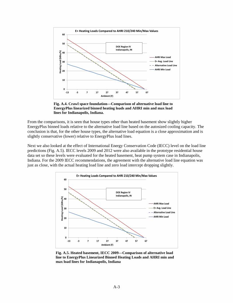
A-3
0
10
20
30
40
50
60
-13 -3 7 17 27 37 47 57 67
Heat
ing
Load
(kBt
u/h)
Ambient (F)
E+ Heating Loads Compared to AHRI 210/240 Min/Max Values
AHRI Max Load
E+ Avg. Load Line
Alternative Load Line
AHRI Min Load
DOE Region IVIndianapolis, IN
Fig. A.4. Crawl space foundation—Comparison of alternative load line to EnergyPlus linearized binned heating loads and AHRI min and max load lines for Indianapolis, Indiana.
From the comparisons, it is seen that house types other than heated basement show slightly higher EnergyPlus binned loads relative to the alternative load line based on the autosized cooling capacity. The conclusion is that, for the other house types, the alternative load equation is a close approximation and is slightly conservative (lower) relative to EnergyPlus load lines.
Next we also looked at the effect of International Energy Conservation Code (IECC) level on the load line predictions (Fig. A.5). IECC levels 2009 and 2012 were also available in the prototype residential house data set so these levels were evaluated for the heated basement, heat pump system case in Indianapolis, Indiana. For the 2009 IECC recommendations, the agreement with the alternative load line equation was just as close, with the actual heating load line and zero load intercept dropping slightly.
0
10
20
30
40
50
60
-13 -3 7 17 27 37 47 57 67
Hea
ting
Loa
d (k
Btu/
h)
Ambient (F)
E+ Heating Loads Compared to AHRI 210/240 Min/Max Values
AHRI Max Load
E+ Avg. Load Line
Alternative Load Line
AHRI Min Load
DOE Region IVIndianapolis, IN
Fig. A.5. Heated basement, IECC 2009—Comparison of alternative load line to EnergyPlus Linearized Binned Heating Loads and AHRI min and max load lines for Indianapolis, Indiana

A-4
For the 2012 IECC recommendations, the EnergyPlus load line is lower than the alternative load line, with a flatter 1.02 slope and slightly lower 54ºF zero load balance point (Fig. A.6). This design represents a high-performance house with quite low infiltration and so is a significant departure from the average housing stock in the United States.
0
10
20
30
40
50
60
-13 -3 7 17 27 37 47 57 67
Hea
ting
Loa
d (k
Btu/
h)
Ambient (F)
E+ Heating Loads Compared to AHRI 210/240 Min/Max Values
AHRI Max Load
E+ Avg. Load Line
Alternative Load Line
AHRI Min Load
DOE Region IVIndianapolis, IN
Fig. A.6. Heated basement, IECC 2012 -- Comparison of alternative load line to EnergyPlus linearized binned heating loads and AHRI min and max load lines for Indianapolis, Indiana.
Next we investigated the calculated heating loads in DOE prototype houses with the most prevalent foundation types in Regions I, II, and VI. This was a slab foundation in Regions I and II and a crawl space foundation in the marine climate of Region VI. The locations selected for these three regions, respectively, were Tampa, Florida, Fort Worth, Texas, and Portland, Oregon. The load line comparisons for these three cases are shown in Fig. A.7 – A.9. The agreement between the EnergyPlus load lines and the alternative load lines are generally quite good and much closer than with the AHRI minimum load line, with the possible exception of ambients above 55°F. The zero load ambients for these three locations are ~62°F, 59°F, and 60°F. The higher zero load ambients for these milder locations are most likely due to a combination of lower insulation levels and/or higher infiltration levels.

A-5
0
10
20
30
40
50
60
70
-13 -3 7 17 27 37 47 57 67
Hea
ting
Loa
d (k
Btu
/h)
Ambient (F)
E+ Heating Loads Compared to AHRI 210/240 Min/Max Values
AHRI Max Load
E+ Avg. Load Line
Alternative Load Line
AHRI Min Load
DOE Region ITampa, Florida
Fig. A.7. Slab foundation, IECC 2006 -- Comparison of alternative load line to EnergyPlus linearized binned heating loads and AHRI min and max load lines for Tampa, Florida
0
10
20
30
40
50
60
70
-13 -3 7 17 27 37 47 57 67
Hea
tin
g Lo
ad (
kBtu
/h)
Ambient (F)
E+ Heating Loads Compared to AHRI 210/240 Min/Max Values
AHRI Max Load
E+ Avg. Load Line
Alternative Load Line
AHRI Min Load
DOE Region IIFort Worth, Texas
Fig. A.8. Slab foundation, IECC 2006 -- Comparison of alternative load line to EnergyPlus linearized binned heating loads and AHRI min and max load lines for Fort Worth, Texas

A-6
0
10
20
30
40
50
60
-13 -3 7 17 27 37 47 57 67
Hea
tin
g Lo
ad (k
Btu
/h)
Ambient (F)
E+ Heating Loads Compared to AHRI 210/240 Min/Max Values
AHRI Max Load
E+ Avg. Load Line
Alternative Load Line
AHRI Min Load
DOE Region VIPortland, OR
Fig. A.9. Crawl space foundation, IECC 2006 -- Comparison of alternative load line to EnergyPlus linearized binned heating loads and AHRI min and max load lines for Portland, Oregon
In Table A.1, all the considered house locations, types, and IECC year are listed along with the EnergyPlus autosized nominal cooling capacity levels.

A-7
Table A.1. Summary of locations and house types modeled in EnergyPlusa and cooling capacity sizes autoselectedb
Location House type IECC year
Net cooling capacity (tons)
DOE Region IV Indianapolis, Indiana Heated basement 2006 2.3 Indianapolis, Indiana Unheated basement 2006 2.2 Indianapolis, Indiana Slab 2006 2.1 Indianapolis, Indiana Crawl space 2006 2.3 Indianapolis, Indiana Heated basement 2009 2.2 Indianapolis, Indiana Heated basement 2012 1.9 Philadelphia, Pennsylvania Heated basement 2006 2.5 Omaha, Nebraska Heated basement 2006 2.5 Peoria, Illinois Heated basement 2006 2.4
DOE Region III Atlanta, Georgia Heated basement 2006 2.5 Oklahoma City, Oklahoma Heated basement 2006 2.8
DOE Region V Minneapolis, Minnesota Heated basement 2006 2.4 Eagle County, Colorado Heated basement 2006 2.0
DOE Region I Tampa, Florida Slab 2006 2.7
DOE Region II Fort Worth, Texas Slab 2006 2.9
DOE Region VI Portland, Oregon Crawl space 2006 1.9 a EnergyPlus V8.1 results b Set points: cooling = 75°F; heating = 70°F


B-1
APPENDIX B. HEATING LOAD HOURS, SEASONAL HEATING LOADS, AND REGIONAL HSPF EFFECTS FOR ALTERNATIVE
LOAD LINES COMPARED TO AHRI 210/240
Equations for the alternative heating load line [used for heating seasonal performance factor (HSPF) calculations] and the related seasonal heating load calculation (used to determine heating operating costs) are given in their most general form below. (For the alternative load line with a fixed zero heating load ambient, then T_zl = 55 and the vz subscript is replaced by 55.)
Heating Load (Tj) = Qc(95) * 1.3 * (T_zl – Tj)/(T_zl – 5)
and
Qh_seasonal_alt = HLH_vz * DHR_vz
where
T_zl is the zero load temperature,
Tj is the bin temperature,
T_d is the design day temperature,
HLH_vz = 24 * D-D_vz/(T_zl – T_d),
where D-D_vz= Total Heating Hours / 24. * ∑ fractional bin-hours * (T_zl -Tj), and
DHR_vz = (T_zl - T_d)/(T_zl – 5) * 1.3 * Qc(95).
Total heating hours were derived for each region from the original HLH_65 values (used to obtain D-D_65 values) and the fractional bin-hours in Table 17 of Appendix C of AHRI 210/240.
Next, the alternative seasonal heating load can be rewritten as
Qh_seasonal_alt = 24 * D-D_vz* 1.3* Qc(95)/(T_zl – 5).
The seasonal heating load change from the alternative approach developed in this study relative to the current 210/240 method can be written as
Seasonal Load Change Factor = [D-D_vz* 1.3 / (T_zl – 5)] / [D-D_65* 0.77 / 60 ]
which simplifies to
Seasonal Load Change Factor = 101.3 * D-D_vz / (T_zl – 5)] / D-D_65
where the actual seasonal load change ratio is the above change factor times the rated Qc(95) / Qh(47) values for each particular unit.

B-2
Table B.1 lists for each DOE region the values of design day temperature T_d, and heating load hours for the current 65°F zero load base temperature used in AHRI 210/240. This is followed in the table by heating load hours to a 55°F zero load base and those to a variable zero load base temperature given by T_zl.
Table B.1. Regional heating load hours for current and alternative load line approaches
Approach input
DOE region I II III IV V VI
T_d (°F) 37 27 17 5 –10 30 HLH_65 750 1250 1750 2250 2750 2750 HLH_55 407 784 1198 1701 2202 1648 HLH_vz 562 909 1363 1701 2202 1974 T_zl (°F) 60 58 57 55 55 58
Table B.2 shows the degree-days for the current zero load base 65°F, alternative base 55°F, and variable base temperature T_zl. For the two alternative load line representations, the seasonal load change factors are given as defined earlier in the appendix. It can be seen from these results that the variable zero load base approach gives seasonal load changes for all DOE regions that are more consistent with the higher alternative load lines predicted by the EnergyPlus simulations in all regions. Most importantly, these results are close matches to the higher seasonal loads obtained from the EnergyPlus analyses for the DOE prototype houses.
Table B.2. Regional degree days and seasonal load change factors for current and alternative load line approaches
Approach input
DOE region I II III IV V VI
DD_65 875 1979 3500 5625 8594 4010 DD_55 305 915 1896 3543 5964 1717 SLCF* 0.707 0.936 1.098 1.276 1.757 0.867 T_zl (°F) 60 58 57 55 55 58 DD_vz 539 1174 2158 3543 5964 2303 SLCF* 1.134 1.134 1.264 1.276 1.757 1.098
*SLCF: seasonal load change factor. The actual load change relative to current 210/240 heating loads is the load change factor times Qc(95)/Qh(47) for a particular unit.
The reason for the significant difference in the calculated seasonal loads between the fixed 55°F and variable zero load options in Table B.2 for regions I, II, III, and VI is that the zero load shift to intermediate ambients between 55°F and 65°F, as appropriate, adds load over most of the heating hours

B-3
for these regions. This can be seen by comparing normalized load-hour results for 210/240 against those with the alternative load lines with a 55F base and a variable base zero load ambient, as shown in Figs. B.1 to B.3. (Normalized load-hours are the product of HLH’s * bin loads * fractional bin hours/nominal capacity, with the fractional bin hours given by Table 17 in Appendix C of AHRI 210/240.) For Regions I–III and especially Region VI, this shift to variable zero load ambients between 55°F and 65°F results in a moderate to significant increase in calculated heating load.
0.0
0.2
0.4
0.6
0.8
1.0
1.2
1.4
1.6
-23 -13 -3 7 17 27 37 47 57 67
Nor
mal
ized
Heat
ing
Load
-Hou
rs/1
00
Ambient Temperature (°F)
AHRI 210/240 Min DHR Load-Hour Distributions
Region VI Load-Hours/100
Region V Load-Hours/100
Region IV Load-Hours/100
Region III Load-Hours/100
Region II Load-Hours/100
Region I Load-Hours/100
Fig. B.1. Normalized load-hour distributions for AHRI 210/2040 minimum load line approach with 65°f zero load ambient.
0.0
0.2
0.4
0.6
0.8
1.0
1.2
1.4
1.6
-23 -13 -3 7 17 27 37 47 57 67
Nor
mal
ized
Heat
ing
Load
-Hou
rs/1
00
Ambient Temperature (°F)
Load-Hour Distributions, Alt. Load Line with 55°F Zero Load Base
Region VI Load-Hours/100
Region V Load-Hours/100
Region IV Load-Hours/100
Region III Load-Hours/100
Region II Load-Hours/100
Region I Load-Hours/100
Fig. B.2. Normalized load-hour distributions for alternative load line approach with 55°f zero load ambient.
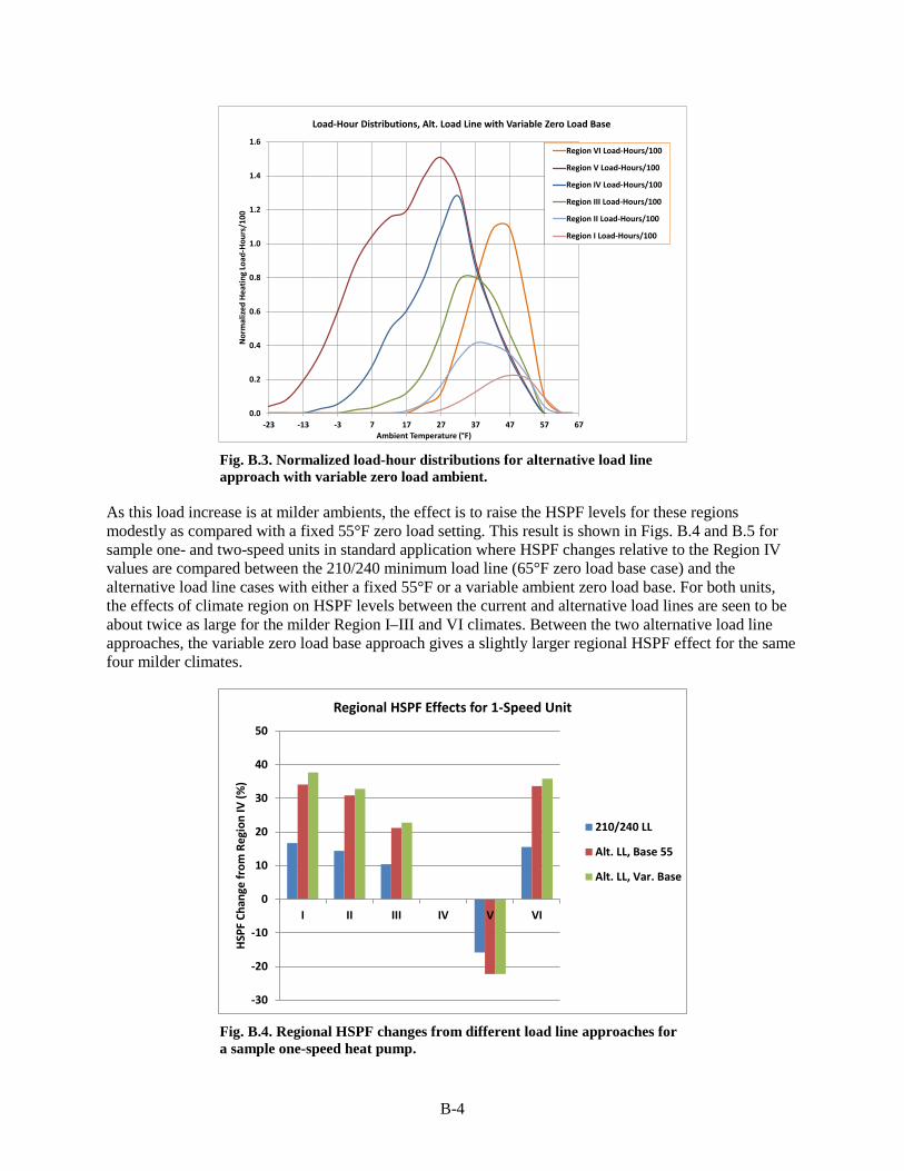
B-4
0.0
0.2
0.4
0.6
0.8
1.0
1.2
1.4
1.6
-23 -13 -3 7 17 27 37 47 57 67
Nor
mal
ized
Hea
ting
Load
-Hou
rs/1
00
Ambient Temperature (°F)
Load-Hour Distributions, Alt. Load Line with Variable Zero Load Base
Region VI Load-Hours/100
Region V Load-Hours/100
Region IV Load-Hours/100
Region III Load-Hours/100
Region II Load-Hours/100
Region I Load-Hours/100
Fig. B.3. Normalized load-hour distributions for alternative load line approach with variable zero load ambient.
As this load increase is at milder ambients, the effect is to raise the HSPF levels for these regions modestly as compared with a fixed 55°F zero load setting. This result is shown in Figs. B.4 and B.5 for sample one- and two-speed units in standard application where HSPF changes relative to the Region IV values are compared between the 210/240 minimum load line (65°F zero load base case) and the alternative load line cases with either a fixed 55°F or a variable ambient zero load base. For both units, the effects of climate region on HSPF levels between the current and alternative load lines are seen to be about twice as large for the milder Region I–III and VI climates. Between the two alternative load line approaches, the variable zero load base approach gives a slightly larger regional HSPF effect for the same four milder climates.
-30
-20
-10
0
10
20
30
40
50
I II III IV V VI
HSPF
Cha
nge
from
Reg
ion
IV (%
)
Regional HSPF Effects for 1-Speed Unit
210/240 LL
Alt. LL, Base 55
Alt. LL, Var. Base
Fig. B.4. Regional HSPF changes from different load line approaches for a sample one-speed heat pump.

B-5
-30
-20
-10
0
10
20
30
40
50
I II III IV V VI
HSPF
Cha
nge
from
Reg
ion
IV (%
)
Regional HSPF Effects for 2-Speed Unit
210/240 LL
Alt. LL, Base 55
Alt. LL, Var. Base
Fig. B.5. Regional HSPF changes from different load line approaches for a sample two-speed heat pump.
Between the one- and two-speed cases shown in Figs. B.4 and B.5 for the variable zero load ambient, alternative load line, the differences in HSPF change by region are small. In Fig. B.6, the average regional HSPF adjustments for these cases are shown relative to the HSPFs in Region IV. Relative to the current HSPF ratings, these effects would be applied after the average 16% reductions in HSPF for Region IV, as discussed in Sect. 4.2 of the report. These average HSPF changes can be used with the equations and tables given earlier in this appendix for the variable zero load ambient, alternative load line to estimate the seasonal heating energy use for a one- and two-speed heat pump of current HSPF rating in any of the six DOE climate regions.
-30
-20
-10
0
10
20
30
40
50
I II III V VI
HSPF
Cha
nge
from
Reg
ion
IV (%
)
Average Regional HSPF Effects from Region IV, Alternative LL
Avg. HSPFChange
Fig. B.6. Average regional HSPF changes from Region IV levels using the variable zero load ambient, alternative load line for one- and two-speed heat pumps in standard application.

B-6
The reported heating season operating costs in the AHRI directory are actually based on an assumed national average value for HLH_65 of 2080 (CFR 430.23) as compared to the HLH_65 value of 2250 for DOE Region IV. However the DHR_min value in this calculation is based on the Region IV definition. To convert this for use with the alternative load line, a simple ratio of 2080/2250 can be applied to the Region IV HLH value of 1701, giving a modified national average HLH_55 (or HLH_vz) value of 1572 hours. With this, the national average heating season energy use would be calculated from
National average heating season energy use = 1572 * 1.3 * Qc(95)/HSPF_alt_IV
where HSPF_alt_IV is the HSPF in DOE climate region IV with the alternative load line, rather than being based on a standardized minimum design heating requirement (U. S. CFR 430.23) as in
National average heating season energy use = 2080 * 0.77 * DHR_standardized/HSPF_rated
where DHR_standardized = Qh(47) rounded to the nearest 5-, 10-, or 20-thousand Btu/h value per Table 18 in Appendix C of AHRI 210/240 and HSPF_rated is the HSPF value by the current ratings procedure.. Other than the effects of rounding and the Qc(95)/Qh(47) ratio for individual units, the 27.6% increase in calculated heating season energy use for Region IV with the alternative load line applies directly to this calculation when the average national HLH value is scaled as noted above to use 1572 in place of 2080 hours.
While the listed heating season energy use values are based on Region IV loads and HSPF and a national average value for heating load hours, application of the regional heating loads and energy use calculations as described in Appendix C, Sect. 4.3.1 of 210/240 require representative values for HSPF in those regions. For manufacturers and other interested parties with access to 210/240 test data sets, the variable zero load approach described in this appendix can be used to obtain regional HSPF values and seasonal energy use that is much more consistent than the current 210/240 approach with the EnergyPlus results for DOE prototype residential IECC 2006 houses simulated in this report. In lieu of available 210/240 test data sets, approximate regional HSPF values and seasonal energy use can be obtained using first approximation averages for HSPF effects in standard applications as given in Sect. 4.2 of the report, combined with the seasonal load equations, HLH, T_d, T_vz values, and regional HSPF adjustment factors given in this appendix. Approximate regional values for heating season energy use can be obtained from
Regional heating season energy use = HLH_vz * (T_zl - T_d)/(T_zl – 5) * 1.3 * Qc(95) / HSPF_alt_regional
where HSPF_alt_regional is the regional HSPF for the alternative load line given by
HSPF_alt_regional = HSPF_alt_IV * HSPF_avg_regional_fac
where HSPF_alt_IV can be approximated by HSPF_rated *0.84 (based on the average 16% HSPF reduction in DOE Region IV from Sect. 4.2) and the HSPF_avg_regional_fac values as given in Table B.3, as shown earlier in Fig. B.6.

B-7
Table B.3. Inputs for calculating average regional heating season energy use for the variable ambient zero load, alternative load line approach
Calculation inputs DOE region
I II III IV V VI HLH_vz 562 909 1363 1701 2202 1974 T_zl (°F) 60 58 57 55 55 58 T_d (°F) 37 27 17 5 –10 30 HSPF_avg_regional_fac 1.38 1.32 1.22 1.00 0.79 1.36
For completeness, we include in Figs. B.7 through B.11 comparison plots of the binned EnergyPlus load lines and alternative load lines with the variable T_zl values noted earlier in this appendix for DOE Regions I, II, III, and VI against the min and max AHRI 210/240 load lines. These plots show the slightly improved load (rate) matching provided with the variable zero load option.
0
10
20
30
40
50
60
70
-13 -3 7 17 27 37 47 57 67
Hea
tin
g Lo
ad (
kBtu
/h)
Ambient (F)
E+ Heating Loads Compared to AHRI 210/240 Min/Max Values
AHRI Max Load
E+ Avg. Load Line
Alternative Load Line
AHRI Min Load
DOE Region ITampa, Florida
Fig. B.7. Comparison of alternative load line with 60°F zero load ambient to EnergyPlus linearized binned heating loads and AHRI min and max load lines for Tampa, Florida – Slab foundation, IECC 2006.

B-8
0
10
20
30
40
50
60
70
-13 -3 7 17 27 37 47 57 67
Hea
ting
Loa
d (k
Btu
/h)
Ambient (F)
E+ Heating Loads Compared to AHRI 210/240 Min/Max Values
AHRI Max Load
E+ Avg. Load Line
Alternative Load Line
AHRI Min Load
DOE Region IIFort Worth, Texas
Fig. B.8. Comparison of alternative load line with 58°F zero load ambient to EnergyPlus linearized binned heating loads and AHRI min and max load lines for Fort Worth, Texas – Slab foundation, IECC 2006.
0
10
20
30
40
50
60
70
-13 -3 7 17 27 37 47 57 67
Hea
ting
Loa
d (k
Btu/
h)
Ambient (F)
E+ Heating Loads Compared to AHRI 210/240 Min/Max Values
AHRI Max Load
E+ Avg. Load Line
Alternative Load Line
AHRI Min Load
DOE Region IIIAtlanta, GA
Fig. B.9. Comparison of alternative load line with 57°F zero load ambient to EnergyPlus linearized binned heating loads and AHRI min and max load lines for Atlanta, Georgia – Slab foundation, IECC 2006.

B-9
0
10
20
30
40
50
60
70
-13 -3 7 17 27 37 47 57 67
Hea
ting
Loa
d (k
Btu/
h)
Ambient (F)
E+ Heating Loads Compared to AHRI 210/240 Min/Max Values
AHRI Max Load
E+ Avg. Load Line
Alternative Load Line
AHRI Min Load
DOE Region IIIOklahoma City, OK
Fig. B.10. Comparison of alternative load line with 57°F zero load ambient to EnergyPlus linearized binned heating loads and AHRI min and max load lines or Oklahoma City, Oklahoma – Slab foundation, IECC 2006.
0
10
20
30
40
50
60
-13 -3 7 17 27 37 47 57 67
Hea
ting
Loa
d (k
Btu/
h)
Ambient (F)
E+ Heating Loads Compared to AHRI 210/240 Min/Max Values
AHRI Max Load
E+ Avg. Load Line
Alternative Load Line
AHRI Min Load
DOE Region VIPortland, OR
Fig. B.11. Comparison of alternative load line with 58°F zero load ambient to EnergyPlus linearized binned heating loads and AHRI min and max load lines for Portland, Oregon -- Crawl space foundation, IECC 2006.