
An Adaptive Cascaded ILA- and DLA-Based Digital ...
12
HAL Id: hal-01895641 https://hal.archives-ouvertes.fr/hal-01895641 Submitted on 5 Dec 2018 HAL is a multi-disciplinary open access archive for the deposit and dissemination of sci- entific research documents, whether they are pub- lished or not. The documents may come from teaching and research institutions in France or abroad, or from public or private research centers. L’archive ouverte pluridisciplinaire HAL, est destinée au dépôt et à la diffusion de documents scientifiques de niveau recherche, publiés ou non, émanant des établissements d’enseignement et de recherche français ou étrangers, des laboratoires publics ou privés. An Adaptive Cascaded ILA- and DLA-Based Digital Predistorter for Linearizing an RF Power Amplifier Han Le Duc, Bruno Feuvrie, Matthieu Pastore, Yanping Wang To cite this version: Han Le Duc, Bruno Feuvrie, Matthieu Pastore, Yanping Wang. An Adaptive Cascaded ILA- and DLA- Based Digital Predistorter for Linearizing an RF Power Amplifier. IEEE Transactions on Circuits and Systems I: Regular Papers, IEEE, 2019, 66 (3), pp.1031-1041. 10.1109/TCSI.2018.2872465. hal-01895641
Transcript of An Adaptive Cascaded ILA- and DLA-Based Digital ...

HAL Id: hal-01895641https://hal.archives-ouvertes.fr/hal-01895641
Submitted on 5 Dec 2018
HAL is a multi-disciplinary open accessarchive for the deposit and dissemination of sci-entific research documents, whether they are pub-lished or not. The documents may come fromteaching and research institutions in France orabroad, or from public or private research centers.
L’archive ouverte pluridisciplinaire HAL, estdestinée au dépôt et à la diffusion de documentsscientifiques de niveau recherche, publiés ou non,émanant des établissements d’enseignement et derecherche français ou étrangers, des laboratoirespublics ou privés.
An Adaptive Cascaded ILA- and DLA-Based DigitalPredistorter for Linearizing an RF Power Amplifier
Han Le Duc, Bruno Feuvrie, Matthieu Pastore, Yanping Wang
To cite this version:Han Le Duc, Bruno Feuvrie, Matthieu Pastore, Yanping Wang. An Adaptive Cascaded ILA- and DLA-Based Digital Predistorter for Linearizing an RF Power Amplifier. IEEE Transactions on Circuitsand Systems I: Regular Papers, IEEE, 2019, 66 (3), pp.1031-1041. �10.1109/TCSI.2018.2872465�.�hal-01895641�

Accep
ted m
anus
critpt
An Adaptive Cascaded ILA- and DLA-BasedDigital Predistorter for Linearizing
an RF Power AmplifierHan Le Duc , Bruno Feuvrie, Matthieu Pastore, and Yide Wang
Abstract— This paper presents a novel adaptive digital pre-distortion (DPD) technique based on a cascade of an adaptiveindirect learning architecture (ILA) and a static direct learningarchitecture (DLA) using a linear interpolation look-up-table(LILUT). The static LILUT-DLA-based DPD is designed toidentify the inverse of a radio-frequency power amplifier (PA)model. The cascaded system of the DLA-based predistorter (PD)and PA is theoretically linear. However, in real-time applications,the PA characteristics change with time due to process, supplyvoltage, and temperature variations, making this cascaded systemnot strictly linear, which results in some residual nonlineardistortion at the PA output. This residual distortion is effectivelycompensated by an additional adaptive ILA-based PD usingleast mean squares or recursive least squares. Thanks to theincorporation of the static DLA, the proposed DPD approach isless sensitive to the PA output noise, ensuring a better preinverseof the PA and also requiring a smaller number of adaptive coef-ficients than either the adaptive stand-alone DLA- or ILA-basedDPDs. The experimental results show that the proposed DPDtechnique effectively linearizes the PA, even if its characteristicschange, and obtains better linearization performance than eitherthe classical stand-alone DLA- or stand-alone ILA-based DPDs.
Index Terms— Nonlinear systems, power amplifier, adaptivedigital predistortion (DPD), indirect learning architecture (ILA),direct learning architecture (DLA), adaptive algorithm.
I. INTRODUCTION
MODERN communication systems are continuouslyevolving to satisfy the requirement of high data rate
for multimedia communications. The signals of these systemshave high peak-to-average power ratio (PAPR) and wide band-width, leading to stringent linearity requirements for signalamplification.
Manuscript received March 27, 2018; revised July 24, 2018 andSeptember 18, 2018; accepted September 21, 2018. This work was supportedby BPI France, region Occitanie and region Nouvelle Aquitaine, through theAPOGEES project. This paper was recommended by Associate Editor J. Lota.(Corresponding author: Han Le Duc.)
H. Le Duc is with the Institute of Electronics and Telecommunicationsof Rennes, UMR CNRS 6164, University of Nantes, 44035 Nantes,France, and also with Telerad Company, 64603 Anglet, France (e-mail:[email protected]).
B. Feuvrie and Y. Wang are with the Institute of Electronics andTelecommunications of Rennes, UMR CNRS 6164, University of Nantes,44035 Nantes, France.
M. Pastore is with Telerad Company, 64603 Anglet, France.
Fig. 1. DPD concept. (a) Block diagram. (b) Transfer functions of DPD unit,PA, and DPD+PA system.
Two key quality factors of radio frequency (RF) poweramplifiers (PAs) in modern wireless communication systemsare efficiency and linearity. Unfortunately, it is hard to simulta-neously obtain the above two requirements due to the inherentcharacteristics of PAs. In order to maximize the efficiency,PAs should operate close to saturation, producing strongnonlinear distortion in the amplified signal. This distortionincreases the error vector magnitude (EVM) and also resultsin spectral regrowth, causing interference to neighboring chan-nels and increasing the adjacent channel power ratio (ACPR).By operating the PA far below saturation, its nonlinear behav-ior can be reduced. However, this leads to low power efficiencybecause of the high PAPR of modern communication signals.As a result, the PA design has to make a tradeoff betweenefficiency and linearity. In order to fulfill the efficiency require-ment without sacrificing linearity, PA linearization techniquesare required [1]. Thanks to its highly cost-effective andeasy implementation, baseband digital predistortion (DPD)is a popular and widely used linearizion technique [2]–[11].Its principle is shown in Fig. 1. The DPD concept places apredistorter (PD) block in front of the PA. Ideally, the nonlin-ear transfer function of the PD is the inverse of that of the PA.Consequently, the cascaded PD and PA system becomes linearand the original input is amplified by a constant gain. ThePD is added in the baseband, working entirely in the digitaldomain. The performance of the DPD is controlled by a set ofcomplex coefficients ωkm that can be estimated either offline,based on a block of measured input and output samples of

Accep
ted m
anus
critptFig. 2. Block diagram of conventional ILA-based DPD.
the PA, or online in an adaptive way based on real-time mea-surements of the PA input and output signals [9], [12]. Sincethe characteristics of the PA are usually unknown, learningarchitectures and adaptive algorithms are employed to estimateits inverse function. There are two commonly used learningarchitectures for identifying the parameters of a PD: indi-rect learning architecture (ILA) [12]–[17] and direct learningarchitecture (DLA) [8]–[11], [18]–[20]. The ILA-based DPDcomputes an inverse model of the PA via the post-distorter(or training) block, whose input is the output of the PA asillustrated in Fig. 2, where G0 is the gain of the linearized PA.The PD transfer function is an exact duplicate of that of thetraining block. At convergence, the identified coefficients ofthe post-distorter are copied to the PD, making the cascadedPD and PA system behave linearly. The ILA-based DPD archi-tecture can be performed either in an offline manner using leastsquares (LS) [3] or in an adaptive manner using an adaptivealgorithm such as least mean squares (LMS) or recursiveleast squares (RLS) [4], [21]. The key advantage of the ILA-based DPD is its implementation simplicity [15]. However,it suffers from two typical drawbacks [12], [16], [17]. Firstly,the adaptive algorithm may converge to a biased solution dueto the presence of noise in the measured PA output. Secondly,the efficiency of the ILA-based PD performance is poor whenthe PA works near its saturation region [4], [17]. To cope withthe ILA-based PD noise-induced bias problem, the output ofa forward model of the PA can be used instead of using thereal noisy PA output to identify the inverse model [14], [16].Although these approaches yield better linearity performancethan the original ILA-based PD, their performance depends onthe accuracy of the PA forward model [4].
The above mentioned drawbacks are not present inDLA-based DPD techniques, which can be performed eitheronline [9]–[11], as shown in Fig. 3(a), or offline [8], [22], asillustrated in Fig. 3(b). In the adaptive case, the PD parame-ters are identified by comparing the wanted signal G0 u(n)with the PA output y(n). The error produced at the PAoutput is minimized by using an adaptive algorithm such asLMS or RLS [10], [12], [14], [17], [21]. For these approaches,the computation of an instantaneous estimate of the gradientof mean square error with respect to the PD coefficientsis complex and computationally expensive. Thus, most of
Fig. 3. Block diagram of DLA-based DPD. (a) Online. (b) Offline.
these are complex in structure, and also suffer from slowconvergence [4]. In the offline case, the coefficients of the PAmodel are extracted using the LS method after gathering a setof input and output samples of the PA. The PD identificationtechniques proposed in [8], [22], and [23] use a look-up-table (LUT) to significantly reduce the computational timerequired in a conventional memory-polynomial-based DPD.However, the crucial drawback of these DLA-based DPDtechniques is to require a sufficiently large LUT in order toobtain good linearization performance. To cope with this draw-back, the DLA-based linearization technique in [8] proposesa linearly interpolated LUT (LILUT) algorithm, increasingthe indexing efficiency of the LUT, and hence reducingthe LUT size. This is actually an improved solution of theLUT-DLA-based DPD proposed in [22]. Although the LILUT-DLA-based DPD proposed in [8] shows good performancewith low complexity and fast convergence, it is limited toapplications where the PAs are operating under relativelystable conditions, e.g., the PA characteristics remain almostconstant over time. However, in practice, the PA characteristicsmay change rapidly with time due to process, supply voltage,and temperature (PVT) variations. If the static DPD in [8] isemployed, the different DPD functions or coefficients must bereadapted to changes in the PA characteristics, which is moredifficult than an ILA-based DPD.
Considering the aforementioned pros and cons of conven-tional learning architectures (DLA and ILA) and the offlineLILUT-DLA-based DPD proposed in [8], we propose inthis paper, a novel adaptive DPD architecture cascading theadaptive ILA-based PD and offline (or static) LILUT-DLA-based PD. The static LILUT-DLA-based PD is designed tolinearize the PA for a specific condition such that the cascadedsystem of the DLA-based PD and PA, named as CDPAin the rest of the paper, is theoretically linear. As the PAcharacteristics change with time due to PVT variations, theCDPA is no longer linear, causing some residual nonlinear

Accep
ted m
anus
critpt
distortion at the PA output. Since the most significant partof the PA nonlinear memory effects is compensated by thestatic DLA-based PD, this residual distortion can be effectivelymitigated by the proposed adaptive ILA-based PD placed infront of the CDPA. Thanks to the incorporation of the staticDLA-based PD with the PA, the CDPA is much less nonlinearthan the PA and the proposed additional adaptive ILA-basedPD will be less complex and easier to design than either theadaptive stand-alone DLA- or ILA-based PDs. As a result,the proposed DPD solves several problems that arise whenusing either the stand-alone DLA- or ILA-based DPDs tolinearize a PA whose characteristics change due to PVT drifts.
The rest of the paper is organized as follows. Section IIreviews the offline (or static) stand-alone LILUT-DLA-basedDPD. Section III describes the proposed adaptive linearizationtechnique. Experimental validation results are presented inSection IV. Conclusions are drawn in Section V.
II. REVIEW OF THE OFFLINE STAND-ALONE
LILUT-DLA-BASED DPD
This section reviews the offline (or static) stand-aloneDLA-based DPD using the LILUT proposed in [8]. A simpleblock diagram is shown in Fig. 3(b). Due to its simpleimplementation, the MP-based model is widely applied forbehavioral modeling and predistortion of PAs and transmittersexhibiting nonlinear memory effects [1], [2].
Let ckm denote the coefficients of the MP-based model ofa PA. These coefficients can be identified by the LS techniqueusing the input and output data measured from the PA asin [24]. The input and output of the PA model can be expressedas [3]
y(n) =N∑
k=1
M∑
m=0
ckm x(n − m)|x(n − m)|k−1, (1)
where N and M are, respectively, the nonlinear order andmemory depth of the MP-based model of the PA, and y(n)and x(n) denote, respectively, the output and input samples ofthe PA. Ideally, the output of the CDPA system is
y(n) = G0u(n), (2)
where u(n) denotes the input of the CDPA system. Theoutput y(n) can be decomposed into two parts: the staticpart s(n) depending only on the current input sample (m = 0)and the dynamic part d(n) formed by only the previous inputsamples (m = 1, · · · , M ) as
y(n) = s(n) + d(n) = G0u(n), (3)
where
s(n) =N∑
k=1
ck0x(n)|x(n)|k−1, (4)
and
d(n) =N∑
k=1
M∑
m=1
ckm x(n − m)|x(n − m)|k−1, (5)
TABLE I
INPUT AND OUTPUT OF LILUT
where |x(n)| denotes the amplitude of the predistorted sig-nal x(n). Given linear gain G0 and the baseband inputu(n), the goal of identification is to determine the predistortedsignal x(n) at the PD output such that the CDPA systembehaves linearly. To solve this optimization problem, (4) isrewritten as
s(n) = e jαN∑
k=1
ck0|x(n)|k = G0u(n) − d(n), (6)
where α is the phase of the predistorted signal x(n). Therightmost side of (6) can be computed at time instant n.Taking absolute value of both sides of (6), the amplitude ofthe predistorted signal is then the real positive root (whichalways exists [25]) of the following polynomial:
∣∣∣∣∣
N∑
k=1
ck0|x(n)|k∣∣∣∣∣ − |G0u(n) − d(n)| = 0. (7)
The roots of the polynomial of the left-hand side of (7) canbe determined by a classical root-finding process [25].
Although the root-finding process shows good lineariza-tion performance, it is very time-consuming. Thus, it is notapplicable in a real-time application. Therefore, in [8], theroot-finding process is substituted by a LILUT algorithm,which estimates the amplitude |x(n)| and phase α of x(n)based on (6). Firstly, the dynamic range of |x(n)| is estimatedaccording to the characteristics of the PA [26]. Secondly,the determined dynamic range of |x(n)| is divided into K inter-vals with equal length |�x |. The LILUT is then constructedand shown in Table I, where its input E(k) is computed as
E(k) =∣∣∣∣∣
N∑
i=1
ci0|k�x |i∣∣∣∣∣ , (8)
and its two outputs, corresponding to the amplitude R(k) andamplitude slope SR(k), are calculated as
R(k) = k�x, (9)
SR(k) = R(k + 1) − R(k)
E(k + 1) − E(k), 0 ≤ k ≤ K − 1. (10)
Finally, the amplitude and phase of the predistorted signalx(n) are determined by Algorithm 1, where L is the numberof training samples.

Accep
ted m
anus
critptFig. 4. Proposed adaptive DPD using a combined learning architecture.
Algorithm 1 Offline Stand-Alone LILUT-DLA-Based DPD1: Initialize: n = 0, d(0) = 02: for n = 1 to L − 1 do3: Compute the static part:
s(n) = G0u(n) − d(n)
4: Find the index m of LUT such that twoadjacent values E(m) and E(m + 1)in Table I, are the closest to |s(n)|
5: Compute the corresponding amplitude|x(n)| by
|x(n)| = R(m) + [|s(n)| − E(m)] SR(m)
6: Calculate the corresponding phase by
α = arg
⎧⎪⎪⎪⎨
⎪⎪⎪⎩
s(n)
N∑k=1
ck0|x(n)|k
⎫⎪⎪⎪⎬
⎪⎪⎪⎭
7: Calculate the predistorted signal
x(n) = |x(n)| e jα
8: end for
III. PROPOSED ONLINE DPD ARCHITECTURE
The offline LILUT-DLA-based DPD presented in Section IIis limited to applications where the PA characteristics do notchange with time. However, this scenario is not the casein practice, especially in reconfigurable systems where thesignal type, modulation, power, etc., can change completely.Furthermore, the adaptive stand-alone ILA-based DPD has anoise problem.
When the PA works close to its saturation region, the cor-relation matrix used to determine the inverse model of thePA is badly conditioned. As a result, the identified modelparameters are very sensitive to noise at the PA output. Thus,we propose a novel adaptive DPD technique shown in Fig. 4,where a combined DLA and ILA architecture is designed.The proposed architecture consists of an adaptive ILA-basedPD followed by a static LILUT-DLA-based PD. The staticLILUT-DLA-based PD uses the LILUT algorithm presented inAlgorithm 1, where a static LILUT in Table I is first computed
for the PA working under a specific condition (temperature).The static CDPA system shown in Fig. 4 is theoretically linearif the PA characteristics do not change. However, if the PAcharacteristics change, the CDPA is no longer linear, resultingin some residual nonlinear distortion at the PA output. Theproposed additional ILA-based PD using LMS or RLS caneffectively mitigate this residual nonlinear distortion. Thanksto the incorporation of the static DLA-based PD with thePA, the correlation matrix of the CDPA output samples isbetter conditioned than that of the uncompensated PA outputsamples. Thus, the proposed DPD is more robust to noise atthe PA output than the stand-alone ILA-based DPD, and canefficiently track coefficient fluctuations of the PA due to PVTdrift.
A. Cascaded Architecture of the LMS-ILA-Based PD andStatic LILUT-DLA-Based PD
The standard ILA-based DPD proposed in [3], [12], [13],[21], and [27] is applied in our solution, shown in Fig. 4. Thepostinverse of the CDPA is identified using a post-distorter (ortraining) block, where z(n) and zp(n) are the input and outputof the post-distorter, respectively. The PD transfer function isan exact duplicate of that of the training block. The ILA-basedPD has input u(n) and output xILA(n).
We assume that both the ILA-based PD and post-distorterare modeled by a MP. The MP-based model of the ILA-basedPD is expressed as [3], [23]
xILA(n) =Q∑
k=1
P∑
m=0
ωkm u(n − m)|u(n − m)|k−1, (11)
where Q and P are the nonlinear order and memory depth ofthe MP-based model, respectively, and ωkm are the coefficientsof the model. The input and output of the post-distorter areexpressed as
zp(n) =Q∑
k=1
P∑
m=0
ωkm z(n − m)|z(n − m)|k−1, (12)
with
z(n) = y(n)
G0. (13)
Let us define a new sequence as
zkm(n) = z(n − m)|z(n − m)|k−1, (14)
In matrix form, the output of the post-distorter (12), can beexpressed as
zp(n) = zT(n)ω, (15)
where symbol T indicates matrix transpose and
z(n) = [z10(n), . . . , zQ0(n), . . . , z1P(n), . . . , zQ P
]T. (16)
The coefficient vector ω is denoted by
ω = [ω10, . . . , ωQ0, . . . , ω1P , . . . , ωQ P
]T. (17)
The error signal is defined by
e(n) = xILA(n) − zp(n) = xILA(n) − zT(n)ω. (18)
Accep
ted m
anus
critpt
The LMS algorithm minimizes the mean square errorE
{|e(n)|2} to identify the coefficients ωkm . The updatingequation is expressed as [28], [29]
ω̂(n) = ω̂(n − 1) − 1
2μ
∂|e(n)|2∂ω̂(n)
= ω̂(n − 1) + μe(n)z(n), (19)
where μ is the step-size parameter of the LMS technique.Finally, the proposed adaptive DPD technique is describedin Algorithm 2 where FPA {· · · } is the PA transfer function,modeled by a MP function.
Algorithm 2 Proposed Adaptive DPD by Cascading theLMS-ILA-Based PD and Static LILUT-DLA-Based PD1: Initialize: n = 0, ω̂(0), μ.2: for n = 1 to L − 1 do3: compute xILA(n) expressed in (11).4: Execute Algorithm 1 ⇒ xDLA(n)5: y(n) = FPA {xDLA(n)} .6: z(n) = y(n)
G0
7: zp(n) = zT(n)ω̂(n − 1).8: Compute the error signal:
e(n) = xILA(n) − zp(n).
9: Update the coefficients:
ω̂(n) = ω̂(n − 1) + μe(n)z(n).
10: End For
The key advantage of the LMS algorithm is its low compu-tational complexity. The price paid for this simplicity is slowconvergence since LMS uses only the step-size to govern itsconvergence speed and steady-state misadjustment. Thus, it ishard to make an optimal trade-off between them [29].
B. Cascaded Architecture of the RLS-ILA-Based PD andStatic LILUT-DLA-Based PD
In order to obtain faster convergence, the RLS algorithm[28], [29] is applied in our framework, to minimize thefollowing weighted sum of magnitude-squared errors:
ζ =n∑
l=0
λn−l |e(l)|2, (20)
where 0 < λ < 1 is the “forgetting factor”. An adaptivecascaded architecture of ILA and DLA using RLS is shownin Algorithm 3, where δ is a positive scalar determined byexperimentation in order to balance the stability with theconvergence rate. Typically, δ > 100σ 2
x , where σ 2x is the
variance of the input. The value of λ is commonly chosenin the range 0.95 < λ < 1 [28], [29].
To simplify the notation, the proposed adaptive DPD archi-tecture of the cascaded ILA- and DLA-based PDs usingLMS is denoted as Design+LMS, and likewise using RLSas Design+RLS.
Algorithm 3 Proposed Adaptive DPD by Cascading theRLS-ILA-Based PD and Static LILUT-DLA-Based PD1: Initialize: n = 0, ω̂(0), P0 = δI2: for n = 1 to L − 1 do3: compute xILA(n) expressed in (11).4: Execute Algorithm 1 ⇒ xDLA(n)5: y(n) = FPA {xDLA(n)} .6: z(n) = y(n)
G0
7: zp(n) = zT(n)ω̂(n − 1).8: Compute the error signal:
e(n) = xILA(n) − zp(n).
9: Compute the Kalman gain vector:
k(n) = P(n − 1)z(n)
λ + zT(n)P(n − 1)z(n)
10: Update the inverse of the correlationmatrix:
P(n) = 1
λ
[P(n − 1) − k(n)zT(n)P(n − 1)
]
11: 5. Update the coefficients of thepost-distorter:
ω̂(n) = ω̂(n − 1) + k(n)e(n)
12: End For
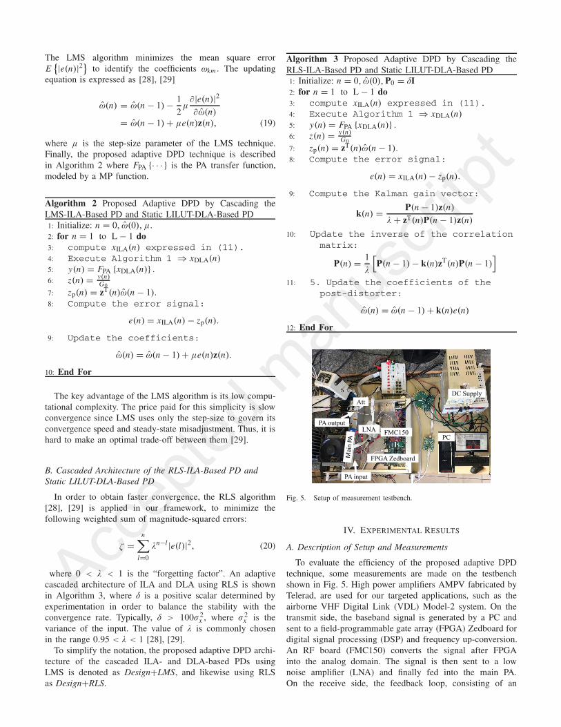
Fig. 5. Setup of measurement testbench.
IV. EXPERIMENTAL RESULTS
A. Description of Setup and Measurements
To evaluate the efficiency of the proposed adaptive DPDtechnique, some measurements are made on the testbenchshown in Fig. 5. High power amplifiers AMPV fabricated byTelerad, are used for our targeted applications, such as theairborne VHF Digital Link (VDL) Model-2 system. On thetransmit side, the baseband signal is generated by a PC andsent to a field-programmable gate array (FPGA) Zedboard fordigital signal processing (DSP) and frequency up-conversion.An RF board (FMC150) converts the signal after FPGAinto the analog domain. The signal is then sent to a lownoise amplifier (LNA) and finally fed into the main PA.On the receive side, the feedback loop, consisting of an

Accep
ted m
anus
critptFig. 6. Measured AM/AM characteristics of the PA at various temperatures.
Fig. 7. Measured gain of the PA at various temperatures.
attenuator (Att), the FMC150, and FPGA Zedboard, is usedto capture the PA output signal, down-convert it to basebandsignal, which is then sent to a PC from FPGA Zedboard formodel extraction and DPD design.
The measured input signal is a quadrature phase shiftkeying (QPSK) modulated signal with 16.8 kHz bandwidthat carrier frequency of 118 MHz. The measured outputpower is 75 W. Let us denote ACPRU1 and ACPRU2 as theACPR values measured at the first and second upper adja-cent channels, corresponding to frequency offsets of 25 kHzand 50 kHz, respectively. Our targeted applications imposestrong constraints on ACPRs (ACPRU1 < −65 dB andACPRU1 < −75 dB) and EVM < 6%. Accurate time-delay alignment between the input and output samples isexecuted using the cross-correlation technique [30]. After atime-alignment process, the obtained data are used to computethe instantaneous complex gain of the PA. The measuredAM/AM characteristics and gain of the PA are shown inFigs. 6 and 7, respectively, for various temperatures. Fromthese figures, one can observe that the AM/AM characteristicsand gain curve are altered as the measured temperatureis varied. The gain of the PA decreases as the temperatureincreases. Thus, a new model of the PA should be re-extractedand used for the corresponding PD identification for eachdifferent temperature. This process makes the DPD systemtoo cumbersome and complex. In order to linearize the PA
Fig. 8. NMSE performance vs. nonlinear order (N ) and memory depth (M)measured at 50oC. (a) NMSE vs. M. (b) NMSE vs. N .
more efficiently, the adaptive DPD is instead required to trackthe coefficient fluctuation of the PA.
B. MP-Based Model Optimization
Due to its low computational cost, satisfactory accuracy, andeasy hardware implementation [1], [2], [14], [24], MP-basedmodels have been widely applied for behavioral modelingand predistortion of PAs exhibiting nonlinear memory effects.Since the PA output in a real measurement is limited tothe frequency band of interest, most published DPD tech-niques [2]–[4], [8], [14], [21] consider only odd-order terms ofthe polynomial. However, it is worth noting that all the terms inthe polynomial, including both odd- and even-order terms forthe models, should be used to achieve the best representationof the PA magnitude and phase responses [31]. Moreover,if taking only odd-order terms for the models, the requirednonlinear order may be higher in order to better model thenonlinear behavior of the PA.
In this framework, we thus use the MP-based modelincluding both odd- and even-order terms. After capturing aparticular set of input and output samples measured at differenttemperatures, each MP-based model of the PA is determinedusing the LS method [3]. In order to reduce the computationalcomplexity, the orders (N and M) of the MP-based modelsare determined using a performance-based sweeping method.Obviously, the nonlinear order and memory depth parametersaffect the normalized mean square error (NMSE) and ACPRperformance [32]. We additionally define ACPR deviation,based on which, the optimal orders of the models are deter-mined. The ACPR deviation σ is the normalized differencebetween ACPRs of the MP-based model output and PA output,expressed as
σ(%) =∣∣∣∣ACPRmodel − ACPRDUT
ACPRDUT
∣∣∣∣ × 100 (21)
where ACPRmodel and ACPRDUT are the ACPRs of themodel output and the device under test (DUT) PA output,respectively. Designations σU1 and σU2 will be used to denotethe measured σ in the first and second upper adjacent channels,respectively. The NMSE and ACPR deviation of each modelare evaluated as a function of the nonlinear order and memorydepth over a wide range of nonlinear orders from 1 to 7and memory depths from 0 to 6. The results reported inFigs. 8 and 9 show that the optimal values of M and N ,

Accep
ted m
anus
critptFig. 9. ACPR deviation σ vs. nonlinear order and memory depth with PA
at 50oC. (a) σU1. (b) σU2.
TABLE II
PERFORMANCE OF THE OPTIMAL MP-BASED
MODELS AT DIFFERENT TEMPERATURES
Fig. 10. Power spectral density (PSD) at 50oC: a) PA input, b) PA output,c) MP-based model output.
to achieve the best NMSE and ACPR deviation, are 1 and 5,respectively. Analogously, the above mentioned performance-based sweeping method is applied to determine optimal mod-els for different temperatures. As can be seen from Table II(bottom three rows), the optimal values of the nonlinear orderand memory depth remain constant for all models when thetemperature changes. The MP-based models exactly describethe nonlinear behavior of the PA, i.e., the ACPR values of theMP model output are identical to those of the PA output. As aresult, the output spectrum of the model coincides with thatof the PA, as shown in Fig. 10.
Fig. 11 shows the coefficient variation of the optimal MP-based models, which all have the same optimal nonlinear orderand memory depth. It is clear that the values of their coeffi-cients change in a relatively smooth way over temperature.Therefore, the proposed additional ILA-based DPD can easilyfollow these variations.
Fig. 11. Coefficient variation of the optimal MP-based models. (a) Real part.(b) Imaginary part.
C. Validation of Proposed Digital Predistortion
Without loss of generality, the offline LILUT-DLA-basedPD designed for the PA model at 25◦C can be used to compen-sate the nonlinear behavior of the PA at various temperatures.The coefficients of the optimal PA models are first extractedusing the LS technique with data measured from the inputand output of the PA at multiple temperatures. We test vari-ous DPDs, including offline LILUT-DLA-based DPD, offlineLS-ILA-based DPD, adaptive LMS- or RLS-ILA-based DPD,and our proposed DPD, when the temperature changes.
As presented in Table II, the optimal values of the nonlinearorder and memory depth of the PA model are selected as5 and 1, respectively. In the stand-alone DLA-based DPD,we also select N = 5 and M = 1. The LUT size is chosenby simulation to be 32 in order to achieve a good trade-offbetween performance and complexity [32].
In our approach (Design+LMS and Design+RLS), theinitial weight vector is chosen such that the first elementis 1 and the others are zero, i.e., ω̂(0) = [1, 0, · · · , 0]T.In Design+LMS, the step-size μ is chosen to be 0.001 in orderto obtain a good compromise between convergence speedand parameter estimation precision [29]. In Design+RLS,the initial inverse correlation matrix is a diagonal matrixwhose diagonal elements are set at 106. The forgetting factorλ is selected as 0.995. After the orders of the PA model

Accep
ted m
anus
critptFig. 12. ACPR vs. Q for P = 1.
Fig. 13. ACPR vs. NILA for different values of MILA.
and DLA-based PD model have been optimized, the orders(Q, P) of the proposed ILA-based PD model are analogouslyoptimized based on the ACPR performance. ACPR valuesversus Q are shown in Fig. 12 for P = 1. Obviously,the optimal value of Q is 3, at which ACPRU1 and ACPRU2are equal to −70 dB and −82 dB, respectively. These ACPRvalues are almost equal to those of the PA input.
In the adaptive stand-alone ILA-based DPD, the initialweight vector, step-size, and initial inverse correlationmatrix are chosen to be the same as those in our approach.The nonlinear order NILA and memory depth MILA of theMP-based models of both PD and training block are optimallyselected as 6 and 1, respectively, in order to achieve theminimum ACPR, as shown in Fig. 13.
We first investigate the performance of the offlineLILUT-DLA-based DPD presented in Section II and the offlineLS-ILA-based DPD proposed in [3], using a model of aPA operating at 25oC. We observe a significant reduction inspectral regrowth for both linearizion techniques, as shownin Fig. 14. However, the offline DLA-based PD suppressesmost of the spectral regrowth and shows better performancethan the offline ILA-based PD. This is due to the fact thatthe measurement noise appears at the PA output and the ILA-based DPD is more sensitive to noise than the DLA-basedDPD [12].
We next investigate the performance of various DPDs,including the offline LILUT-DLA-based DPD and theproposed adaptive DPD, when the temperature changes.
Fig. 14. Effectiveness of offline DPDs in suppressing spectral regrowth forthe PA model at 25oC: a) output, b) offline stand-alone LS-ILA-based DPD,c) offline stand-alone LILUT-DLA-based DPD, d) input.
Fig. 15. Effectiveness of various DPDs in suppressing spectral regrowthfor the PA at 50oC: a) PA Output, b) PA Input, c) Offline LILUT-DLA-basedDPD, d) Design+LMS, e) Design+RLS.
Fig. 15 shows the obtained results, for instance, at 50oC.Obviously, the offline LILUT-DLA-based DPD does notcompletely suppress the spectral regrowth because the PAcharacteristics change with temperature drift. A further reduc-tion in the residual spectral regrowth can be achieved byDesign+LMS because the adaptation loop updates the coeffi-cients of the ILA-based PD to compensate the residual spectralregrowth. Design+RLS outperforms the others. It can fullymitigate the spectral regrowth due to the major advantagesof the RLS algorithm in obtaining faster convergence andlower mean-square error, as clearly shown in Fig. 16. The RLSalgorithm converges in about 1700 samples, while the LMSalgorithm has not fully converged after about 5000 samples.
As presented above, some residual nonlinear distortion willappear after executing the offline LILUT-DLA-based PD whenthe PA characteristics change due to the temperature drift. Asa result, the static DLA-based DPD obtains around −60 dBand −70 dB of ACPRU1 and ACPRU2, respectively overtemperature variation, as shown in Fig. 17, which does notsatisfy the ACPR requirements. In other words, it can noteffectively follow changes in the PA characteristics. In con-trast, by employing the proposed approach, the distortionof the PA at each temperature can be effectively corrected.

Accep
ted m
anus
critptFig. 16. Learning curves for Design+LMS and Design+RLS.
Fig. 17. ACPR performance when PA temperature changes: a) PA output,b) Input, c) Offline LILUT-DLA-based DPD, d) Design+LMS, ande) Design+RLS. (a) ACPRU1. (b) ACPRU2.
TABLE III
EVM PERFORMANCE OF OUR PROPOSED DESIGN+RLS
The proposed Design+RLS achieves −70 dB and −83 dB ofACPRU1 and ACPRU2, respectively, which are almost equalto the ACPR values of the input signal. Therefore, the ACPRrequirements are fully satisfied. Moreover, the obtained EVMvalues are always less than 1%, as presented in Table III. Thisshows that the proposed solution is able to accurately followchanges in the PA characteristics due to temperature shift.
In order to show that the proposed DPD is more robust thanthe stand-alone ILA-based DPD with respect to the noise at thePA output, we analyze the condition number of the correlationmatrix of the output samples of both the CDPA in the proposedDPD and the tested PA in the stand-alone LS-ILA-based DPD.Fig. 18 shows the condition number of these two approaches.Thanks to the incorporation of DLA, the CDPA is much morelinear than the tested PA, leading to a lower condition numberof its correlation matrix than that of the PA in the stand-aloneILA-based DPD. This indicates that the proposed architectureis more robust than the ILA-based DPD with respect to themeasurement noise.
Fig. 18. Condition number at various temperatures.
Fig. 19. Effectiveness of adaptive DPDs in suppressing spectral regrowth:a) PA output, b) stand-alone LMS-ILA-based DPD, c) stand-alone RLS-ILA-based DPD, d) Design+LMS, e) Design+RLS, f) PA input.
D. Comparison of Proposed Adaptive DPD With theStand-Alone LMS-ILA- and RLS-ILA-Based DPDs
This section makes a comparison of the effectiveness ofpredistortion in suppressing spectral regrowth between theproposed adaptive DPD and adaptive stand-alone ILA-basedDPD. Fig. 19 shows an efficiency comparison in canceling thespectral regrowth at 50◦C. Obviously, the stand-alone RLS-ILA-based DPD shows better spectral regrowth suppressingthan the LMS-ILA-based DPD. Neither of the stand-aloneILA-based DPDs is able to completely suppress the spectralregrowth due to measurement noise at the PA output. Noisymeasurements seriously influence the efficiency of the ILA-based DPD [12], [17], [33]. The stand-alone RLS-ILA-basedDPD has performance in reducing the spectral regrowthas good as the proposed Design+LMS. As previouslypresented, the proposed DPD architecture is more robustthan the stand-alone ILA-based DPD with respect to the PAoutput noise. Moreover, thanks to the smaller mean-squareerror of RLS, the proposed Design+RLS almost fullyreduces the out-of-band distortion to the noise floor. As aresult, it effectively compensates the PA distortion at eachtemperature, obtaining −70 dB and −83 dB of ACPRU1 andACPRU2, respectively, which are almost equal to the ACPRs
Accep
ted m
anus
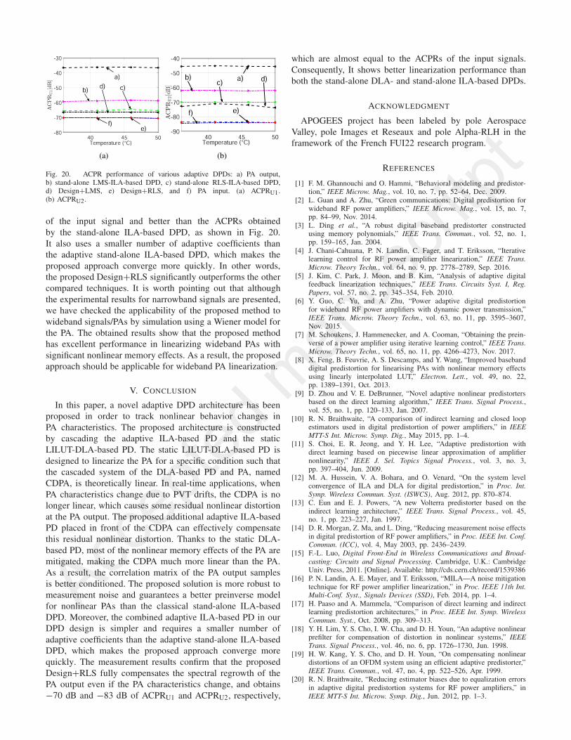
critptFig. 20. ACPR performance of various adaptive DPDs: a) PA output,
b) stand-alone LMS-ILA-based DPD, c) stand-alone RLS-ILA-based DPD,d) Design+LMS, e) Design+RLS, and f) PA input. (a) ACPRU1.(b) ACPRU2.
of the input signal and better than the ACPRs obtainedby the stand-alone ILA-based DPD, as shown in Fig. 20.It also uses a smaller number of adaptive coefficients thanthe adaptive stand-alone ILA-based DPD, which makes theproposed approach converge more quickly. In other words,the proposed Design+RLS significantly outperforms the othercompared techniques. It is worth pointing out that althoughthe experimental results for narrowband signals are presented,we have checked the applicability of the proposed method towideband signals/PAs by simulation using a Wiener model forthe PA. The obtained results show that the proposed methodhas excellent performance in linearizing wideband PAs withsignificant nonlinear memory effects. As a result, the proposedapproach should be applicable for wideband PA linearization.
V. CONCLUSION
In this paper, a novel adaptive DPD architecture has beenproposed in order to track nonlinear behavior changes inPA characteristics. The proposed architecture is constructedby cascading the adaptive ILA-based PD and the staticLILUT-DLA-based PD. The static LILUT-DLA-based PD isdesigned to linearize the PA for a specific condition such thatthe cascaded system of the DLA-based PD and PA, namedCDPA, is theoretically linear. In real-time applications, whenPA characteristics change due to PVT drifts, the CDPA is nolonger linear, which causes some residual nonlinear distortionat the PA output. The proposed additional adaptive ILA-basedPD placed in front of the CDPA can effectively compensatethis residual nonlinear distortion. Thanks to the static DLA-based PD, most of the nonlinear memory effects of the PA aremitigated, making the CDPA much more linear than the PA.As a result, the correlation matrix of the PA output samplesis better conditioned. The proposed solution is more robust tomeasurement noise and guarantees a better preinverse modelfor nonlinear PAs than the classical stand-alone ILA-basedDPD. Moreover, the combined adaptive ILA-based PD in ourDPD design is simpler and requires a smaller number ofadaptive coefficients than the adaptive stand-alone ILA-basedDPD, which makes the proposed approach converge morequickly. The measurement results confirm that the proposedDesign+RLS fully compensates the spectral regrowth of thePA output even if the PA characteristics change, and obtains−70 dB and −83 dB of ACPRU1 and ACPRU2, respectively,
which are almost equal to the ACPRs of the input signals.Consequently, It shows better linearization performance thanboth the stand-alone DLA- and stand-alone ILA-based DPDs.
ACKNOWLEDGMENT
APOGEES project has been labeled by pole AerospaceValley, pole Images et Reseaux and pole Alpha-RLH in theframework of the French FUI22 research program.
REFERENCES
[1] F. M. Ghannouchi and O. Hammi, “Behavioral modeling and predistor-tion,” IEEE Microw. Mag., vol. 10, no. 7, pp. 52–64, Dec. 2009.
[2] L. Guan and A. Zhu, “Green communications: Digital predistortion forwideband RF power amplifiers,” IEEE Microw. Mag., vol. 15, no. 7,pp. 84–99, Nov. 2014.
[3] L. Ding et al., “A robust digital baseband predistorter constructedusing memory polynomials,” IEEE Trans. Commun., vol. 52, no. 1,pp. 159–165, Jan. 2004.
[4] J. Chani-Cahuana, P. N. Landin, C. Fager, and T. Eriksson, “Iterativelearning control for RF power amplifier linearization,” IEEE Trans.Microw. Theory Techn., vol. 64, no. 9, pp. 2778–2789, Sep. 2016.
[5] J. Kim, C. Park, J. Moon, and B. Kim, “Analysis of adaptive digitalfeedback linearization techniques,” IEEE Trans. Circuits Syst. I, Reg.Papers, vol. 57, no. 2, pp. 345–354, Feb. 2010.
[6] Y. Guo, C. Yu, and A. Zhu, “Power adaptive digital predistortionfor wideband RF power amplifiers with dynamic power transmission,”IEEE Trans. Microw. Theory Techn., vol. 63, no. 11, pp. 3595–3607,Nov. 2015.
[7] M. Schoukens, J. Hammenecker, and A. Cooman, “Obtaining the prein-verse of a power amplifier using iterative learning control,” IEEE Trans.Microw. Theory Techn., vol. 65, no. 11, pp. 4266–4273, Nov. 2017.
[8] X. Feng, B. Feuvrie, A. S. Descamps, and Y. Wang, “Improved basebanddigital predistortion for linearising PAs with nonlinear memory effectsusing linearly interpolated LUT,” Electron. Lett., vol. 49, no. 22,pp. 1389–1391, Oct. 2013.
[9] D. Zhou and V. E. DeBrunner, “Novel adaptive nonlinear predistortersbased on the direct learning algorithm,” IEEE Trans. Signal Process.,vol. 55, no. 1, pp. 120–133, Jan. 2007.
[10] R. N. Braithwaite, “A comparison of indirect learning and closed loopestimators used in digital predistortion of power amplifiers,” in IEEEMTT-S Int. Microw. Symp. Dig., May 2015, pp. 1–4.
[11] S. Choi, E. R. Jeong, and Y. H. Lee, “Adaptive predistortion withdirect learning based on piecewise linear approximation of amplifiernonlinearity,” IEEE J. Sel. Topics Signal Process., vol. 3, no. 3,pp. 397–404, Jun. 2009.
[12] M. A. Hussein, V. A. Bohara, and O. Venard, “On the system levelconvergence of ILA and DLA for digital predistortion,” in Proc. Int.Symp. Wireless Commun. Syst. (ISWCS), Aug. 2012, pp. 870–874.
[13] C. Eun and E. J. Powers, “A new Volterra predistorter based on theindirect learning architecture,” IEEE Trans. Signal Process., vol. 45,no. 1, pp. 223–227, Jan. 1997.
[14] D. R. Morgan, Z. Ma, and L. Ding, “Reducing measurement noise effectsin digital predistortion of RF power amplifiers,” in Proc. IEEE Int. Conf.Commun. (ICC), vol. 4, May 2003, pp. 2436–2439.
[15] F.-L. Luo, Digital Front-End in Wireless Communications and Broad-casting: Circuits and Signal Processing. Cambridge, U.K.: CambridgeUniv. Press, 2011. [Online]. Available: http://cds.cern.ch/record/1539386
[16] P. N. Landin, A. E. Mayer, and T. Eriksson, “MILA—A noise mitigationtechnique for RF power amplifier linearization,” in Proc. IEEE 11th Int.Multi-Conf. Syst., Signals Devices (SSD), Feb. 2014, pp. 1–4.
[17] H. Paaso and A. Mammela, “Comparison of direct learning and indirectlearning predistortion architectures,” in Proc. IEEE Int. Symp. WirelessCommun. Syst., Oct. 2008, pp. 309–313.
[18] Y. H. Lim, Y. S. Cho, I. W. Cha, and D. H. Youn, “An adaptive nonlinearprefilter for compensation of distortion in nonlinear systems,” IEEETrans. Signal Process., vol. 46, no. 6, pp. 1726–1730, Jun. 1998.
[19] H. W. Kang, Y. S. Cho, and D. H. Youn, “On compensating nonlineardistortions of an OFDM system using an efficient adaptive predistorter,”IEEE Trans. Commun., vol. 47, no. 4, pp. 522–526, Apr. 1999.
[20] R. N. Braithwaite, “Reducing estimator biases due to equalization errorsin adaptive digital predistortion systems for RF power amplifiers,” inIEEE MTT-S Int. Microw. Symp. Dig., Jun. 2012, pp. 1–3.
Accep
ted m
anus
critpt
[21] P. M. Suryasarman and A. Springer, “A comparative analysis of adaptivedigital predistortion algorithms for multiple antenna transmitters,” IEEETrans. Circuits Syst. I, Reg. Papers, vol. 62, no. 5, pp. 1412–1420,May 2015.
[22] X. Feng, B. Feuvrie, A. S. Descamps, and Y. Wang, “A digital predis-tortion method based on nonuniform memory polynomial model usinginterpolated LUT,” in Proc. IEEE Top. Conf. Power Amplif. WirelessRadio Appl. (PAWR), Jan. 2015, pp. 1–3.
[23] J. Kim and K. Konstantinou, “Digital predistortion of wideband signalsbased on power amplifier model with memory,” Electron. Lett., vol. 37,no. 23, pp. 1417–1418, Nov. 2001.
[24] A. E. Abdelrahman, O. Hammi, A. K. Kwan, A. Zerguine, andF. M. Ghannouchi, “A novel weighted memory polynomial for behav-ioral modeling and digital predistortion of nonlinear wireless trans-mitters,” IEEE Trans. Ind. Electron., vol. 63, no. 3, pp. 1745–1753,Mar. 2016.
[25] E. Cottais, Y. Wang, and S. Toutain, “A new adaptive baseband digitalpredistortion technique,” in Proc. Eur. Microw. Assoc., vol. 2, Jun. 2006,pp. 154–159.
[26] F. Li, B. Feuvrie, Y. Wang, and W. Chen, “MP/LUT baseband digitalpredistorter for wideband linearisation,” Electron. Lett., vol. 47, no. 19,pp. 1096–1098, Sep. 2011.
[27] A. Hekkala et al., “Predistortion of radio over fiber links: Algorithms,implementation, and measurements,” IEEE Trans. Circuits Syst. I, Reg.Papers, vol. 59, no. 3, pp. 664–672, Mar. 2012.
[28] A. V. Oppenheim and R. W. Schafer, Digital Signal Processing.Upper Saddle River, NJ, USA: Prentice-Hall, 2006.
[29] S. Haykin, Adaptive Filter Theory. Upper Saddle River, NJ, USA:Prentice-Hall, 2002.
[30] T. Liu, S. Boumaiza, and F. M. Ghannouchi, “Deembedding staticnonlinearities and accurately identifying and modeling memory effectsin wide-band RF transmitters,” IEEE Trans. Microw. Theory Techn.,vol. 53, no. 11, pp. 3578–3587, Nov. 2005.
[31] L. Ding and G. T. Zhou, “Effects of even-order nonlinear terms onpower amplifier modeling and predistortion linearization,” IEEE Trans.Veh. Technol., vol. 53, no. 1, pp. 156–162, Jan. 2004.
[32] X. Feng, “Efficient baseband digital predistortion techniques for lineariz-ing power amplifier by taking into account nonlinear memory effect,”Ph.D. dissertation, Univ. Nantes, Nantes, France, Sep. 2015. [Online].Available: https://hal.archives-ouvertes.fr/tel-01206266
[33] X. Feng, Y. Wang, B. Feuvrie, A.-S. Descamps, Y. Ding, and Z. Yu,“Analysis on LUT based digital predistortion using direct learningarchitecture for linearizing power amplifiers,” EURASIP J. WirelessCommun. Netw., vol. 2016, no. 1, p. 132, Dec. 2016. [Online]. Available:https://doi.org/10.1186/s13638-016-0628-y