An Accurate Illumination Model for Objects Coated with Multilayer ...
9
EUROGRAPHICS 2000 / A. de Sousa, J.C. Torres Short Presentations An Accurate Illumination Model for Objects Coated with Multilayer Films H. Hirayama, † K. Kaneda, † H. Yamashita, † and Y. Monden ‡ † Faculty of Engineering, Hiroshima University, Japan ‡ Interdisciplinary Faculty of Science and Engineering, Shimane University, Japan Abstract This paper proposes an accurate illumination model for rendering objects coated with multilayer films. Optical phenomenaof multilayer films are caused by reflection, refraction, interference, and absorption of light inside each layer of multiple films, and these physical phenomena are complicatedly related with each other. The proposed method calculates composite reflectance and transmittance of multilayer films, taking into account all the physical phenomena described above, and visualizes the optical phenomena caused by the multilayer films accurately. The illumination model proposed in the paper can handle both smooth surface and locally smooth rough surfaces. Several examples of objects coated with various kinds of films demonstrate the usefulness of the proposed method. 1. Introduction It happens so frequently to see optical effects caused by mul- tilayer thin films in our daily lives, and the effects are so exquisite. For examples, rainbow colors appear on the sur- face inside a sea shell or on a multi-coated lens of glasses, and the color changes greatly, depending on the viewing di- rection and wavelength of light. Such optical phenomena of multilayer films are caused by reflection, refraction, inter- ference, and absorption of light inside each layer of multiple films, and these physical phenomena are complicatedly re- lated with each other. Diffraction 1 has similar optical effects to those of the thin films. Rainbow colors appear on a diffraction grating 2 and the surface of a compact disk 3 . The effects also originate from interference of light, but the path of the light ray which causes interference is quite different. In diffraction, trans- mitted light from a grating or reflected light from a dumpy surface interacts with each other, while in multilayer films, both reflected and refracted of light from each boundary of layers of films interact with each other. The process of inter- ference of light inside multilayer films is more complicated. Multilayer films are also used in industry, for example, optical lenses and filters for optical equipments, window- panes of buildings, and so on. They are designed to have a good optical efficiency or a pleasant appearance. Traditional methods for evaluating the optical properties of films, such as graphs of reflectance and transmittance of the films, are not helpful for better understanding the properties of multi- layer films, as the properties change considerably depending on both direction and wavelength of light. Therefore, it is desired to visualize optical effects of multilayer films in the design process. 2. Related work Methods for rendering optical phenomena caused by thin films or layered objects have been developed since 1990. These illumination models for rendering films are classified into four types (see Fig. 1): Single-layer Film Primary Re- flection and refraction (SFPR), Single-layer Film Multiple Reflection and refraction (SFMR), Multilayer Film Primary Reflection and refraction (MFPR), and Multilayer Film Mul- tiple Reflection and refraction (MFMR). The simplest illumination model is a SFPR model, which can render optical effects of a single layer film, such as soap bubbles 4 and Newton’s ring 5 , taking into account only pri- mary reflection and refraction. The illumination model, how- ever, has limitation both in objects and accuracy. A more accurate model for a single layer film is a SFMR model. In the illumination model, multiple reflection and re- fraction are taken into account, and soap bubbles 6, 7 , optical c The Eurographics Association 2000.
-
Upload
truonghuong -
Category
Documents
-
view
217 -
download
1
Transcript of An Accurate Illumination Model for Objects Coated with Multilayer ...

EUROGRAPHICS 2000 / A. de Sousa, J.C. Torres Short Presentations
An Accurate Illumination Model for Objects Coated withMultilayer Films
H. Hirayama,† K. Kaneda,† H. Yamashita,† and Y. Monden‡
†Faculty of Engineering, Hiroshima University, Japan‡Interdisciplinary Faculty of Science and Engineering, Shimane University, Japan
Abstract
This paper proposes an accurate illumination model for rendering objects coated with multilayer films. Opticalphenomenaof multilayer films are caused by reflection, refraction, interference, and absorption of light inside eachlayer of multiple films, and these physical phenomena are complicatedly related with each other. The proposedmethod calculates composite reflectance and transmittance of multilayer films, taking into account all the physicalphenomena described above, and visualizes the optical phenomena caused by the multilayer films accurately. Theillumination model proposed in the paper can handle both smooth surface and locally smooth rough surfaces.Several examples of objects coated with various kinds of films demonstrate the usefulness of the proposed method.
1. Introduction
It happens so frequently to see optical effects caused by mul-tilayer thin films in our daily lives, and the effects are soexquisite. For examples, rainbow colors appear on the sur-face inside a sea shell or on a multi-coated lens of glasses,and the color changes greatly, depending on the viewing di-rection and wavelength of light. Such optical phenomena ofmultilayer films are caused by reflection, refraction, inter-ference, and absorption of light inside each layer of multiplefilms, and these physical phenomena are complicatedly re-lated with each other.
Diffraction1 has similar optical effects to those of the thinfilms. Rainbow colors appear on a diffraction grating2 andthe surface of a compact disk3. The effects also originatefrom interference of light, but the path of the light ray whichcauses interference is quite different. In diffraction, trans-mitted light from a grating or reflected light from a dumpysurface interacts with each other, while in multilayer films,both reflected and refracted of light from each boundary oflayers of films interact with each other. The process of inter-ference of light inside multilayer films is more complicated.
Multilayer films are also used in industry, for example,optical lenses and filters for optical equipments, window-panes of buildings, and so on. They are designed to have agood optical efficiency or a pleasant appearance. Traditional
methods for evaluating the optical properties of films, suchas graphs of reflectance and transmittance of the films, arenot helpful for better understanding the properties of multi-layer films, as the properties change considerably dependingon both direction and wavelength of light. Therefore, it isdesired to visualize optical effects of multilayer films in thedesign process.
2. Related work
Methods for rendering optical phenomena caused by thinfilms or layered objects have been developed since 1990.These illumination models for rendering films are classifiedinto four types (see Fig. 1): Single-layer Film Primary Re-flection and refraction (SFPR), Single-layer Film MultipleReflection and refraction (SFMR), Multilayer Film PrimaryReflection and refraction (MFPR), and Multilayer Film Mul-tiple Reflection and refraction (MFMR).
The simplest illumination model is a SFPR model, whichcan render optical effects of a single layer film, such as soapbubbles4 and Newton’s ring5, taking into account only pri-mary reflection and refraction. The illumination model, how-ever, has limitation both in objects and accuracy.
A more accurate model for a single layer film is a SFMRmodel. In the illumination model, multiple reflection and re-fraction are taken into account, and soap bubbles6, 7, optical
c© The Eurographics Association 2000.
H. Hirayama, et al. / An Accurate Illumination Model for Objects Coated with Multilayer Films
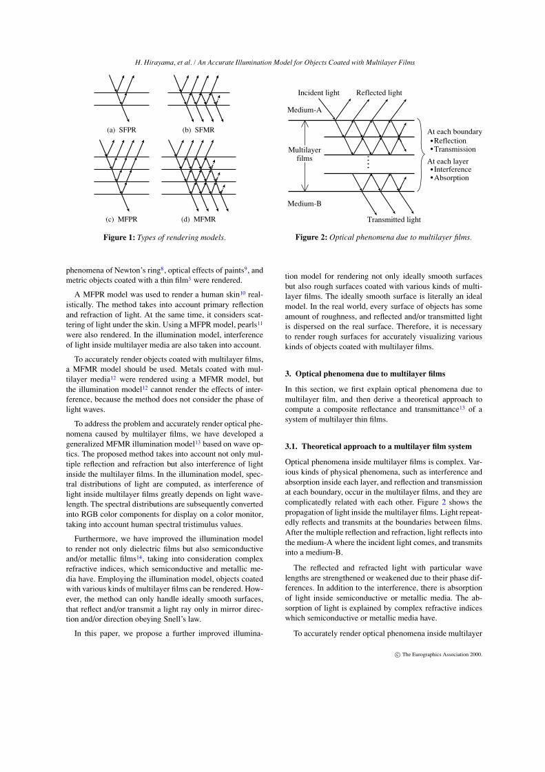
(a) SFPR (b) SFMR
(c) MFPR (d) MFMR
Figure 1: Types of rendering models.
phenomena of Newton’s ring8, optical effects of paints9, andmetric objects coated with a thin film3 were rendered.
A MFPR model was used to render a human skin10 real-istically. The method takes into account primary reflectionand refraction of light. At the same time, it considers scat-tering of light under the skin. Using a MFPR model, pearls11
were also rendered. In the illumination model, interferenceof light inside multilayer media are also taken into account.
To accurately render objects coated with multilayer films,a MFMR model should be used. Metals coated with mul-tilayer media12 were rendered using a MFMR model, butthe illumination model12 cannot render the effects of inter-ference, because the method does not consider the phase oflight waves.
To address the problem and accurately render optical phe-nomena caused by multilayer films, we have developed ageneralized MFMR illumination model13 based on wave op-tics. The proposed method takes into account not only mul-tiple reflection and refraction but also interference of lightinside the multilayer films. In the illumination model, spec-tral distributions of light are computed, as interference oflight inside multilayer films greatly depends on light wave-length. The spectral distributions are subsequently convertedinto RGB color components for display on a color monitor,taking into account human spectral tristimulus values.
Furthermore, we have improved the illumination modelto render not only dielectric films but also semiconductiveand/or metallic films14, taking into consideration complexrefractive indices, which semiconductive and metallic me-dia have. Employing the illumination model, objects coatedwith various kinds of multilayer films can be rendered. How-ever, the method can only handle ideally smooth surfaces,that reflect and/or transmit a light ray only in mirror direc-tion and/or direction obeying Snell’s law.
In this paper, we propose a further improved illumina-
Incident light Reflected light
Transmitted light
ReflectionTransmission
At each boundary
At each layerInterferenceAbsorption
Medium-A
Medium-B
Multilayerfilms
Figure 2: Optical phenomena due to multilayer films.
tion model for rendering not only ideally smooth surfacesbut also rough surfaces coated with various kinds of multi-layer films. The ideally smooth surface is literally an idealmodel. In the real world, every surface of objects has someamount of roughness, and reflected and/or transmitted lightis dispersed on the real surface. Therefore, it is necessaryto render rough surfaces for accurately visualizing variouskinds of objects coated with multilayer films.
3. Optical phenomena due to multilayer films
In this section, we first explain optical phenomena due tomultilayer film, and then derive a theoretical approach tocompute a composite reflectance and transmittance13 of asystem of multilayer thin films.
3.1. Theoretical approach to a multilayer film system
Optical phenomena inside multilayer films is complex. Var-ious kinds of physical phenomena, such as interference andabsorption inside each layer, and reflection and transmissionat each boundary, occur in the multilayer films, and they arecomplicatedly related with each other. Figure 2 shows thepropagation of light inside the multilayer films. Light repeat-edly reflects and transmits at the boundaries between films.After the multiple reflection and refraction, light reflects intothe medium-A where the incident light comes, and transmitsinto a medium-B.
The reflected and refracted light with particular wavelengths are strengthened or weakened due to their phase dif-ferences. In addition to the interference, there is absorptionof light inside semiconductive or metallic media. The ab-sorption of light is explained by complex refractive indiceswhich semiconductive or metallic media have.
To accurately render optical phenomena inside multilayer
c© The Eurographics Association 2000.

H. Hirayama, et al. / An Accurate Illumination Model for Objects Coated with Multilayer Films
Incidentlight Reflected
light
Transmittedlight
Composite reflectance
Composite transmittance
Multilayer film system
ReflectionTransmission
InterferenceAbsorption
Taking into account:
Input Output
Output
Figure 3: Theoretical approach of a multilayer film system.
films, it needs a huge computation cost to trace all rays in-side the films taking into account the phenomena describedabove. To solve the problem, multilayer films are consideredto be a single input-output system, and specific coefficientsexpressing the input-output relationship of the system calcu-lated using coefficients of each layer (see Fig. 3). That is, acomposite reflectance and transmittance of a multilayer filmsystem are calculated from reflectivities and transmissivitiesof each boundary between films, taking into account inter-ference and absorption of light inside each layer. This the-oretical approach makes it possible to accurately visualizeoptical phenomena inside multilayer films. Next, we discussa method for computing the composite reflectance and trans-mittance.
3.2. A method for calculating composite reflectance andtransmittance13
We consider a (N + 2) layered film system (see Fig. 4), thatis, there is a N layers of films between two media. Incidentlight from the medium-A is reflected back into the medium-A and transmitted into medium-B. Preconditions of a mul-tilayer film systems in the proposed method are as follows.
1. Each boundary is parallel to xy-plane and smooth. Forthis precondition, light is reflected in only a mirror direc-tion and transmitted in only a direction obeying Snell’slaw at each boundary.
2. Each layer is a homogeneous and isotropic medium, thatis, a refractive index of each layer is constant.
3. Light comes in parallel to the zx-plane from medium-A.A refractive index of medium-A should be a real value,i.e., there is no absorption in the medium from whichlight comes.
According to these preconditions, a composite reflectance,γN , and transmittance, τN , of the (N +2) layered film system
x
z
(0th Layer)
j
n 0
j-1
N
N+1
Nγ
γN-j
γ0
γN-j+ 1
τ0
τN-j
τ
Nτr1
t 1
r j
t j
r j+1
t j+1
t N+1
rN+1
n
n
n
nN-j+ 1
1n
nn :
:complex reflactive indexreal reflective index
θ i : incident angle of light γN-j
τN-j
rj+1
t j+1
::::
transmissivity at boundaryreflectivity at boundary
composite reflectivity composite transmissivity
ϕ j : phase difference
ϕ j
Transmitted light
Incident light Reflected light
Medium-A
Medium-B
N-th Layer
j-th Layer
j-1th Layer
1th Layer
θr : reflected angle of lightθ t : transmitted angle of light
θ i θr
θ t
(N+1th Layer)
N-Layeredfilm
Figure 4: Multilayer film system.
are calculated by an iterative method from the last layer tothe first13 (see Appendix A).
• Seed Eqs. (for j = N +1)
γ0 = r j = rN+1, (1)
τ0 = t j = tN+1. (2)
• Recurrence Eqs. (for j = N, · · ·,1)
γN− j+1 =r j + γN− j e2iϕ j
1+ r j γN− j e2iϕ j, (3)
τN− j+1 =t jτN− j eiϕ j
1+ r j γN− j e2iϕ j, (4)
where i denotes an imaginary number, r j and t j are the re-flectivity and transmissivity at a boundary between ( j−1)thand j-th layers, respectively, and these coefficients are ob-tained by Fresnel formulae. ϕ j is the phase difference be-tween boundaries of j-th layer. γN− j and τN− j are the com-posite reflectivity and transmissivity at a boundary betweenj-th and (N +1)th layers, respectively.
The reflectivity and transmissivity represent ratios of am-plitudes of reflected and transmitted electromagnetic waves,respectively. On the other hand, the reflectance and transmit-tance represent ratios of energies of reflected and transmittedlight, respectively, and they are obtained by square of an ab-solute value of the reflectivity and transmissivity. Finally, acomposite reflectance, kr, and transmittance, kt , of the multi-layer film system are calculated by averaging the energies ofthe parallel (‖) and perpendicular (⊥) components, becausethe contributions of these two components to the reflectance
c© The Eurographics Association 2000.

H. Hirayama, et al. / An Accurate Illumination Model for Objects Coated with Multilayer Films
NViewing ray
θr θi
θt
Medium-A
InterferenceAbsorptionTransmittance
Reflectance
Ideal smooth surface
Reflected ray
Transmitted ray
TransmittanceReflectance
Medium-B
kr
k t
k’rk’t
I t
IeIr
Figure 5: Ideally smooth surface coated with multilayerfilms.
and transmittance are usually equal.
kr =12
(∣∣∣γ‖,N
∣∣∣2 +∣∣γ⊥,N
∣∣2) , (5)
kt =
nN+1 cosθt
n0 cosθi
[12
(∣∣∣τ‖,N
∣∣∣2+∣∣τ⊥,N
∣∣2)](nN+1 : real)
0 (nN+1 : complex),
(6)
where n0 and nN+1 denote refractive indices of 0th and N-thlayers, respectively, and the other arguments are illustratedin Fig. 4.
4. Illumination model
In this section, we discuss an illumination model to accu-rately render objects coated with multilayer films, taking intoaccount multiple reflection, interference, and absorption oflight. The illumination model consists of two kinds of mod-els, depending on reflection properties of object surfaces onwhich multilayer films are coated: Ideally smooth and lo-cally smooth rough surfaces (LSRS type)15.
4.1. Ideally smooth surfaces
In this type of surfaces, the proposed method described inSec. 3.2 can be directly used to calculate a composite re-flectance and transmittance, because all boundary surfacesconsisting of multilayer film system are smooth. Therefore,the equation of the illumination model is expressed as fol-lows (see Fig. 5).
Ie(λ) = kr(θi,λ) Ir(λ) +kt(θi,λ) It(λ), (7)
where Ie , Ir , and It indicate intensities of an viewing, re-flected, and transmitted rays, respectively. θi is an incidentangle of the viewing ray, and λ is wave length of light. kr
and kt are a reflectance and transmittance of the multilayerfilm system obtained by the composite reflectance and trans-mittance calculation described in Eqs. 5 and 6. Note that wecan use a forward transmittance, kt(θi,λ), in Eq. 7, as the
N Viewing rayReflected ray
Multilayerfilms
NLight source
θ l
(a) Global illumination component (b) Local illumination component
Rough surface
Average plne
θr θiI eI r
Specular component- Multiple refleciton- Interference- Absorption
Specular component- Multiple refleciton- Interference- Absorption
Diffuse component- Interference- Absorption
Viewing rayI eθi
ωiωr ωiωl
Lm
Figure 6: Rough surfaces coated with multilayer films.
forward transmittance is equivalent to the backward trans-mittance, k′t(θt ,λ), because of the energy conservation law.
4.2. Rough surfaces
Rough surfaces consist of micro facets, and these surfacesare gentle roughness slopes. Multilayer films coated on thesurface have still smooth boundaries between films becausewe assume that the bump of the rough surface is quite smallcompared with the extent of the surface. Thickness of a layeradjoined by the rough surfaces is approximated by averagingheight of the micro facets. The equation of the illuminationmodel is expressed as follows.
Ie(λ) = kr(θi,λ)Ir(λ) +M
∑m=1
kd(→ωl ,
→ω i,λ)cosθlLm(λ),
(8)
where kd is a diffuse reflection coefficient including direc-
tional and uniform diffuse components,→ω represents a di-
rection of (θ,φ), and Lm denotes an intensity of each lightsource (m = 1, · · · ,M; M is the number of light sources). Thefirst and second terms express global and local illuminationcomponents, respectively (see Fig. 6).
For global illumination components, their intensities arecalculated by tracing a reflected ray recursively and multi-plying specular reflectances, kr, at each intersection point.The composite specular reflectivity, γs,N , of a rough surfacecoated with multilayer films is calculated by the followingseed and recurrence equations.
γs,0 = η(→ωi,N ,
→ω i,N ,λ), (9)
γs,N− j+1 =r j(θi, j−1,λ)+ γN− j (θi, j,λ)e2iϕ j(θi, j ,λ)
1+ r j(θi, j−1,λ) γN− j(θi, j ,λ)e2iϕ j(θi, j,λ) (10)
(for j = N, · · ·,1),
where η expresses a ratio of amplitude of electromagneticwaves taking into account roughness of object surfaces, anddepends on both directions of an incident and reflected light.
c© The Eurographics Association 2000.

H. Hirayama, et al. / An Accurate Illumination Model for Objects Coated with Multilayer Films
: Amplitude of light sourceEl
: Amplitude of viewing rayEe
: Amplitude of reflected lightEr
: incident angle of lightθ l
: viewing angleθ i
: reflectivity at rough boundaryηr : reflectivity at ideal smooth boundaryt : transmissivity at ideal smooth boundaryγ : composite reflectivity ϕ : phase difference
NLight source 1st reflected lightEl
Rough surface
Layer 1
Layer 0
η η
ϕ l,1
η
r, t
ϕ ,l ϕi γdγ ,s
Er
Ee
Er
Ee
Er
(a) Light propagations (b) Notations
2nd reflected light
Viewing ray
0th reflected light
Viewing ray
(0)
(1)
(1)
(2)
(2)θl,0 θr,0θi,0
i,0ωr,0ωl,0ω r,0ω r,0ωi,0ω
θi,0θr,0 θr,0
ϕi,1 ϕi,1
ϕ l,1 ϕ l,1 ϕ l,1
Figure 7: Specular and diffuse component of light.
Finally, the specular reflectance, kr, is obtained from a com-posite reflectivity, γs,N , using Eq. 5. For the specular re-flectance of rough surfaces, multiple reflections, interfer-ence, and absorption of light inside all layers are taken intoaccount.
To calculate the diffuse reflectance, kd , we assume the fol-lowing model. As shown in Fig. 7, a locally smooth roughsurface is coat with a single layer, and light is reflected to-ward a viewpoint. A specular component of light inside thelayer is reflected repeatedly on the both boundaries, that is,multiple reflections of a specular component should be takeninto account. On the other hand, a diffuse component is rela-tively small, compared to the specular component, and a pri-mary reflection of the diffuse component is only taken intoaccount. From the above discussion, amplitudes of the re-flected light into the viewing direction as follows.
Ee =∞∑
m=1ΓΛm−1El, (11)
where,
Λ = −r(θl,0,λ)η(→ωl,1 ,
→ω l,1 ,λ)e2iϕl,1(θl,1,λ), (12)
Γ =n̂1sz,1
n̂0sz,0t(θi,0,λ)t(θl,0,λ)η(
→ωl,1,
→ω i,1,λ)Φl,1, (13)
Φl,1 = ei[ϕl,1(θl,1 ,λ)+ϕi,1(θi,1,λ)], (14)
where m denotes the number of multiple reflection, n̂ is arefractive index, and sz is a z-component of the unit vectorindicating a direction of the light propagation. From theseequations, the recurrence equations to calculate compositereflectance are obtained by the similar way to that of Eqs.3 (see Appendix A). For local illumination, a composite dif-fuse reflectivity, γd ,N, is calculated by the following seed and
recurrence equations.
γd ,0 = η(→ωl,N ,
→ω i,N ,λ), (15)
γd ,N− j+1 =Γ j
1+ r j(θl, j−1,λ)γs,N− j (θl, j ,λ)e2iϕl, j(θl, j ,λ)
(16)
(for j = N, · · ·,1),
where
Γ j =n̂ jsz, j
n̂ j−1sz, j−1t j(θi, j−1,λ)t j(θl, j−1 ,λ) ·
γd ,N− j(→ωl, j ,
→ω i, j,λ)ei[ϕl, j(θl, j−1,λ)+ϕi, j(θi, j−1,λ)], (17)
where γs is a composite specular reflectivity, and is calcu-lated by using Eqs. 9 and 10. Consequently, a diffuse re-flectance, kd , is obtained by the composite reflectivity, γd ,N ,using Eq. 5.
5. Implementation
We implemented the proposed method into a MultilayerFilm Raytracer (MFRT)13. The MFRT has been developedto accurately visualize optical phenomena due to multilayerfilms.
Composite reflectances and transmittances of multilayerfilm systems are pre-calculated by using the proposedmethod described in Sec. 4 for each sampled incident an-gle and wave length of light, and stored into tables beforethe raytracing process. In the rendering process, if a rayintersects with an object coated with films, a reflectanceand transmittance at the intersection are linearly interpolatedfrom the pre-calculated tables.
6. Examples
Figure 8 and 9 shows examples rendered by the proposedmethod. We employed a He-Torrance model16 to define re-flection properties of the rough surfaces, and the spectral dis-tribution of light sources is set to a fluorescent lamp (N)17.
c© The Eurographics Association 2000.

H. Hirayama, et al. / An Accurate Illumination Model for Objects Coated with Multilayer Films
(a) Silicon spheres (σ0 = 0 [nm]) (b) Silicon spheres (σ0 = 25 [nm]) (c) Silicon spheres (σ0 = 50 [nm])
(d) Aluminum spheres (σ0 = 0 [nm]) (e) Aluminum spheres (σ0 = 25 [nm]) (f) Aluminum spheres (σ0 = 50 [nm])
(g) Aluminum spheres (σ0 = 0 [nm]) (h) Aluminum spheres (σ0 = 25 [nm]) (i) Aluminum spheres (σ0 = 50 [nm])
Figure 8: Rough surfaces and ideally smooth surfaces coated with multilayer films.
Spheres shown in Figs. 8(a)–(c) are made of silicon, andspheres shown in Figs. 8(d)–(i) are made of aluminum. Theleft-hand sphere is coated with multilayer films, and theright-hand one is not. Parameters of the rough surfaces (rmsroughness16, σ0, and autocorrelation length16, τ) are set toσ0 =0 [nm] in Figs. 8(a), (d), and (g); σ0 =25 [nm] in Figs.8(b), (e), and (h); σ0 =50 [nm] in Figs. 8(c), (f), and (i); andτ =300 [nm] for all figures. Note that surfaces of spheresare ideally smooth when σ0 =0 [nm]. The left-hand spherein Figs. 8(a)–(f) is coated with three-layer films consistingof dielectric, silver, and dielectric layers, and the left-handsphere in Figs. 8(h)–(i) is also coated with three-layer filmsconsisting of dielectric, gold, and dielectric layers. The re-fractive index and the thickness of the dielectric layer are setto 1.4 and 1000 [nm], respectively. The thicknesses of thesilver and gold layers are set to 5 [nm].
Iridescent colors caused by interference and absorption oflight inside the multilayer films can be observed on the sur-faces of the left-hand spheres. Furthermore, the iridescentcolors on the rough surfaces in Figs. 8(e), (f), (h), and (i) ap-
pear more clearly than those on the ideally smooth surfacesin Figs. 8(d) and (g). This is because reflected light fromthe rough surfaces is weaker than that of the ideally smoothsurfaces due to the roughness, and the iridescent colors areemphasized.
In Fig. 9, a teapot, a cylinder, and a sphere are made ofaluminum, silicon, and copper, respectively. The surfaces ofobjects in Fig. 9(a) are ideally smooth surfaces, while thosein Fig. 9(b) are rough surfaces. Table 1 shows a specifica-tion of multilayer films and parameters of roughnessused foreach object in Fig. 9. The iridescent colors on the rough sur-faces appear more clearly than those on the ideally smoothsurfaces.
The size of the rendered images in Fig. 9 is 800×533 pix-els, and it took 100 minutes to render each image with 2×2super sampling per a pixel on a Pentium II CPU (450MHz).
Figures 8 and 9 demonstrate the usefulness of the pro-posed method for visualizing the optical phenomena caused
c© The Eurographics Association 2000.

H. Hirayama, et al. / An Accurate Illumination Model for Objects Coated with Multilayer Films
(a) Ideally smooth surfaces (b) Rough surfaces (σ0 =50 [nm], τ =300 [nm])
Figure 9: Comparison of ideally smooth surfaces and rough surfaces coated with multilayer films.
Table 1: The multilayer film systems used in Fig. 9.
The system of multilayer films (medium-A, 1st layer, 2nd layer, · · · , medium-B)
Teapot air, dielectric A (1000 [nm]), silver (5 [nm]), dielectric A (1000 [nm]), aluminum
Cylinder air, dielectric B(1000 [nm]), dielectric A(1000 [nm]), dielectric B(1000 [nm]), dielectric A(1000 [nm]), silicon
Sphere air, dielectric A (1000 [nm]), gold (5 [nm]), dielectric A (1000 [nm]), copper
dielectric A: n =1.4, dielectric B: n =2.0, (n: refractive index)
by multilayer film systems, taking into account the rough-ness of surfaces coated with the films.
7. Conclusions
We have proposed an accurate illumination model for ren-dering objects coated with multilayer films. The proposedmethod makes it possible to visualize accurate reflectanceand transmittance properties of objects coated with multi-layer films. The illumination model can handle both smoothsurface and locally smooth rough surfaces, and visualize op-tical effects caused by multilayer films, taking into accountmultiple reflection and refraction, interference and absorp-tion of light inside this films.
One of the future studies is developing a method for con-sidering the geometry of rough surfaces, that is, a rough sur-face is modeled as a bump surface instead of a smooth aver-aging surface with roughness. Developing the method, bothinterference due to multilayer films and diffraction due tobump surfaces can be rendered at the same time.
References
1. H. P. Moravec. 3d graphics and the wave theory. Proc.SIGGRAPH 81. In Computer Graphics, 15(3):289–296, 1981. 1
2. E. Nakamae, K. Kaneda, T. Okamoto, and T. Nishita.A lighting model aiming at drive simulators. Proc.SIGGRAPH 90. In Computer Graphics, 24(4):395–404, 1990. 1
3. I. Icart and D. Arques. An illumination model for asystem of isotropic substrate- isotropic thin film withidentical rough boundaries. Proc. the 10th Eurograph-ics Workshop on Rendering, pages 261–272, 1999. 1,2
4. N. Suzuki, S. Yokoi, and J. Toriwaki. Study on colorcomputation in computer graphics and it’s applicationto rendering color caused by light interference. IEICETechnical Report of Japan, 88(450):41–48, 1993. (inJapanese). 1
5. B. E. Smits and G. W. Meyer. Newton’s colors: Sim-ulating interference phenomena in realistic image syn-thesis. Proc. Eurographics Workshop on Photosimula-tion, Realism and Physics in Computer Graphics, pages185–194, 1990. 1
6. M. L. Dias. Ray tracing interference color. IEEE Com-puter Graphics and Applications, 11(2):54–60, 1991.1
7. J. Li and Q. Peng. A new illumination model for scenes
c© The Eurographics Association 2000.

H. Hirayama, et al. / An Accurate Illumination Model for Objects Coated with Multilayer Films
containing thin film interference. Chinese Journal ofElectronics, 5(1):18–24, 1996. 1
8. M. L. Dias. Ray tracing interference color: Visualizingnewton’s rings. IEEE Computer Graphics and Appli-cations, 14(3):17–20, 1994. 2
9. J. S. Gondek, G. W. Meyer, and J. G. Newman.Wavelength dependent reflectance functions. Proc.SIGGRAPH 94, pages 213–220, 1994. 2
10. P. Hanrahan and K. Wolfgang. Reflection from lay-erd surfaces due to subsurfaces scattering. Proc.SIGGRAPH 93, pages 165–174, 1993. 2
11. N. Nagata, T. Dobashi, Y. Manabe, T. Usami, andS. Inokuchi. Modeling and visualization for a pearl-quality evaluation simulator. IEEE Trans. Visualizationand Computer Graphics, 3(4):307–315, 1997. 2
12. J. Dorsey and P. Hanrahan. Modeling and rendering ofmetallic paints. Proc. SIGGRAPH 96, pages 387–396,1996. 2
13. H. Hirayama, Y. Monden, K. Kaneda, andH. Yamashita. Scientific visualization of wavescattering phenomena of transparent optical systems.The Journal of Institute of Image Electronics Engineersof Japan, 27(4):306–317, 1998. (in Japanese). 2, 3, 5
14. H. Hirayama, K. Kaneda, H. Yamashita, Y. Monden,and Y. Yamaji. Visualization of optical phenomenacaused by multilayer films with complex refractive in-dices. Proc. Pacific Graphics ’99, pages 128–137,1999. 2
15. I. Ohlidal and K. Navratil. Scattering of light from mul-tilayer systems with rough boundaries. Progress in Op-tics, 34, 1995. 4
16. X. D. He, K. E. Torrance, F. X. Sillion, and D. P.Greenberg. A comprehensive physical model for lightreflection. Proc. SIGGRAPH 91. In Computer Graph-ics, 25(4):175–186, 1991. 5, 6
17. Ed. The Illuminating Engineering Institute of Japan.Lighting Handbook. Ohmsha, 1987. (in Japanese). 5
Appendix A: Recurrence equations of compositereflectivity and transmissivity
Let’s consider a three-layer film system (see Fig. 10), wherelight comes form layer, L0, and is transmitted to layer, L2,with multiple reflection inside layer, L1. Assuming that theforward reflectivity and transmissivity at boundary, B1, arer1 and t1, respectively, and the backward reflectivity andtransmissivity, i.e., those which light travels from layer, L1to layer, L0, are r′1 and t′1, respectively, the composite reflec-tivity, γ, and transmissivity, τ, of the three-layer system are
Incident lightReflected light
Transmitted light
t 1r ,1
r ,2 t 2
r ,1’ t 1’ϕ
2L
1L
0L
2B
1B
1
s1
s0
m=0
m=0 m=1 m=2
m=1 m=2
Figure 10: The three-layer film system.
expressed as follows:
γ = r1 +∞∑
m=1t1r2
(r′1r2
)m−1t′1e2iϕ1 m, (18)
τ =∞∑
m=0t1(r2r′1
)mt2eiϕ1(2m+1), (19)
where ϕ1 is the phase difference between the boundaries oflayer, L1. Note that these equations are infinite geometricseries, because of the multiple reflection of light betweenthe boundaries of layer, L1.
Using the relationships between the forward and back-ward reflectivities/transmissivities,
γ = limm→∞
r1 +
(r2
1 +n̂1sz,1
n̂0sz,0t21
)r2 e2iϕ1
1+ r1 r2 e2iϕ1
−r2
n̂1sz,1
n̂0sz,0t21 e2iϕ1
(−r1r2 e2iϕ1
)m
1+ r1 r2 e2iϕ1, (20)
τ = limm→∞
t1t2 eiϕ1 − t1t2 eiϕ1
(−r1r2 e2iϕ1
)m
1+ r1 r2 e2iϕ1. (21)
From Fresnel formulae, the following equation is derived.
r2 +n̂1sz,1
n̂0sz,0t2 = 1. (22)
Equations 20 and 21 converge as the absolute value ofthe common ratio of the geometric series satisfies that∣∣∣r1r2e2iϕ1
∣∣∣< 1. Finally, the composite reflectivity and trans-
missivity of the three-layer film system are derived as fol-lows:
γ =r1 + r2 e2iϕ1
1+ r1 r2 e2iϕ1, τ =
t1t2 eiϕ1
1+ r1 r2 e2iϕ1. (23)
Repeating this process in order of layers from the trans-mitted light to the incident light, i.e., the inverse direction oftransmission of light, the recurrence equations (Eqs. 3 and4) are obtained.
γN− j+1 =r j + γN− j e2iϕ j
1+ r j γN− j e2iϕ j, τN− j+1 =
t jτN− j eiϕ j
1+ r j γN− j e2iϕ j.
(24)
c© The Eurographics Association 2000.

H. Hirayama, et al. / An Accurate Illumination Model for Objects Coated with Multilayer Films
c© The Eurographics Association 2000.