An AC Homopolar HTS Generator for Flywheel Energy Storage · 2018-11-21 · •Design of the HTS...
22
Robinson Research Institute CEC/ICMC 2017 10 July 2017 M1OrC-03 An AC Homopolar HTS Generator for Flywheel Energy Storage Rod Badcock 1 , Swarn Kalsi 2 , Robert Buckley 1 , James Storey 1 , and Kent Hamilton 1 1 Robinson Research Institute, Victoria University of Wellington, New Zealand 2 Kalsi Green Power Systems, 46 Renfield Dr, Princeton, NJ 08540, USA
Transcript of An AC Homopolar HTS Generator for Flywheel Energy Storage · 2018-11-21 · •Design of the HTS...

Robinson Research Institute CEC/ICMC 2017 10 July 2017 M1OrC-03
An AC Homopolar HTS Generator for Flywheel Energy Storage
Rod Badcock1, Swarn Kalsi2, Robert Buckley1, James Storey1, and Kent Hamilton1
1 Robinson Research Institute, Victoria University of Wellington, New Zealand
2 Kalsi Green Power Systems, 46 Renfield Dr, Princeton, NJ 08540, USA

Robinson Research Institute CEC/ICMC 2017 10 July 2017 M1OrC-03
Talk structure
•Background to flywheel energy storage
•Target specifications for subway systems
•Homopolar concept machines
•High Temperature Superconducting (HTS) machines
•Design of the HTS homopolar flywheel machine
•Performance calculation
•Summary

Robinson Research Institute CEC/ICMC 2017 10 July 2017 M1OrC-03
Background
• Flywheel energy storage systems (FESS) used for power averaging
• A flywheel is used as energy reservoir with an attached motor / alternator
• Possible applications for a highly efficient flywheel energy storage system include:• Dealing with intermittency. Providing ride-through for fast instantaneous
events such as demand spikes or clouds with PV.• Renewable integration. Storing during generation and extracting it during
demand;• Train systems. Extracts energy from the flywheel during acceleration and
returns the braking energy to the flywheel during deceleration;
Credit: Beacon Power Credit: Boeing Corporation Credit: Babcock Noell

Robinson Research Institute CEC/ICMC 2017 10 July 2017 M1OrC-03
Subway regenerative braking
• Regenerative braking works well when regeneration / demand spike is small
• Beijing Subway is largest electricity user in Beijing
• High train density causing stability issues (voltage on line too high / low)
• Regeneration becomes less efficient …. yet many new lines in construction
• A fast responding energy storage required for power averaging• Flywheel energy storage?
Regeneration (Credit: BART)http://www.bart.gov/news/articles/2016/news20160824
• Energy consumption:• 90% for traction
• 10 % for auxiliary supply
• Regeneration has potential to Recover 40% kinetic energy
• Modern subways usually regenerative

Robinson Research Institute CEC/ICMC 2017 10 July 2017 M1OrC-03
Target subway FESS specifications
• Station based FESS• Capacity of 500 – 1500 kW required (dependent on station)
• Modular 500 kW units selected
• High speed for size / mass minimisation
• Superconducting homopolar design selected
Parameter Value
Energy storage capability 9 MJ
Rotating machine rating 500 kW
Rotary speed 25,000 RPM
Line voltage 866 V
Rotor diameter <200 mm
Axial length of stator <500 mm
Axial length of rotor <420 mm
Overall stator coil current density <3.0 A/mm2
Maximum flux density in stator laminations <1.5 T
[

Robinson Research Institute CEC/ICMC 2017 10 July 2017 M1OrC-03
The homopolar concept
• Use a mechanically static magnet to produce rotating rotor field• Often thought to be ‘hard to understand’
• Figure shows concept
Basic Alternator Adding a yoke Extending into 3D Static HTS magnet
Robinson Research Institute CEC/ICMC 2017 10 July 2017 M1OrC-03
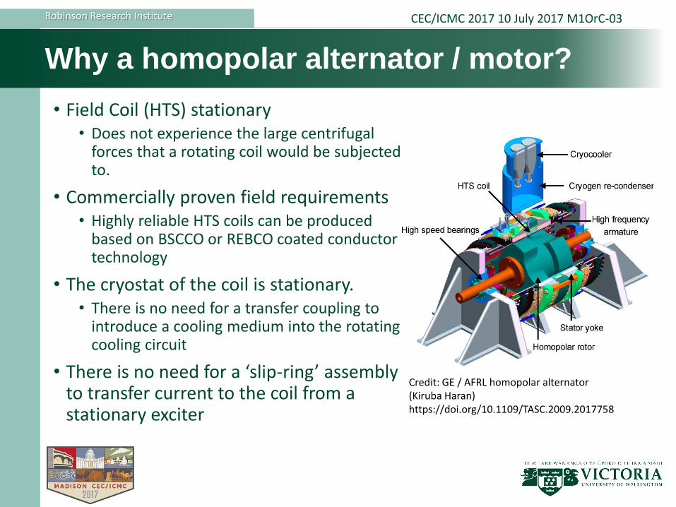
Why a homopolar alternator / motor?
• Field Coil (HTS) stationary• Does not experience the large centrifugal
forces that a rotating coil would be subjected to.
• Commercially proven field requirements• Highly reliable HTS coils can be produced
based on BSCCO or REBCO coated conductor technology
• The cryostat of the coil is stationary. • There is no need for a transfer coupling to
introduce a cooling medium into the rotating cooling circuit
• There is no need for a ‘slip-ring’ assembly to transfer current to the coil from a stationary exciter
Credit: GE / AFRL homopolar alternator (Kiruba Haran)https://doi.org/10.1109/TASC.2009.2017758

Robinson Research Institute CEC/ICMC 2017 10 July 2017 M1OrC-03
• What do we feel?• Over more than 20 years we have gone from the discovery of new HTS
materials to building machines with these materials
• This has involved understanding new materials, exploiting their properties to manufacture wire and cable and then designing, developing new HTS engineering methodologies, and then fabricating and testing prototype machines as part of an international community
• Required the international community to develop wide ranging new technologies
• The community has made significant progress in advancing HTS machines
• To assess viability we have used NASA’s well known Technology Readiness Level (TRL) approach to characterising technology development
Can we build a superconducting machine?

Robinson Research Institute CEC/ICMC 2017 10 July 2017 M1OrC-03
Technology Readiness Level (TRL) assessment
https://esto.nasa.gov/files/trl_definitions.pdf

Robinson Research Institute CEC/ICMC 2017 10 July 2017 M1OrC-03
TRL levels for HTS technologies – our opinion!
TRL for key technologies for developing HTS rotating machines
Key DC magnet technologiesCommercially mature
Key integration tech. at demonstration

Robinson Research Institute CEC/ICMC 2017 10 July 2017 M1OrC-03
Design of a HTS homopolar alternator / motor
• This machine was designed using the following assumptions; • The rotating machine is a synchronous AC homopolar type with
4-poles • The field winding is located within the stator, and wound from
HTS• Litz copper wire cable 3-phase armature winding on the stator• 0.1 mm stator laminations to reduce iron losses • The rotor is made of high permeability magnetic iron
11
Laminated
Stator
Field Coil
Armature Coils
Solid Rotor

Robinson Research Institute CEC/ICMC 2017 10 July 2017 M1OrC-03
Design of the HTS homopolar flywheel
•Homopolar machine located between two Carbon FRP flywheels• Reduces required shaft size• Halves power transfer through any one part of the shaft
•Housed in a vacuum chamber
• Supported by magnetic levitating bearings• 25,000 RPM operating speed
12
CFRP Flywheel
CFRP Flywheel

Robinson Research Institute CEC/ICMC 2017 10 July 2017 M1OrC-03
Alternator / motor armature selection
• Assuming REBCO field coil
• Two armature layouts considered• Lightweight Single Layer (SL) saddle coil layout on the left
• Conventional Double Layer (DL) layout on the right. • The coil colours signify the three phases.
• Effect of armature coil geometry on performance and specification assessed
Single Layer (SL) and Double Layer (DL) armature windings
Robinson Research Institute CEC/ICMC 2017 10 July 2017 M1OrC-03
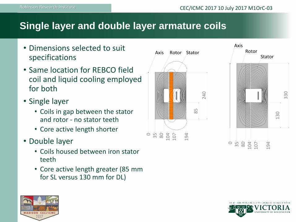
Single layer and double layer armature coils
• Dimensions selected to suit specifications
• Same location for REBCO field coil and liquid cooling employed for both
• Single layer• Coils in gap between the stator
and rotor - no stator teeth
• Core active length shorter
• Double layer• Coils housed between iron stator
teeth
• Core active length greater (85 mm for SL versus 130 mm for DL)

Robinson Research Institute CEC/ICMC 2017 10 July 2017 M1OrC-03
Impact of armature coils structure
• Double layer coils• High efficiency• Longer machine length• Greater mass• Conventional manufacture
• Single layer coils• Lighter• Shorter machine length• Slightly lower efficiency• Unconventional manufacture
• DL machine uses less ReBCO wire• 185 m for SL / 54 m for DL• Double layer machine less costly• Size and weight are not of
concern in this application
• DL design preferable
Parameter Single
Layer
Double
Layer
Power Rating, MVA 524 540
Output power at full-load, MW 519 535
Line voltage, V-rms 900 866
Phase current, A-rms 336 360
Overall axial length, m 0.32 0.46
Overall diameter, m 0.44 0.44
Mass of the machine alone, kg 345 467
Mass of cryo-cooling system, kg 30 49
Total mass, kg 375 516
Efficiency at full-load, % 98.9 99.2
STATOR WINDING DETAILS
Active length under each pole, mm 85 130
Number of armature turns/ph 20 8
Number of coils in armature 6 24
Number of turns/race coil 1 1
FIELD WINDING DETAILS
HTS wire length, m 185 22

Robinson Research Institute CEC/ICMC 2017 10 July 2017 M1OrC-03
Armature winding design
• Wave shape winding / 2 coils in series from single cable length per phase
• Litz wire single turn coils with embedded cooling tube• Equivalent to single AWG 1/0
• Only 6.7 kPa pressure drop and 1.24 K Delta T• All coils of a phase could be connected in series to form a single cooling circuit for
each phase
• Total resistive loss 1.2 kW while carrying rated load.
Parameter Value Units
Space available for Litz 100 mm2
Equivalent AWG size 1/0 Cable
Strand diameter 0.32 mm
Number of strands 665
Copper cross-section 54 mm2
Resistance of cable 0.00035 ohm/m
Resistive loss per coil 51 W
Cooling tube diameter 5 mm
Water flow velocity 1 m/s
Pressure drop 6.7 kPa
Delta T cooling tube and water 0.34 K
Temperature rise of water 1.24 K
Robinson Research Institute CEC/ICMC 2017 10 July 2017 M1OrC-03
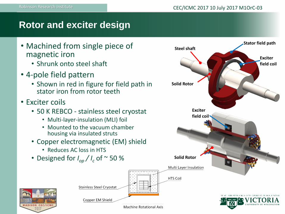
Rotor and exciter design
• Machined from single piece of magnetic iron• Shrunk onto steel shaft
• 4-pole field pattern• Shown in red in figure for field path in
stator iron from rotor teeth
• Exciter coils• 50 K REBCO - stainless steel cryostat
• Multi-layer-insulation (MLI) foil • Mounted to the vacuum chamber
housing via insulated struts
• Copper electromagnetic (EM) shield• Reduces AC loss in HTS
• Designed for Iop / Ic of ~ 50 %
Exciter
field coil
Steel shaftStator field path
Solid Rotor
Exciter
field coil
Solid Rotor
Robinson Research Institute CEC/ICMC 2017 10 July 2017 M1OrC-03
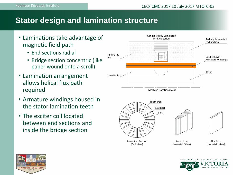
Stator design and lamination structure
• Laminations take advantage of magnetic field path• End sections radial
• Bridge section concentric (like paper wound onto a scroll)
• Lamination arrangement allows helical flux path required
• Armature windings housed in the stator lamination teeth
• The exciter coil located between end sections and inside the bridge section
Robinson Research Institute CEC/ICMC 2017 10 July 2017 M1OrC-03
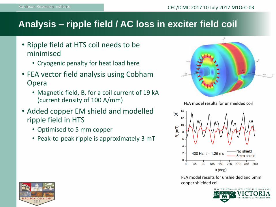
Analysis – ripple field / AC loss in exciter field coil
• Ripple field at HTS coil needs to be minimised• Cryogenic penalty for heat load here
• FEA vector field analysis using Cobham Opera• Magnetic field, B, for a coil current of 19 kA
(current density of 100 A/mm)
• Added copper EM shield and modelled ripple field in HTS• Optimised to 5 mm copper
• Peak-to-peak ripple is approximately 3 mT
FEA model results for unshielded coil
FEA model results for unshielded and 5mm copper shielded coil

Robinson Research Institute CEC/ICMC 2017 10 July 2017 M1OrC-03
Calculated performance
• Performance calculated at full-load current of 360 A• at a power-factor of 0.99 lagging
• Nominal shaft torque is 208 Nm• Short-circuit torque of 1487 Nm
• Design required that delivers a safety factor of at least 2 on short-circuit torque
• Using a refrigerator COP of 21 at 50 K, losses calculated• Total loss at full-load is 4.4 kW, which
yields an efficiency of 99.2%
• No-load loss dominated by HTS and refrigerator COP
Performance
Rated line voltage 866 V
Rated current 360 A
Power rating 540 kVA
Field current - no-load 282 A
Power factor at full-load-lagging 0.99
Field current - full-load 317 A
Load angle at full-load 1.3 °
Induced voltage at full-load 1.14 pu
Power generated at full-load 1.01 pu
Torque on armature at full-load 208 Nm
Torque on armature during a short-circuit 1487 Nm
Attractive force between rotor and stator
- Under a salient pole 9282 N
- Under non-salient pole 246 N
Losses at full-load
Stator iron core loss 1.7 kW
Armature resistive loss 1.2 kW
Armature cooling system power 0.13 kW
Field winding cooler power 1.37 kW
Refrigerator Coefficient of Performance (COP) 21
Total losses at full-load 4.45 kW
Efficiency at full-load 99.2 %
Total losses at no-load 3.23 kW

Robinson Research Institute CEC/ICMC 2017 10 July 2017 M1OrC-03
Conclusions
• Double layer coil machine preferred for this application• Constructed using current technology• Reduced cost and construction time.
• Machine design looks attractive• Compact and fits within the design space allocation• Conventional armature and field winding technologies• Comparison is expected also valid for DI-BSCCO field coil
• Stator core construction is unconventional but achievable with off-the-shelf technology
• Challenges• Magnetic bearings and flywheel fabrication will present additional challenges• More detailed inputs from 3D magnetic analysis and component development
tasks
• Conclusion: This kind of machine could be highly robust and trouble free in areas where high-speed and low-mass drives are desired.

Robinson Research Institute CEC/ICMC 2017 10 July 2017 M1OrC-03
Thank you!
…… Any questions?
for details on flux pump exciters for machines see: M2OrA-02 at 10:00 on Tuesday
for details on selecting HTS materials selection see: M2OrE-02 at 3:30 on Tuesday