
AN-8205 — AMC Library Hall Interface - Fairchild · AN-8205 AMC Library Hall Interface ... A M C...
18
www.fairchildsemi.com © 2013 Fairchild Semiconductor Corporation www.fairchildsemi.com Rev. 1.0.1 • 1/9/14 AN-8205 AMC Library Hall Interface Summary The FCM8531 is an application-specific parallel-core processor for motor control that consists of an Advanced Motor Controller (AMC) processor and a MCS ® 51- compatible MCU processor. The AMC is the core processor specifically designed for motor control. It integrates a configurable processing core and peripheral circuits to perform sensorless Field-Oriented Control (FOC) motor control. System control, user interface, communication interface, and input/output interface can be programmed through the embedded MCS ® 51 for motor applications. The advantage of FCM8531‟s parallel-core processors is that the two processors can work independently and complement each other. The AMC is dedicated for motor control applications, such as motor control algorithms, PWM control, current sensing, real-time over-current protection, and motor angle calculation. The embedded MCU provides motor control commands to the AMC to control motors through a communication interface. This approach reduces software burdens and simplifies control system programs because complex motor control algorithms are executed in the AMC. Fairchild provides the Motor Control Development System (MCDS) Integrated Development Environment (IDE) and MCDS Programming Kit for users to develop software, execute In System Programming (ISP), and perform online debugging. A typical FCM8531 development environment configuration is shown in Figure 1. The application board can be a FCM8531 evaluation board or a user-defined circuit board (referred to as a “target board”). The FCM8531 evaluation board can be used with the MCDS IDE and MCDS Programming Kit offered by Fairchild to help develop products for motor applications. The MCDS IDE can be operated under the Microsoft® Windows operating system, including functions of project management, AMC library selection, register setting, and compiler / linker / debugger link to help develop software. By using the AMC library provided by Fairchild, users can more quickly and easily develop a sensorless motor drive and shorten development time of motor applications. This document is a user guide of the AMC library. For details of the MCDS IDE and MCDS Programming Kit, refer to Fairchild’s website at: http://www.fairchildsemi.com/applications/motorcontrol/bld c-pmsm-controller.html AMC Introduction The AMC is the core processor consists of several motor control modules, such as configurable processing core, PWM engine, and angle predictor. Depending on the application, the processing core can be configured with the suitable AMC library to perform different motor control algorithms, such as FOC or sensorless. FCM8531 can drive the motor with Hall sensor or sensorless libraries. The Hall-interface library is an AMC library for driving the motor with a Hall sensor. This document mainly describes usage of the Hall-Interface Library and includes control theory, configuration, files, and a firmware example. For more detailed information on the AMC library for sensorless control, please refer to the following website: http://www.fairchildsemi.com/applications/motorcontrol/bld c-pmsm-controller.html Figure 1. Typical Development Environment
-
Upload
nguyenhanh -
Category
Documents
-
view
215 -
download
1
Transcript of AN-8205 — AMC Library Hall Interface - Fairchild · AN-8205 AMC Library Hall Interface ... A M C...

www.fairchildsemi.com
© 2013 Fairchild Semiconductor Corporation www.fairchildsemi.com Rev. 1.0.1 • 1/9/14
AN-8205 AMC Library Hall Interface
Summary
The FCM8531 is an application-specific parallel-core
processor for motor control that consists of an Advanced
Motor Controller (AMC) processor and a MCS®51-
compatible MCU processor. The AMC is the core processor
specifically designed for motor control. It integrates a
configurable processing core and peripheral circuits to
perform sensorless Field-Oriented Control (FOC) motor
control. System control, user interface, communication
interface, and input/output interface can be programmed
through the embedded MCS®51 for motor applications.
The advantage of FCM8531‟s parallel-core processors is
that the two processors can work independently and
complement each other. The AMC is dedicated for motor
control applications, such as motor control algorithms,
PWM control, current sensing, real-time over-current
protection, and motor angle calculation. The embedded
MCU provides motor control commands to the AMC to
control motors through a communication interface. This
approach reduces software burdens and simplifies control
system programs because complex motor control algorithms
are executed in the AMC. Fairchild provides the Motor
Control Development System (MCDS) Integrated
Development Environment (IDE) and MCDS Programming
Kit for users to develop software, execute In System
Programming (ISP), and perform online debugging.
A typical FCM8531 development environment
configuration is shown in Figure 1. The application board
can be a FCM8531 evaluation board or a user-defined
circuit board (referred to as a “target board”). The
FCM8531 evaluation board can be used with the MCDS
IDE and MCDS Programming Kit offered by Fairchild to
help develop products for motor applications.
The MCDS IDE can be operated under the Microsoft®
Windows operating system, including functions of project
management, AMC library selection, register setting, and
compiler / linker / debugger link to help develop software.
By using the AMC library provided by Fairchild, users can
more quickly and easily develop a sensorless motor drive
and shorten development time of motor applications. This
document is a user guide of the AMC library. For details of
the MCDS IDE and MCDS Programming Kit, refer to
Fairchild’s website at:
http://www.fairchildsemi.com/applications/motorcontrol/bld
c-pmsm-controller.html
AMC Introduction
The AMC is the core processor consists of several motor
control modules, such as configurable processing core,
PWM engine, and angle predictor. Depending on the
application, the processing core can be configured with the
suitable AMC library to perform different motor control
algorithms, such as FOC or sensorless.
FCM8531 can drive the motor with Hall sensor or sensorless
libraries. The Hall-interface library is an AMC library for
driving the motor with a Hall sensor. This document mainly
describes usage of the Hall-Interface Library and includes
control theory, configuration, files, and a firmware example.
For more detailed information on the AMC library for
sensorless control, please refer to the following website:
http://www.fairchildsemi.com/applications/motorcontrol/bld
c-pmsm-controller.html
Figure 1. Typical Development Environment
mdaniels
New Logo

AN-8205 APPLICATION NOTE
© 2013 Fairchild Semiconductor Corporation www.fairchildsemi.com Rev. 1.0.1 • 1/9/14 2
Hall Interface
The Hall interface library is selected via a Project Setting
window of the MCDS IDE, as shown in Figure 2.
Figure 2. MCDS IDE: Project Setting
Control Theory
The angle predictor (see Figure 3) is the main processor of
the Hall interface library; it includes Hall signal filter,
Phase-Lock-Loop (PLL), leading angle shifter, and angle
encoder. The Hall signal filter is used to handle the Hall
signals and filter out noise on the input signals. The PLL
detects the Hall signal changes in every 60-degree of
electrical angle to predict the rotor position. The angle
encoder sums the PLL results and leading angle shifter
setting into one angle, then the PWM engine outputs PWM
signals according to the angle of the angle encoder. For
more information about each block, refer to AN-8202 —
FCM8531 User Manual - Hardware Description.
The PWM Control Mode can be classified into two modes:
Sine-Wave Mode and Square-Wave Mode. The Sine-Wave
Mode is the default. When the motor is started in Sine-Wave
Mode, the Square-Wave PWM output is used to initially
drive the motor. Until the phase of the motor is locked by
the PLL, the Sine-Wave PWM output is automatically
switched to drive the motor.
Configurable
Processing
Core
Hall Signal
FilterPLL
Angle
Encoder
Angle Predictor
PWM
EngineHA/
HB/
HC
Angle
Leading Angle
Shifter
Figure 3. Angle Predictor
Configuration
Before the FCM8531 is used to drive the motor with the
Hall sensor, the AMC needs to be configured to the Hall
interface. Some parameters, such as angle predictor setting,
PWM, Hall signal protection, and Hall Mode must be set in
the MCDS IDE.
The operation of the MCDS IDE can refer to the document:
AN-8207— User Guide for MCDS IDE of FCM8531.
PWM
The PWM parameters shown in Figure 4 include output
waveforms, SAW type, PWM frequency, dead-time, etc.
Waveform:
There are two optional waveforms: sinusoidal wave and
square wave.
SAW Type:
There are three optional types: up-down type (default), up
type, and down type.
PWM Frequency:
The PWM frequency can be adjusted through the SPRD
parameter, which is recommended at 15 kHz to 20 kHz to
obtain larger SAW resolution and keep out of audio range.
Pre-scale and post-scale are both selected to “div 1”.
Dead Time:
Dead time needs to be adjusted depending on the power
specification. The setting value shown in Figure 4 is
suitable for demonstration.
Figure 4. PWM Settings
Hall Signal
The options of the Hall signal filter can be set in the Hall
dialog shown in Figure 5.
Hall Signal Interrupt Enable (EX10):
When the Hall signal changes, the Hall signal interrupt
enable (EX10) can be selected to generate the interrupt
request to the MCU. There are three interrupt trigger types:
rise edge trigger, fall edge trigger, and rise/fall edge trigger.
Hall Invert:
If the polarity of the Hall signal is different from the
definition in FCM8531, the Hall A/B/C input invert can be
enabled to invert the Hall signal to ensure that the angle
predictor is correct.

AN-8205 APPLICATION NOTE
© 2013 Fairchild Semiconductor Corporation www.fairchildsemi.com Rev. 1.0.1 • 1/9/14 3
Hall Signal Banking Time & Debounce Time:
The Hall signal blanking and debounce times are used to
prevent PLL malfunction from noise involved in the Hall
signal. The minimum values of the two times are the defaults.
Figure 5. Hall Signal Settings
Protection
The protect options are set to determine whether an interrupt
request is generated to notify the MCU when a Hall signal
error or time-out occurs.
Hall Error Event Enable:
When HA, HB, and HC signals are all HIGH-level (111) or
all LOW-level (000), the Hall signal error is judged and the
PWM output is immediately shut off. If this option is
selected, the interrupt request (EX8) is generated to notify
the MCU once a Hall signal error occurs.
Hall Signal Time-Out:
Hall Period Register (HPER), a 20-bit timer in the angle
predictor, is used to calculate the time interval of Hall signal
changes. A very long interval usually represents that the
motor is in very low speed or has stopped. If this option is
selected, the time of HPER is monitored. If a time-out occurs,
the HPER is larger than 1FFFFh, 3FFFFh, or 7FFFFh; an
interrupt request (EX8) is generated to the MCU.
Figure 6. Protect Settings
Hall Signal Input
The two optional Hall signal input pins, listed in Table 1.
Table 1. Hall Signal Input
Configure 1 (40h) Configure 2 (80h)
HA P14 P24
HB P15 P25
HC P16 P26
The subroutine btInitial_AMCToHallSignal() defines the
AMC as Hall interface drive and the Hall signal input
selection is set in it. Before the subroutine is called by the
main program, the contents of the _bHall_Type need to be
set and the default is HALL_PINCFG0. An example of the
subroutine is listed below.
: : Initial_Procedure(); //User program start here.(02) _bHall_Type= HALL_PINCFG0; //HA=P14, HB= P15, HC=P16 // _bHall_Type= HALL_PINCFG1; //HA= P24, HB= P25, HC= P26 //User program end here.(02) EA = 1; btInit_AMCStatus = btInitial_AMCToHallSignal(); // Initial AMC : :
The processing flow of the subroutine btInitial_AMCToHallSignal() is executed through subroutine bWriteCmdToAMC()
to send the Hall Mode to the AMC:
bWriteCmdToAMC(CMD_HALL_PIN, 0, _bHall_Type);

AN-8205 APPLICATION NOTE
© 2013 Fairchild Semiconductor Corporation www.fairchildsemi.com Rev. 1.0.1 • 1/9/14 4
Communication
Communication Interface
Communications between MCU and AMC are carried
through mailbox registers. AMC receives the control
commands and data from MCU via MTX0(B0h) -
MTX3(B3) and controls the motor accordingly; and MCU
reads data transmitted from AMC via MRX0(B4h) -
MRX3(B7h), as shown in Figure 7.
MTX0
MTX1
MTX2
MTX3AMC Interrupt
(INT 11)MRX0
MRX1
MRX2
MRX3
MCU SFR
AMC Core
Figure 7. Communication Interface
Mailbox Registers Definition
This section describes each register used in communication.
Data Transmission of MCU ( MTX0 - MTX3)
MTX0:
b0 (Trigger Bit):
The transmitted commands and data to the AMC are stored
in the related registers; bit transition at b0 from 1 to 0 can
start the transmission.
b1–b7 (Command):
Storing the commands transmitted to the AMC.
MTX1:
b0–b7 (Data Hi Byte):
Storing the high byte of data transmitted to AMC.
MTX2:
b0–b7 (Data Lo Byte):
Storing the low byte of data transmitted to AMC.
MTX3:
b0 (ForwardFreeRun):
Determine motor forward wind startup: 1 = forward, 0 = not
forward.
b1 (ReverseFreeRun):
Determine motor reverse wind startup: 1 = reverse, 0 = not
reverse.
b2–b7 (Reserved):
Set to zero.
Data Read of MCU ( MRX0 - MRX3)
MRX0:
b0: Reserved
b1 (AMC_Cmd):
AMC_Cmd=1: the AMC is busy in processing a command
and is not able to receive a new command.
AMC_Cmd=0: the AMC is able to receive a new command.
b2 (AMC_Cal):
AMC_Cal=1: the AMC is busy and is not able to receive a
new command.
AMC_Cal=0: the AMC is not busy and is able to receive a
new command.
b3 (AMC_Fault):
AMC_Fault=1: the AMC runs abnormally. MCU can do a
retry or a stop when an AMC_Fault occurs.
AMC_Fault=0: the AMC runs normally.
b4 (STR_Rdy):
STR_Rdy=1: the AMC has completed the startup procedure.
MCU is allowed to do general motor control subsequently.
STR_Rdy=0: the AMC has not completed the startup
procedure.
b5 (Al_Rdy):
Al_Rdy=1: the AMC has completed the alignment
procedure; subsequent ramp-up control can start.
Al_Rdy=0: the AMC has not completed the alignment
procedure.
b6 (RST_Rdy):
RST_Rdy=1: the AMC has completed the reset action;
MCU can start to transmit and read data.
RST_Rdy=0: the AMC has not completed the reset action.
b7: (SAFETY_Warning):
SAFETY_Warning=1: the AMC has occurred fault to
UL60730 rules.
SAFETY_Warning=0: the AMC has not occurred fault to
UL60730 rules.
MRX1:
b0–b7 (Data Hi Byte):
Store high byte of data transmitted from AMC.
MRX2:
b0–b7 (Data Lo Byte) :
Store low byte of data transmitted from AMC.
AN-8205 APPLICATION NOTE
© 2013 Fairchild Semiconductor Corporation www.fairchildsemi.com Rev. 1.0.1 • 1/9/14 5
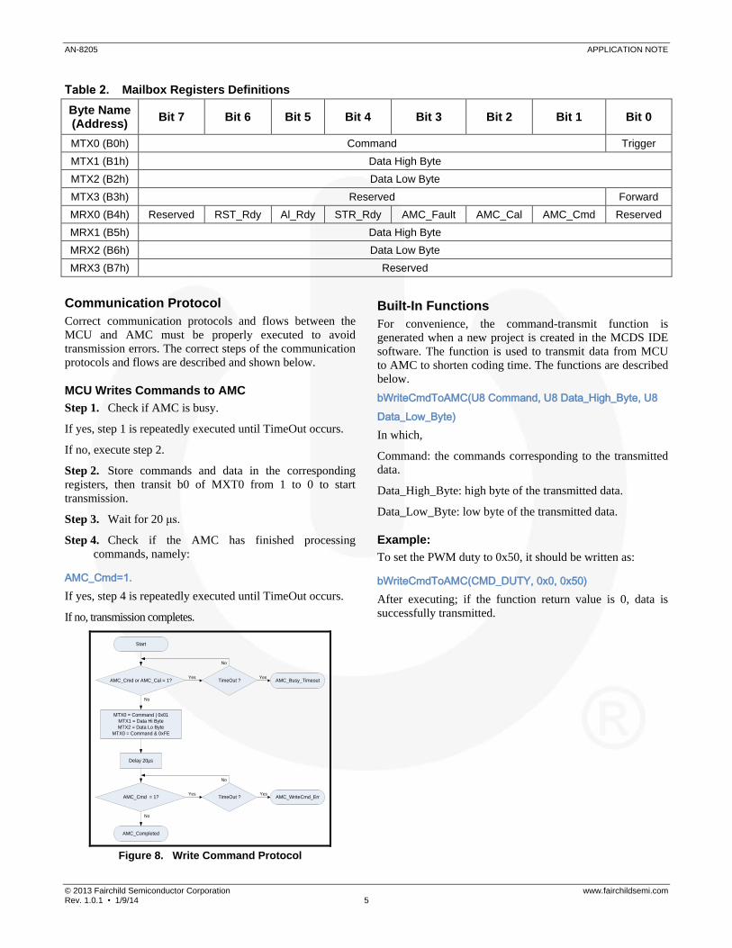
Table 2. Mailbox Registers Definitions
Byte Name (Address)
Bit 7 Bit 6 Bit 5 Bit 4 Bit 3 Bit 2 Bit 1 Bit 0
MTX0 (B0h) Command Trigger
MTX1 (B1h) Data High Byte
MTX2 (B2h) Data Low Byte
MTX3 (B3h) Reserved Forward
MRX0 (B4h) Reserved RST_Rdy Al_Rdy STR_Rdy AMC_Fault AMC_Cal AMC_Cmd Reserved
MRX1 (B5h) Data High Byte
MRX2 (B6h) Data Low Byte
MRX3 (B7h) Reserved
Communication Protocol
Correct communication protocols and flows between the
MCU and AMC must be properly executed to avoid
transmission errors. The correct steps of the communication
protocols and flows are described and shown below.
MCU Writes Commands to AMC
Step 1. Check if AMC is busy.
If yes, step 1 is repeatedly executed until TimeOut occurs.
If no, execute step 2.
Step 2. Store commands and data in the corresponding
registers, then transit b0 of MXT0 from 1 to 0 to start
transmission.
Step 3. Wait for 20 μs.
Step 4. Check if the AMC has finished processing
commands, namely:
AMC_Cmd=1.
If yes, step 4 is repeatedly executed until TimeOut occurs.
If no, transmission completes.
Start
AMC_Cmd or AMC_Cal = 1?
MTX0 = Command | 0x01
MTX1 = Data Hi Byte
MTX2 = Data Lo Byte
MTX0 = Command & 0xFE
Delay 20µs
AMC_Cmd = 1?
AMC_Completed
TimeOut ? AMC_Busy_Timeout
TimeOut ? AMC_WriteCmd_Err
Yes Yes
Yes Yes
No
No
No
No
Figure 8. Write Command Protocol
Built-In Functions
For convenience, the command-transmit function is
generated when a new project is created in the MCDS IDE
software. The function is used to transmit data from MCU
to AMC to shorten coding time. The functions are described
below.
bWriteCmdToAMC(U8 Command, U8 Data_High_Byte, U8
Data_Low_Byte)
In which,
Command: the commands corresponding to the transmitted
data.
Data_High_Byte: high byte of the transmitted data.
Data_Low_Byte: low byte of the transmitted data.
Example:
To set the PWM duty to 0x50, it should be written as:
bWriteCmdToAMC(CMD_DUTY, 0x0, 0x50)
After executing; if the function return value is 0, data is
successfully transmitted.

AN-8205 APPLICATION NOTE
© 2013 Fairchild Semiconductor Corporation www.fairchildsemi.com Rev. 1.0.1 • 1/9/14 6
Command Index
Command and associated parameters are shown in Table 3.
Table 3. Commands and Parameters
Command Index Parameter
CMD_RUN 0x10 1: RUN
0: FREE
CMD_DUTY 0x12 Duty (0~ 511)
CMD_ANGLE_SHIFT 0x14 Angle shift value (0~ 127)
CMD_HALL_PIN 0x80
Hall-Interface pin configuration:
0x40: HA/HB/HC= P14/P15/P16
0x80: HA/HB/HC= P24/P25/P26
Hall-Interface Files
After using MCDS IDE to generate a new project and generate code, the MCDS IDE automatically generates two files for
Hall interface. Table 4 shows file names and functions of those files.
Table 4. Hall-Interface Files
File Name Descriptions Editable
AMC_HallInterface.c
AMC_HallInterface.c provides common functions, such as WriteCmdToAMC(), ReadDataFromAMC(), Initial_AMCToSpeedIntegral(), and so on. Users cannot modify the file. Once the Generate Code function of the MCDS IDE is used, the file is overwritten.
No
AMC_HallInterface.h AMC_HallInterface.h provides definitions of all commands and definitions of the indexes when reading data. Users cannot modify the file. Once the Generate Code function of the MCDS IDE is used, the file is overwritten.
No
AMC_HallInterface.c
For convenience, AMC_HallInterface.c includes several common functions, described in Table 5.
Table 5. AMC_Hallsignal.c Common Functions
Function Name Descriptions
AMC_Reset( ) Resetting the AMC
btInitial_AMCToHallInterface()
Initial AMC and set AMC to Hall-Interface Mode Result: 0: Pass 1: AMC initial fail
bWriteCmdToAMC(Command, Data(H), Data(L) )
Transmitting data to the AMC.
Result: 00: Pass 02: Transmission error
Delay10 µs(value) Waiting for the AMC in 10 μs delay
Delay1 ms(value) Waiting for the AMC in 1 ms delay
The contents of AMC_HallInterface.c are listed as follows:
Line 13: Set Hall interface as Mode 0 (Default; HA= P14, HB= P15, HC= P16)
Line 18 ~ 22: Subroutine for reset AMC
Line 27 ~ 49: Subroutine for initial AMC and check the AMC status
AN-8205 APPLICATION NOTE
© 2013 Fairchild Semiconductor Corporation www.fairchildsemi.com Rev. 1.0.1 • 1/9/14 7
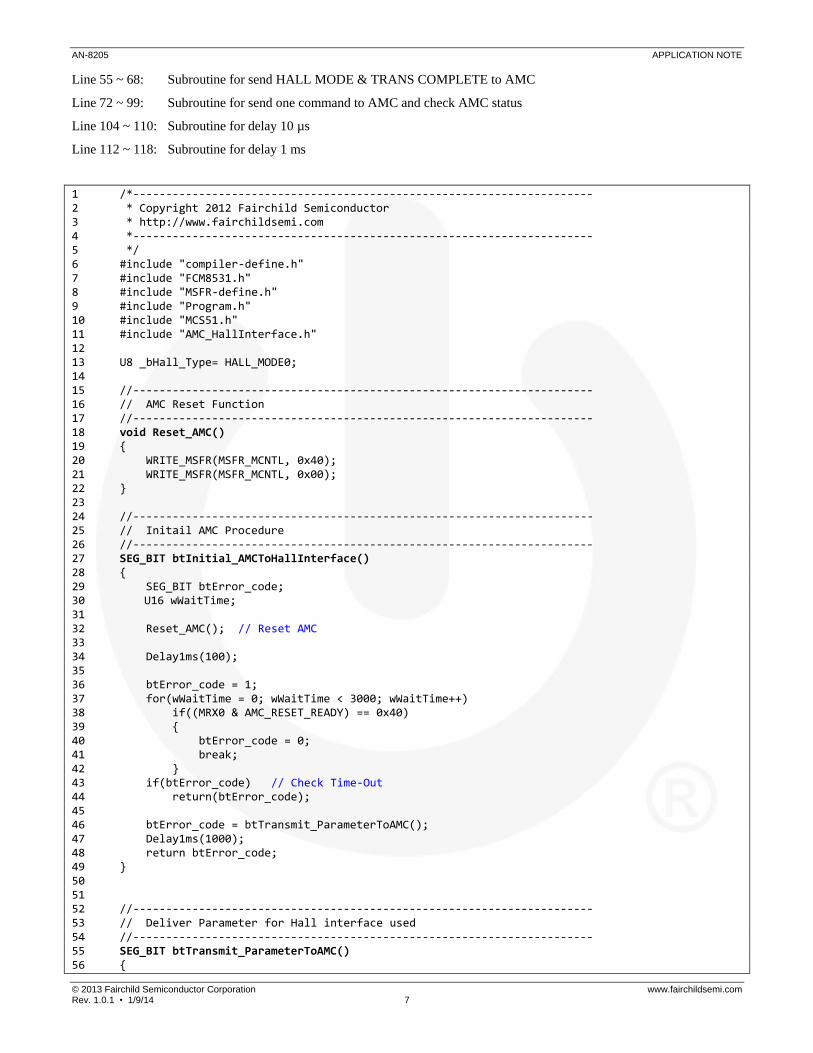
Line 55 ~ 68: Subroutine for send HALL MODE & TRANS COMPLETE to AMC
Line 72 ~ 99: Subroutine for send one command to AMC and check AMC status
Line 104 ~ 110: Subroutine for delay 10 µs
Line 112 ~ 118: Subroutine for delay 1 ms
1 /*---------------------------------------------------------------------- 2 * Copyright 2012 Fairchild Semiconductor 3 * http://www.fairchildsemi.com 4 *---------------------------------------------------------------------- 5 */ 6 #include "compiler-define.h" 7 #include "FCM8531.h" 8 #include "MSFR-define.h" 9 #include "Program.h" 10 #include "MCS51.h" 11 #include "AMC_HallInterface.h" 12 13 U8 _bHall_Type= HALL_MODE0; 14 15 //---------------------------------------------------------------------- 16 // AMC Reset Function 17 //---------------------------------------------------------------------- 18 void Reset_AMC() 19 { 20 WRITE_MSFR(MSFR_MCNTL, 0x40); 21 WRITE_MSFR(MSFR_MCNTL, 0x00); 22 } 23 24 //---------------------------------------------------------------------- 25 // Initail AMC Procedure 26 //---------------------------------------------------------------------- 27 SEG_BIT btInitial_AMCToHallInterface() 28 { 29 SEG_BIT btError_code; 30 U16 wWaitTime; 31 32 Reset_AMC(); // Reset AMC 33 34 Delay1ms(100); 35 36 btError_code = 1; 37 for(wWaitTime = 0; wWaitTime < 3000; wWaitTime++) 38 if((MRX0 & AMC_RESET_READY) == 0x40) 39 { 40 btError_code = 0; 41 break; 42 } 43 if(btError_code) // Check Time-Out 44 return(btError_code); 45 46 btError_code = btTransmit_ParameterToAMC(); 47 Delay1ms(1000); 48 return btError_code; 49 } 50 51 52 //---------------------------------------------------------------------- 53 // Deliver Parameter for Hall interface used 54 //---------------------------------------------------------------------- 55 SEG_BIT btTransmit_ParameterToAMC() 56 {

AN-8205 APPLICATION NOTE
© 2013 Fairchild Semiconductor Corporation www.fairchildsemi.com Rev. 1.0.1 • 1/9/14 8
57 U8 bWriteCMD_Status; 58 59 bWriteCMD_Status = bWriteCmdToAMC(CMD_HALL_PIN, 0, _bHall_Type); 60 if(bWriteCMD_Status) 61 return 1; 62 63 bWriteCMD_Status = bWriteCmdToAMC(CMD_TRANS_COMPLETE, 0, 0); 64 if(bWriteCMD_Status) 65 return 1; 66 67 return 0; 68 } 69 //---------------------------------------------------------------------- 70 // MPU write CMD to AMC 71 //---------------------------------------------------------------------- 72 U8 bWriteCmdToAMC(U8 bCommand, U8 bData_HB, U8 bData_LB) 73 { 74 U16 wWaitTime; 75 SEG_BIT btAMCStandby_Flag; 76 77 btAMCStandby_Flag = 0; 78 for(wWaitTime = 0; wWaitTime < 600; wWaitTime++) 79 if((MRX0 & (AMC_PROCESSING_CMD | AMC_CALCULATING)) == 0x0) 80 { 81 btAMCStandby_Flag = 1; 82 break; 83 } 84 if(!btAMCStandby_Flag) // Check Time-Out 85 return(AMC_BUSY_TIMEOUT); 86 87 MTX0 = bCommand | MCU_MAILBOX_INTR_STOP; 88 MTX1 = bData_HB; 89 MTX2 = bData_LB; 90 MTX0 = bCommand & MCU_MAILBOX_INTR_START; 91 92 Delay10us(2); 93 94 for(wWaitTime = 0; wWaitTime < 600; wWaitTime++) 95 if((MRX0 & AMC_PROCESSING_CMD) == 0) 96 return(AMC_COMPLETED); 97 98 return(AMC_WRITE_CMD_ERROR); 99 } 100 101 //---------------------------------------------------------------------- 102 // Delay time routine 103 //---------------------------------------------------------------------- 104 void Delay10us(U16 Counter) //Delay 10us 105 { 106 U16 i, k; 107 108 for(i = 0; i < Counter; i++) 109 for(k = 0; k < 16; k++); 110 } 111 112 void Delay1ms(U16 Counter) //Delay 1ms 113 { 114 U16 i; 115 116 for(i = 0; i < Counter; i++) 117 Delay10us(110); 118 }
AN-8205 APPLICATION NOTE
© 2013 Fairchild Semiconductor Corporation www.fairchildsemi.com Rev. 1.0.1 • 1/9/14 9
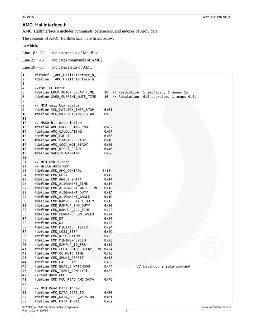
AMC_HallInterface.h
AMC_HallInterface.h includes commands, parameters, and indexes of AMC data.
The contents of AMC_HallInterface.h are listed below.
In which,
Line 18 ~ 22: indicates status of MailBox;
Line 22 ~ 46: indicates commands of AMC;
Line 59 ~ 68: indicates status of AMC;
1 #ifndef _AMC_HallInterface_h_ 2 #define _AMC_HallInterface_h_ 3 4 //for IEC-60730 5 #define LOCK_ROTOR_DELAY_TIME 10 // Resolution: 1 sec/step, 1 means 1s 6 #define OVER_CURRENT_MUTE_TIME 10 // Resolution: 0.5 sec/step, 1 means 0.5s 7 8 // MCU mail box status 9 #define MCU_MAILBOX_INTR_STOP 0x01 10 #define MCU_MAILBOX_INTR_START 0xFE 11 12 // MRX0 bit description 13 #define AMC_PROCESSING_CMD 0x02 14 #define AMC_CALCULATING 0x04 15 #define AMC_FAULT 0x08 16 #define AMC_STARTUP_READY 0x10 17 #define AMC_LOCK_MOT_READY 0x20 18 #define AMC_RESET_READY 0x40 19 #define SAFETY_WARNING 0x80 20 21 // MCU CMD list// 22 // Write data CMD 23 #define CMD_AMC_CONTROL 0x10 24 #define CMD_DUTY 0x12 25 #define CMD_ANGLE_SHIFT 0x14 26 #define CMD_ALIGNMENT_TIME 0x16 27 #define CMD_ALIGNMENT_WAIT_TIME 0x18 28 #define CMD_ALIGNMENT_DUTY 0x1A 29 #define CMD_ALIGNMENT_ANGLE 0x1C 30 #define CMD_RAMPUP_START_DUTY 0x1E 31 #define CMD_RAMPUP_END_DUTY 0x20 32 #define CMD_RAMPUP_ACC_TIME 0x22 33 #define CMD_FORWARD_RUN_SPEED 0x24 34 #define CMD_KP 0x26 35 #define CMD_KI 0x28 36 #define CMD_DIGITAL_FILTER 0x2A 37 #define CMD_LOSS_STEP 0x2C 38 #define CMD_RESOLUTION 0x2E 39 #define CMD_MINIMUM_SPEED 0x30 40 #define CMD_RAMPUP_ID_ERR 0x32 41 #define CMD_LOCK_ROTOR_DELAY_TIME 0x34 42 #define CMD_OC_MUTE_TIME 0x36 43 #define CMD_SHUNT_OFFSET 0x38 44 #define CMD_HALL_PIN 0x80 45 #define CMD_ENABLE_WATCHDOG 0xFA // Watchdog enable command 46 #define CMD_TRANS_COMPLETE 0xFE 47 //Read data CMD 48 #define CMD_MCU_READ_AMC_DATA 0xFC 49 50 // MCU Read Data Index 51 #define AMC_DATA_CORE_ID 0x00 52 #define AMC_DATA_CORE_VERSION 0x01 53 #define AMC_DATA_THETA 0x02

AN-8205 APPLICATION NOTE
© 2013 Fairchild Semiconductor Corporation www.fairchildsemi.com Rev. 1.0.1 • 1/9/14 10
54 #define AMC_DATA_KP 0x03 55 #define AMC_DATA_KI 0x04 56 #define AMC_DATA_ID_ERR 0x05 57 #define AMC_DATA_FW_SPEED 0x06 58 59 // AMC status code 60 #define AMC_COMPLETED 0x00 61 #define AMC_BUSY_TIMEOUT 0x01 62 #define AMC_WRITE_CMD_ERROR 0x02 63 #define AMC_RUNCMD_TIMEOUT 0x03 64 65 #define AMC_ERRCODE_PASS 0x80 66 #define AMC_ERRCODE_BUSY_TOUT 0x81 67 #define AMC_ERRCODE_CMD_ERROR 0x82 68 #define AMC_ERRCODE_RUNCMD_TOUT 0x83 69 70 // Motor Contril define 71 #define MOTOR_FREE 0x00 72 #define MOTOR_RUN 0x01 73 #define MOTOR_CW 0x02 74 #define USER_DEFINE_SVM_TABLE 0x20 75 76 #define CW 0x01 77 #define CCW 0x00 78 79 #define HALL_PINCFG1 0x80 // HA= P24, HB= P25, HC= P26 80 #define HALL_PINCFG0 0x40 // HA= P14, HB= P15, HC= P16 81 82 //---------------------------------------------------------------------- 83 // Export Function 84 //---------------------------------------------------------------------- 85 extern U8 _bHall_Type; 86 extern SEG_BIT btTransmit_ParameterToAMC(); 87 88 extern SEG_CODE U8 AS_Table[]; 89 90 extern SEG_BIT btInitial_AMCToHallInterface(); 91 extern U8 bWriteCmdToAMC(U8 bCommand, U8 bData_HB, U8 bData_LB); 92 extern void Delay10us(unsigned int Counter); 93 extern void Delay1ms(unsigned int Counter); 94 95 #endif

AN-8205 APPLICATION NOTE
© 2013 Fairchild Semiconductor Corporation www.fairchildsemi.com Rev. 1.0.1 • 1/9/14 11
Using Hall Interface
Using the Hall interface library to control the motor with
Hall sensor is explained in detail according to the attached
example program Sample_Hall_Interface in MCDS IDE.
Function
The main functions in the example program are:
Hall sensor input
Duty control by VR ( 0 ~ 4 V)
Sinusoidal wave current drive
FO (three pulses per revolution, see Figure 9)
Direction control
Current protection (cycle-by-cycle limit)
Short-circuit protection
HA
HB
HC
FO
Figure 9. FO Output
Table 6. Pin Assignments
Pin Type Function Description
P14 Input HA Input
Input range = 0~ 5 V P15 Input HB Input
P16 Input HC Input
P10 Output FO FO output, three pulses per revolution
P25 Input Direction Control 0: CW 1: CCW
P26 Output Status LED Off: System ready On: OCP protection Flash: AMC initial fail
ADC0 Input Speed Control Input Range = 0~4 V < 0.156 V: Motor stop > 0.156 V: Motor start
AOUT Output Angle Output 0~4 V

AN-8205 APPLICATION NOTE
© 2013 Fairchild Semiconductor Corporation www.fairchildsemi.com Rev. 1.0.1 • 1/9/14 12
Hardware Circuit
Besides the settings in the configuration section; the used I/O pins, timers, and interrupts in the example program also need to
be set. These are described below.
Figure 10. Circuit Diagram
IO Settings
Please refer to Figure 10 and Table 6. Because designed for
output signal, P10 is set as „Output direct drive‟ and the pin
name is FO. Because designed for direction control signal
input, P25 is set as „Open drain‟ and pin name is DIR.
Because designed for LED control signal output, P26 is set
as „Open drain‟ and pin name is nLED.
Figure 11. I/O Configuration Settings
Timer Settings
The TIMER0 is used in the example program to be a base of
acceleration/deceleration slope, which is set to 26.2 ms.
Figure 12. Timer0 Settings

AN-8205 APPLICATION NOTE
© 2013 Fairchild Semiconductor Corporation www.fairchildsemi.com Rev. 1.0.1 • 1/9/14 13
Interrupt Settings
The Hall Interrupt function in the example program is used
to generate the FO signal and the Hall Interrupt function
(INT10) has to be enabled and the trigger type is set to
Rise/Fall edge trigger.
Figure 13. Hall Configuration Settings
ADC Settings
The ADC0 (VSP) in the example program is used for speed
control input and the ADC interrupt (INT9) has to be
enabled and the sampling type is set to SAW top. After the
ADC conversion is completed, the ADC interrupt (INT9) is
generated to read the ADC0 (VSP) for controlling speed.
ADC Tigger
SAW
PWM
DUTY
Figure 14. ADC Configuration
Firmware Example
The initial subroutine of the main program is provided to set
initial values of PWM frequency, protection points, interrupt
parameters, and so on. Startup parameters of the AMC are
reset and communication between the AMC and MCU is
tested by the initial subroutine. The initial subroutine is only
executed in the beginning of the main program and then
infinite loops are executed.
The ADC samples each PWM cycle and generates interrupt
requests after conversion is completed. In the interrupt
service routine, the ADC0 value is stored to the
_wTarget_Duty. The main program judges whether the
_wTarget_Duty is greater than the
MOTOR_RAMPUP_DUTY. If greater, the PWM is
turned on to run the motor. The motor rotation direction is
determined according to the DIR switch setting and the
RUN bit of the MCNTL (MSFR 00h) is set. If
_wTarget_Duty is less than or equal to the
MOTOR_RAMPUP_DUTY; the MCTRL, duty, and AS
are cleared and the motor maintains Free state and the
ADC0 value is continually detected.
The timeout value set by the TIMER0 is about 26.2 ms.
When a time-out is generated in the main program, the
count value is added by one. If the count value is greater
than or equal to the SPEED_LOOP_RATE, the duty and
AS are updated.
The complete source codes are located on the IDE
installation disc under the following directory:
\Fairchildsemi\MCDS\Examples\keilC\Sample_Hall_Interface.
(for Keil C)
\Fairchildsemi\MCDS\Examples\SDCC\Sample_Hall_Interface.
(for SDCC)
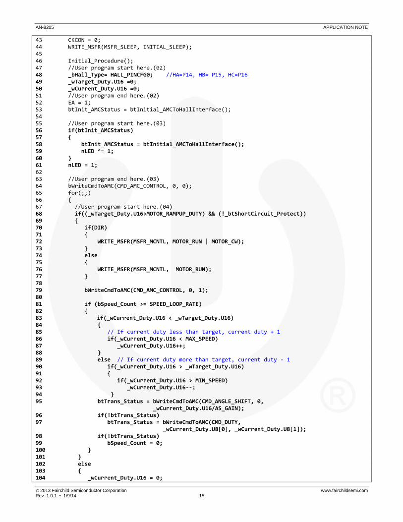
Main.c
Main.c is related to the system processing control. The
program explanation is listed below:
Line 4: set system clock as 30 MHz;
Line 7 ~12: define constants; in which:
MAX_SPEED: the maximum value of ADC0;
MIN_SPEED: the minimum value of ADC0;
SPEED_LOOP_RATE: the time of updating duty, unit
in 26.2 ms;
MOTOR_RAMPUP_DUTY: the motor starts to revolve
when VSP is greater than the value;
AS_GAIN: Angle shift value= duty/AS_GAIN +
AS_OFFSET (Sine-wave PWM only);
AS_OFFSET: Angle shift offset value;
Line 14 ~ 40: Define variables
Line 43 ~ 46: initialize the MCU;
Line 48 ~ 50: initialize variables;
AN-8205 APPLICATION NOTE
© 2013 Fairchild Semiconductor Corporation www.fairchildsemi.com Rev. 1.0.1 • 1/9/14 14
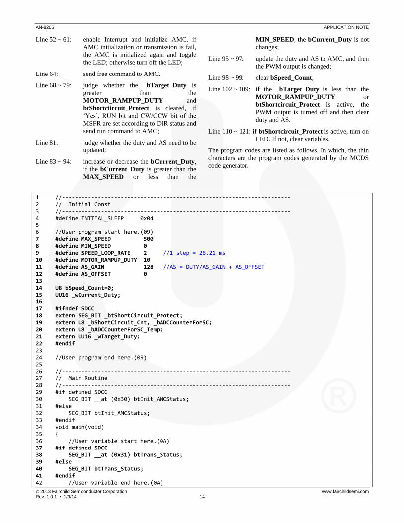
Line 52 ~ 61: enable Interrupt and initialize AMC. if
AMC initialization or transmission is fail,
the AMC is initialized again and toggle
the LED; otherwise turn off the LED;
Line 64: send free command to AMC.
Line 68 ~ 79: judge whether the _bTarget_Duty is
greater than the
MOTOR_RAMPUP_DUTY and
btShortciircuit_Protect is cleared, if
„Yes‟, RUN bit and CW/CCW bit of the
MSFR are set according to DIR status and
send run command to AMC;
Line 81: judge whether the duty and AS need to be
updated;
Line 83 ~ 94: increase or decrease the bCurrent_Duty,
if the bCurrent_Duty is greater than the
MAX_SPEED or less than the
MIN_SPEED, the bCurrent_Duty is not
changes;
Line 95 ~ 97: update the duty and AS to AMC, and then
the PWM output is changed;
Line 98 ~ 99: clear bSpeed_Count;
Line 102 ~ 109: if the _bTarget_Duty is less than the
MOTOR_RAMPUP_DUTY or
btShortcircuit_Protect is active, the
PWM output is turned off and then clear
duty and AS.
Line 110 ~ 121: if btShortcircuit_Protect is active, turn on
LED. If not, clear variables.
The program codes are listed as follows. In which, the thin
characters are the program codes generated by the MCDS
code generator.
1 //---------------------------------------------------------------------- 2 // Initial Const 3 //---------------------------------------------------------------------- 4 #define INITIAL_SLEEP 0x04 5 6 //User program start here.(09) 7 #define MAX_SPEED 500 8 #define MIN_SPEED 0 9 #define SPEED_LOOP_RATE 2 //1 step = 26.21 ms 10 #define MOTOR_RAMPUP_DUTY 10 11 #define AS_GAIN 128 //AS = DUTY/AS_GAIN + AS_OFFSET 12 #define AS_OFFSET 0 13 14 U8 bSpeed_Count=0; 15 UU16 _wCurrent_Duty; 16 17 #ifndef SDCC 18 extern SEG_BIT _btShortCircuit_Protect; 19 extern U8 _bShortCircuit_Cnt, _bADCCounterForSC; 20 extern U8 _bADCCounterForSC_Temp; 21 extern UU16 _wTarget_Duty; 22 #endif 23 24 //User program end here.(09) 25 26 //---------------------------------------------------------------------- 27 // Main Routine 28 //---------------------------------------------------------------------- 29 #if defined SDCC 30 SEG_BIT __at (0x30) btInit_AMCStatus; 31 #else 32 SEG_BIT btInit_AMCStatus; 33 #endif 34 void main(void) 35 { 36 //User variable start here.(0A) 37 #if defined SDCC 38 SEG_BIT __at (0x31) btTrans_Status; 39 #else 40 SEG_BIT btTrans_Status; 41 #endif 42 //User variable end here.(0A)
AN-8205 APPLICATION NOTE
© 2013 Fairchild Semiconductor Corporation www.fairchildsemi.com Rev. 1.0.1 • 1/9/14 15
43 CKCON = 0; 44 WRITE_MSFR(MSFR_SLEEP, INITIAL_SLEEP); 45 46 Initial_Procedure(); 47 //User program start here.(02) 48 _bHall_Type= HALL_PINCFG0; //HA=P14, HB= P15, HC=P16 49 _wTarget_Duty.U16 =0; 50 _wCurrent_Duty.U16 =0; 51 //User program end here.(02) 52 EA = 1; 53 btInit_AMCStatus = btInitial_AMCToHallInterface(); 54 55 //User program start here.(03) 56 if(btInit_AMCStatus) 57 { 58 btInit_AMCStatus = btInitial_AMCToHallInterface(); 59 nLED ^= 1; 60 } 61 nLED = 1; 62 63 //User program end here.(03) 64 bWriteCmdToAMC(CMD_AMC_CONTROL, 0, 0); 65 for(;;) 66 { 67 //User program start here.(04) 68 if((_wTarget_Duty.U16>MOTOR_RAMPUP_DUTY) && (!_btShortCircuit_Protect)) 69 { 70 if(DIR) 71 { 72 WRITE_MSFR(MSFR_MCNTL, MOTOR_RUN | MOTOR_CW); 73 } 74 else 75 { 76 WRITE_MSFR(MSFR_MCNTL, MOTOR_RUN); 77 } 78 79 bWriteCmdToAMC(CMD_AMC_CONTROL, 0, 1); 80 81 if (bSpeed_Count >= SPEED_LOOP_RATE) 82 { 83 if(_wCurrent_Duty.U16 < _wTarget_Duty.U16) 84 { 85 // If current duty less than target, current duty + 1 86 if(_wCurrent_Duty.U16 < MAX_SPEED) 87 _wCurrent_Duty.U16++; 88 } 89 else // If current duty more than target, current duty - 1 90 if(_wCurrent_Duty.U16 > _wTarget_Duty.U16) 91 { 92 if(_wCurrent_Duty.U16 > MIN_SPEED) 93 _wCurrent_Duty.U16--; 94 } 95 btTrans_Status = bWriteCmdToAMC(CMD_ANGLE_SHIFT, 0, _wCurrent_Duty.U16/AS_GAIN); 96 if(!btTrans_Status) 97 btTrans_Status = bWriteCmdToAMC(CMD_DUTY, _wCurrent_Duty.U8[0], _wCurrent_Duty.U8[1]); 98 if(!btTrans_Status) 99 bSpeed_Count = 0; 100 } 101 } 102 else 103 { 104 _wCurrent_Duty.U16 = 0;

AN-8205 APPLICATION NOTE
© 2013 Fairchild Semiconductor Corporation www.fairchildsemi.com Rev. 1.0.1 • 1/9/14 16
105 WRITE_MSFR(MSFR_MCNTL, MOTOR_FREE); 106 107 bWriteCmdToAMC(CMD_AMC_CONTROL, 0, 0); 108 btTrans_Status = bWriteCmdToAMC(CMD_ANGLE_SHIFT, 0, 0); 109 btTrans_Status = bWriteCmdToAMC(CMD_DUTY, 0, 0); 110 if(_btShortCircuit_Protect) 111 { 112 nLED = 0; //Fault LED on, release the flag after reset device 113 } 114 else //clear protect flag 115 { 116 _bADCCounterForSC = 0; 117 _bShortCircuit_Cnt = 0; 118 _bADCCounterForSC_Temp = 0; 119 _btShortCircuit_Protect = 0; 120 nLED = 1; //Fault LED off 121 } 122 } 123 //User program end here.(04) 124 }
MCS51.c
MCS51.c is related to initial I/O port setting for the MCU
and interrupt request processing. The program explanation
is listed below:
Line 6 ~ 23: interrupt service routine of TIMER0 timeout;
Line 19: increase bSpeed_Count.
The program codes are listed as follows. In which, the thin
characters are the program codes generated by the MCDS
code generator.
1 //---------------------------------------------------------------------- 2 // Interrupt Service Routine 3 //---------------------------------------------------------------------- 4 // Timer0 ISR 5 INTERRUPT(ISR_T0, VECTOR_ET0) 6 { 7 U8 bBackupADR; 8 UU16 V; 9 //User variable start here.(39) 10 11 //User variable end here.(39) 12 13 bBackupADR = MSFRADR; 14 //Initial Timer0 15 V.U16 = INITIAL_T0_INTERVAL; 16 TH0 = V.U8[MSB]; 17 TL0 = V.U8[LSB]; 18 //User program start here.(13) 19 bSpeed_Count++; 20 21 //User program end here.(13) 22 MSFRADR = bBackupADR; 23 }

AN-8205 APPLICATION NOTE
© 2013 Fairchild Semiconductor Corporation www.fairchildsemi.com Rev. 1.0.1 • 1/9/14 17
MotorCtrl.c
MotorCtrl.c is related to initial register setting for the MSFR
and interrupt request processing generated from motor
control. The program explanation is listed below:
Line 5 ~ 17: interrupt service routine of Hall signal
trigger;
Line 13: toggle the FO pin;
Line 20 ~ 48: interrupt service routine of ADC trigger;
Line 30 ~ 32: store ADC0 value (9-bit) into
_wTarget_Duty;
Line 34 ~ 35: output theta to AOUT pin;
Line 40 ~ 52: OCP analysis routine;
Line 58 ~ 87: Fault interrupt service routine;
The program codes are listed as follows. In which, the thin
characters are the program codes generated by the MCDS
code generator.
1 //---------------------------------------------------------------------- 2 // Interrupt Service Routine 3 //---------------------------------------------------------------------- 4 // Hall ISR 5 INTERRUPT(ISR_Hall, VECTOR_EX10) 6 { // Ex10 7 U8 bBackupADR; 8 //User variable start here.(22) 9 10 //User variable end here.(22) 11 bBackupADR = MSFRADR; 12 //User program start here.(16) 13 FO ^= 1; 14 15 //User program end here.(16) 16 MSFRADR = bBackupADR; 17 } 18 19 // ADC ISR 20 INTERRUPT(ISR_ADC, VECTOR_EX9) 21 { //EX9 22 U8 bBackupADR; 23 U8 bV; 24 //User variable start here.(23) 25 U8 bAngle; 26 27 //User variable end here.(23) 28 bBackupADR = MSFRADR; 29 //User program start here.(1A) 30 READ_MSFR(MSFR_ADC0H, _wTarget_Duty.U8[0]); 31 READ_MSFR(MSFR_ADC0L, _wTarget_Duty.U8[1]); 32 _wTarget_Duty.U16 >>= 7; 33 _bADCCounterForSC++; 34 READ_MSFR(MSFR_ECL, bAngle); 35 WRITE_MSFR(MSFR_DAC3, bAngle); 36 37 //User program end here.(1A) 38 39 READ_MSFR(MSFR_OCSTA, bV); 40 if (bV) 41 { 42 if (bV & 0x08) // OCAH 43 Evt_OCHA(); 44 if (bV & 0x10) // OCBH 45 Evt_OCHB(); 46 if (bV & 0x20) // OCCH 47 Evt_OCHC(); 48 } 49 50 //User program start here.(17)

AN-8205 APPLICATION NOTE
© 2013 Fairchild Semiconductor Corporation www.fairchildsemi.com Rev. 1.0.1 • 1/9/14 18
51 else 52 nLED = 1; 53 54 //User program end here.(17) 55 MSFRADR = bBackupADR; 56 } 57 58 // Fault ISR 59 INTERRUPT(ISR_Fault, VECTOR_EX8) 60 { //Ex8 61 U8 bBackupADR; 62 U8 bV; 63 //User variable start here.(24) 64 65 //User variable end here.(24) 66 67 bBackupADR = MSFRADR; 68 READ_MSFR(MSFR_MSTAT, bV); 69 if (bV & 0x7F) 70 { 71 //User program start here.(1B) 72 73 //User program end here.(1B) 74 if (bV & 0x20) // Short A 75 Evt_ShortA(); 76 if (bV & 0x10) // Short B 77 Evt_ShortB(); 78 if (bV & 0x08) // Short C 79 Evt_ShortC(); 80 if (bV & 0x04) // Hall Error 81 Evt_HERR(); 82 //User program start here.(18) 83 84 //User program end here.(18) 85 } 86 MSFRADR = bBackupADR; 87 }
Related Resources
FCM8531 − MCU Embedded and Configurable 3-Phase PMSM / BLDC Motor Controller
AN-8202 − FCM8531 User Manual - Hardware Description
AN-8207 − User Guide for MCDS IDE of FCM8531
DISCLAIMER FAIRCHILD SEMICONDUCTOR RESERVES THE RIGHT TO MAKE CHANGES WITHOUT FURTHER NOTICE TO ANY PRODUCTS HEREIN TO IMPROVE RELIABILITY, FUNCTION, OR DESIGN. FAIRCHILD DOES NOT ASSUME ANY LIABILITY ARISING OUT OF THE APPLICATION OR USE OF ANY PRODUCT OR CIRCUIT DESCRIBED HEREIN; NEITHER DOES IT CONVEY ANY LICENSE UNDER ITS PATENT RIGHTS, NOR THE RIGHTS OF OTHERS. LIFE SUPPORT POLICY FAIRCHILD’S PRODUCTS ARE NOT AUTHORIZED FOR USE AS CRITICAL COMPONENTS IN LIFE SUPPORT DEVICES OR SYSTEMS WITHOUT THE EXPRESS WRITTEN APPROVAL OF THE PRESIDENT OF FAIRCHILD SEMICONDUCTOR CORPORATION. As used herein: 1. Life support devices or systems are devices or systems
which, (a) are intended for surgical implant into the body, or (b) support or sustain life, or (c) whose failure to perform when properly used in accordance with instructions for use provided in the labeling, can be reasonably expected to result in significant injury to the user.
2. A critical component is any component of a life support device or system whose failure to perform can be reasonably expected to cause the failure of the life support device or system, or to affect its safety or effectiveness.