
AN-70 STOL AIRCRAFT CHARACTERISTICS AT HIGH ANGLES OF ...
6
ICAS 2002 CONGRESS 1 AN-70 STOL AIRCRAFT CHARACTERISTICS AT HIGH ANGLES OF ATTACK AND TAKEOFF AND LANDING CHARACTERISTICS Piotr Balabuyev, Oleg Bogdanov, Vladimir Kudryavtsev, Valentin Pustovoytov ANTONOV Aeronautical Scientific/Technical Complex When developing the An-70 aerodynamic configuration (Fig. 1), the objective was to achieve high cruise lift-to-drag ratio and high maximum lift coefficient values for the short takeoff and landing conditions combined with favourable stalling performance of the aircraft. Fig. 1. Three view scheme of An-70 The extensive research work has been performed by ANTONOV ASTC, TsAGI (Central Institute for Aero and Hydrodynamics Research) and many other industry institutes and enterprises codesigners. The design tests of 385 aerodynamic configurations of the aircraft in 55 configurations have been performed, 22 aircraft models with 10 wings and 4 flaps types have been tested. A total volume of the experimental tests in the wind tunnels made more than 1400 hours; in this case most of this volume were the tests with the turboprop engines simulators. As a result of the theoretical and experimental research, special thickened moderately supercritical airfoil sections were developed for the An-70 wing in cooperation with the Central Institute for Aero and Hydrodynamics Research (TsAGI) of the Russian Federation. These airfoils feature high lift-to-drag ratio at the required cruising Mach numbers (M cruise ≈ 0.7) and high lifting properties at low flight speeds making it possible to design a comparatively thick wing (C max mean = 0.14) with modest wing sweepback (χ w = 14°), sufficiently high aspect ratio (λ w = 9.5), and low structural weight. In order to assure the aircraft tendency to nose down in cruising configuration with engines operating at low power settings, a specific geometric wing twist was found featuring comparatively low twist angles up to mid-span and several times higher twist angles over the outer wing section. It was expected that earlier flow separation in the wing root would persist at high engine power settings as this portion of the An-70 wing is not blown by the propfan jets. Flow separation at the wing root portion reduces the growth of wash in the area of horizontal tail as the angle of attack decreases resulting in the growth of the aircraft nose-down pitching moment. The elevator in this case retains its effectiveness since, with the conventional arrangement of the horizontal tail, the separated flow slipstream at high angles of attack passes considerably above the horizontal tail. In order to achieve high maximum lift coefficient values for short takeoff and landing conditions, the An-70 has been equipped with a double-slotted double-hinged flap with conical extension (Fig. 2). The flap segments deflection angles and slot parameters for the flap were selected as a result of testing the aircraft model with propfan engine simulators running in the TsAGI large T-101 wind tunnel.
Transcript of AN-70 STOL AIRCRAFT CHARACTERISTICS AT HIGH ANGLES OF ...
ICAS 2002 CONGRESS
1
AN-70 STOL AIRCRAFT CHARACTERISTICS AT HIGH ANGLES OF ATTACK AND TAKEOFF AND LANDING CHARACTERISTICS
Piotr Balabuyev, Oleg Bogdanov, Vladimir Kudryavtsev, Valentin Pustovoytov
ANTONOV Aeronautical Scientific/Technical Complex
When developing the An-70 aerodynamic
configuration (Fig. 1), the objective was to achieve high cruise lift-to-drag ratio and high maximum lift coefficient values for the short takeoff and landing conditions combined with favourable stalling performance of the aircraft.
Fig. 1. Three view scheme of An-70
The extensive research work has been
performed by ANTONOV ASTC, TsAGI (Central Institute for Aero and Hydrodynamics Research) and many other industry institutes and enterprises codesigners. The design tests of 385 aerodynamic configurations of the aircraft in 55 configurations have been performed, 22 aircraft models with 10 wings and 4 flaps types have been tested. A total volume of the experimental tests in the wind tunnels made more than 1400 hours; in this case
most of this volume were the tests with the turboprop engines simulators.
As a result of the theoretical and experimental research, special thickened moderately supercritical airfoil sections were developed for the An-70 wing in cooperation with the Central Institute for Aero and Hydrodynamics Research (TsAGI) of the Russian Federation. These airfoils feature high lift-to-drag ratio at the required cruising Mach numbers (Mcruise ≈ 0.7) and high lifting properties at low flight speeds making it possible to design a comparatively thick wing (Cmaxmean= 0.14) with modest wing sweepback (χw = 14°), sufficiently high aspect ratio (λw = 9.5), and low structural weight.
In order to assure the aircraft tendency to nose down in cruising configuration with engines operating at low power settings, a specific geometric wing twist was found featuring comparatively low twist angles up to mid-span and several times higher twist angles over the outer wing section. It was expected that earlier flow separation in the wing root would persist at high engine power settings as this portion of the An-70 wing is not blown by the propfan jets. Flow separation at the wing root portion reduces the growth of wash in the area of horizontal tail as the angle of attack decreases resulting in the growth of the aircraft nose-down pitching moment. The elevator in this case retains its effectiveness since, with the conventional arrangement of the horizontal tail, the separated flow slipstream at high angles of attack passes considerably above the horizontal tail.
In order to achieve high maximum lift coefficient values for short takeoff and landing conditions, the An-70 has been equipped with a double-slotted double-hinged flap with conical extension (Fig. 2). The flap segments deflection angles and slot parameters for the flap were selected as a result of testing the aircraft model with propfan engine simulators running in the TsAGI large T-101 wind tunnel.

Piotr Balabuyev, Oleg Bogdanov, Vladimir Kudryavtsev, Valentin Pustovoytov
2
To amplify the aircraft’s tendency to nose down, different types of the wing leading edge high-lift devices were used: a slotted extensible slat was used over the wing span between the inboard engine nacelle and the wing tip, and a wing leading edge flap – over the wing span between the fuselage side and the inboard engine nacelle.
Such wing high-lift devices, with due account for their surface blowing by the high-load counterrotating propfan jets, afforded ground to believe that the required maximum lift coefficient
CL values would be achieved. In order to reach the target takeoff speeds (VLOF = 195…230 km/h), the required maximum lift coefficient CL is 3.54…3.64 with three engines operating at takeoff power. In order to reach the target landing speeds (VAPP = 165…195 km/h), the required maximum lift coefficient CL is 4.35…4.5 with three engines operating at the power setting required to descend into a short strip following the prescribed glide slope (θGS = –3.5…–5°). Such CL maximum lift coefficient values were obtained at takeoff and landing with the respective deflection angles of the first and second flap segments. The deflection angles of the slotted extensible slats and wing leading edge flaps proved acceptable both for the takeoff and the landing conditions with the stall-
free flow about wing persisting up to the same angles as without the surface blowing.
The peculiarities of aerodynamic configuration described above allowed to forecast good aircraft stalling performance. However, the problem of the aircraft protection against stall, especially at STOL conditions, was not resolved in full. This is due, primarily, to the fact that the propfans operation considerably reduces the aircraft’s inherent static longitudinal stability and, secondly, because the double-hinged elevator selected so as to provide the aircraft trim at all flight conditions and to enable the air dropping of heavy cargoes has high effectiveness (the An-70 has a fixed horizontal tail). Combination of these factors results in a very small inclination of the trim curves of the elevator deflection angle against the angle of attack at STOL conditions with aft CG positions. Calculations demonstrate that it is practically impossible to ensure the required level of back pressure forces when the aircraft reaches the angles of attack corresponding to activation of the stall warning by the automation of the primary control system based exclusively on the proportional control laws. Therefore, a decision was made to use a ОПР-α angle of attack limiter (stall warning and barrier system) with the operating algorithm based on the use of both the proportional and integral control laws. This algorithm is described by the following equation:
,]}вК)(вК[)V(К)(К
)V(Кp1]К)(КК
)(К)V(К{)р(WК)р(W
876
1031
8796
1РAРПОПР
задпрвзв
прввзадвв
звпрвв
[
α⋅+α−α×⋅⋅δ×
×+α⋅+α−α⋅⋅×
×δ⋅⋅⋅=δ
σσ
σ
α−∆
&
&
where )р(WРП – is the gear function of the elevator
servo; К – is a fixed coefficient characterising the
relation between the elevator deflection angle and the travel of actuator output member in the elevator channel;
)р(WРA – is the gear function of the elevator actuator;
)V(К прв , )V(К прв10– are the coefficients which
are functions of the indicated airspeed; )(К зв1
δ – is the coefficient which is a function of the flap deflection angle;
7вК ,
8вК ,
9вК – are fixed coefficients;
Fig. 2. High lift devices of An-70

AN-70 STOL AIRCRAFT CHARACTERISTICS AT HIGH ANGLES OF ATTACK AND TAKEOFF AND LANDING CHARACTERISTICS
3
3σ - is the integral feedback connection/ disconnection signal ( 3σ = 1: integral feedback is on in response to SHOCK STRUT NOT COMPRESSED signal, 3σ = 0: integral feedback is off in response to SHOCK STRUT COMPRESSED signal;
6σ – is the ОПР-α system operation signal ( 6σ = 1: the ОПР-α system is operating, 6σ = 0: the ОПР-α system is not operating).
The ОПР-α system activation condition
( 6σ = 1): α−δδα≥α &5,0)М,,з( прзад .
The ОПР-α system deactivation condition
( 6σ = 0): α−δδα<α &5,0)М,,( прззад .
Here, the )М,,( прззад δδα – is the preset angle of attack which is a function of Mach number (cruising configuration of the aircraft) and of the flaps and slats deflection angles (takeoff and landing configurations). The preset angle of attack value was selected in the course of the An-70 flight simulator investigations so that with the control wheel pulled full back the angle of attack stall margin was at least 1…2°.
The An-70 was flight tested at high angles of attack in two stages.
At the first stage, the flight tests were aimed at determining the maximum lift coefficient values, studying the aircraft behaviour in the course of stall, and obtaining information for modifying, if necessary, the ОПР-α adjustment. At this stage, the stall warning and barrier system was disengaged. Moreover, all feedback in the stability and control augmentation systems of the aircraft was disengaged (with only a pitch damper remaining on, which the pilot could disengage in flight). Thus, feedforward was ensured between the displacements of control levers and airplane control surfaces at all flight conditions including the spin condition. Testing in the T-105 vertical-flow wind tunnel of TsAGI demonstrated that the An-70 dynamically similar free-spinning model recovered from spin with a delay of 0.5…1 turn maximum with the conventional spin recovery procedure used.
At the second stage, certification flight tests were carried out in order to determine whether the aircraft is adequately protected against stalling and to establish compliance of the aircraft performance characteristics with the requirements of the AP-25 (FAR-25) regulations and the Air Force Special
Technical Requirements. At this stage, the aircraft’s ЭДСУ-70 fly-by-wire control system functioned in the standard operating mode.
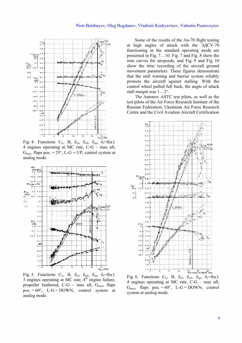
Fig. 3 shows the aircraft parameters as a function of the angle of attack obtained in straight line decelerations down to stall in the takeoff configuration with three engines operating at maximum continuous power setting (the fourth engine shut down, its propfan feathered). The maximum lift coefficient value achieved in these conditions was 3.8. Fig. 4 shows similar aircraft parameters with four engines operating at maximum continuous power setting. The CL maximum lift coefficient value achieved in these conditions was 4.8. Fig. 5 shows the aircraft parameters as a function of the angle of attack obtained in straight line decelerations down to stall in the landing configuration with three engines operating at minimum power setting. (The minimum power was set somewhat lower than required to follow the landing glide slope and the setting was limited with a stop). The maximum lift coefficient value achieved in these conditions was 4.34 which corresponded to the analysis. Fig. 6 shows the aircraft parameters in the same configuration but with four engines operating at the maximum continuous rating. The maximum lift coefficient value achieved in these conditions was about 7.
Fig. 3. Functions CL, B, δel, δail, δsp, δr=f(α):3 engines operating at MC rate, 4th engine failure,propeller feathered, C-G – max aft, Gmax, flapspos. = 25°, L-G = UP, control system at analogmode.
Piotr Balabuyev, Oleg Bogdanov, Vladimir Kudryavtsev, Valentin Pustovoytov
4
Fig. 4. Functions CL, B, δel, δail, δsp, δr=f(α): 4 engines operating at MC rate, C-G – max aft, Gmax, flaps pos. = 25°, L-G = UP, control system at analog mode.
Fig. 5. Functions CL, B, δel, δail, δsp, δr=f(α): 3 engines operating at MC rate, 4th engine failure, propeller feathered, C-G – max aft, Gmax, flaps pos. = 60°, L-G = DOWN, control system at analog mode.
Some of the results of the An-70 flight testing at high angles of attack with the ЭДСУ-70 functioning in the standard operating mode are presented in Fig. 7…10. Fig. 7 and Fig. 8 show the trim curves for airspeeds, and Fig. 9 and Fig. 10 show the time recording of the aircraft ground movement parameters. These figures demonstrate that the stall warning and barrier system reliably protects the aircraft against stalling. With the control wheel pulled full back, the angle of attack stall margin was 1…2°.
The Antonov ASTC test pilots, as well as the test pilots of the Air Force Research Institute of the Russian Federation, Ukrainian Air Force Research Centre and the Civil Aviation Aircraft Certification
Fig. 6. Functions CL, B, δel, δail, δsp, δr=f(α): 4 engines operating at MC rate, C-G – max aft, Gmax, flaps pos. = 60°, L-G = DOWN, control system at analog mode.

AN-70 STOL AIRCRAFT CHARACTERISTICS AT HIGH ANGLES OF ATTACK AND TAKEOFF AND LANDING CHARACTERISTICS
5
Centre of the Russian Federation expressed high opinions of the An-70’s STOL performances at high angles of attack. In all deceleration starting from the trimming speed down to the stalling speed, under all tested engine power settings, the aircraft was capable of nose down trim to ensure rapid acceleration. Up to the stalling moment, a possibility is provided for establishing and eliminating roll and yaw by direct actions of control levers without pitching-up.
Fig. 7. Functions δel, Xel, Pel, α, αallowed = f(Vcal): 4 engines operating at MC rate, C-G – max aft, Gmax, flaps pos. = 25°, L-G = UP, control system at digital mode.
During straight line decelerations, decelerations in turns, and elevator advances, the stall indications include setting the control column back as far as it will go, dropping the nose down with a possible slight bank, stepwise dropping of the current vertical acceleration by 0.2 units.
Fig. 8. Functions δel, Xel, Pel, α, αallowed = f(Vcal): 4 engines operating at MC rate, C-G – max aft, Gmax, flaps pos. = 60°, L-G = DOWN, control system at digital mode.
Fig. 9. Parameters versus time at wing level deceleration flight 4 engines operating at MC rate,C-G – max aft, Gmean, flaps pos. = 25°, slat pos . = 20°, L-G = UP, control system at digital mode.

Piotr Balabuyev, Oleg Bogdanov, Vladimir Kudryavtsev, Valentin Pustovoytov
6
Fig. 10. Parameters versus time at wing level deceleration flight: 4 engines operating at MC rate, C-G –
max aft, Gmean, flaps pos. = 60°, slat pos. = 20°, L-G = DOWN, control system at digital mode.
The aircraft recovery from stall is easy and accomplished using the standard procedure. Loss of altitude during recovery from stall and levelling the aircraft off does not exceed 500 m. The angle of bank appearing from the stalling moment till complete recovery from stall does not exceed 20°. At the maximum angles of attack achieved, which exceeded stalling angles by 5…10°, no abnormalities were detected in the aircraft behaviour, the margin of longitudinal control allows to bring the angle of attack down to the operational value. The aircraft approach to the stalling conditions is accompanied by the characteristic aerodynamic buffeting of various levels of intensity depending on configuration and the engine power setting which, however, cannot serve as a natural early warning indication. The artificial warning indications made available in the aircraft – aural, light and tactile – provide unambiguous readily perceptible warning about the approach of stall with a sufficient margin to prevent unexpected stall. The ОПР-α stall warning and barrier system demonstrated stable operation in all flight conditions providing reliable protection
of the aircraft against reaching the stalling angles. The ОПР-α can be regarded as a manoeuvrability augmentation system as it enables manoeuvring up to the allowable angles of attack without significantly stressing the crew attention.
The achieved high-lifting properties of the wing of the AN-70 aircraft have permitted to obtain the small takeoff/landing speeds that in combination with a high thrust-to-weight ratio of the aircraft at takeoff and utilization of the high-power braking (wheels brake, propellers reverse thrust, spoilers deflection - ground spoilers) on the pre-spinning signal of the landing gear during touchdown provided the unique aircraft performance that allow to perform takeoff and landing from the field of 600-700 m long.
At present the AN-70 aicraft flight test programmes on determination its characteristics at high angles of attack and takeoff/landing performance have been comleted. They testified that according to these performance the AN-70 aircraft overpasses the C-17 operating aircraft (USA) and A-400M future transport aircraft (West Europe).