Amwaj Islands Constucted with Geotubes - Geotec Islands Constucte… · · 2005-04-112 Figure 1....
14
1 AMWAJ ISLANDS CONSTRUCTED WITH GEOTUBES, BAHRAIN Jack Fowler, Ph.D., PE 1 , Thomas C. Stephens 2 , Mario Santiago 3 , and Pieter de Bruin 4 ABSTRACT The Amwaj Islands Project, Venice style resort involves the development of a new island off the northeast shore of Muharraq Island in Bahrain. The key element in the successful design, construction and completion of the Amwaj Island development project was the use of sand filled Geotubes to form the island perimeter for containment of 12 million cubic meter of dredged sand that formed the basic platform for the development project. The island perimeter was constructed by hydraulically filling Geotubes with local sands from proposed navigation channels and marinas serving residents and businesses on the main island of Bahrain. The development is strategically located on the northeastern end of Muharraq-Bahrain between the Persian Gulf and Bahrain Sea. Amwaj Island development will provide a variety of amenities such as living in beach front properties, hotels, restaurants, recreation parks, theaters, marinas, and golf courses. The island will also provide a neighborhood mall and entertainment center and will not only cater to the young but will also accommodate the elderly as a retirement destination. The Ossis Property Developers (Ossis) is responsible for land reclamation of 2.79 million square meters of open sea in a shallow reef area to form land at the north east of Muharraq Island, Bahrain. Engineers from Ossis, TC Nicolon Corporation in the US and The Netherlands were responsible for the planning and design of the sand filled Geotube containment structures for the island perimeter and shoreline and foreshore protection systems. Submerged Geotubes are also to be filled with sand along the islands’ northwest, northern, and northeast perimeter and to be protected with rip rap stone to serve as offshore segmented breakwater structures. Approximately 10 kilometers of 2.0 to 2.6 meter high Geotubes are being used to successfully construct this project. Infrastructure developments included access roads, bridges, marinas, communication systems, electrical power network, water supply, and sewage collection and treatment systems. The project cost for development of the entire land area for phase one was $70 million for land cost, $80 million for land development, and $8.2 million for contingencies for a total cost of $158 million ($57 per square meter). The net land area useable for development after accounting for lagoons, wastage and service requirements was only 50 percent. Keywords: Dredged Material, Island Perimeter, Containment Island, Disposal Area, Geotubes, Geotube Breakwater Structures INTRODUCTION One of the first Geotube applications in Bahrain was for the construction of a dredged material containment island designated as Amwaj (Arabic for waves). The site (Figure 1) is strategically located 1.6 kilometers off shore at the northeastern end of Muharraq-Bahrain. This location along the islands is boasted to be the purest and clearest of waters along the Bahrain coastline. The development consists of dredging cohesion-less ocean sediments reclaimed from proposed navigation channels and marinas. The reclamation project will provide new land for associated civil engineering infrastructures for the construction of five and four star hotels and restaurants, golf course, homes, condominiums and many amenities. The island perimeter consists of various 1 Geotec Associates, 5000 Lowery Rd, Vicksburg, MS 39180, 601-636-5475, Geotechnical Consultant 2 TC Mirafi Corporation, Commerce, GA 3 Ossis Property Developers, Bahrain 4 TC Mirafi BV, Almelo, The Netherlands
Transcript of Amwaj Islands Constucted with Geotubes - Geotec Islands Constucte… · · 2005-04-112 Figure 1....

1
AMWAJ ISLANDS CONSTRUCTED WITH GEOTUBES, BAHRAIN
Jack Fowler, Ph.D., PE1, Thomas C. Stephens2, Mario Santiago3, and Pieter de Bruin4
ABSTRACT
The Amwaj Islands Project, Venice style resort involves the development of a new island off the northeast shore of Muharraq Island in Bahrain. The key element in the successful design, construction and completion of the Amwaj Island development project was the use of sand filled Geotubes to form the island perimeter for containment of 12 million cubic meter of dredged sand that formed the basic platform for the development project. The island perimeter was constructed by hydraulically filling Geotubes with local sands from proposed navigation channels and marinas serving residents and businesses on the main island of Bahrain. The development is strategically located on the northeastern end of Muharraq-Bahrain between the Persian Gulf and Bahrain Sea. Amwaj Island development will provide a variety of amenities such as living in beach front properties, hotels, restaurants, recreation parks, theaters, marinas, and golf courses. The island will also provide a neighborhood mall and entertainment center and will not only cater to the young but will also accommodate the elderly as a retirement destination. The Ossis Property Developers (Ossis) is responsible for land reclamation of 2.79 million square meters of open sea in a shallow reef area to form land at the north east of Muharraq Island, Bahrain. Engineers from Ossis, TC Nicolon Corporation in the US and The Netherlands were responsible for the planning and design of the sand filled Geotube containment structures for the island perimeter and shoreline and foreshore protection systems. Submerged Geotubes are also to be filled with sand along the islands’ northwest, northern, and northeast perimeter and to be protected with rip rap stone to serve as offshore segmented breakwater structures. Approximately 10 kilometers of 2.0 to 2.6 meter high Geotubes are being used to successfully construct this project. Infrastructure developments included access roads, bridges, marinas, communication systems, electrical power network, water supply, and sewage collection and treatment systems. The project cost for development of the entire land area for phase one was $70 million for land cost, $80 million for land development, and $8.2 million for contingencies for a total cost of $158 million ($57 per square meter). The net land area useable for development after accounting for lagoons, wastage and service requirements was only 50 percent. Keywords: Dredged Material, Island Perimeter, Containment Island, Disposal Area, Geotubes, Geotube Breakwater Structures
INTRODUCTION One of the first Geotube applications in Bahrain was for the construction of a dredged material containment island designated as Amwaj (Arabic for waves). The site (Figure 1) is strategically located 1.6 kilometers off shore at the northeastern end of Muharraq-Bahrain. This location along the islands is boasted to be the purest and clearest of waters along the Bahrain coastline. The development consists of dredging cohesion-less ocean sediments reclaimed from proposed navigation channels and marinas. The reclamation project will provide new land for associated civil engineering infrastructures for the construction of five and four star hotels and restaurants, golf course, homes, condominiums and many amenities. The island perimeter consists of various
1 Geotec Associates, 5000 Lowery Rd, Vicksburg, MS 39180, 601-636-5475, Geotechnical Consultant 2 TC Mirafi Corporation, Commerce, GA 3 Ossis Property Developers, Bahrain
4 TC Mirafi BV, Almelo, The Netherlands

2
Figure 1. Vicinity Map of Bahrain Island size Geotubes that were filled with ocean sand and positioned end to end to construct the containment area. Geotubes were also stacked to achieve the necessary elevation required for protection from oceans tidal fluctuations of 1.5 meters and anticipated storm surges of 3.0 meters. Palm trees and various other plants and vegetation will be planted on the island.
BAHRAIN Bahrain is located in the Middle East, an archipelago in the Persian Gulf, east of Saudi Arabia. Bahrain Island land area consists of 620 square kilometer or about 3.5 times the size of Washington DC. Its 161 kilometer coastline has no contiguous land boundaries but claims 24 nautical mile contiguous zone and 12 nautical mile territorial sea. Climate is arid and mild with pleasant winters and very hot humid summers. The terrain is mostly low desert plains rising gently to low central escarpment. Its natural resources are oil and associated and non-associated natural gas and fish. The Bahraini population consist of about 600,000 of which 63% Bahraini, 13% Asian, 10% Arabic, 6% other and 8% Iranian. The labor forces consist of 140,000 with 42% Bahraini.
3
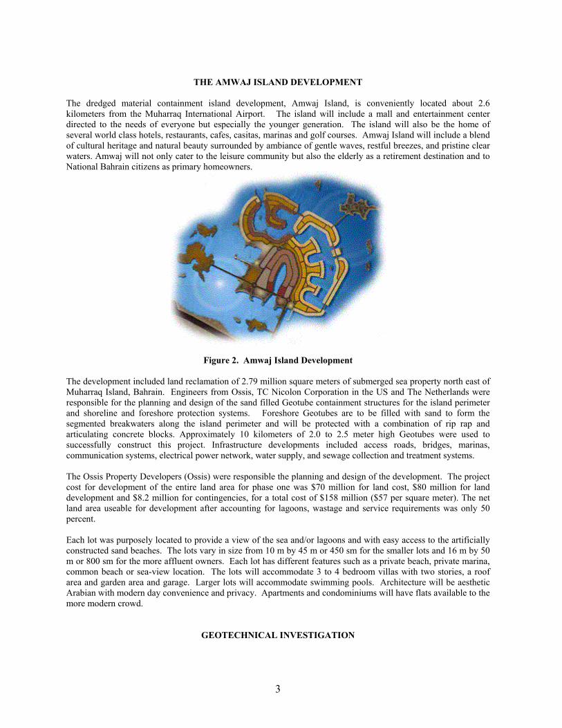
THE AMWAJ ISLAND DEVELOPMENT
The dredged material containment island development, Amwaj Island, is conveniently located about 2.6 kilometers from the Muharraq International Airport. The island will include a mall and entertainment center directed to the needs of everyone but especially the younger generation. The island will also be the home of several world class hotels, restaurants, cafes, casitas, marinas and golf courses. Amwaj Island will include a blend of cultural heritage and natural beauty surrounded by ambiance of gentle waves, restful breezes, and pristine clear waters. Amwaj will not only cater to the leisure community but also the elderly as a retirement destination and to National Bahrain citizens as primary homeowners.
Figure 2. Amwaj Island Development The development included land reclamation of 2.79 million square meters of submerged sea property north east of Muharraq Island, Bahrain. Engineers from Ossis, TC Nicolon Corporation in the US and The Netherlands were responsible for the planning and design of the sand filled Geotube containment structures for the island perimeter and shoreline and foreshore protection systems. Foreshore Geotubes are to be filled with sand to form the segmented breakwaters along the island perimeter and will be protected with a combination of rip rap and articulating concrete blocks. Approximately 10 kilometers of 2.0 to 2.5 meter high Geotubes were used to successfully construct this project. Infrastructure developments included access roads, bridges, marinas, communication systems, electrical power network, water supply, and sewage collection and treatment systems. The Ossis Property Developers (Ossis) were responsible the planning and design of the development. The project cost for development of the entire land area for phase one was $70 million for land cost, $80 million for land development and $8.2 million for contingencies, for a total cost of $158 million ($57 per square meter). The net land area useable for development after accounting for lagoons, wastage and service requirements was only 50 percent. Each lot was purposely located to provide a view of the sea and/or lagoons and with easy access to the artificially constructed sand beaches. The lots vary in size from 10 m by 45 m or 450 sm for the smaller lots and 16 m by 50 m or 800 sm for the more affluent owners. Each lot has different features such as a private beach, private marina, common beach or sea-view location. The lots will accommodate 3 to 4 bedroom villas with two stories, a roof area and garden area and garage. Larger lots will accommodate swimming pools. Architecture will be aesthetic Arabian with modern day convenience and privacy. Apartments and condominiums will have flats available to the more modern crowd.
GEOTECHNICAL INVESTIGATION
4
The geotechnical site investigation consisted of boreholes, in situ testing and laboratory tests and an appraisal of ground and site conditions and recommendations for foundation design and construction. The borings were located near proposed bridge abutments where piling would subsequently be used for support. All field work and laboratory work was supervised by a geotechnical engineer from Al Hoty Analytical Services, Manama, Bahrain.
Field Work Field work consisted of drilling five boreholes with a combination cable tool percussion (shell auger), boring and rotary core drilling methods. Boreholes were drilled from a flat deck barge and water was added to assist in boring and as a flushing medium for the rotary coring. The boreholes were distributed uniformly over the foot print of the island. Depths of boreholes varied from 17.5 to 20.0 m. Standard Penetration tests were conducted to determine the relative density of the essentially granular soils and in-situ strengths of the cohesive solids and rock. The resulting “N” values varied from 22 to 83 blows per 450 mm. Two of the borings indicated some loose grainular materials and there were some carbonate rich sediments that are normally described as “clay” but were describe here as “mud.”
Laboratory Tests Laboratory tests included particle size distribution of twenty one representative samples of the borings. The particle size distribution test indicated that the materials were principally granular material varying from a fine medium sand to a medium to coarse gravel. Unconfined compression test were carried out on nineteen specimens of rock cores together with bulk density and moisture content measurements. Point load test were performed on twelve irregular shaped rock samples and stress vs. strain tests on four other samples. Chemical test for sulphates, pH and chloride concentration were conducted on water samples.
Foundation Conditions The main island of Bahrain consists of a partially eroded dome of sedimentary rock deposits that are of the Eocene age and are flanked by formation of the Pleistocene and recent age. Geological records indicate that this site is underlined by the Ras Aqr formation. This under-layment consist of “cap rock” limestone/sandstone, mud flood deposits (unconsolidated soils) and carbonate rich, fine grained, rock formation. Medium dense sand was encountered on the sea bed at borehole 1 and 4 to depths of 3.20 m and 4.6 m respectively. The sand from the sea bed was slightly silty to fine to coarse grained, and contained gravel size shell debris and fragments of calcarenite (carbonate sandstone). In borehole no. 2 the materials became slightly clayey below 1.0 m and below 1.50 m to 2.50 m they became more loose and granular. Boreholes nos. 2, 3 and 5 penetrated through layers of moderately weak to moderately strong calcarenite (carbonate sandstone). This layer was thin to medium bedded and vuggy, i.e. it contained numerous scattered small cavities. These layer thicknesses varied from 0.30 m (borehole no. 2) to 0.50 m (borehole no. 3). A “bedrock” was encountered directly beneath these materials and it contained calcisiltite (carbonate siltstone) at all boring locations. The calcisiltite was very weak to moderately weak, sand and often clayey and thinly to medium bedded. Some inclusions of clay calcarenite, calcilutite (carbonate mud stone) and siliceous sand stone were found. Borehole no. 2 passed through a stratum of weak sandy, very silty, calcilutite layer at 17.00 m to 17.50 m below the sea level bed. All other boreholes penetrated through the calcisiltite stratum at depths of 19.4 to 20.00 m.
Foundation Design Detailed foundation design on the reclaim areas for residential, hotels, restaurants, condominiums, roadways, bridges and leisure uses are still in the preliminary design phases. The five boreholes were located at the bridge sites spanning between a number of artificial islands. No structural details are available at this time. Where foundation materials are loose or soft, spread footings and pile support will be required.
ENVIRONMENTAL ISSUES

5
Environmental issues were address through an environmental impact study during the planning and design of Amwaj Island prepared in a Master Plan and Environmental Impact Assessment by Buro Happold in February 2001 (Happold, 2001). Their report provides the hydraulic boundary conditions for the project. The existing land on the Bahrain Island consists of only 2 percent arable (fit for tillage), 2 percent permanent cropland, 6 percent pasture land, no forest land and 90 percent other uses. Only 10 square kilometers of land is irrigated. Current environmental issues desertification resulting from the degradation of limited arable land, periods of droughts and dust storms are of concern. Coastal degradation, damage to coral and sea vegetation caused by oil spills and other discharges from large tanker, oil refineries, and distribution stations have been monitored and controlled. Bahrain has no natural fresh water resources therefore water needs are limited to ground water and sea water. Periodic dust storms and droughts are natural hazards when residing in arid areas. Close proximity to Middle Eastern petroleum resources and its strategic location to the Persian Gulf by which much of the Western world’s petroleum must travel to reach open oceans also expose Bahrain to limited environmental risk. Prior to construction approval of the Amwaj Island Development these issues and potential turbidity issues during dredging and filling the Geotubes were addressed. A turbidity curtain was used during dredging and filling of the Geotubes to control turbidity. Damage to the sea bottom resulting from dredging and placement of dredged material was also mitigated for the development.
TURBIDITY MITIGATING MEASURES The contractor agreed to observe a number of limitations and take appropriate measures to ensure minimum disturbance and siltation to the surrounding aquatic environment. Since environmental issues were of prime importance, the owner opted to use Geotubes instead of a quarry rock retention dike. The Geotubes themselves were considered to aid in controlling the turbidity during dredging and reclamation. The contractor agreed to provide turbidity curtains for siltation control during dredging in order to control silt emissions to the limits of the contract specifications. The turbidity curtains are essentially an in-water silt fence that is designed to prevent the flow of the disturbed sea bottom during dredging and filling the Geotubes. They are not designed to hold back the current flow but are designed to control the turbidity and silt migration caused during dredging and reclamation.
Figure 3. Polypropylene Turbidity Curtain The silt curtains, Figure 3 were 3 m high and 200 m long and were fabricated with a woven polypropylene fabric, Mirafi FW400. Floatation at the top and ballasts at the bottom were fitted and secured to the silt curtain. The sea bottom was leveled as uniformly as possible to minimize the gap between the curtain and bottom to arrest turbidity migration. The silt curtains were secured to posts at regular intervals around the Geotubes and dredge during dredging.
6
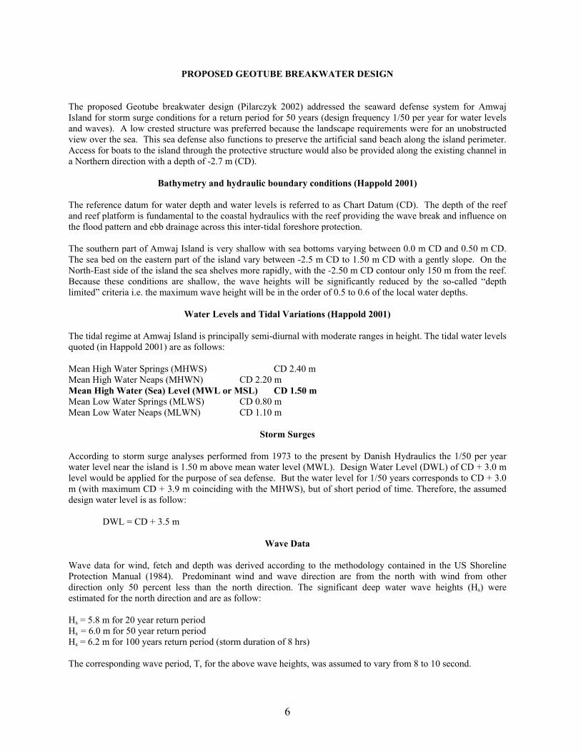
PROPOSED GEOTUBE BREAKWATER DESIGN The proposed Geotube breakwater design (Pilarczyk 2002) addressed the seaward defense system for Amwaj Island for storm surge conditions for a return period for 50 years (design frequency 1/50 per year for water levels and waves). A low crested structure was preferred because the landscape requirements were for an unobstructed view over the sea. This sea defense also functions to preserve the artificial sand beach along the island perimeter. Access for boats to the island through the protective structure would also be provided along the existing channel in a Northern direction with a depth of -2.7 m (CD).
Bathymetry and hydraulic boundary conditions (Happold 2001) The reference datum for water depth and water levels is referred to as Chart Datum (CD). The depth of the reef and reef platform is fundamental to the coastal hydraulics with the reef providing the wave break and influence on the flood pattern and ebb drainage across this inter-tidal foreshore protection. The southern part of Amwaj Island is very shallow with sea bottoms varying between 0.0 m CD and 0.50 m CD. The sea bed on the eastern part of the island vary between -2.5 m CD to 1.50 m CD with a gently slope. On the North-East side of the island the sea shelves more rapidly, with the -2.50 m CD contour only 150 m from the reef. Because these conditions are shallow, the wave heights will be significantly reduced by the so-called “depth limited” criteria i.e. the maximum wave height will be in the order of 0.5 to 0.6 of the local water depths.
Water Levels and Tidal Variations (Happold 2001) The tidal regime at Amwaj Island is principally semi-diurnal with moderate ranges in height. The tidal water levels quoted (in Happold 2001) are as follows: Mean High Water Springs (MHWS) CD 2.40 m Mean High Water Neaps (MHWN) CD 2.20 m Mean High Water (Sea) Level (MWL or MSL) CD 1.50 m Mean Low Water Springs (MLWS) CD 0.80 m Mean Low Water Neaps (MLWN) CD 1.10 m
Storm Surges According to storm surge analyses performed from 1973 to the present by Danish Hydraulics the 1/50 per year water level near the island is 1.50 m above mean water level (MWL). Design Water Level (DWL) of CD + 3.0 m level would be applied for the purpose of sea defense. But the water level for 1/50 years corresponds to CD + 3.0 m (with maximum CD + 3.9 m coinciding with the MHWS), but of short period of time. Therefore, the assumed design water level is as follow:
DWL = CD + 3.5 m
Wave Data Wave data for wind, fetch and depth was derived according to the methodology contained in the US Shoreline Protection Manual (1984). Predominant wind and wave direction are from the north with wind from other direction only 50 percent less than the north direction. The significant deep water wave heights (Hs) were estimated for the north direction and are as follow: Hs = 5.8 m for 20 year return period Hs = 6.0 m for 50 year return period Hs = 6.2 m for 100 years return period (storm duration of 8 hrs) The corresponding wave period, T, for the above wave heights, was assumed to vary from 8 to 10 second.
7
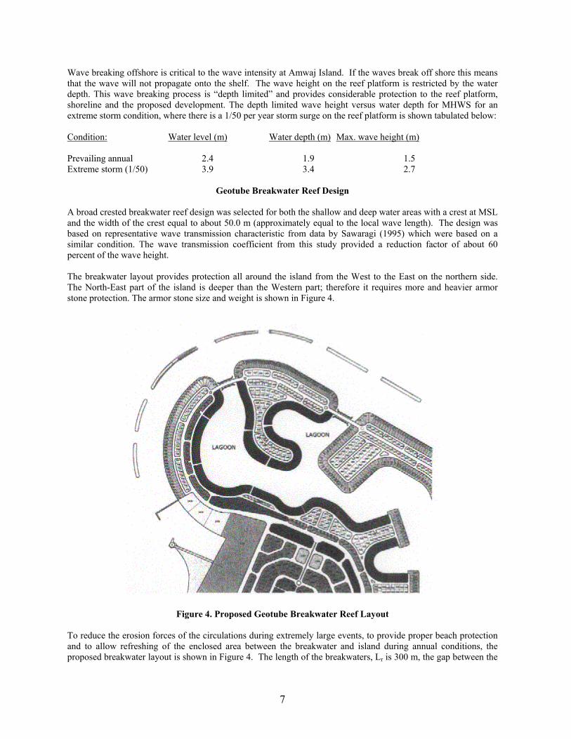
Wave breaking offshore is critical to the wave intensity at Amwaj Island. If the waves break off shore this means that the wave will not propagate onto the shelf. The wave height on the reef platform is restricted by the water depth. This wave breaking process is “depth limited” and provides considerable protection to the reef platform, shoreline and the proposed development. The depth limited wave height versus water depth for MHWS for an extreme storm condition, where there is a 1/50 per year storm surge on the reef platform is shown tabulated below: Condition: Water level (m) Water depth (m) Max. wave height (m) Prevailing annual 2.4 1.9 1.5 Extreme storm (1/50) 3.9 3.4 2.7
Geotube Breakwater Reef Design A broad crested breakwater reef design was selected for both the shallow and deep water areas with a crest at MSL and the width of the crest equal to about 50.0 m (approximately equal to the local wave length). The design was based on representative wave transmission characteristic from data by Sawaragi (1995) which were based on a similar condition. The wave transmission coefficient from this study provided a reduction factor of about 60 percent of the wave height. The breakwater layout provides protection all around the island from the West to the East on the northern side. The North-East part of the island is deeper than the Western part; therefore it requires more and heavier armor stone protection. The armor stone size and weight is shown in Figure 4.
Figure 4. Proposed Geotube Breakwater Reef Layout To reduce the erosion forces of the circulations during extremely large events, to provide proper beach protection and to allow refreshing of the enclosed area between the breakwater and island during annual conditions, the proposed breakwater layout is shown in Figure 4. The length of the breakwaters, Lr is 300 m, the gap between the

8
breakwaters, G is 0.25 times Lr or about 75 m. The distance offshore is X = Lr = 300 m. The distance to the beach shoreline is about 340 m from the hard boundary of the island. The principles and definitions of the reef design are shown in Figure 5. There are eleven 300 m long segmented Geotube breakwater reefs planned as off shore protection.
Figure 5. Principles and definitions of the Breakwater Reef Design
The final proposed Geotube breakwater reef design for the shallow and deeper areas are shown in Figure 6. The present preliminary design based on the available literature has proven that it is possible to provide the proper protection to the main island and to create recreational condition with an artificial sand beach by the use of low-crested reefs with the crest located at the Mean Water Level (MSL = CD + 1.5 m). The response of the sand beach will have to be monitored and maintained as needed. When planning these structures the maximum water level frequency for design is normally chosen at 1/50 years. The water level may reach the CD + 4.0 m and overtopping may reach a level of CD + 6.0 m. This design was very approximate and has been further improved and optimized through numerical modeling simulations and model tests conducted at the Delft Laboratories, The Netherlands. These results of this testing confirmed and verified the original Pylarczyk 2002 design and will be the subject of an original work.
GEOTUBE CONSTRUCTION Geotubes were hydraulically filled with sandy materials from the proposed navigation channels leading into the Amway Island project. The geotechnical description for the dredged material to be used to fill the Geotubes is primarily sand. The medium dense sand is slightly silty and fine to coarse grained, containing gravel size shell debris and fragments of calcarenite or carbonate sandstone. The contractor was able to locate his equipment and pump the materials that consist mostly of sand. Boring log information indicated that these materials are basically non-cohesive and settled out very rapidly.
9
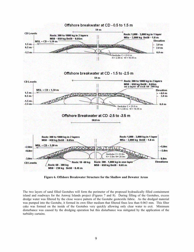
Figure 6. Offshore Breakwater Structure for the Shallow and Dewater Areas The two layers of sand filled Geotubes will form the perimeter of the proposed hydraulically filled containment island and roadways for the Amwaj Islands project (Figures 7 and 8). During filling of the Geotubes, excess dredge water was filtered by the close weave pattern of the Geotube geotextile fabric. As the dredged material was pumped into the Geotube, it formed its own filter medium that filtered fines less than 0.063 mm. This filter cake was formed on the inside of the Geotubes very quickly allowing only clear water to exit. Minimum disturbance was caused by the dredging operation but this disturbance was mitigated by the application of the turbidity curtains.

10
Figure 7. Geotube Design for the Island Perimeter and Roadways
Figure 8. Geotube Placement in the Island Perimeter
The Geotubes 13 meter circumference by 97 meter long Geotubes were manufactured at Commerce, Georgia, in the United States, by TC Nicolon Corporation and shipped to Bahrain in 40 high cube containers. The first 500 meters were by air to start the project. The Geotube were fabricated with a recently developed highly UV stabilized heavy woven polypropylene geotextile fabric, Mirafi GC1000, consisting of the following characteristics:
GEOTEXTILE PHYSICAL PROPERTIES FOR TC NICOLON GEOTUBES WOVEN POLYPROPYLENE FABRIC
MECHANICAL TEST METHOD UNIT MINIMUM AVERAGE PROPERTIES TEST VALUE VALUE Apparent Opening ASTM D 4751 U.S. Sieve #40 Permeability ASTM D 4491 sec-1 0.20 Puncture ASTM D 4833 kN (lbs) 2.67 (600) Wide Width Tensile ASTM D 4595 kN/m (lbs/in) 175 x 175 (1000 x 1000) in both principal directions Wide Width Tensile ASTM D 4595 % 15(maximum) Elongation in any Principal Direction Burst Strength ASTM D 3786 kPa (psi) 10,320 (1500) Trapezoidal Tear ASTM D 4533 kN (lbs) 2.67 x 2.67 (600 x 600) Ultraviolet Degradation ASTM D 4355 80% (percent of ultimate strength retained Seam Strength ASTM D 4884 kN/m (lbs/in) 105 x 105 (600 x 600) Weight per Square gr/m (oz/sy) 948 (28) Meter

11
GEOTUBE ISLAND AND ROADWAY DESIGN There was about 30 km of Geotubes used to construct the kidney shaped island to minimize obstruction and view of the sea. The island was designed using 13 m circumference 2.60-meter high Geotubes fabricated with a TC Nicolon GC 1000 woven polypropylene geotextile fabric. A second layer of Geotubes 2.0 m high was place on hydraulic fill placed behind the first row of Geotubes. This fabric has an Area Opening Size (AOS) of 0.425 mm or AOS or equivalent US Sieve size of a No. 40. The wide width tensile strength in the machine and cross directions was 175 kN/m. Seam strength in the principle directions was about 50 to 60 percent of these values or about105 kN/m. At a height of 2.60 meters the Geotubes contained about 11.25 cubic meters per linear meter of dredged material. The volume of material between the Geotubes depended on the width of the island sections or roadway in a particular area. Typical roadway widths were about 50.0 m. All Geotube design cross sections were designed with a computer program “Simulation of Fluid Filled Tubes for Windows,” (sofftwin) by John B. Palmerton (1999). Geotube placement began in open water on the North West portion of Amwaj Island in about 1.0 m depth of water. The sea bottom was prepared by removing all sharp objects and leveling the sea-bed as uniformly as possible to provide a constant Geotube height. The Geotube was provided with nylon seat beat straps sewn into the fabric every 5 meters along the length of the Geotube in a lay flat position. The Geotube lay flat width was 6.5 m wide and 97 m long. Polypropylene ropes were tied to each of the nylon straps and these ropes were then tied to 10 cm diameter steel post that had been driven about one meter into the sea floor. Figure 9 shows the anchors poles and ropes and the Geotube being prepared for hydraulic filling by the dredge. Because the polypropylene Geotube and ropes float the heavy fabric is very maneuverable in the sea water.
12
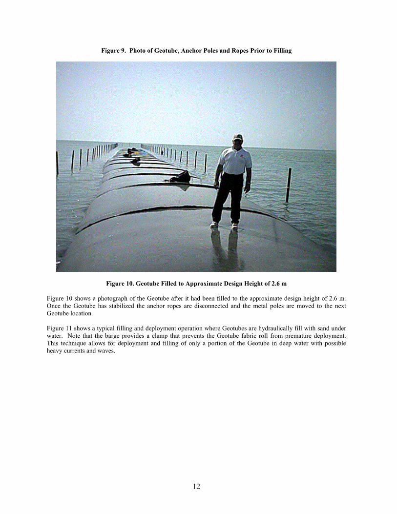
Figure 9. Photo of Geotube, Anchor Poles and Ropes Prior to Filling
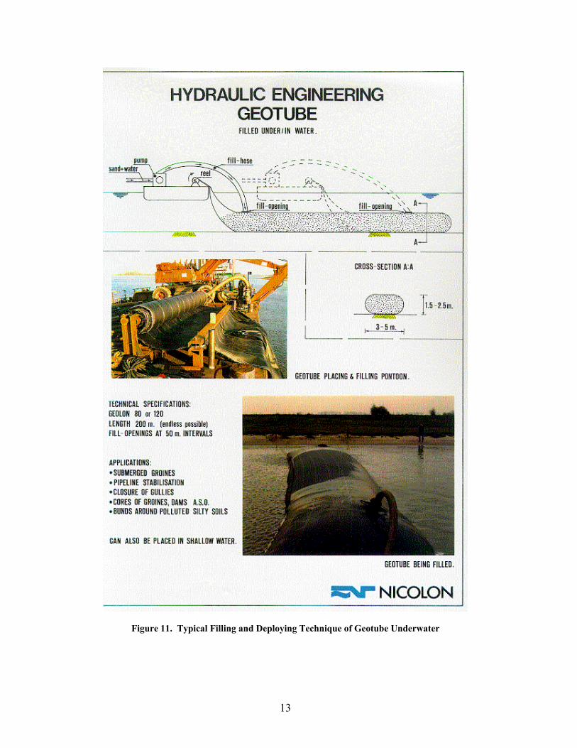
Figure 10. Geotube Filled to Approximate Design Height of 2.6 m Figure 10 shows a photograph of the Geotube after it had been filled to the approximate design height of 2.6 m. Once the Geotube has stabilized the anchor ropes are disconnected and the metal poles are moved to the next Geotube location. Figure 11 shows a typical filling and deployment operation where Geotubes are hydraulically fill with sand under water. Note that the barge provides a clamp that prevents the Geotube fabric roll from premature deployment. This technique allows for deployment and filling of only a portion of the Geotube in deep water with possible heavy currents and waves.
13
Figure 11. Typical Filling and Deploying Technique of Geotube Underwater

14
SUMMARY AND CONCLUSIONS At the time of this writing the first layer of Geotube containment for the island has been completed and the second layer is approximately 50% complete. The roadway Geotube containment is 100% complete. Dredging and filling of the island platform is more than 60% complete while the roadway is 100% complete. This first phase of work consisted of $200 million out of a total investment of $1.0 billion or 20 percent completion at this time. The offshore segmented Geotube breakwaters are scheduled for construction to start in June 2002. The entire island creation, roadway, and breakwaters are scheduled to be completed in December 2002. At the date of this writing, the project is ahead of schedule. The first community cluster of single resident shorefront housing construction is planned to begin construction May 2002. The first 160 room hotel with a private beach and is planned to start construction December 2002. According to Mario Santiago, project manager for the Amwaj Island project, the selection of the Geotube method of construction for the island containment area was primarily for expediency of construction and this has been accomplished. However, a secondary benefit was that the Geotube method has proven to be 50% more economical than the original quotation for the construction of the containment using traditional methods of rock bunds construction. Additional benefits have been in the reduced environmental impact to the aquatic habitat surrounding the site. The use of hydraulically filling Geotubes has greatly reduced the turbidity, siltation and migration of fines to the surrounding area and effects on the environment.
ACKNOWLEDGEMENTS Acknowledgements are made to the developers who are Mr. Saud Abdulaziz Kanoo, Chairman of Ossis, Mr. Khalid A. Aisharif, Vice Chairman of Ossis, Mr. Jamell A. Almatrook, Managing Director of Ossis. Acknowledgements are also made to Krystian Pilarczyk, Directorate-General for Public Works and Water Ministry of Transport, Pubilc Works and Water Mannagement, Delft, The Netherlands. Acknowledgements are also made to Pieter de Bruin, Geotube technical manager, TC Nicolon, Almelo, The Netherlands and Dan Avendano, construction manager Ossis’s Contractor for the project.
REFERENCES Happold, B. (2001). “Master Plan and Environmental Impact Assessment for Amwaj Island Development,” contract report for Ossis Property Developers Murad, M.T. (2001). Ossis Property Developers Proposed Soil Investigation at Salman Island, Bahrain, Report on Site Investigation, Report No.G/1852 April 2001 Pilarczyk, K.W. (2002). Preliminary (conceptional) design of offshore breakwaters for the Amwaj Island Project, Delft, The Netherlands, January 2001 US Army Corps of Engineers (1984), US Shoreline Protection Manual Palmerton, J.B. (1999). Simulation of Fluid Filled Tubes for Windows, Geosynthetic Applications Simulations, 13 Lake Boulevard, Vicksburg, MS 39180, [email protected]