Amperometri VDO cockpit vision international1 - laltraranda.it · Technical Product Manual VDO...
13
VDO cockpit vision / international Instruments Technical Product Manual TU00-0755-0000002 I 0607 I Technical details subject to change www.siemensvdo.com
Transcript of Amperometri VDO cockpit vision international1 - laltraranda.it · Technical Product Manual VDO...
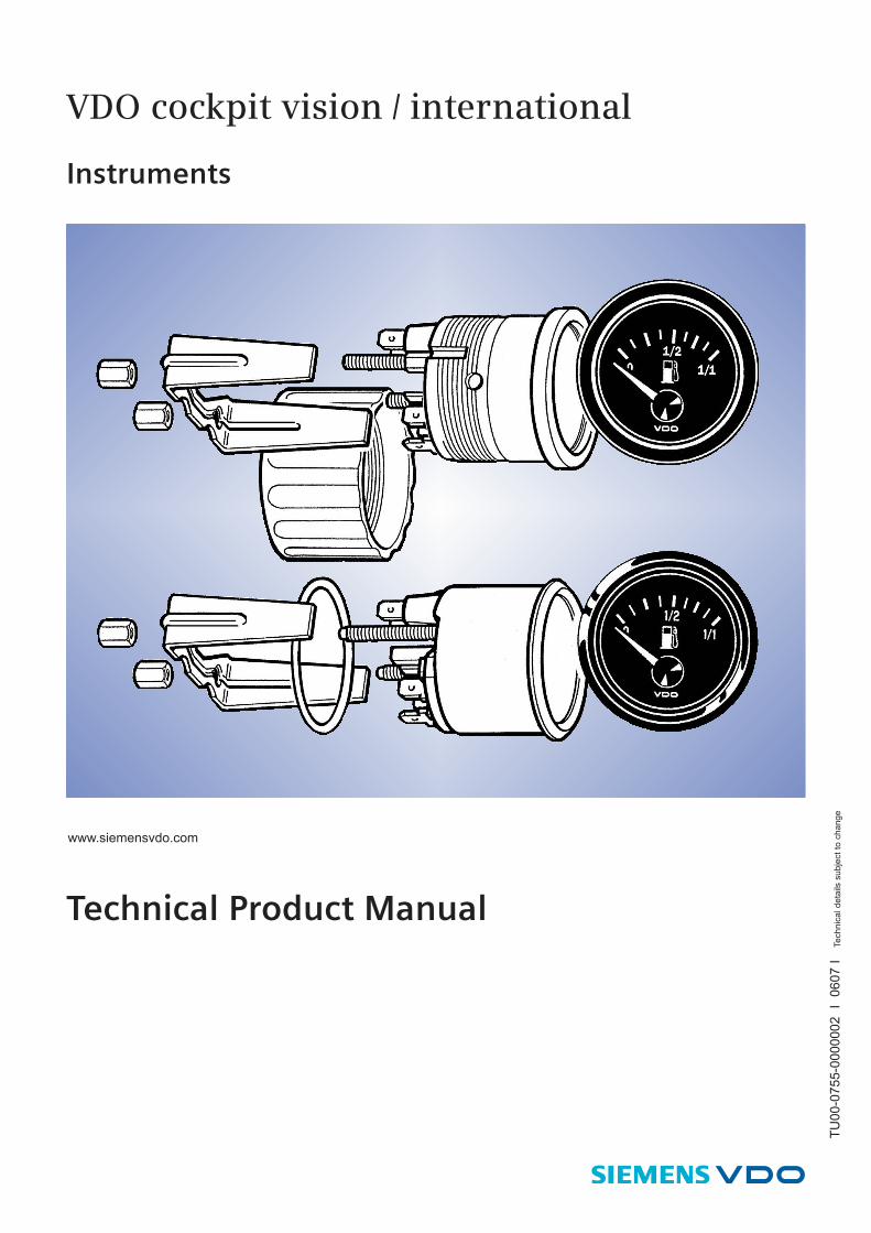
VDO cockpit vision / international
Instruments
Technical Product Manual
TU
00
-07
55
-00
00
00
2
I 0
60
7 I
Te
ch
nic
al d
eta
ils s
ubje
ct
to c
ha
ng
ewww.siemensvdo.com
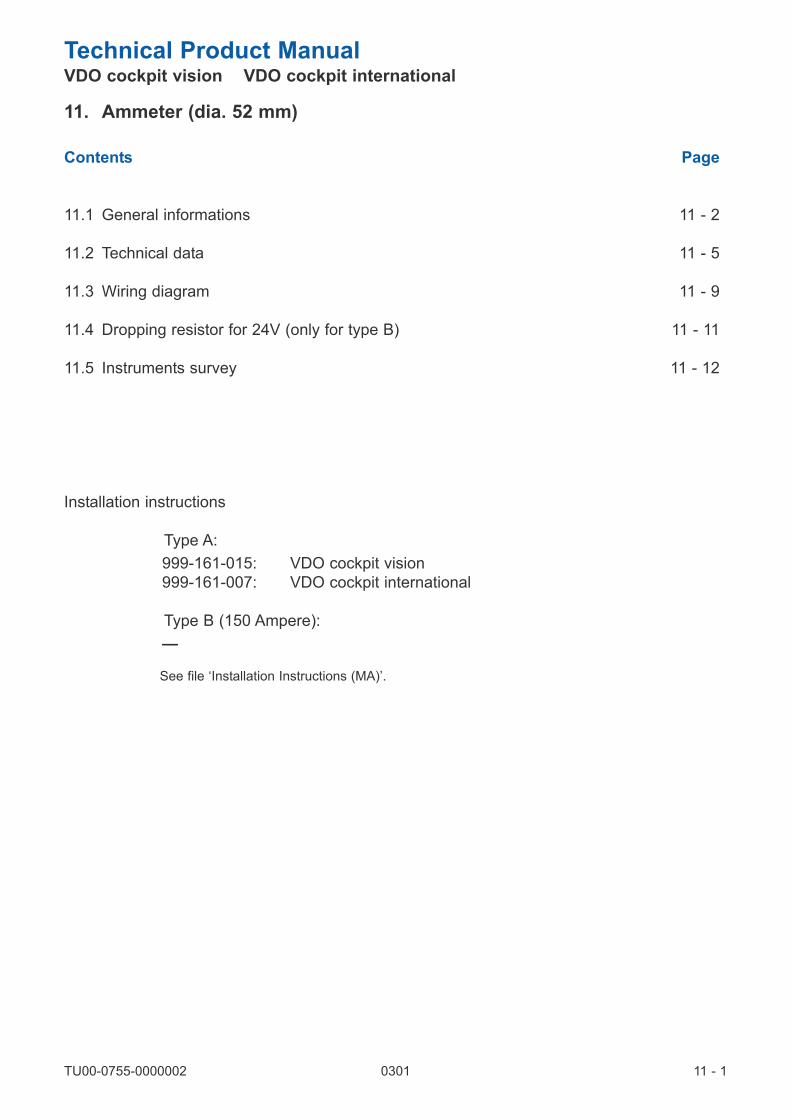
Technical Product Manual VDO cockpit vision VDO cockpit international
Contents Page
11.1 General informations 11 - 2
11.2 Technical data 11 - 5
11.3 Wiring diagram 11 - 9
11.4 Dropping resistor for 24V (only for type B) 11 - 11
11.5 Instruments survey 11 - 12
Installation instructions
Type A:
999-161-015: VDO cockpit vision
999-161-007: VDO cockpit international
Type B (150 Ampere):
—
See file ‘Installation Instructions (MA)’.
11 - 1TU00-0755-0000002 0301
11. Ammeter (dia. 52 mm)

Technical Product Manual VDO cockpit vision VDO cockpit international
11.1 General Informations
The ammeter has been designed for land-bound vehicles only (with the exception of motorcycles).
The instrument has an analog display indicating the vehicle DC current in Ampere.
There are two versions:
type A: indicating instrument for 30 Ampere, 60 Ampere or 100 Ampere.
type B: indicating instrument for 150 Ampere (accessories: shunt and wiring kit).
Illumination type A
The lamp socket is clipped in.
To replace the light bulb, carefully, with the thumb,
push the lamp holder out to the side.
Illumination type B
The lamp socket is pushed in.
To replace the light bulb simple pull the lamp holder out.
11 - 2TU00-0755-0000002 0301
11. Ammeter (dia. 52 mm)

Technical Product Manual VDO cockpit vision VDO cockpit international
11.1 General Informations
Designation of function for type A
The ammeter monitors charging and
discharging currents in the on-board
network.
For this function the ammeter is connected
to the circuit so that charging currents and
the load of all consumers, except the star-
ter motor, must pass through the ammeter.
A rotating magnet disk is placed on top of
the current-carrying bar. This disk is con-
nected to a pointer, and turns as a function
of the magnitude and direction of the cur-
rent and the resulting magnetic field.
In static condition the pointer points to zero
in the center of the graduation, the poles of
the magnetic disk being directed to two
neighboring calibration tags.
When the charging current increases, it
produces a corresponding magnetic field
around the conductor, which deflects the
pointer from its zero position into the positi-
ve range. A discharge changes the direc-
tion of the current and of the resulting mag-
netic field. The inverse magnetic force de-
flects the magnetic disk with its pointer into the negative range.
The ammeter can be adjusted for different measuring ranges by adjustment of the calibration tags. A thicker
current bar is used for measuring ranges of ± 50 A and more.
11 - 3TU00-0755-0000002 0301
11. Ammeter (dia. 52 mm)
Dial
Calibration
tab Calibration
tab
– L+ B
Magnet
(turning)
Conductor
bar
Pointer

Technical Product Manual VDO cockpit vision VDO cockpit international
11.1 General Informations
Designation of function for type B
Movement: System Ke (to 320°)
(Turning magnet ratio measuring movement, pointer deflection up to 320°)
The ammeter monitors charging and discharging
currents in the on-board network.
A turning magnet ratio measuring movement is
the main component of the ammeter. It converts
the current pulses from the shunt to an analog di-
splay on a dial. An electronic circuit converts va-
rying current pulses to unified pulses, which are
fed to the turning magnet movement. The turning
magnet ratio measuring movement applies the
principle of the current ratio of two separate coils.
Two stationary coils generate a magnetic field as
a function of the current flowing through them.
The magnetic field resulting from these two fields
moves a two-pole magnet disk carrying a pointer.
The pointer deflection is a function of the ratio of
the two currents flowing through the coils.
A shielding casing prevents the effect of external
magnetic fields.
The special electronic system controlling the mo-
vement permits a pointer deflection of 320°. The
rotation is limited by a pin on the turning magnet
moving in a groove of the coil carrier; the oppo-
sing force is generated by a spiral spring.
11 - 4TU00-0755-0000002 0301
11. Ammeter (dia. 52 mm)
Spiral spring
Coil carrier
Turning
magnet
Stop pin
Coil
Magnetic
shield

Technical Product Manual VDO cockpit vision VDO cockpit international
11.2 Technical Data
11 - 5TU00-0755-0000002 0301
11. Ammeter (dia. 52 mm)
Type A
Operating temperature: – 30°C ... + 85°C
Storage temperature: – 40°C ... + 90°C
Illumination:
(option)
1 light bulb 12 V, 2 W
or 24 V, 2 W,
2 colour caps, green and red
Protection: IP64 DIN 40050 from the front
Vibration resistance: max. 1g eff., 25 ... 2000 Hz,
duration 8 h, f: 1 octave/min.
Nominal position: NL 0 to NL 90, DIN 16257
Mounting hole: dia. 53mm
0,5 ... 8mm
Clamping width
49mm
5.4mm
72.5mm max. 61.1mm
38.5mm
M5
32mm
26mm
55.6mm
dia
. 5
2m
m
15
mm
14
mm
4m
m
11
mm
VDO cockpit vision
dia. 52 mm Backlight
Pin assignment:
+ L: Alternator (terminal B+) and
ignition switch (terminal 30)
+ B: + Battery
(starter, terminal 30)

Technical Product Manual VDO cockpit vision VDO cockpit international
11.2 Technical Data
11 - 6TU00-0755-0000002 0301
11. Ammeter (dia. 52 mm)
Type A
Operating temperature: – 30°C ... + 85°C
Storage temperature: – 40°C ... + 90°C
Illumination:
(option)
1 Light bulb 12 V, 2 W or
24 V, 2 W
Protection: IP64 DIN 40050 from the front
Vibration resistance: max. 1g eff., 25 ... 2000 Hz,
duration 8 h, f: 1 octave/min.
Nominal position: NL 0 to NL 90, DIN 16257
Mounting hole: dia. 53mm
0,5 ... 8mm
Clamping
width
49mm dia. 1.5mm
5.4mm
72.5mm max. 61.1mm
38.5mm
M5 (30/60 AMP)
M8 (100 AMP)
32mm
26mm
55.6mm
dia
. 5
2m
m
15
mm
14
mm
4m
m
11
mm
VDO cockpit international
dia. 52 mm Floodlight
Pin assignment:
+ L: Alternator (terminal B+) and
ignition switch (terminal 30)
+ B: + Battery
(starter, terminal 30)

Technical Product Manual VDO cockpit vision VDO cockpit international
11.2 Technical Data
11 - 7TU00-0755-0000002 0301
11. Ammeter (dia. 52 mm)
Type B (150 Ampere): Indicating Instrument
Mounting hole: dia. 53mm
0,5 ... 12mm 12 ... 23mm
Clamping width
52mm
5mm
60mm max.
45mm
34mm
Ø 5
8d
ia.
56
mm
Ø 5
9
VDO cockpit international
dia. 52 mm Floodlight
Pin assignment:
1: Signal +
2: Signal –
+: Battery + (12 V)
–: Battery –
Operating voltage: 10.8 V ... 16 V
Movement: System Ke (→320°)
Pickup: Shunt (not included)
50 mV at max. deflection
Current consumption: 100 mA (without illumination)
Operating temperature: – 20°C ... + 70°C
Storage temperature: – 30°C ... + 85°C
Illumination: 1 light bulb 12 V, 2 W
Protection: IP64 DIN 40050 from the front,
CE approved, reverse-polarity protection
Vibration resistance: max. 1g eff., 25 ... 2000 Hz,
duration 8 h, f: 1 octave/min.

Technical Product Manual VDO cockpit vision VDO cockpit international
11.2 Technical Data
11 - 8TU00-0755-0000002 0301
11. Ammeter (dia. 52 mm)
Type B (150 Ampere): Accessories
Shunt
Wiring Kit
(this is not part of the supply)
Part No.: X10-191-000-001
VDO cockpit international
must consist of:
1x cable,black, 1 mm2, 10 m long
1x cable, blue, 1 mm2, 10 m long
1x cable, brown, 0.75 mm2, 1 m long
1x cable, grey-red, 0.75 mm2, 1 m long
2x eyelet terminal for 16 mm2
2x eyelet erminal for 10 mm2
2x self-tapping screw, ISO 1481-ST 4.2 x 22-C-A4 (DIN 7971)
Do not shorten the black and the blue cable (10 m measuring leads).
134mm
152mm
31
mm
dia
.5.2
mm

Technical Product Manual VDO cockpit vision VDO cockpit international
11.3 Wiring Diagram
Type A: basic wiring diagram
The instrument is connected to the circuit to have
the charging current and the load of all consumers,
except the starter motor, flowing through the amme-
ter.
The newly installed cable should have the same
section as the available one, but at least:
6 mm2 for measuring range ± 30 Ampere
16 mm2 for measuring range ± 60 Ampere
35 mm2 for measuring range ± 100 Ampere.
Connect the cable to the eyelet terminal.
11 - 9TU00-0755-0000002 0301
11. Ammeter (dia. 52 mm)
Ignition
switch
Consumer
Starter motor
Alternator
Ignition switchConsumer
Starter motor
Alternator

Technical Product Manual VDO cockpit vision VDO cockpit international
11.3 Wiring Diagram
Type B (150 Ampere): Basic Wiring Diagram
Do not reduce the existing cable cross section.
Wiring kit cables:
a = blue, 1 mm2, 10 m
b = black, 1 mm2, 10 m
c = grey-red, 0.75 mm2, 1 m
d = brown, 0.75 mm2, 1 m
Do not shorten the blue and the black
cable (10 m measuring leads).
11 - 10TU00-0755-0000002 0301
11. Ammeter (dia. 52 mm)
Ignition switch
Consumer
Consumer
Starter
motor
Alternator
Ignition
switch
Consumer
Consumer
Starter
motorAlternator
58
15
30
12 V
Shunt
58
15
30
12 V

Technical Product Manual VDO cockpit vision VDO cockpit international
11.4 Dropping Resistor for 24 V
Only for type B (150 Ampere)
The ammeter type B (nominal voltage 12 V) can also be used with a nominal voltage of 24 V if an external drop-
ping resistor (option) is installed in the ground line (terminal – 31).
Connect this dropping resistor directly to pin – of the instrument, then connected it to the ground cable (d).
In this case the operating voltage range is 21 V to 32 V.
Replace 12 V light bulb by 24 V light bulb.
Dropping resistor
Part No.: 800-005-027G
The dropping resistor is supplied with
24 V 2 W light bulb.
Do not reduce the existing cable cross
section.
Wiring kit cables:
a = blue, 1 mm2, 10 m
b = black, 1 mm2, 10 m
c = grey-red, 0.75 mm2, 1 m
d = brown, 0.75 mm2, 1 m
Do not shorten the blue and the black
cable (10 m measuring leads).
11 - 11TU00-0755-0000002 0301
11. Ammeter (dia. 52 mm)
Ignition
switch
Consumer
Consumer
Rv
Starter
motorAlternator
Shunt
58
15
30
24 V
Basic wiring diagram
Rv = dropping resistor

Technical Product Manual VDO cockpit vision VDO cockpit international
11.5 Instruments Survey
VDO cockpit vision (Backlight) dia. 52 mm
Type A Part No. 190-077-. . .
VDO cockpit international (Floodlight) dia. 52 mm
Type A Part No. 190-037-. . .
VDO cockpit international (Floodlight) dia. 52 mm
Type B Part No. 190-035-. . .
11 - 12TU00-0755-0000002 0301
11. Ammeter (dia. 52 mm)
Range Imprint
– 30 ... + 30 Amp. – AMP + Metal housing 12 V 001K
– 60 ... + 60 Amp. – AMP + Metal housing 12 V 002K
DialSpecial feature Part No.
Range Imprint
– 30 ... + 30 Amp. – AMP + Metal housing 12 V001C
001G
– 60 ... + 60 Amp. – AMP + Metal housing 12 V002C
002G
– 100 ... + 100 Amp. – AMP + Metal housing 12 V003C
003G
DialSpecial feature Part No.
Range Imprint
– 150 ... + 150 Amp.AMP
– 15 ... + 15 x10
Plastic housing,
clamp ring 12 V005C
DialSpecial feature Part No.