AMI-AS230 Single Phase Meter - Camax UK Ltd · AMI AS230 Single Phase Meter Operating & Maintenance...
73
AMI-AS230 Single Phase Meter M200 001 2 5.2009
Transcript of AMI-AS230 Single Phase Meter - Camax UK Ltd · AMI AS230 Single Phase Meter Operating & Maintenance...

AMI-AS230 Single Phase Meter
M200 001 2
5.2009


AMI AS230 Single Phase Meter
Operating & Maintenance Instructions
M200 001 2B
5.2009


AS230 - AMI Single Phase Meter 1
© Elster Metering Limited - M200 001 2B - 5.2009
Contents
1 FOREWORD ................................................................................................................................... 5
2 WARNINGS..................................................................................................................................... 6
3 COMPLIANCE WITH STANDARDS AND EUROPEAN DIRECTIVES .......................................... 7
4 APPROVALS .................................................................................................................................. 7
5 INTRODUCTION............................................................................................................................. 8
6 GENERAL DESCRIPTION ........................................................................................................... 10 6.1 Basic Meter Types......................................................................................................................... 10 6.2 Current and Voltage Ratings ......................................................................................................... 10 6.3 Terminal Arrangements ................................................................................................................. 10 6.4 Active Energy Measurement Configuration ................................................................................... 10 6.5 Meter Accuracy.............................................................................................................................. 11 6.6 Meter Case ................................................................................................................................... 11
7 TEST INDICATORS & ANTI-CREEP............................................................................................ 12
8 FEATURES ................................................................................................................................... 13 8.1 Registration of Quantities .............................................................................................................. 13 8.1.1 kWh (Active Energy)...................................................................................................................... 13 8.1.2 kvarh (Reactive Energy) ............................................................................................................... 13 8.1.3 kVAh (Apparent Energy)................................................................................................................ 13 8.1.4 Demand Registers......................................................................................................................... 13 8.1.5 External Registers ......................................................................................................................... 14
9 TARIFF STRUCTURE................................................................................................................... 14 9.1 Time-of-use Energy Registers ....................................................................................................... 14 9.2 Maximum Demand Register .......................................................................................................... 15 9.3 Switching Times ............................................................................................................................ 15 9.4 Seasons and Change of Season Dates......................................................................................... 16 9.5 Exclusion Dates............................................................................................................................. 16 9.6 End of Billing ................................................................................................................................. 17 9.7 Daylight Savings............................................................................................................................ 18 9.8 Independent Day Control............................................................................................................... 18 9.9 Deferred Tariff and Deferred Tariff Changeover Date ................................................................... 18 9.10 Tariff/Display Scheme Verification................................................................................................. 19 9.11 Historical Data/Daily Billing............................................................................................................ 19 9.11.1 Historical Data ............................................................................................................................... 19 9.11.2 Daily Billing ................................................................................................................................... 19
10 INSTRUMENTATION.................................................................................................................... 19
11 LOAD/INSTRUMENTATION PROFILE RECORDING ................................................................. 20 11.1 Load Profiling................................................................................................................................. 20 11.2 Instrumentation Profiling................................................................................................................ 20 11.3 Load/Instrumentation Profile Settings............................................................................................ 21
12 SECURITY FEATURES ................................................................................................................ 22 12.1 Password Protection...................................................................................................................... 22 12.2 Data Retention............................................................................................................................... 22 12.3 Recordable Security Features ....................................................................................................... 22 12.3.1 Reverse Energy Flow .................................................................................................................... 22 12.3.2 Power Fail ..................................................................................................................................... 23 12.3.3 Long Power Fail Event .................................................................................................................. 23 12.3.4 End of Billing Event ....................................................................................................................... 23 12.3.5 Programming Event Log................................................................................................................ 23 12.3.6 Watchdog (Transient Reset).......................................................................................................... 23 12.3.7 Meter Errors................................................................................................................................... 23
AS230 - AMI Single Phase Meter
© Elster Metering Limited - M200 001 2B - 5.2009
12.3.8 Main Cover Removal Detection ..................................................................................................... 24 12.3.9 Terminal Cover Removal Detection............................................................................................... 24 12.3.10 Contactor Remote Reconnect/Disconnect Logs............................................................................ 24 12.3.11 Magnetic Manipulation Detection................................................................................................... 24 12.3.12 Firmware Checksum...................................................................................................................... 24 12.3.13 Firmware Download Log................................................................................................................ 24 12.3.14 Battery Voltage Monitoring ............................................................................................................ 24 12.3.15 Over-Voltage Events ..................................................................................................................... 25 12.3.16 Under-Voltage Events ................................................................................................................... 25 12.4 Additional Security Features.......................................................................................................... 25 12.4.1 In Service Hours ............................................................................................................................ 25 12.4.2 Remaining Internal Battery Life ..................................................................................................... 25
13 METER DISPLAY ......................................................................................................................... 26 13.1 Introduction ................................................................................................................................... 26 13.2 General ......................................................................................................................................... 26 13.3 Display Modes............................................................................................................................... 27 13.3.1 Auto-cycle Mode............................................................................................................................ 27 13.3.2 Manual Mode................................................................................................................................. 28 13.3.3 Utility Mode.................................................................................................................................... 28 13.3.4 English Display .............................................................................................................................. 29 13.3.5 OBIS Display ................................................................................................................................. 29 13.4 Displayable Data ........................................................................................................................... 30 13.5 Dial Test ........................................................................................................................................ 30 13.6 Display Indicators .......................................................................................................................... 30
14 USING THE PUSHBUTTON ......................................................................................................... 31
15 COMMUNICATIONS..................................................................................................................... 32 15.1 Local Communications Port........................................................................................................... 32 15.2 Module Communications ............................................................................................................... 32 15.2.1 WAN/HAN Signal Strength ............................................................................................................ 32
16 CONTACTOR................................................................................................................................ 33 16.1 Local/Remote Disconnection......................................................................................................... 33 16.2 Load Limiting ................................................................................................................................. 33 16.2.1 Parameters .................................................................................................................................... 33 16.3 Closing the Contactor Using the Pushbutton................................................................................. 33 16.4 Closing the Contactor by Remote Control ..................................................................................... 34 16.5 Power Outages.............................................................................................................................. 34 16.6 Event Logs ................................................................................................................................... 34
17 PROGRAMMING THE METER..................................................................................................... 35
18 REAL TIME CLOCK AND CALENDAR........................................................................................ 35
19 BATTERY BACK-UP .................................................................................................................... 35 19.1 Internal Battery .............................................................................................................................. 35 19.1.1 Internal Battery Monitoring ............................................................................................................ 36
20 AUXILIARY OUTPUT ................................................................................................................... 37 20.1 SO Output (Optional)..................................................................................................................... 37 20.2 Relay Output (Optional) ................................................................................................................. 37
21 TECHNICAL DATA....................................................................................................................... 38 21.1 AS230 Meter.................................................................................................................................. 38 21.2 Contactor ................................................................................................................................... 39

Operating & Maintenance Instructions 3
22 INSTALLATION ............................................................................................................................ 40 22.1 Unpacking ..................................................................................................................................... 40 22.2 Handling ........................................................................................................................................ 40 22.3 Storage ........................................................................................................................................ 40 22.4 Installation Site .............................................................................................................................. 40 22.5 Electromagnetic Compatibility (EMC) ............................................................................................ 40 22.6 Fixing and Connection................................................................................................................... 41
23 COMMISSIONING......................................................................................................................... 42
24 MAINTENANCE............................................................................................................................ 43
25 DISPOSAL AND RECYCLING ..................................................................................................... 43 FIGURE 1 - MODEL CODE ............................................................................................................................... 44 FIGURE 1A - MODEL CODE (CONTINUED) ........................................................................................................... 45 FIGURE 2 - BS AS230 WITH MODULE FITTED (LONG TERMINAL COVER) ............................................................. 46 FIGURE 2A - METER MODULE HOUSING (SHORT TERMINAL COVER)...................................................................... 47 FIGURE 3 - TYPICAL NAMEPLATE ..................................................................................................................... 48 FIGURE 4 - LOAD CURVES............................................................................................................................... 49 FIGURE 5 - TERMINAL ARRANGEMENTS ............................................................................................................ 50 FIGURE 5A - TERMINAL CONFIGURATIONS........................................................................................................... 51 FIGURE 6 - DIMENSIONS AND FIXING CENTRES (BS).......................................................................................... 52 FIGURE 6A - DIMENSIONS AND FIXING CENTRES (DIN) ........................................................................................ 53 FIGURE 7 - DISPLAYS ................................................................................................................................... 54 FIGURE 7 - DISPLAYS (CONTINUED).................................................................................................................. 55 FIGURE 7A - DISPLAY MODES............................................................................................................................ 56 FIGURE 8 - DISPLAY TABLE ............................................................................................................................. 57 FIGURE 8A - DISPLAY TABLE (CONTINUED).......................................................................................................... 58 FIGURE 8B - DISPLAY TABLE (CONTINUED........................................................................................................... 60 FIGURE 8C - DISPLAY TABLE (CONTINUED).......................................................................................................... 61 FIGURE 9 - CONTACTOR OPERATION................................................................................................................ 62 FIGURE 10 - PASSWORD ACCESS LEVELS .......................................................................................................... 63
APPENDIX A - CHECKING KWH AND KVARH REGISTRATION ACCURACY........................................... 64 A1 INTRODUCTION................................................................................................................................. 64 A2 CHECKING METER ACCURACY USING THE LED TEST INDICATOR .......................................................... 64 A2.1 Comparing the number of LED pulses with substandard meter register advance ......................... 64 A2.2 Comparing LED pulses with substandard meter pulses ................................................................ 65 A3 CHECKING METER REGISTRATION ACCURACY FROM REGISTER ADVANCES............................................ 65 A3.1 Using the 'Dial Test' values on the meter display .......................................................................... 65

AS230 - AMI Single Phase Meter
© Elster Metering Limited - M200 001 2B - 5.2009

Operating & Maintenance Instructions 5
1 FOREWORD
HEALTH AND SAFETY
Compliance with Instructions in this Manual The instructions and information in this manual are provided in compliance with Section 6 of the UK Health and Safety at Work Act, as amended by Schedule 3 of the Consumer Protection Act 1987.
The purchaser is responsible for making sure that everyone, whether in his employment or not, who will be associated with the products supplied by Elster Metering Systems, and to which these instructions and information apply, are made familiar with the contents of this manual.
This applies to all persons who may be involved in activities such as unpacking, inspecting, testing, setting, cleaning, installing, commissioning, operating, maintaining, decommissioning or disposing of the products.
Safety of Persons using Electrical Products Employers have a duty to ensure, as far as is reasonably practicable, the Health, Safety and Welfare at Work of all their employees. Employers must therefore ensure that employees are informed, trained and supervised and use proper working procedures to ensure the safety of themselves and others.
The information provided in this manual is intended to ensure that products are properly installed and otherwise handled in order to maintain them in a safe condition.
In the UK, employers have duties under the Health and Safety at Work Act 1974 and the various regulations stemming therefrom.
In countries outside the UK, employers should ensure proper compliance with the Health and Safety Legislation that is applicable to them.
Putting into Service Products supplied by Elster Metering Systems have been designed and manufactured, in accordance with appropriate standards, to operate under specified conditions, when properly installed.
The purchaser or delegated contractor is responsible for the "Putting into Service" of any Elster Metering Systems products that have been supplied as "Non-connected". All related activities must therefore be carried out with due regard to any applicable legislation, standards and good practice.

AS230 - AMI Single Phase Meter
© Elster Metering Limited - M200 001 2B - 5.2009
2 WARNINGS
WARNINGS
Internal Electronic Circuits Parts of the internal electronic circuits of these meters are, due to technical necessity, connected to PHASE VOLTAGES.
Removal of Covers All supplies connected to the meter should be isolated before any attempt is made to remove the meter terminal cover. Failure to do so may result in electric shock or death.
Live parts will be exposed when the terminal cover or main cover is removed.
Removal of the communications module is permissible whilst the meter is still energised. The mains terminals are finger safe.
Removal of the main cover invalidates the certification of certified meters.
Liquid Crystal Display Liquid crystals are toxic. If a display is damaged, avoid contact with the liquid. If the liquid makes contact with the skin it must be washed off immediately with water.
Seek medical advice.
Batteries The meter contains an internal 3.0V Lithium Coin Cell (or optionally a ½ AA 3.6V Lithium Cell). These batteries are completely safe under normal conditions. However, they must never be recharged, disassembled, short-circuited, heated above 100° C, incinerated, or have the contents exposed to water.
Fire, explosion or severe burns may result if these instructions are disregarded.
In the interests of safety, environmental protection and relevant legislation, Lithium batteries require careful disposal. Before arranging for the disposal of these cells, users should satisfy themselves that the proposed means of disposal is both safe and compliant with local legislation requirements.
Elster Metering Systems would like to draw the user's attention to the International Standard for Lithium Batteries - IEC 60084-4 - which gives further information about the handling, storage, transport and disposal of lithium cells.
Elster Metering Systems should be contacted by the user should difficulties arise in arranging proper disposal. They will if practical help the user identify safe disposal means.

Operating & Maintenance Instructions 7
3 COMPLIANCE WITH STANDARDS AND EUROPEAN DIRECTIVES Meters are marked with the European CE mark, in accordance with the Marking Directive 93/68/EEC, to indicate compliance with the requirements of the EMC Directive 2004/108/EC and Measuring Instruments Directive 2004/22/EC.
The CE Mark does not denote compliance with the European Low Voltage Directive 2006/95/EC, which specifically excludes electricity meters.
Safety requirements for meters are addressed in specific metering standards outlined below.
EN 50470-1 and IEC 62052-11 (General requirements)
EN 50470-3 (Active energy Class A or Class B)
IEC 62053-21 (Active energy Class 1 or Class 2)
EN 62053-23 (Reactive energy Class 2 or Class 3)
IEC 62056-61 (Display OBIS Identification Codes)
IEC 60529 (Ingress protection to IP53)
BS 7856 ( BS meter dimensional requirements)
DIN 43857 (DIN meter dimensional requirements)
The meter complies with the general requirements and particular requirements of EN 50470 Parts 1 & 3, and complies with Class M2 Mechanical environment and Class E2 Electromagnetic Environment
Devices for metering and billing electrical energy described in this manual are supplied for use in a ‘Fixed Installation’ only. Devices described are a ‘component of a system only’ and therefore outside the scope of European Directives 2002/95/EC RoHS (Restriction of the Use of Certain Hazardous Substances in Electrical Equipment) and 2002/96/EC WEEE (Waste Electrical and Electronic Equipment).
4 APPROVALS Type approval under the Measuring Instruments Directive has been given by the UK Notified Body following assessment against the standard listed above.

AS230 - AMI Single Phase Meter
© Elster Metering Limited - M200 001 2B - 5.2009
5 INTRODUCTION
The AS230 multi-tariff residential smart meter offers flexible module communications allowing the meter to interface directly to the utility via a wide area network (WAN) and to connect to a consumer's Home Automation Network (HAN).
A module supports both WAN/LAN and HAN communications. The Module is designed specifically for the application (WAN/LAN- GSM, PLC etc) and may be installed or exchanged without breaking the metrology seals on the meter's main cover. Information on the communications modules can be found in manual M200 001 3.
Local communications are provided via the optical (IEC 62056-21) port. The local port and module port can be used to program the meter and read the meter data. The AS230 records up to 4-channels of load profile data and up to eight channels of instrumentation profile data with independent integration periods. Instrumentation values may be displayed to aid meter commissioning.
The meter provides extensive security features including a programming log with user ID. Terminal cover and main cover removal detection can be provided as an option. A further option allows the meter contactor to be disconnected remotely using commands via the Module port or locally using the optical port.
The Liquid Crystal Display has large characters that can be viewed from a wide angle. The display sequence is programmable and is supported by three modes of operation, auto-cycle, manual and utility. Displayed information can have English language identifiers or OBIS (Object Identification System) codes. The OBIS codes can be changed using the Power Master Unit.
Power Master Unit Software (See Chapter M200 1001 4) provides a user-friendly WindowsTM graphical interface for programming the meter and reading meter data.
The meters are approved to:
EC Directive 2004/22/EC (MID) - EN 50470-1, EN 50470-3 Class A or Class B IEC 62053-21 accuracy Class 1 or Class 2 IEC 62053-23 for kvarh accuracy Class 2 or Class 3
The meter has an ingress protection rating of IP53 to IEC 60529

Operating & Maintenance Instructions 9
Features • IEC 62053-21: Accuracy Class 1 or Class 2 (kWh) • EC Directive 2004/22/EC (MID): Class A or Class B • IEC 62053-23: Accuracy Class 2 or Class 3 kvarh • kWh, kvarh and kVAh energy measurement • Import/export measurement • Modular WAN/LAN capability • Home Automation Network (HAN) allowing Access to: gas, water, other meter data and a
customer display • Comprehensive tariff structure • Maximum demand • Load profile recording • Instrumentation • Instrumentation profiling • Extensive security features • Product life 20 years • Optical communications port • Internal clock with battery back-up • Compact design • IP53 in accordance with IEC 60529
Options • DIN or BS case • Modular remote communications • Internal disconnect contactor • SO pulsed output • 100mA relay output
Tariff Structure • 8 time-of-use (TOU) registers • 1 Maximum demand register • 12 Seasons • 24 Change of season dates • 48 Switching times • 32 Exclusion Dates • 13 End of billing dates • Daily billing • Daylight savings • Deferred tariff
AS230 - AMI Single Phase Meter
© Elster Metering Limited - M200 001 2B - 5.2009
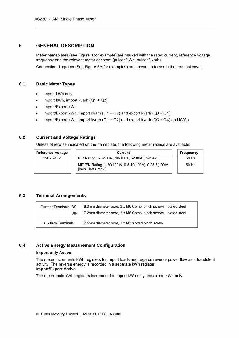
6 GENERAL DESCRIPTION
Meter nameplates (see Figure 3 for example) are marked with the rated current, reference voltage, frequency and the relevant meter constant (pulses/kWh, pulses/kvarh).
Connection diagrams (See Figure 5A for examples) are shown underneath the terminal cover.
6.1 Basic Meter Types • Import kWh only • Import kWh, import kvarh (Q1 + Q2) • Import/Export kWh • Import/Export kWh, import kvarh (Q1 + Q2) and export kvarh (Q3 + Q4) • Import/Export kWh, import kvarh (Q1 + Q2) and export kvarh (Q3 + Q4) and kVAh
6.2 Current and Voltage Ratings Unless otherwise indicated on the nameplate, the following meter ratings are available:
Reference Voltage Current Frequency 220 - 240V IEC Rating 20-100A , 10-100A, 5-100A [Ib-Imax]
MID/EN Rating 1-20(100)A, 0.5-10(100A), 0.25-5(100)A [Imin - Iref (Imax)]
50 Hz
50 Hz
6.3 Terminal Arrangements
Current Terminals BS
DIN
8.0mm diameter bore, 2 x M6 Combi pinch screws, plated steel
7.2mm diameter bore, 2 x M6 Combi pinch screws, plated steel
Auxiliary Terminals 2.5mm diameter bore, 1 x M3 slotted pinch screw
6.4 Active Energy Measurement Configuration Import only Active
The meter increments kWh registers for import loads and regards reverse power flow as a fraudulent activity. The reverse energy is recorded in a separate kWh register. Import/Export Active
The meter main kWh registers increment for import kWh only and export kWh only.
Operating & Maintenance Instructions 11
Power Flow Insensitive Mode
Power Flow Insensitive Mode is a manufacturing option that allows the meter to increment its main import kWh register regardless of whether the meter is measuring import or export energy.
When this option is enabled, the pulsing LED indicates identically for both import and export.
The Reverse Energy Event Alarm, Reverse Energy Count and Reverse kWh Register respond only to reverse power flow and continue to function as in normal operation.
Power flow insensitive mode is enabled at manufacture only.
Note: Power Flow Insensitive Mode may not be allowed in certain countries due to local regulations.
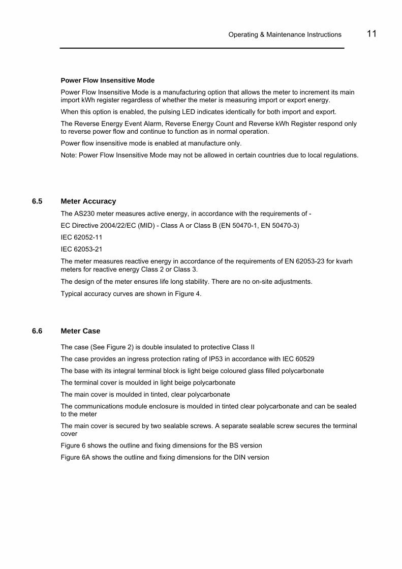
6.5 Meter Accuracy
The AS230 meter measures active energy, in accordance with the requirements of -
EC Directive 2004/22/EC (MID) - Class A or Class B (EN 50470-1, EN 50470-3)
IEC 62052-11
IEC 62053-21
The meter measures reactive energy in accordance of the requirements of EN 62053-23 for kvarh meters for reactive energy Class 2 or Class 3.
The design of the meter ensures life long stability. There are no on-site adjustments.
Typical accuracy curves are shown in Figure 4.
6.6 Meter Case
The case (See Figure 2) is double insulated to protective Class II
The case provides an ingress protection rating of IP53 in accordance with IEC 60529
The base with its integral terminal block is light beige coloured glass filled polycarbonate
The terminal cover is moulded in light beige polycarbonate
The main cover is moulded in tinted, clear polycarbonate
The communications module enclosure is moulded in tinted clear polycarbonate and can be sealed to the meter
The main cover is secured by two sealable screws. A separate sealable screw secures the terminal cover
Figure 6 shows the outline and fixing dimensions for the BS version
Figure 6A shows the outline and fixing dimensions for the DIN version

AS230 - AMI Single Phase Meter
© Elster Metering Limited - M200 001 2B - 5.2009
7 TEST INDICATORS & ANTI-CREEP
Test Indicators
A red kWh test output LED is provided which pulses in accordance to the following configurations:
Import only meter - The LED pulses for import active energy only. The LED is 'On' for reverse active energy
Import meter with Power Flow Insensitive enabled - The LED pulses for import and export active energy
Import/export meter - The LED pulses for import and export active energy
A second red kvarh test LED is provided which pulses for the following configurations:
Import only meter - The LED pulses for import reactive energy only. The LED is 'On' for reverse reactive energy
Import meter with Power Flow Insensitive enabled - The LED pulses for import and export reactive energy
Import/export meter - The LED pulses for import and export reactive energy
The LEDs are not modulated.
The pulse rate and duration configured applies to the active and reactive energy indicator
The Test Indicator pulse rate is set at manufacture to 2000 (exceptionally 1000) pulses/kWh (kvarh). The pulse width is 10ms.
Where fitted the optional pulse output will mimic the meter kWh test LED.
Anti-creep
The Wh and varh anti-creep thresholds are set at manufacture.
The kWh test LED is continuously illuminated when the active energy anti-creep lock is operating.
The kvarh test LED is continuously illuminated when the reactive energy anti-creep lock is operating.
No anti-creep lock is provided for kVAh registration.

Operating & Maintenance Instructions 13
8 FEATURES
The meter contains numerous features, combinations of which can be selected to provide the required metering function. Programmable features are selected using Power Master Unit Software that runs on an IBM or compatible PC.
This software is available from Elster Metering Systems and is described in manual M200 001 4.
Note: The features available will depend on the meter variant.
8.1 Registration of Quantities 8.1.1 kWh (Active Energy)
• kWh import
• kWh export
Total import and total export quantities are registered separately. The measurement discrimination is such that as the power factor of any load from 0.05Ib to Imax is varied over 360°, the import and export registers will never advance together. The resolution of registration is 1mWh.
See Section 6.4 for import/export options.
8.1.2 kvarh (Reactive Energy)
• Q1 kvarh Inductive Import
• Q2 kvarh Capacitive Import
• Q3 kvarh Inductive Export
• Q4 kvarh Capacitive Export
• Q1 + Q2 Import kvarh
• Q3 + Q4 Export kvarh
All four quadrants are registered separately. The resolution of registration is 1mvarh.
kvarh is derived using the phase shift method.
Note: The diagram shows a representation of the quadrants. The quadrant of the present load can be shown on the display.
8.1.3 kVAh (Apparent Energy) kVAh is derived from the measured Wh and varh values
The calculation uses the formula: VAh = √ ([Wh]2 + [varh]2 )
8.1.4 Demand Registers A Demand Register is associated with each of the metered quantities detailed above. The Demand integration period is configurable to 1, 2, 3, 4, 5, 6, 10, 15, 20, 30 or 60 minutes (Note that the Demand Integration Period is the same as the Load Profile Integration Period).
E
XPO
RT A
CTIV
E PO
WER
I
MPORT REACTIVE POWER
EXPORT REACTIVE POWER
Q1Q2
Q3 Q4
+Q
-Q
+P-P
Lagging/Indu
ctive
Lea
ding
/Cap
acitiv
e
Lagging/Inductive Leading/Capacitive
AS230 - AMI Single Phase Meter
© Elster Metering Limited - M200 001 2B - 5.2009
Demand = Energy recoded in demand period * ( 60 ) Demand period duration in minutes
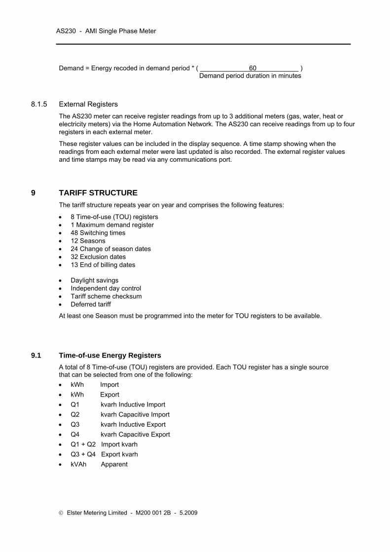
8.1.5 External Registers The AS230 meter can receive register readings from up to 3 additional meters (gas, water, heat or electricity meters) via the Home Automation Network. The AS230 can receive readings from up to four registers in each external meter.
These register values can be included in the display sequence. A time stamp showing when the readings from each external meter were last updated is also recorded. The external register values and time stamps may be read via any communications port.
9 TARIFF STRUCTURE The tariff structure repeats year on year and comprises the following features:
• 8 Time-of-use (TOU) registers • 1 Maximum demand register • 48 Switching times • 12 Seasons • 24 Change of season dates • 32 Exclusion dates • 13 End of billing dates • Daylight savings • Independent day control • Tariff scheme checksum • Deferred tariff
At least one Season must be programmed into the meter for TOU registers to be available.
9.1 Time-of-use Energy Registers A total of 8 Time-of-use (TOU) registers are provided. Each TOU register has a single source that can be selected from one of the following: • kWh Import • kWh Export • Q1 kvarh Inductive Import • Q2 kvarh Capacitive Import • Q3 kvarh Inductive Export • Q4 kvarh Capacitive Export • Q1 + Q2 Import kvarh • Q3 + Q4 Export kvarh • kVAh Apparent

Operating & Maintenance Instructions 15
Each TOU Register is independently time controlled so that registration can take place over a restricted time period.
The contents of each TOU Register can be viewed on the display along with the active rate(s).
9.2 Time-of Use Maximum Demand Register
The meter has one maximum demand register which records data over periods defined by the time-of-use programme. The following data is recorded:
• Register source
• Time/date stamp of the maximum demand
• Maximum demand value
This data set can be viewed on the display The maximum demand can be sourced from any register defined under Time-of-Use Registers (See Section 9.1)
Cumulative Maximum Demand Register
At the end of each Billing Period the value of the Maximum Demand Register is added to the Cumulative Maximum Demand Register. The Maximum Demand Register is then set to zero.
9.3 Switching Times
Up to 48 switching times can be set, each allocated to a specified season. Each switching event can be enabled for any combination of days of the week. These are the transition times when one or more TOU registers become active or inactive.
Each switching time is defined in hours and minutes. A 24-hour clock is used.
The above diagram shows the tariff for TOU 1 and TOU 2. TOU 1 is active from 06:00 to 18:00. TOU 2 is active from 18:00 to 06:00. It is possible for none or multiple TOU registers to be programmed to be active at any particular time.
06:00 18:00
24 hours
Switching times
AS230 - AMI Single Phase Meter
© Elster Metering Limited - M200 001 2B - 5.2009
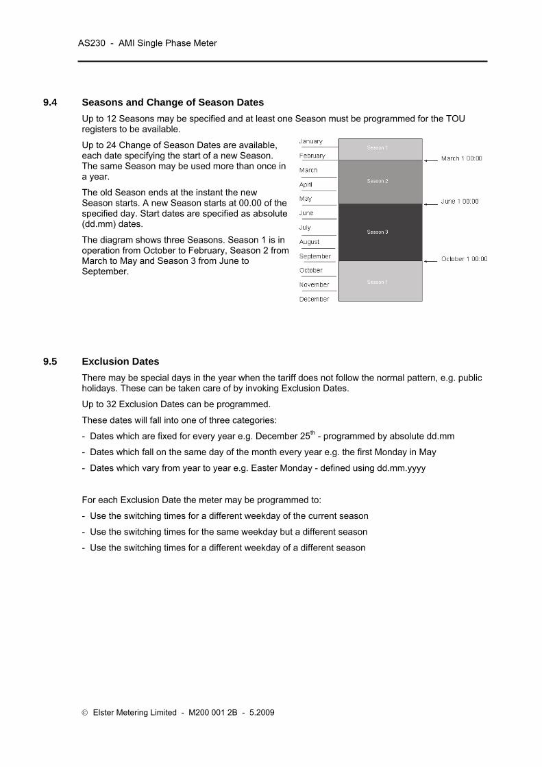
9.4 Seasons and Change of Season Dates Up to 12 Seasons may be specified and at least one Season must be programmed for the TOU registers to be available.
Up to 24 Change of Season Dates are available, each date specifying the start of a new Season. The same Season may be used more than once in a year.
The old Season ends at the instant the new Season starts. A new Season starts at 00.00 of the specified day. Start dates are specified as absolute (dd.mm) dates.
The diagram shows three Seasons. Season 1 is in operation from October to February, Season 2 from March to May and Season 3 from June to September.
9.5 Exclusion Dates There may be special days in the year when the tariff does not follow the normal pattern, e.g. public holidays. These can be taken care of by invoking Exclusion Dates.
Up to 32 Exclusion Dates can be programmed. These dates will fall into one of three categories:
- Dates which are fixed for every year e.g. December 25th - programmed by absolute dd.mm
- Dates which fall on the same day of the month every year e.g. the first Monday in May
- Dates which vary from year to year e.g. Easter Monday - defined using dd.mm.yyyy
For each Exclusion Date the meter may be programmed to:
- Use the switching times for a different weekday of the current season
- Use the switching times for the same weekday but a different season
- Use the switching times for a different weekday of a different season
Operating & Maintenance Instructions 17
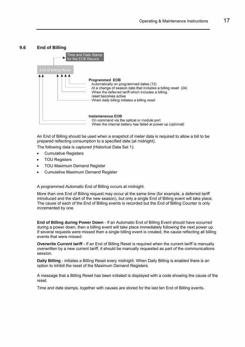
9.6 End of Billing
An End of Billing should be used when a snapshot of meter data is required to allow a bill to be prepared reflecting consumption to a specified date (at midnight). The following data is captured (Historical Data Set 1): • Cumulative Registers • TOU Registers • TOU Maximum Demand Register • Cumulative Maximum Demand Register
A programmed Automatic End of Billing occurs at midnight.
More than one End of Billing request may occur at the same time (for example, a deferred tariff introduced and the start of the new season), but only a single End of Billing event will take place. The cause of each of the End of Billing events is recorded but the End of Billing Counter is only incremented by one.
End of Billing during Power Down - If an Automatic End of Billing Event should have occurred during a power down, then a billing event will take place immediately following the next power up. If several requests were missed then a single billing event is created, the cause reflecting all billing events that were missed.
Overwrite Current tariff - If an End of Billing Reset is required when the current tariff is manually overwritten by a new current tariff, it should be manually requested as part of the communications session. Daily Billing - initiates a Billing Reset every midnight. When Daily Billing is enabled there is an option to inhibit the reset of the Maximum Demand Registers.
A message that a Billing Reset has been initiated is displayed with a code showing the cause of the reset.
Time and date stamps, together with causes are stored for the last ten End of Billing events.

AS230 - AMI Single Phase Meter
© Elster Metering Limited - M200 001 2B - 5.2009
Mon Tue Wed Thu Fri Sat Sun1 2 3 Switching programs
End of Billing Lock-out
Any further End of Billing Resets can be inhibited via the Power Master Unit for either:
- Up to 255 minutes
- Until the end of the hour
- Until the next midnight boundary
Note: This only inhibits instantaneous End of Billing requests either via the pushbutton or communications setting, not programmed End of Billing events.
9.7 Daylight Savings The meter provides 2 Daylight Savings dates whereby the clock can be advanced by one or two hours at the start of the summer and can be retarded by one or two hours at the end of the summer.
The day on which a Daylight Saving occurs is programmable, with the choice of the first, second, third, fourth or last specified weekday in a specified month.
The algorithm used identifies the correct calendar dates for 50 years.
All of the following will reflect Daylight Savings:
• Automatic End of Billing
• Switching times within the tariff definition
• Time and date stamps
• Load profile (optional)
9.8 Independent Day Control The meter has the facility to have a different switching program consisting of several switching times running on different days of the week. An example of a switching program is below:
9.9 Deferred Tariff and Deferred Tariff Changeover Date A second tariff can be programmed in the meter that will take effect from a programmed date.
If an activation date/time before or equal to the current date/time is programmed, the deferred tariff is activated at the next minute boundary.
An option to perform an End of Billing on the Deferred Tariff Changeover Date is available as part of the deferred tariff structure.

Operating & Maintenance Instructions 19
9.10 Tariff/Display Scheme Verification
The meter generates a checksum of the tariff/display scheme currently residing in the meter. The checksum can be included as part of the display sequence, and also compared with a tariff checksum generated by the Power Master Unit. This allows quick verification, either locally or remotely, that the correct tariff/display scheme resides within the meter.
9.11 Historical Data/Daily Billing
9.11.1 Historical Data At each End of Billing the following data is stored to historical registers:
• Cumulative Registers
• TOU Registers
• Maximum Demand Register
There are 12 sets of historical registers.
The oldest set is over written by the new.
9.11.2 Daily Billing
A snapshot of Daily Billing can be provided:
• Cumulative Registers
• TOU Registers
• Maximum Demand Registers
There are 14 sets of Daily Billing registers.
The oldest set is over written by the new.
The snapshot is recorded each midnight. The records can be accessed via the local or module port and is optionally available on the LCD. There is a programmable option to reset the Maximum Demand when the Daily Billing snapshot is taken.
10 INSTRUMENTATION The following Instrumentation Values are measured: • Volts Resolution 0.1V • Current Resolution 0.1A • Active Power Resolution 1W • Reactive Power Resolution 1 var • Apparent Power Resolution 1 VA • Power Factor Resolution 0.001 • Frequency Resolution 0.1Hz Instrumentation Values may be included in the display sequence or read via the local or module port.

AS230 - AMI Single Phase Meter
© Elster Metering Limited - M200 001 2B - 5.2009
11 LOAD/INSTRUMENTATION PROFILE RECORDING
4 Demand Values(kW, kvar, kVA)
Demand Period End
LoadChannels Days 1 120 2 120 4 120
Readings
Optical orModulePorts
InstrumentationChannels Days 4 15 2 35 1 60
Volts, Amps, Active PowerReactive Power, Power Factor, Frequency
30 Minute Periods
The AS230 can be programmed to record up to four load profile values from any of the demand registers at the end of each integration period. A maximum of 120 days of data can be stored for 4 channels with 30 minute intervals. The number of days storage increases if the number of channels is reduced, and decreases if the integration period is reduced.
The number of day's storage will also be affected if Instrumentation Profiling is configured.
11.1 Load Profiling
Four demand values (channels) can be selected from any of the following:
• Import or export kW
• Q1, Q2, Q3 or Q4 kvar
• Import (Q1 +Q2) or Export (Q3 + Q4) kvar
• kVA
11.2 Instrumentation Profiling
The AS230 can be programmed to record up to eight Instrumentation Profile values from any of the quantities specified in Section 10 (Instrumentation). A maximum of 60 days of data can be stored for 8 values with 30 minute intervals. The number of days storage increases if the number of values is reduced, and decreases if the integration period is reduced.
The number of day's storage will also be affected if Load Profiling is configured.

Operating & Maintenance Instructions 21
11.3 Load/Instrumentation Profile Settings
Load Profile and Instrumentation Profile settings are programmed independently and can be set within the following criteria:
Integration period - 1, 2, 3, 4, 5, 6, 10, 15, 20, 30, 60 minutes
Profile data is stored with reference to either base time or daylight saving time.
Base Time - Daylight savings have no effect on the demand period and 48 periods are stored (assuming 30 minute integration period) for each day.
Daylight savings time - On the day when the clock is advanced one hour, 46 periods will be stored. On the day when the clock is retarded 1 hour, 50 periods will be stored (assuming 30 minute integration periods).
Status information is also stored with each integration period record.
Profile event indication with time and date stamps -
Power up Power down Time change Configuration change New day Daylight savings Load (Instrumentation) profile cleared. Profile status indication per period (Load profile only) - Transient reset Time synchronisation Write Access (Data Change) Internal battery failure Reverse run.
Methods of reading profile data
Two methods of reading Profile data are provided: Number of day’s data up to and including the current day From day x up to and including day y.
Profiles can be accessed via the local port or module port.

AS230 - AMI Single Phase Meter
© Elster Metering Limited - M200 001 2B - 5.2009
12 SECURITY FEATURES
12.1 Password Protection
The AS230 meter uses a Password as part of the security algorithm. The passwords must be entered in upper case. Password protection can be disabled on manufacture if required. Four levels of access are available. Entering the correct password for levels 0, 1, 2 and 3 allows the functions in Figure 10 to be performed, higher levels giving access to the lower levels. Passwords may also be set to defaults using the Power Master Unit. A password change event is recorded in a log (last ten events) each time any password is changed. A count of the number of password changes (to a maximum of 65,535) is also recorded. It is important to note that the integrity of the AS230 meter passwords should always be protected. This can be achieved by ensuring the ability to change passwords is controlled and only made available to Administrative Personnel. Calibration values, zeroing of registers etc. are protected by a security link that is removed at the factory before the meter is sealed.
12.2 Data Retention All cumulative registers and time of use data are saved to non-volatile memory once every second.
All data is retained for the nominal life of the meter.
12.3 Recordable Security Features The AS230 records the count and time and date stamp of the last 10 events for each of the recordable security features listed below. The records can be read via the local port or module port. The count and most recent time & date stamp can be included in the display sequence.
12.3.1 Reverse Energy Flow Reverse run event count
The meter detects and stores the number of reverse running events to a maximum of 255. The register will then roll over to 1.
An event is detected if the reverse energy flow exceeds the reverse anti-creep threshold for more than a configured number of seconds (manufacturing option, default value = 5 seconds).
Reverse energy reading
Irrespective of whether the meter is set to import only or to power flow insensitive mode, reverse kWh power flow will be independently recorded.
Reverse energy Alarm (Import only meter)
The reverse run indication on the LCD can be inhibited if required. If the alarm is set, it can be cleared via the local port or module port.
Operating & Maintenance Instructions 23
12.3.2 Power Fail A count of the cumulative number of all power downs (to a maximum of 65,535) is recorded. The register will then roll over to 0.
12.3.3 Long Power Fail Event A count of the cumulative number of power downs (to a maximum of 65,535) with duration above a programmable threshold (0 to 45 days) is recorded (Default 3 minutes).
12.3.4 End of Billing Event A count of the number of end of billing events (to a maximum of 65,535) is recorded. The register will then roll over to 0.
The message ‘Reset’ is displayed each time an End of Billing event takes place.
12.3.5 Programming Event Log A count of the number of programming events (to a maximum of 65,535) is recorded. The identity of the Programming User is also stored for the last 10 events.
Note: Programming events are communications sessions where the meter configuration or data has been changed. Reading data only does not count as a programming event.
12.3.6 Watchdog (Transient Reset) A count of the number of watchdog resets (to a maximum of 65,535) is recorded.
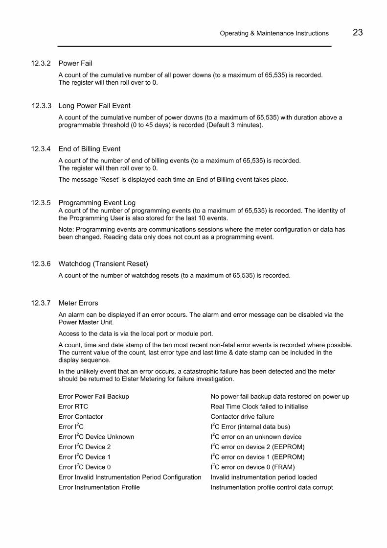
12.3.7 Meter Errors An alarm can be displayed if an error occurs. The alarm and error message can be disabled via the Power Master Unit.
Access to the data is via the local port or module port.
A count, time and date stamp of the ten most recent non-fatal error events is recorded where possible. The current value of the count, last error type and last time & date stamp can be included in the display sequence.
In the unlikely event that an error occurs, a catastrophic failure has been detected and the meter should be returned to Elster Metering for failure investigation. Error Power Fail Backup No power fail backup data restored on power up Error RTC Real Time Clock failed to initialise Error Contactor Contactor drive failure Error I2C I2C Error (internal data bus) Error I2C Device Unknown I2C error on an unknown device Error I2C Device 2 I2C error on device 2 (EEPROM) Error I2C Device 1 I2C error on device 1 (EEPROM) Error I2C Device 0 I2C error on device 0 (FRAM) Error Invalid Instrumentation Period Configuration Invalid instrumentation period loaded Error Instrumentation Profile Instrumentation profile control data corrupt
AS230 - AMI Single Phase Meter
© Elster Metering Limited - M200 001 2B - 5.2009
Error Estimated Battery Life Exceeded Meter powered down for longer than estimated internal battery life Error Invalid Demand Period Configuration Invalid demand period configuration loaded into meter Error Load Profile Load profile data corrupt Error Backup No backup data restored Error Manufacturing Configuration Profiles Error in the load/instrumentation profile configuration Error Manufacturing Configuration Registration Error in the registration configuration
12.3.8 Main Cover Removal Detection As a manufacturing option the main cover can be fitted with a tamper switch to detect removal. A count of the number of times the cover has been removed (to a maximum of 65,535) is recorded.
12.3.9 Terminal Cover Removal Detection As a manufacturing option the terminal cover can be fitted with a tamper switch to detect removal. A count of the number of times the cover has been removed (to a maximum of 65,535) is recorded.
12.3.10 Contactor Remote Reconnect/Disconnect Logs The AS230 monitors all contactor events (see Section 16).
12.3.11 Magnetic Manipulation Detection
The meter has a high degree of immunity against the presence of strong magnetic fields. Magnetic fields above a fixed threshold are detected and a count (to a maximum of 65,535) with time and date stamp is kept of the number of times the level has been exceeded.
12.3.12 Firmware checksum The meter calculates a checksum which can be used to identify the scheme each time new firmware is downloaded.
12.3.13 Firmware download log A count (to a maximum of 65,535) is kept together with time and date stamps and source (local or module).
12.3.14 Battery Voltage Monitoring The voltage on the battery is periodically measured. If the measured voltage indicates the battery is near the end of its useful life, a 'battery fail' flag is set.

Operating & Maintenance Instructions 25
12.3.15 Over-Voltage Events The AS230 records an event log of the last ten over-voltage events if the voltage exceeds a programmable threshold. The cumulative count (to a maximum of 65,535) of the most recent over-voltage and under-voltage events can be included in the display sequence together with time and date stamps.
12.3.16 Under-Voltage Events The AS230 records an event log of the last ten under-voltage events if the voltage falls below a programmable threshold. The cumulative count (to a maximum of 65,535) of the most recent over-voltage and under-voltage events can be included in the display sequence together with time and date stamps.
12.4 Additional Security Features
12.4.1 In Service Hours The elapsed time counter records the cumulative time (to a resolution of 1 hour) the meter has been powered up.
The maximum value of this counter represents more than 25 years.
12.4.2 Remaining Internal Battery Life The AS230 provides a count of the number of hours of life left in the battery. The remaining battery life can be included in the display sequence.
The count is calculated by subtracting the amount of time the meter has been supported during power outages from the initial battery life estimate. When this value reaches zero a 'predicted battery life exceeded' flag is set.

AS230 - AMI Single Phase Meter
© Elster Metering Limited - M200 001 2B - 5.2009
13 METER DISPLAY
13.1 Introduction
The meter is fitted with a high contrast liquid crystal display that can be viewed from a wide angle. The main display characters are 9.8mm high. The display can be configured at manufacture to display English descriptors or chevrons.
The Test Display with a description of the displayed legend is shown below.
The display can be configured using the Power Master Unit to display data with English descriptors or OBIS (Object Identification System) descriptors.
13.2 General
Display Resolution The resolution of the display can be set at manufacture to 7, 6 or 5 digits. The decimal point indicator can be configured to be a point or a comma and set to 0, 1 or 2 places. kWh Wh mWh
Internal storage is :- 1 2 3 4 5 6 7 8 9 0 1 2 3. 4 5 6 The display is a window of this. e.g. 1 2 3 4 5 6 7 8 9 0 1 2 3. 4 5 6
Seven Digits Six Digits Five Digits 4 5 6 7 8 9 0 5 6 7 8 9 0. 1 6 7 8 9 0. 1 2
5 6 7 8 9 0 6 7 8 9 0. 1 7 8 9 0. 1 2
6 7 8 9 0 7 8 9 0. 1 8 9 0. 1 2

Operating & Maintenance Instructions 27
Units of Quantity The Units of Quantity (m3, V, A, kW, kWh, kVA, kVAh, kVAr, kVArh, £, €) displayed are selectable by the Power Master Unit and displayed in the top right corner of the display.
13.3 Display Modes
The display has three modes of operation, Auto-cycle mode, Manual Mode and Utility Mode.
Up to 256 displays can be displayed in total for the three modes of operation. Figure 7A illustrates the 3 display modes.
13.3.1 Auto-cycle Mode At power up the segment test pattern is shown. This will remain displayed for the dwell time.
The display will then sequence through the programmed displays, remaining on each display item for one-step duration, called the dwell time (2-30 seconds).
Dwell time (2 - 30 seconds)
Dwell time
Dwell time
Dwell time
Next display
Last display
First display in auto-cycle sequence

AS230 - AMI Single Phase Meter
© Elster Metering Limited - M200 001 2B - 5.2009
13.3.2 Manual Mode Manual mode is entered by a single short press of the Display Pushbutton. This causes "Step" to be displayed. Further short presses of the pushbutton allow the consumer to step through the configured Manual Mode display items.
The display will return to auto-cycle mode at a programmed time after the last press of the display pushbutton.
Button press
Button press
Button press
Autocycle Mode
No pushbutton pressreturns to start ofautocycle mode
Button press
Button press
Last display
13.3.3 Utility Mode
The Utility mode is entered from Manual mode by a long press of the Pushbutton. ‘Utility’ appears on the display.
Single short presses of the pushbutton will then step through the utility displays.
The display will default to auto-cycle mode at a programmed time after the last press of the Pushbutton, or after a long press of the pushbutton.
First display in step mode

Operating & Maintenance Instructions 29
Button press
Button press
Long button press(From Manual Mode)
No pushbutton pressor long pushbutton press
returns to start ofautocycle display
sequence
Button press
Button press
Last display
13.3.4 English Display
Descriptors & Identifiers
The Display Descriptors and Identifiers have the following meaning: Identifiers
Descriptors
Import/Export
The display identifiers give a description of the main register displayed.
Examples of the display are shown in Figures 7.
A list of displays is given in Figure 8.
13.3.5 OBIS Display
The OBIS code gives a description of the main register displayed. OBIS Code
The display shows active energy T1. The Time of use register is currently active.
Identifiers/Descriptors Identifiers Register Number
Active Register displayed is currently active TOU Time of Use Register CUM Cumulative Register
MAX DEM Maximum Demand Register CUM MAX DEM Cumulative Max Demand register
DEM Demand Register I Import
First display in Utility sequence

AS230 - AMI Single Phase Meter
© Elster Metering Limited - M200 001 2B - 5.2009
13.4 Displayable Data
A full list of displayable data items is given in Figure 8. Items available will depend on the meter variant. The main categories are shown below: • Segment Test • Cumulative Registers • TOU Registers • Maximum Demand • Most Recent Set of Billing Registers • Security • Instrumentation • Tariff Display checksum • Metrological firmware checksum • Meter Errors
13.5 Dial Test
For dial testing, the cumulative kWh and kvarh displays can be temporarily set to a higher resolution using the Power Master Unit.
The resolution of the display is set to show 2 decimal places.
The meter will cease using dial test resolution when instructed by the Power Master Unit.
13.6 Display Indicators
Reverse Run Indication
Meter Error Alarm
Energy Direction Indicators
Communications Indication When communications are taking place the following indicators are displayed.
o Local communication
r Remote communications
HAN (Home Area Network) communications
WAN (Wide Area Network) communications

Operating & Maintenance Instructions 31
Contactor
Contactor Open
Contactor Armed Ready for Closing (Flashes)
Contactor Closed (No Indication)
14 USING THE PUSHBUTTON The pushbutton is used to:
• Step through the data on the display
• Close the contactor (once it has been armed for closure)
• Enable a read during power outages (Optional)
• Initiate the self registration process
Stepping the display
Defaults Display Mode - A short press of the pushbutton enters manual display mode. This causes "StEP" to be displayed. Further short presses of the display pushbutton allow the user to step through the manual display sequence. The display will return to auto-cycle mode at a programmed time after the last press of the pushbutton.
Utility Display Mode - From manual display mode a long press of the pushbutton enters the utility display mode and "UtILItY" is displayed. Short presses of the pushbutton allow the user to step through the utility display sequence. The display will return to auto-cycle mode at a programmed time after the last press of the display pushbutton or after a long press of the pushbutton.
Contactor Closing - If the Main contactor is open, it can be set to an 'Armed' state using a command via the local or module ports.
The contactor can then be closed by pressing the pushbutton for the "Long button press" duration.
Initiating the Self-registration Process - When self-registration has been programmed to be shown in the Utility Display the module self-registration process can be initiated by:
- Stepping to the display
- A long button press
Long/Short Presses - The duration of the long button press is set at manufacture between one and fifteen seconds. Any pushbutton press less than the long press duration constitutes a short pushbutton press.

AS230 - AMI Single Phase Meter
© Elster Metering Limited - M200 001 2B - 5.2009
15 COMMUNICATIONS
Communications with the meter can be established locally using the optical port or remotely via the module port. A symbol can be displayed which gives an indication of the type of communications (local, WAN or HAN) currently taking place.
15.1 Local Communications Port A bi-directional infra red communications port (IEC 62056-21) is provided to allow reading of all stored data (measurement, diagnostic and current personality) and programming of "personality" data.
The port is accessible through the front of the main cover and interfaces to a hand held unit or computer. In normal operation the port only operates when the meter is powered from the a.c. supply.
The port can operate at baud rates of up to 9600.
15.2 Module Communications
A module that supports WAN (LAN) and /or HAN communications can be installed in the module housing.
Module communications can be GSM, GPRS, PLC, RF etc. HAN can be wired or RF (e.g. Wavenis).
See Chapter 3 (Communications) for module description and installation.
15.2.1 WAN/HAN Signal Strength Signal strength values can be displayed for the WAN and the HAN communication channels. The values are initialised to zero each time the meter is powered up.
Operating & Maintenance Instructions 33
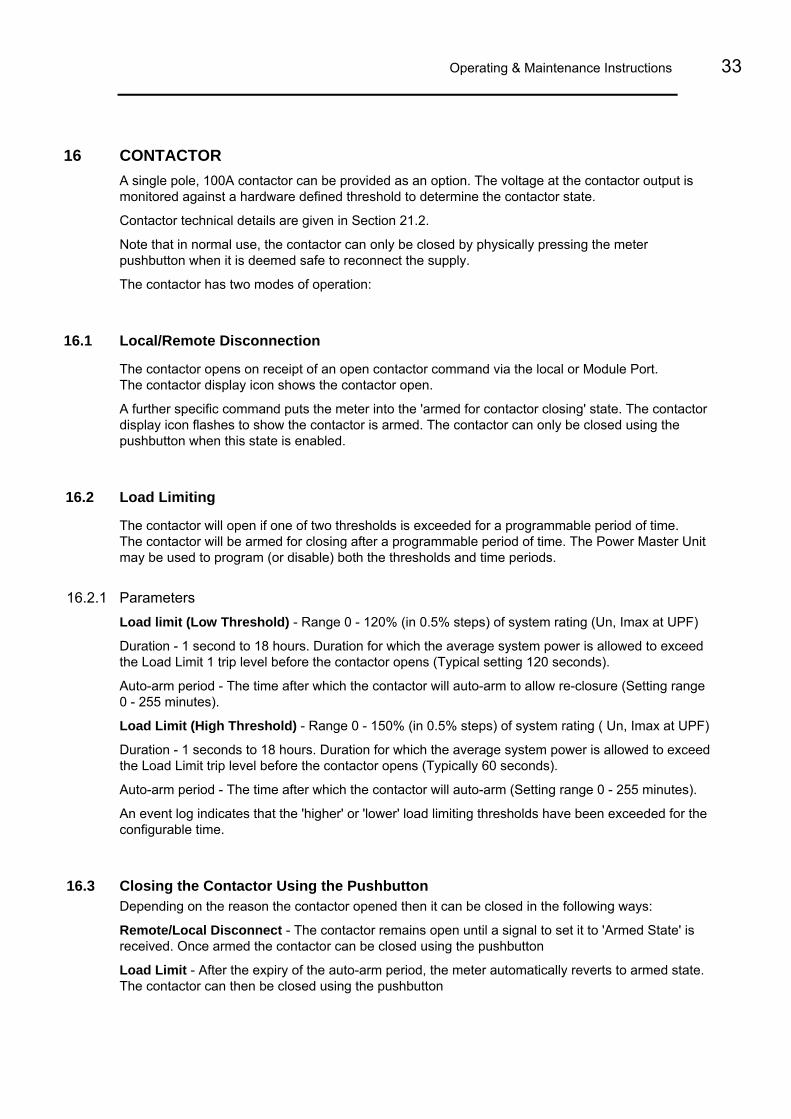
16 CONTACTOR A single pole, 100A contactor can be provided as an option. The voltage at the contactor output is monitored against a hardware defined threshold to determine the contactor state.
Contactor technical details are given in Section 21.2.
Note that in normal use, the contactor can only be closed by physically pressing the meter pushbutton when it is deemed safe to reconnect the supply.
The contactor has two modes of operation:
16.1 Local/Remote Disconnection
The contactor opens on receipt of an open contactor command via the local or Module Port. The contactor display icon shows the contactor open.
A further specific command puts the meter into the 'armed for contactor closing' state. The contactor display icon flashes to show the contactor is armed. The contactor can only be closed using the pushbutton when this state is enabled.
16.2 Load Limiting
The contactor will open if one of two thresholds is exceeded for a programmable period of time. The contactor will be armed for closing after a programmable period of time. The Power Master Unit may be used to program (or disable) both the thresholds and time periods.
16.2.1 Parameters Load limit (Low Threshold) - Range 0 - 120% (in 0.5% steps) of system rating (Un, Imax at UPF)
Duration - 1 second to 18 hours. Duration for which the average system power is allowed to exceed the Load Limit 1 trip level before the contactor opens (Typical setting 120 seconds).
Auto-arm period - The time after which the contactor will auto-arm to allow re-closure (Setting range 0 - 255 minutes).
Load Limit (High Threshold) - Range 0 - 150% (in 0.5% steps) of system rating ( Un, Imax at UPF)
Duration - 1 seconds to 18 hours. Duration for which the average system power is allowed to exceed the Load Limit trip level before the contactor opens (Typically 60 seconds).
Auto-arm period - The time after which the contactor will auto-arm (Setting range 0 - 255 minutes).
An event log indicates that the 'higher' or 'lower' load limiting thresholds have been exceeded for the configurable time.
16.3 Closing the Contactor Using the Pushbutton Depending on the reason the contactor opened then it can be closed in the following ways:
Remote/Local Disconnect - The contactor remains open until a signal to set it to 'Armed State' is received. Once armed the contactor can be closed using the pushbutton
Load Limit - After the expiry of the auto-arm period, the meter automatically reverts to armed state. The contactor can then be closed using the pushbutton

AS230 - AMI Single Phase Meter
© Elster Metering Limited - M200 001 2B - 5.2009
16.4 Closing the Contactor by Remote Control On specific occasions it may be necessary to close the contactor when nobody is present to check that this will be safe - that no heating loads, electric kettles etc have been left switched on. For these situations, the contactor may be closed using a specific remote command, but a Safety Re-disconnect function will provide additional protection.
The contactor must have been set to the 'armed for closure' state prior to sending the closure command.
Whenever the contactor is closed using the remote command, the current flowing through the meter is monitored against a programmed current threshold for a programmed period of time. If current flow rises above the programmed threshold the contactor will automatically re-open.
If the contactor opens because the current threshold has been exceeded, the meter will either:
1. Remain in the 'contactor open, not re-armed' state
2. After a configurable period of time, go back into the 'armed for closure' state
For safety reasons it is advisable to set the current threshold to the lowest suitable value.
The Safety Re-disconnect function does not operate when the pushbutton is used to close the contactor.
16.5 Power Outages If the contactor is 'armed' it will remain in the armed state during power outages. Once power is restored the contactor can be closed using the pushbutton, or remote command.
16.6 Event Logs The last 10 events together with count, time/date stamp and success or failure record are recorded for the following events:
• Contactor opened via the optical communications channel
• Contactor opened via the module communications channel
• Contactor opened via the load monitoring 'lower' threshold exceeded
• Contactor opened via the load monitoring 'higher' threshold exceeded
• Contactor armed via the optical communications channel
• Contactor armed via the module communications channel
• Contactor opened via a load monitoring auto arm request
• Contactor closed via the optical communications channel
• Contactor closed via the module communications channel
• Contactor closed via the pushbutton

Operating & Maintenance Instructions 35
17 PROGRAMMING THE METER
The meter can be programmed via the optical (local) or module port. The local port can be connected either directly to a PC (IBM compatible) or to a Hand Held Unit. In both cases an IEC 62056-21 probe is required.
Information for the meter is first prepared on forms within the Power Master Unit Software (Refer to Master Unit Software M200 001 4) and then transferred to the meter.
The meter does not check to ensure that reprogramming has been completed, therefore at the end of a reprogramming session all data should be read back to confirm the meter is programmed correctly.
If communications fail during programming a failure message is displayed.
Each time the meter is reprogrammed, the programming counter is incremented and the time and date of the event is recorded. The 'User Id' of the user who created the scheme in the PMU is recorded in the meter.
Note: The programming counter does not increment when only a 'Set time' or 'Time and date adjustment' is programmed to the meter.
18 REAL TIME CLOCK AND CALENDAR The clock uses the notation 00:00 to 23:59. The calendar automatically caters for leap years.
Note: - For time stamps 00:00 indicates the start of the day and 24:00 the end of the day.
The time base for the clock is a programmable option. It can be derived from either the a.c. supply frequency or from a crystal controlled oscillator.
When the clock is synchronised to the mains frequency, it maintains synchronisation for variations of up to +/- 5% of nominal mains frequency. Outside these limits the meter switches to the crystal oscillator and then reverts back to mains when the frequency is again within limits.
Crystal calibration achieves an internal accuracy of better than 0.5 of a second per day at reference temperature. In the event of a supply failure a backup battery supports the crystal oscillator, which maintains timekeeping.
There are two methods of adjusting the meter clock:
1. The time and date of the clock may be set via the local or module port provided the correct (level 2 or higher) password is used.
2. If a request for a small adjustment (-7.5 minutes to +7.5 minutes) to the current setting is made (with appropriate password), this adjustment will be applied by shortening or lengthening subsequent demand periods by 5 seconds until the whole of the adjustment has been achieved.
19 BATTERY BACK-UP
19.1 Internal Battery
The meter has an internal battery that supports the clock and calendar during power outages.
The meter can be programmed to initiate one of the following courses of action should the supply fail and the battery become exhausted. When the supply returns: - a. Freeze the TOU registers and increment the total cumulative registers only b. Assume the last known time and continue to use the TOU registers
See Section 25 for battery disposal.

AS230 - AMI Single Phase Meter
© Elster Metering Limited - M200 001 2B - 5.2009
19.1.1 Internal Battery Monitoring
The battery provides support for the life of the meter. The following functions are provided on the Battery Monitor: -
Elapsed Time - The total amount of battery support time is monitored. The Elapsed Time Counter increments during power outages
Remaining Time - The remaining battery life is calculated by subtracting the elapsed time from the expected battery life. The remaining life may be read via the local or module port and its value included in the display sequence (optional)
If the remaining time falls to zero, a ‘flag’ is set which can be read via the local or module port
Battery Measurement - The meter initiates an internal battery measurement once per day and each time the meter is powered up. The meter holds the measured value until the next measurement is made
Battery Low Warning - An event log is generated if the battery voltage falls below a predetermine threshold. The last 10 events are recorded which include count and time and date stamp
Battery Failure- If the measured voltage falls below the failure threshold the ERR_RTC flag is set. The Meter alarm (if configured) is shown on the display. Depending on how the meter has been configured to react to the battery failure, further messages may be shown on the display

Operating & Maintenance Instructions 37
20 AUXILIARY OUTPUT
20.1 SO Output (Optional)
An SO pulsed output can be provided as an option. The SO output is driven in parallel with the Meter kWh Test LED.
SO pulse width: 40 ms (mimics Test LED)
SO pulse Rate: As LED pulse rate shown on meter nameplate (See Section 21)
Output Transistor Rating: 27V d.c.
The output is connected to the meter's two auxiliary terminals and is fully isolated.
20.2 Relay Output (Optional)
As an alternative to the SO Output, the meter may be built with a 100mA, mains rated relay output.
A number of the TOU or Maximum Demand Registers are identified in the "Relay Configuration" setting. The relay will be turned 'on' if any one or more of these registers are active. The relay will be 'off' if none of the registers are active.
AS230 - AMI Single Phase Meter
© Elster Metering Limited - M200 001 2B - 5.2009
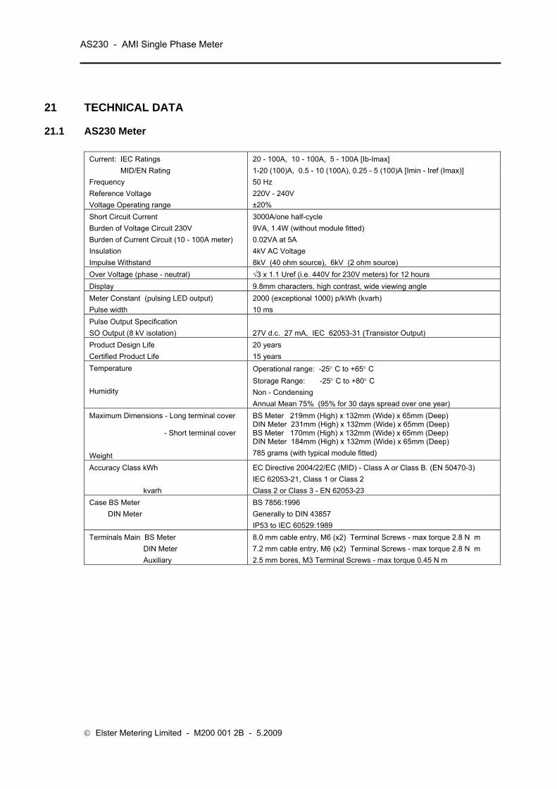
21 TECHNICAL DATA
21.1 AS230 Meter
Current: IEC Ratings MID/EN Rating
20 - 100A, 10 - 100A, 5 - 100A [Ib-Imax] 1-20 (100)A, 0.5 - 10 (100A), 0.25 - 5 (100)A [Imin - Iref (Imax)]
Frequency Reference Voltage Voltage Operating range
50 Hz 220V - 240V ±20%
Short Circuit Current Burden of Voltage Circuit 230V Burden of Current Circuit (10 - 100A meter) Insulation Impulse Withstand
3000A/one half-cycle 9VA, 1.4W (without module fitted) 0.02VA at 5A 4kV AC Voltage 8kV (40 ohm source), 6kV (2 ohm source)
Over Voltage (phase - neutral) √3 x 1.1 Uref (i.e. 440V for 230V meters) for 12 hours Display 9.8mm characters, high contrast, wide viewing angle Meter Constant (pulsing LED output) Pulse width
2000 (exceptional 1000) p/kWh (kvarh) 10 ms
Pulse Output Specification SO Output (8 kV isolation)
27V d.c. 27 mA, IEC 62053-31 (Transistor Output)
Product Design Life Certified Product Life
20 years 15 years
Temperature Humidity
Operational range: -25° C to +65° C Storage Range: -25° C to +80° C Non - Condensing Annual Mean 75% (95% for 30 days spread over one year)
Maximum Dimensions - Long terminal cover - Short terminal cover Weight
BS Meter 219mm (High) x 132mm (Wide) x 65mm (Deep) DIN Meter 231mm (High) x 132mm (Wide) x 65mm (Deep) BS Meter 170mm (High) x 132mm (Wide) x 65mm (Deep) DIN Meter 184mm (High) x 132mm (Wide) x 65mm (Deep) 785 grams (with typical module fitted)
Accuracy Class kWh kvarh
EC Directive 2004/22/EC (MID) - Class A or Class B. (EN 50470-3) IEC 62053-21, Class 1 or Class 2 Class 2 or Class 3 - EN 62053-23
Case BS Meter DIN Meter
BS 7856:1996 Generally to DIN 43857 IP53 to IEC 60529:1989
Terminals Main BS Meter DIN Meter Auxiliary
8.0 mm cable entry, M6 (x2) Terminal Screws - max torque 2.8 N m 7.2 mm cable entry, M6 (x2) Terminal Screws - max torque 2.8 N m 2.5 mm bores, M3 Terminal Screws - max torque 0.45 N m

Operating & Maintenance Instructions 39
21.2 Contactor Technical Data
Contact Data Max Contact Arrangement Contact Material Maximum Switching Power Maximum Switching Voltage Maximum Switching Current Mechanical Life
1 A/ NO / T AgSnO2
28,000 VA 440 VAC 120A 106 operations
Standards Design and Manufacture Short Circuit withstand
DIN IEC 61810, Part 1-00/VDE 0435, Part 201 (Also in accordance to the Low Voltage Directive) DIN EN 61036/037/038 and IEC 62055
General Data Ambient Temperature Conform To
-25... +80 ْ C VDE, UL, CSA, SEV, SEMKO

AS230 - AMI Single Phase Meter
© Elster Metering Limited - M200 001 2B - 5.2009
22 INSTALLATION
22.1 Unpacking
Remove the meter from its packaging and inspect for damage.
Check that there is no movement or loose parts within the meter enclosure.
If damage has been sustained in transit, an immediate claim should be made to the Transport Company, and a report sent to the Elster Metering Systems branch office or agent.
WARNING
Removal of the main cover seals will invalidate certification.
The meter type and rating must be correct for the intended application.
22.2 Handling Once removed from the packaging, meters must be treated with care and not subjected to excessive shock or mechanical vibration.
Care should be taken to avoid marking or scratching the meter case and polycarbonate cover.
22.3 Storage If the meter is not required for immediate use, it should be returned to the original packing (including plastic bag) and stored in a clean, dry environment. Storage temperature: -25° C to + 80° C
22.4 Installation Site The installation site should be a dry indoor environment and, as far as is practicable, away from direct sunlight and free from mechanical shock and vibration.
22.5 Electromagnetic Compatibility (EMC) The AS230 meter has been designed and tested for compliance with the EMC Directive.
It is, however, the responsibility of the installer for ensuring that a system conforms to the Directive.

Operating & Maintenance Instructions 41
In order to assist the installer the following guidelines are given: - 1. Keep a.c. circuits and d.c. circuits separated by a minimum of 50mm where possible 2. Where a.c. and d.c. circuits must cross, do so at right angles to each other 3. The cables for each circuit must be bunched together to minimise the loop area enclosed 4. The cables for the pulsing output must use a twisted pair. Where the environment is electrically
hostile, screened twisted pair cable may be required. The screen must be connected to earth at one point only
5. Ancillary equipment must also be CE marked 6. If interposing relays are used (a.c. or d.c.) then these must be correctly and adequately
suppressed
22.6 Fixing and Connection WARNING
Installation must always be carried out by appropriately trained and qualified personnel in accordance with normal metering custom and practice.
The installer is responsible for the choice of connecting cables which must be appropriate for the voltage and current rating of the meter and for ensuring that the supply is properly fused. Meters must be protected by fuses equal to the meter rating. i.e. 100A fuse for a 100A meter. Failure to do so may result in damage or fire.
Refer to the connection diagrams inside the terminal cover, paying particular attention to the auxiliary terminal configuration.
Mains circuits connected to the relay option auxiliary terminals must be protected by appropriately rated fuses.
Isolate all circuits before carrying out the installation.
Refer to the nameplate to ensure that the correct meter is being installed. Failure to comply with these instructions may result in damage, fire and/or electric shock.
To mount the meter on the meter board Remove the meter terminal cover.
Fix a 5mm dia. x 13mm long round headed wood screw into the meter board to accommodate the keyhole fixing aperture at the back of the meter. Leave the shank of the screw projecting from the board by 4.5 mm.
Note: For DIN meters the top fixing can be exposed or hidden behind the meter base. Choose the required keyhole fixing aperture. Hang the meter on the screw and align it to be vertical. Secure the lower end of the meter to the board using two 5mm dia. x 13mm long round head screws through the lower mounting holes in the area of the terminal chamber. Tighten screws just sufficiently to prevent movement of the meter.
AS230 - AMI Single Phase Meter
© Elster Metering Limited - M200 001 2B - 5.2009
WARNING
Do not over-tighten the screws or the meter base may be damaged. For connecting to the large diameter terminals, strip back the cable insulation by 26mm.
Fully insert cables into the terminals so that the insulation butts up into the counter-sunk recesses in the bottom face of the terminal block.
Using a Number 2 Pozidriv or flat blade screwdriver, tighten the M6 terminal screws to a torque of between 2.2N m (minimum), 2.8N m (maximum).
Auxiliary terminal connections should be completed with appropriately sized cable.
23 COMMISSIONING
WARNING
Commissioning must only be carried out by appropriately trained and qualified personnel.
Check that the supply rating on the meter nameplate corresponds to the system rating.
Removal of the meter cover seals will invalidate certification.
With the system de-energised, check the cable connections are secure and correct to the wiring diagram fitted under the terminal cover
Refit and seal the terminal cover. Energise and load the system
At power-up, ensure all segments of the LCD show in the test pattern
Check that the display is cycling through the display sequence
Check that the LED test indicator(s) are illuminated or flashing
Check the operation of the pulse output (if fitted)
Check operation of the optical communications port and module port
Carry out load checks as necessary
Operating & Maintenance Instructions 43
24 MAINTENANCE No maintenance is necessary during the meter's normal working life.
25 DISPOSAL AND RECYCLING Liquid Crystal Display Liquid crystals are toxic. If a display is damaged, avoid contact with the liquid. If the liquid makes contact with the skin it must be washed off immediately with water. Seek medical advice.
Recycling Materials The following meter materials are recyclable: polycarbonates, metals and printed circuit board (See Safety Warning in Section 2).
Major plastic parts are marked with recycling information. On the disposal of a meter, every endeavour should be made to comply with local environmental legislation regarding recovering materials and waste disposal.
Batteries
If the main cover is removed from the meter then a Lithium manganese dioxide battery will be exposed.
This battery is completely safe under normal conditions. However, it must never be disassembled, heated above 100°C, incinerated, nor have the contents exposed to water.
Fire, explosion or severe burns may result if these instructions are disregarded.
In the interests of safety, environmental protection and possible legislation, Lithium batteries require careful disposal.
Before arranging for the disposal of these cells, users should satisfy themselves that the proposed means of disposal is both safe and compliant with local legislation requirements.
Elster Metering Systems would like to draw the user's attention to the International Standard for Lithium Batteries - IEC 60084-4 - which gives further information about the handling, storage, transport and disposal of Lithium cells.
The user should contact Elster Metering Systems should difficulties arise in arranging proper disposal. They will if practical, help the user identify safe disposal means.
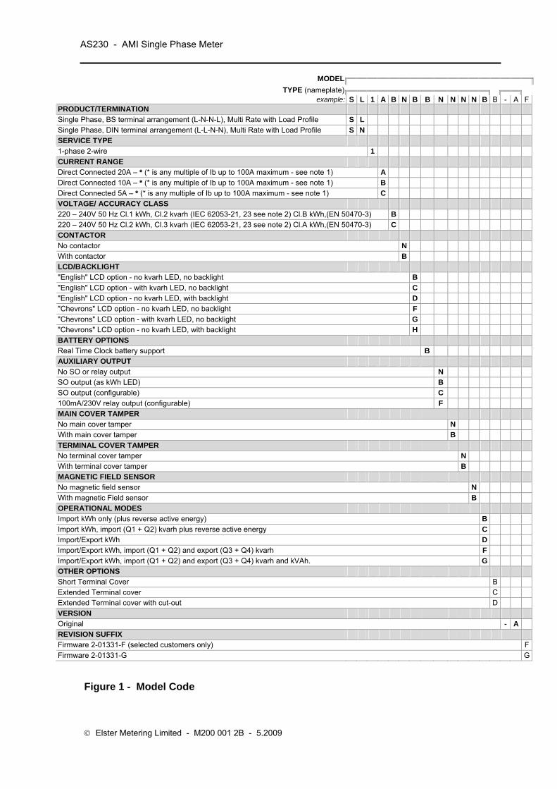
AS230 - AMI Single Phase Meter
© Elster Metering Limited - M200 001 2B - 5.2009
MODEL
TYPE (nameplate)
example: S L 1 A B N B B N N N N B B - A FPRODUCT/TERMINATION Single Phase, BS terminal arrangement (L-N-N-L), Multi Rate with Load Profile S L Single Phase, DIN terminal arrangement (L-L-N-N), Multi Rate with Load Profile S N SERVICE TYPE 1-phase 2-wire 1 CURRENT RANGE Direct Connected 20A – * (* is any multiple of Ib up to 100A maximum - see note 1) A Direct Connected 10A – * (* is any multiple of Ib up to 100A maximum - see note 1) B Direct Connected 5A – * (* is any multiple of Ib up to 100A maximum - see note 1) C VOLTAGE/ ACCURACY CLASS 220 – 240V 50 Hz Cl.1 kWh, Cl.2 kvarh (IEC 62053-21, 23 see note 2) Cl.B kWh,(EN 50470-3) B 220 – 240V 50 Hz Cl.2 kWh, Cl.3 kvarh (IEC 62053-21, 23 see note 2) Cl.A kWh,(EN 50470-3) C CONTACTOR No contactor N With contactor B LCD/BACKLIGHT "English" LCD option - no kvarh LED, no backlight B "English" LCD option - with kvarh LED, no backlight C "English" LCD option - no kvarh LED, with backlight D "Chevrons" LCD option - no kvarh LED, no backlight F "Chevrons" LCD option - with kvarh LED, no backlight G "Chevrons" LCD option - no kvarh LED, with backlight H BATTERY OPTIONS Real Time Clock battery support B AUXILIARY OUTPUT No SO or relay output N SO output (as kWh LED) B SO output (configurable) C 100mA/230V relay output (configurable) F MAIN COVER TAMPER No main cover tamper N With main cover tamper B TERMINAL COVER TAMPER No terminal cover tamper N With terminal cover tamper B MAGNETIC FIELD SENSOR No magnetic field sensor N With magnetic Field sensor B OPERATIONAL MODES Import kWh only (plus reverse active energy) B Import kWh, import (Q1 + Q2) kvarh plus reverse active energy C Import/Export kWh D Import/Export kWh, import (Q1 + Q2) and export (Q3 + Q4) kvarh F Import/Export kWh, import (Q1 + Q2) and export (Q3 + Q4) kvarh and kVAh. G OTHER OPTIONS Short Terminal Cover B Extended Terminal cover C Extended Terminal cover with cut-out D VERSION Original - A REVISION SUFFIX Firmware 2-01331-F (selected customers only) FFirmware 2-01331-G G
Figure 1 - Model Code
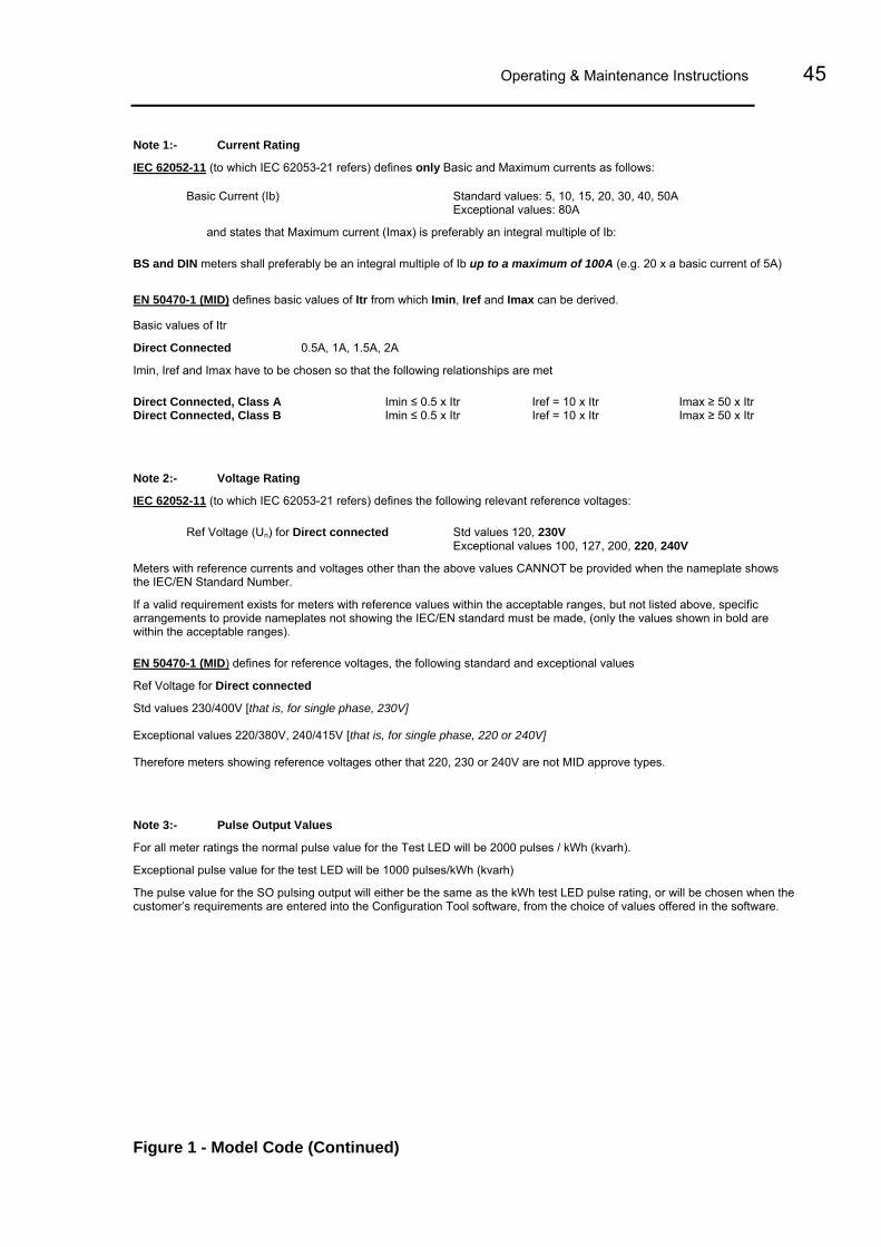
Operating & Maintenance Instructions 45
Note 1:- Current Rating
IEC 62052-11 (to which IEC 62053-21 refers) defines only Basic and Maximum currents as follows:
Basic Current (Ib) Standard values: 5, 10, 15, 20, 30, 40, 50A Exceptional values: 80A
and states that Maximum current (Imax) is preferably an integral multiple of Ib:
BS and DIN meters shall preferably be an integral multiple of Ib up to a maximum of 100A (e.g. 20 x a basic current of 5A) EN 50470-1 (MID) defines basic values of Itr from which Imin, Iref and Imax can be derived.
Basic values of Itr
Direct Connected 0.5A, 1A, 1.5A, 2A
Imin, Iref and Imax have to be chosen so that the following relationships are met
Direct Connected, Class A Imin ≤ 0.5 x Itr Iref = 10 x Itr Imax ≥ 50 x Itr Direct Connected, Class B Imin ≤ 0.5 x Itr Iref = 10 x Itr Imax ≥ 50 x Itr
Note 2:- Voltage Rating
IEC 62052-11 (to which IEC 62053-21 refers) defines the following relevant reference voltages:
Ref Voltage (Un) for Direct connected Std values 120, 230V Exceptional values 100, 127, 200, 220, 240V
Meters with reference currents and voltages other than the above values CANNOT be provided when the nameplate shows the IEC/EN Standard Number.
If a valid requirement exists for meters with reference values within the acceptable ranges, but not listed above, specific arrangements to provide nameplates not showing the IEC/EN standard must be made, (only the values shown in bold are within the acceptable ranges).
EN 50470-1 (MID) defines for reference voltages, the following standard and exceptional values
Ref Voltage for Direct connected
Std values 230/400V [that is, for single phase, 230V]
Exceptional values 220/380V, 240/415V [that is, for single phase, 220 or 240V]
Therefore meters showing reference voltages other that 220, 230 or 240V are not MID approve types.
Note 3:- Pulse Output Values
For all meter ratings the normal pulse value for the Test LED will be 2000 pulses / kWh (kvarh).
Exceptional pulse value for the test LED will be 1000 pulses/kWh (kvarh)
The pulse value for the SO pulsing output will either be the same as the kWh test LED pulse rating, or will be chosen when the customer’s requirements are entered into the Configuration Tool software, from the choice of values offered in the software.
Figure 1 - Model Code (Continued)

AS230 - AMI Single Phase Meter
© Elster Metering Limited - M200 001 2B - 5.2009
Figure 2 – BS AS230 with Module Fitted (Long Terminal Cover)

Operating & Maintenance Instructions 47
Mains connector
The module slides into the module housing.
Figure 2A – Meter Module Housing
12 pin data connector

AS230 - AMI Single Phase Meter
© Elster Metering Limited - M200 001 2B - 5.2009
Figure 3 - Typical Nameplate
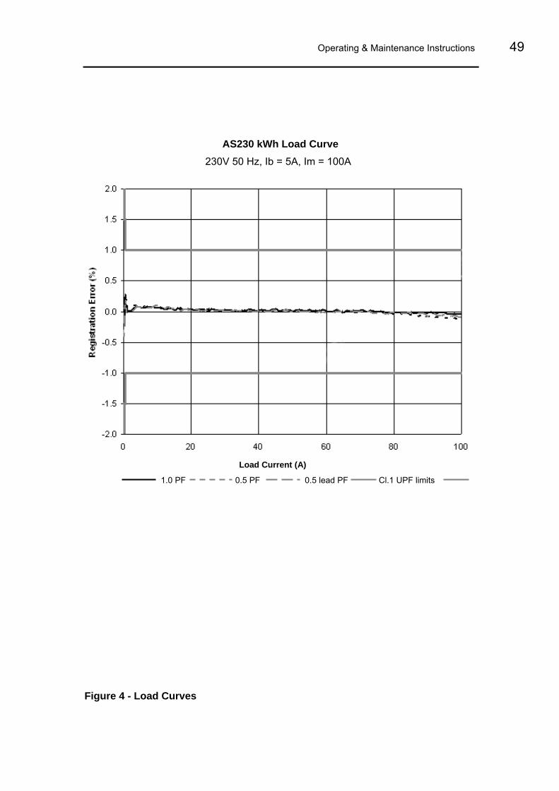
Operating & Maintenance Instructions 49
AS230 kWh Load Curve 230V 50 Hz, Ib = 5A, Im = 100A
Load Current (A)
1.0 PF 0.5 PF 0.5 lead PF Cl.1 UPF limits
Figure 4 - Load Curves
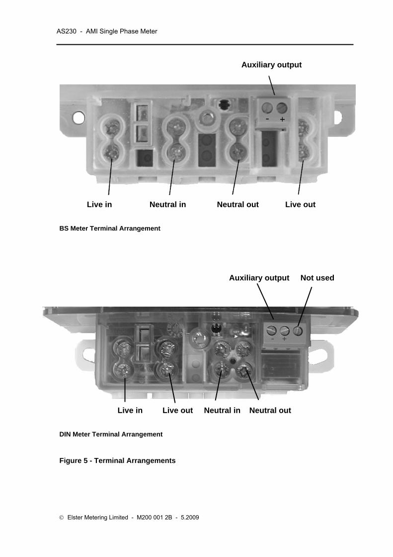
AS230 - AMI Single Phase Meter
© Elster Metering Limited - M200 001 2B - 5.2009
Auxiliary output
Live in Neutral in Neutral out Live out
BS Meter Terminal Arrangement
Auxiliary output Not used
Live in Live out Neutral in Neutral out
DIN Meter Terminal Arrangement
Figure 5 - Terminal Arrangements

Operating & Maintenance Instructions 51
BS without auxiliary connection BS with relay output option
DIN with relay output option
Note: These diagrams are examples only.
WARNING
Meters must be connected according to the diagram fitted under the meter terminal cover.
Figure 5A – Terminal Configurations

AS230 - AMI Single Phase Meter
© Elster Metering Limited - M200 001 2B - 5.2009
170mm(219mm withlong terminal
cover)
132.0mm 65.2mm
105mm
132.4mm
Long Terminal Cover
Short Terminal Cover
Figure 6 – Dimensions and Fixing Centres (BS)

Operating & Maintenance Instructions 53
Figure 6A – Dimensions and Fixing Centres (DIN)

AS230 - AMI Single Phase Meter
© Elster Metering Limited - M200 001 2B - 5.2009
English Displays OBIS Displays
Test Display
Time Current Time
Date Current Date
kWh (Rate 2) kWh Cumulative Import
Maximum Demand Cumulative Maximum Demand
Max Demand Date Max Demand Time
Units of Quantity
kW, kWh kVA, kVAh kVAr, kVArh m3, V, A, £, €
Figure 7 - Displays
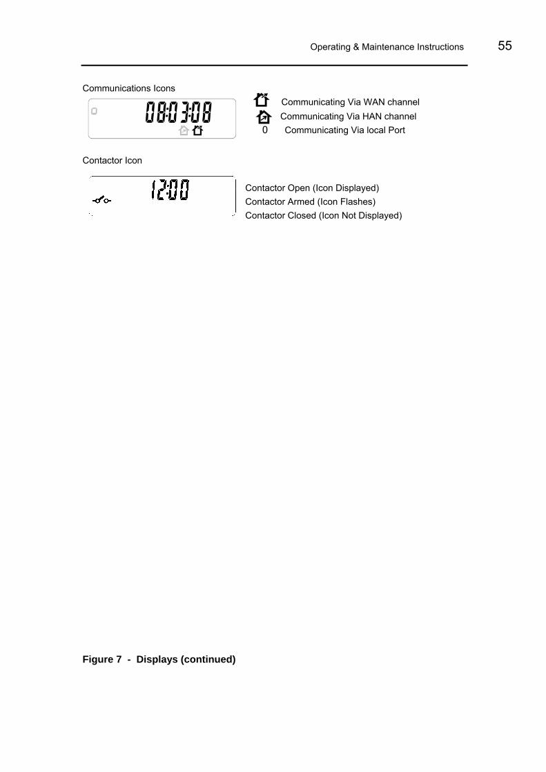
Operating & Maintenance Instructions 55
Communications Icons Communicating Via WAN channel Communicating Via HAN channel
0 Communicating Via local Port
Contactor Icon
Contactor Open (Icon Displayed) Contactor Armed (Icon Flashes) Contactor Closed (Icon Not Displayed)
Figure 7 - Displays (continued)

AS230 - AMI Single Phase Meter
© Elster Metering Limited - M200 001 2B - 5.2009
Figure 7A Display Modes

Operating & Maintenance Instructions 57
Group Display Identifiers Units OBIS Identifier
Index General Current Time 0.9.1
Current Date 0.9.2
Cumulative Import Wh kWh 1.8.0 CUM I
Cumulative Export Wh kWh 2.8.0 CUM E
Cumulative Q1 varh kvarh 5.8.0 CUM └1
Cumulative Q2 varh kvarh 6.8.0 CUM ┘2
Cumulative Q3 varh kvarh 7.8.0 CUM ┐3
Cumulative Q4 varh kvarh 8.8.0 CUM ┌4
Cumulative VAh1 kVAh D.8.0 CUM 1
Cumulative Import varh kvarh CUM I
Cumulative Export varh kvarh CUM E
Rising Demand Import W kW 1.4.0 DEM I
Rising Demand Export W kW 2.4.0 DEM E
Rising Demand Q1 var kvar 5.4.0 DEM └1
Rising Demand Q2 var kvar 6.4.0 DEM ┘2
Rising Demand Q3 var kvar 7.4.0 DEM ┐3
Rising Demand Q4 var kvar 8.4.0 DEM ┌4
Rising Demand VA1 kVA D.4.0 DEM 1
Rising Demand Import var kvar DEM I
Rising Demand Export var kvar DEM E
TOU Rate 1 * #.8.1 TOU 1
TOU Rate 2 * #.8.2 TOU 2
TOU Rate 3 * #.8.3 TOU 3
TOU Rate 4 * #.8.4 TOU 4
TOU Rate 5 * #.8.5 TOU 5
TOU Rate 6 * #.8.6 TOU 6
TOU Rate 7 * #.8.7 TOU 7
TOU Rate 8 * #.8.8 TOU 8
WAN Signal Strength SiGSt
HAN Signal Strength HAnSt
Segment Test
Modem Re-initialisation Request (was UI Action 1)
Maximum Demand MD 1 Value * #.6.1 MAX DEM ~~
MD 1 Date #.6.1 MAX DEM ~~
MD 1 Time #.6.1 MAX DEM ~~
Cumulative MD 1 #.2.1 CUM MAX DEM ~~
Instrumentation Active Power (W) kW 21.7.0 1NS
Reactive Power (var) kvar 1NS
Apparent Power (VA) kVA 1NS
RMS Volts V 32.7.0 1NS
RMS Current A 31.7.0 1NS
Phase Angle 81.7.0 1NS
System Power Factor 14.7.0 1NS
Frequency 34.7.0 1NS
Battery Voltage V 1NS
System Temperature 1NS
Figure 8 - Display Table

AS230 - AMI Single Phase Meter
© Elster Metering Limited - M200 001 2B - 5.2009
Security Billing Count 0.1.0 7
Password Change Count 14
Power Failure Count C.7.0 4
Long Power Failure Count 40L
Reverse Run Count C.53.0 5
Meter Error Count 19
Programming Count C.2.0 1
Main Cover Removal Count C.70.0 8
Terminal Cover Removal Count C.71.0 9
Magnetic Detection Count 20
Firmware Download Count 23
Optical Comms Session Count 21
Module Comms Session Count 22
Battery Voltage Low Count 12
Total In Service Time H C.8.0 11
Total Power Down Time H 11
Estimated Battery Life C.6.0 10
Meter Type
Firmware Checksum CRC5
Application Version n/a n/a
Metrology Engine Version n/a n/a
Serial Number n/a n/a
Active Tariff Checksum C.80.1 CRC1
Deferred Tariff Checksum C.80.4 CRC4
System Warning
System Non Fatal Error
System Fatal Error
Event Timestamps Billing Date 0.9.7 7
Billing Time 0.9.6 7
Password Change Date 14
Password Change Time 14
Power Failure Date C.7.0 4
Power Failure Time C.7.0 4
Long Power Failure Date 41L
Long Power Failure Time 41L
Reverse Run Date C.53.0 5
Reverse Run Time C.53.0 5
Meter Error Date 19
Meter Error Time 19
Programming Date C.2.0 1
Programming Time C.2.0 1
Main Cover Removal Date C.70.0 8
Main Cover Removal Time C.70.0 8
Terminal Cover Removal Date C.71.0 9
Terminal Cover Removal Time C.71.0 9
Magnetic Detection Date 20
Magnetic Detection Time 20
Figure 8 - Display Table (continued)

Operating & Maintenance Instructions 59
Firmware Download Date 23
Firmware Download Time 23
Optical Comms Session Date 21
Optical Comms Session Time 21
Module Comms Session Date 22
Module Comms Session Time 22
Battery Voltage Low Date 12
Battery Voltage Low Time 12
Voltage Monitoring Over-Voltage Count 15
Over-Voltage Date 15
Over-Voltage Time 15
Under-Voltage Count 16
Under -Voltage Date 16
Under -Voltage Time 16
Contactor Contactor Open Count (Optical) CO o
Contactor Open Count (Module) CO r
Contactor Open Count (Lower Load Limit) CO L1
Contactor Open Count (Higher Load Limit) CO L2
Contactor Open Count (Auto-Disconnect) CO A
Contactor Arm Count (Optical) CA o
Contactor Arm Count (Module) CA r
Contactor Arm Count (Load Limit Auto-Arm) CA L1
Contactor Arm Count (Auto-Disconnect Auto-Arm) CA L2
Contactor Close Count (Optical) CC o
Contactor Close Count (Module) CC r
Contactor Close Count (Push Button) CC PB
Contactor Timestamps Contactor Open Date (Optical) CO o
Contactor Open Time (Optical) CO o
Contactor Open Date (Module) CO r
Contactor Open Time (Module) CO r
Contactor Open Date (Lower Load Limit) CO L1
Contactor Open Time (Lower Load Limit) CO L1
Contactor Open Date (Higher Load Limit) CO L2
Contactor Open Time (Higher Load Limit) CO L2
Contactor Open Date (Auto-Disconnect) CO A
Contactor Open Time (Auto-Disconnect) CO A
Contactor Arm Date (Optical) CA o
Contactor Arm Time (Optical) CA o
Contactor Arm Date (Module) CA r
Contactor Arm Time (Module) CA r
Contactor Arm Date (Load Limit Auto-Arm) CA L1
Contactor Arm Time (Load Limit Auto-Arm) CA L1
Contactor Arm Date (Auto-Disconnect Auto-Arm) CA L2
Contactor Arm Time (Auto-Disconnect Auto-Arm) CA L2
Contactor Close Date (Optical) CC o
Contactor Close Time (Optical) CC o
Contactor Close Date (Module) CC r
Contactor Close Time (Module) CC r
Contactor Close Date (Push Button) CC PB
Contactor Close Time (Push Button) CC PB
Figure 8 - Display Table (continued)
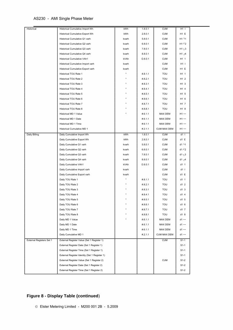
AS230 - AMI Single Phase Meter
© Elster Metering Limited - M200 001 2B - 5.2009
Historical Historical Cumulative Import Wh kWh 1.8.0.1 CUM H1 I
Historical Cumulative Export Wh kWh 2.8.0.1 CUM H1 E
Historical Cumulative Q1 varh kvarh 5.8.0.1 CUM H1 └1
Historical Cumulative Q2 varh kvarh 6.8.0.1 CUM H1 ┘2
Historical Cumulative Q3 varh kvarh 7.8.0.1 CUM H1 ┐3
Historical Cumulative Q4 varh kvarh 8.8.0.1 CUM H1 ┌4
Historical Cumulative VAh1 kVAh D.8.0.1 CUM H1 1
Historical Cumulative Import varh kvarh CUM H1 I
Historical Cumulative Export varh kvarh CUM H1 E
Historical TOU Rate 1 * #.8.1.1 TOU H1 1
Historical TOU Rate 2 * #.8.2.1 TOU H1 2
Historical TOU Rate 3 * #.8.3.1 TOU H1 3
Historical TOU Rate 4 * #.8.4.1 TOU H1 4
Historical TOU Rate 5 * #.8.5.1 TOU H1 5
Historical TOU Rate 6 * #.8.6.1 TOU H1 6
Historical TOU Rate 7 * #.8.7.1 TOU H1 7
Historical TOU Rate 8 * #.8.8.1 TOU H1 8
Historical MD 1 Value * #.6.1.1 MAX DEM H1 ~~
Historical MD 1 Date #.6.1.1 MAX DEM H1 ~~
Historical MD 1 Time #.6.1.1 MAX DEM H1 ~~
Historical Cumulative MD 1 #.2.1.1 CUM MAX DEM H1 ~~
Daily Billing Daily Cumulative Import Wh kWh 1.8.0.1 CUM d1 I
Daily Cumulative Export Wh kWh 2.8.0.1 CUM d1 E
Daily Cumulative Q1 varh kvarh 5.8.0.1 CUM d1 └1
Daily Cumulative Q2 varh kvarh 6.8.0.1 CUM d1 ┘2
Daily Cumulative Q3 varh kvarh 7.8.0.1 CUM d1 ┐3
Daily Cumulative Q4 varh kvarh 8.8.0.1 CUM d1 ┌4
Daily Cumulative VAh1 kVAh D.8.0.1 CUM d1 1
Daily Cumulative Import varh kvarh CUM d1 I
Daily Cumulative Export varh kvarh CUM d1 E
Daily TOU Rate 1 * #.8.1.1 TOU d1 1
Daily TOU Rate 2 * #.8.2.1 TOU d1 2
Daily TOU Rate 3 * #.8.3.1 TOU d1 3
Daily TOU Rate 4 * #.8.4.1 TOU d1 4
Daily TOU Rate 5 * #.8.5.1 TOU d1 5
Daily TOU Rate 6 * #.8.6.1 TOU d1 6
Daily TOU Rate 7 * #.8.7.1 TOU d1 7
Daily TOU Rate 8 * #.8.8.1 TOU d1 8
Daily MD 1 Value * #.6.1.1 MAX DEM d1 ~~
Daily MD 1 Date #.6.1.1 MAX DEM d1 ~~
Daily MD 1 Time #.6.1.1 MAX DEM d1 ~~
Daily Cumulative MD 1 #.2.1.1 CUM MAX DEM d1 ~~
External Registers Set 1 External Register Value (Set 1 Register 1) CUM S1-1
External Register Date (Set 1 Register 1) S1-1
External Register Time (Set 1 Register 1) S1-1
External Register Identity (Set 1 Register 1) S1-1
External Register Value (Set 1 Register 2) CUM S1-2
External Register Date (Set 1 Register 2) S1-2
External Register Time (Set 1 Register 2) S1-2
Figure 8 - Display Table (continued)

Operating & Maintenance Instructions 61
External Register Identity (Set 1 Register 2) S1-2
External Register Value (Set 1 Register 3) CUM S1-3
External Register Date (Set 1 Register 3) S1-3
External Register Time (Set 1 Register 3) S1-3
External Register Identity (Set 1 Register 3) S1-3
External Register Value (Set 1 Register 4) CUM S1-4
External Register Date (Set 1 Register 4) S1-4
External Register Time (Set 1 Register 4) S1-4
External Register Identity (Set 1 Register 4) S1-4
External Registers Set 2 External Register Value (Set 2 Register 1) CUM S2-1
External Register Date (Set 2 Register 1) S2-1
External Register Time (Set 2 Register 1) S2-1
External Register Identity (Set 2 Register 1) S2-1
External Register Value (Set 2 Register 2) CUM S2-2
External Register Date (Set 2 Register 2) S2-2
External Register Time (Set 2 Register 2) S2-2
External Register Identity (Set 2 Register 2) S2-2
External Register Value (Set 2 Register 3) CUM S2-3
External Register Date (Set 2 Register 3) S2-3
External Register Time (Set 2 Register 3) S2-3
External Register Identity (Set 2 Register 3) S2-3
External Register Value (Set 2 Register 4) CUM S2-4
External Register Date (Set 2 Register 4) S2-4
External Register Time (Set 2 Register 4) S2-4
External Register Identity (Set 2 Register 4) S2-4
External Registers Set 3 External Register Value (Set 3 Register 1) CUM S3-1
External Register Date (Set 3 Register 1) S3-1
External Register Time (Set 3 Register 1) S3-1
External Register Identity (Set 3 Register 1) S3-1
External Register Value (Set 3 Register 2) CUM S3-2
External Register Date (Set 3 Register 2) S3-2
External Register Time (Set 3 Register 2) S3-2
External Register Identity (Set 3 Register 2) S3-2
External Register Value (Set 3 Register 3) CUM S3-3
External Register Date (Set 3 Register 3) S3-3
External Register Time (Set 3 Register 3) S3-3
External Register Identity (Set 3 Register 3) S3-3
External Register Value (Set 3 Register 4) CUM S3-4
External Register Date (Set 3 Register 4) S3-4
External Register Time (Set 3 Register 4) S3-4
External Register Identity (Set 3 Register 4) S3-4
Notes: *
Determined by TOU/MD source
# OBIS character determined by TOU/MD Source (1,2,5,6,7,8,D or -)
~~ English text determined by TOU/MD Source (I, E, └1, ┘2, ┐3, ┌4, 1 or blank)
Figure 8 - Display Table (continued)
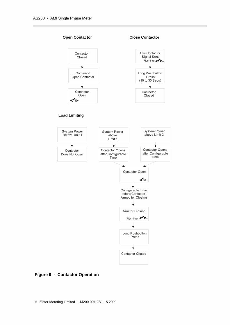
AS230 - AMI Single Phase Meter
© Elster Metering Limited - M200 001 2B - 5.2009
Open Contactor Close Contactor
ContactorClosed
CommandOpen Contactor
ContactorOpen
Arm Contactor Signal Sent
Long PushbuttonPress
(10 to 30 Secs)
ContactorClosed
(Flashing)
Load Limiting
Arm for Closing
(Flashing)
System PowerBelow Limit 1
ContactorDoes Not Open
System PoweraboveLimit 1
Contactor Opensafter Configurable
Time
System Powerabove Limit 2
Contactor Opensafter Configurable
Time
Contactor Open
Configurable Time before Contactor Armed for Closing
Long PushbuttonPress
Contactor Closed
Figure 9 - Contactor Operation

Operating & Maintenance Instructions 63
Level 0 (Correct level 0 password [Read only])
Meter Serial Number
Meter Scheme Id
Level 1 (Correct level 1 password [Read only])
All data listed at level 0
Half hourly values of Load Profile
Total cumulative Active Energy
Total cumulative Reactive Energy
Total cumulative VA
Maximum Demand Register (MD)
Time of Use Registers
Alarm indications
Level 2 (Correct level 2 password [Read and Program])
All data listed in level 0 and 1
Correction to the time and date
End of Billing
Time set
Level 3 (Correct level 3 password [Read and Program])
All operations listed in levels 0, 1 and 2
Programming
Setting the passwords for Levels 1, 2 and 3
Protocol Timeouts
Figure 10 – Password Access Levels
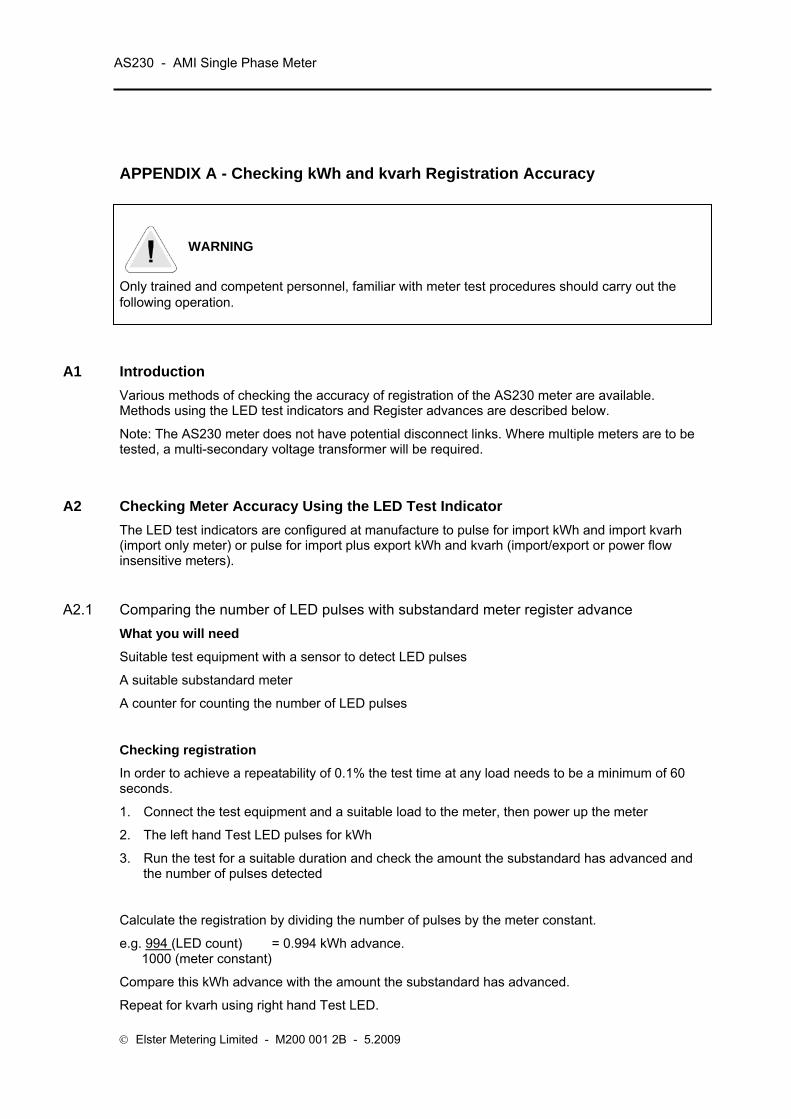
AS230 - AMI Single Phase Meter
© Elster Metering Limited - M200 001 2B - 5.2009
APPENDIX A - Checking kWh and kvarh Registration Accuracy
WARNING
Only trained and competent personnel, familiar with meter test procedures should carry out the following operation.
A1 Introduction Various methods of checking the accuracy of registration of the AS230 meter are available. Methods using the LED test indicators and Register advances are described below.
Note: The AS230 meter does not have potential disconnect links. Where multiple meters are to be tested, a multi-secondary voltage transformer will be required.
A2 Checking Meter Accuracy Using the LED Test Indicator The LED test indicators are configured at manufacture to pulse for import kWh and import kvarh (import only meter) or pulse for import plus export kWh and kvarh (import/export or power flow insensitive meters).
A2.1 Comparing the number of LED pulses with substandard meter register advance What you will need
Suitable test equipment with a sensor to detect LED pulses
A suitable substandard meter
A counter for counting the number of LED pulses
Checking registration
In order to achieve a repeatability of 0.1% the test time at any load needs to be a minimum of 60 seconds.
1. Connect the test equipment and a suitable load to the meter, then power up the meter
2. The left hand Test LED pulses for kWh
3. Run the test for a suitable duration and check the amount the substandard has advanced and the number of pulses detected
Calculate the registration by dividing the number of pulses by the meter constant.
e.g. 994 (LED count) = 0.994 kWh advance. 1000 (meter constant)
Compare this kWh advance with the amount the substandard has advanced.
Repeat for kvarh using right hand Test LED.

Operating & Maintenance Instructions 65
A2.2 Comparing LED pulses with substandard meter pulses
This method may be used where the test equipment has the facility to calculate meter errors based on the pulse output from a substandard meter. It will be necessary to set the pulse value of the meter under test (shown on the meter nameplate) into the meter test equipment.
The duration of each test must be at least 60 seconds
The number of LED pulses should be greater than:-
Itest x V x PF x K Itest = Test current
1000 x 60 V = System voltage
PF = Power factor of test load
K = LED pulse value, impulses/kWh
A3 Checking Meter Registration Accuracy from Register Advances For these methods the advance of the meter register is used rather than the LED Test Indicator.
A3.1 Using the 'Dial Test' values on the meter display Meters may be set to show cumulative kWh and kvarh registers with maximum possible resolution by using Power Master Unit instructions via the optical or RS232 port. Energy register displays will then have 2 decimal digits.
The display resolution will revert to normal when a further appropriate instruction is received, or after 24 hours.
What you will need
A suitable supply and load or a meter test bench
Substandard meter with a kWh (kvarh) display
For each measured quantity:
1. Connect the meter and substandard meter to the supply
2. Instruct the meter to show register to suitable dial test resolution
3. Record initial values of the meter and substandard meter registers
4. Apply a suitable load to cause a significant register advance
5. Switch off the load to stop the register advancing. Leave the supply connected
6. Record the final register readings, compute the advances and compare the meter advance with the substandard advance


Elster Metering Systems Tollgate Business Park Beaconside, Stafford Staffordshire ST16 3HS United Kingdom Tel. 44 (0) 1785 275200 Web: www. elstermetering.com
The company’s policy is one of continuous product improvement and the right is reserved to modify the specification contained herein without notice.
About Elster Group Elster Group is the world’s leading manufacturer and supplier of highly accurate, high quality, integrated metering and utilisation solutions to the gas, electricity and water industries.
In addition, through its subsidiary Ipsen International, it is the leading global manufacturer of high-level thermochemical treatment equipment.
The group has over 9,000 staff and operations in 38 countries, focused in North and South America, Europe and Asia. Elster’s high quality products and systems reflect the wealth of knowledge and experience gained from over 170 years of dedication to measuring energy and scarce natural resources.