AMI (ADVANCED METERING INFRASTRUCTURE) WATER METERS …
1
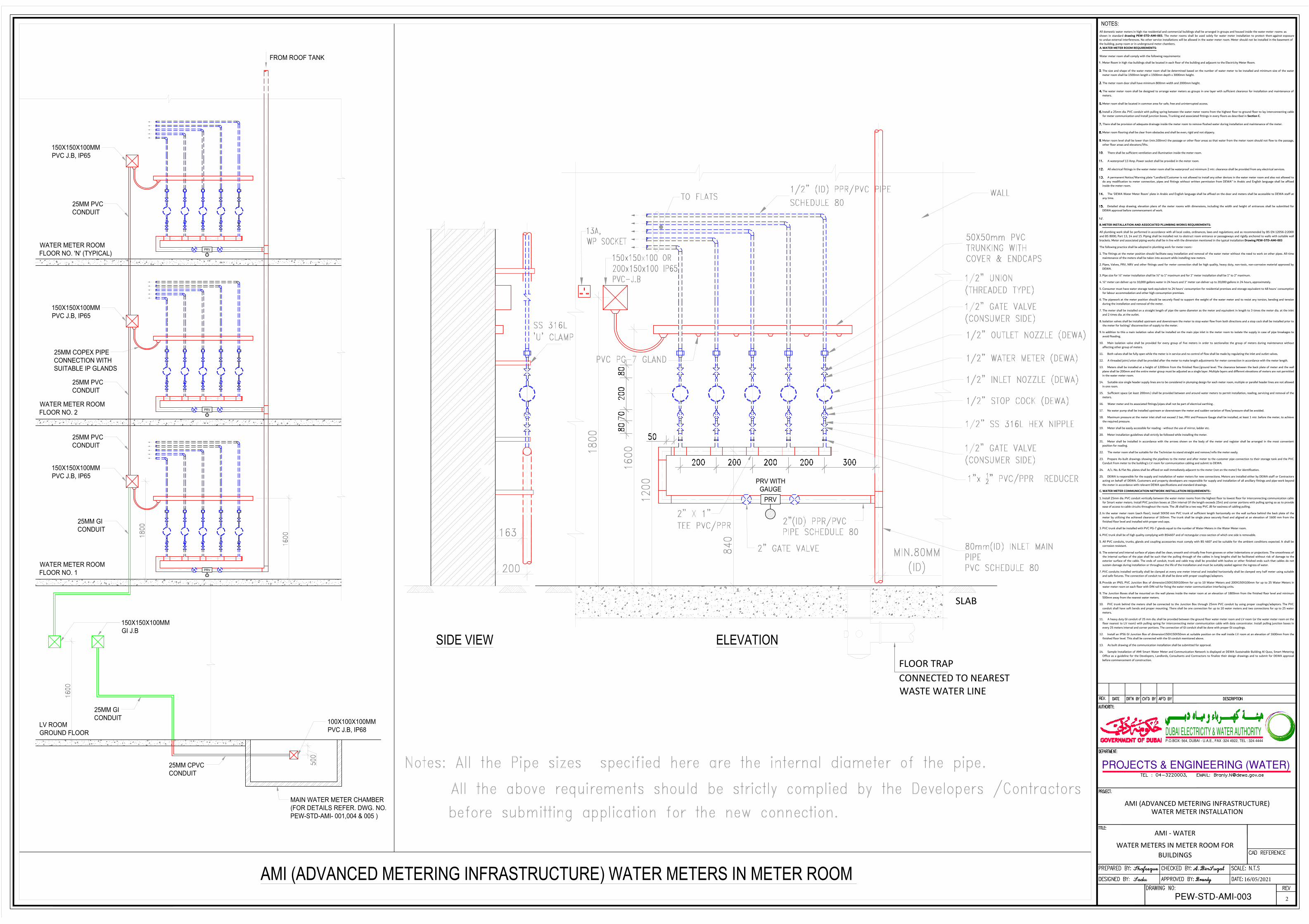
AMI (ADVANCED METERING INFRASTRUCTURE) WATER METERS IN METER ROOM ELEVATION SIDE VIEW SLAB CONNECTED TO NEAREST FLOOR TRAP WASTE WATER LINE WATER METER ROOM FLOOR NO. 'N' (TYPICAL) LV ROOM GROUND FLOOR 150X150X100MM GI J.B WATER METER ROOM FLOOR NO. 1 WATER METER ROOM FLOOR NO. 2 100X100X100MM PVC J.B, IP68 150X150X100MM PVC J.B, IP65 FROM ROOF TANK 150X150X100MM PVC J.B, IP65 25MM PVC CONDUIT 25MM PVC CONDUIT 25MM GI CONDUIT MAIN WATER METER CHAMBER (FOR DETAILS REFER. DWG. NO. PEW-STD-AMI- 001,004 & 005 ) 150X150X100MM PVC J.B, IP65 25MM CPVC CONDUIT 25MM PVC CONDUIT 25MM GI CONDUIT 25MM COPEX PIPE CONNECTION WITH SUITABLE IP GLANDS PRV WITH GAUGE PRV PRV PRV PRV AMI - WATER WATER METERS IN METER ROOM FOR BUILDINGS PROJECTS & ENGINEERING (WATER) DUBAI ELECTRICITY & WATER AUTHORITY P.O.BOX: 564, DUBAI - U.A.E., FAX :324 4922, TEL : 324 4444 AMI (ADVANCED METERING INFRASTRUCTURE) WATER METER INSTALLATION All domestic water meters in high rise residential and commercial buildings shall be arranged in groups and housed inside the water meter rooms as shown in standard drawing PEW-STD-AMI-003. The meter rooms shall be used solely for water meter installation to protect them against exposure to undue external interferences. No other service installations will be allowed in the water meter room. Meter should not be installed in the basement of the building, pump room or in underground meter chambers. A. WATER METER ROOM REQUIREMENTS: Water meter room shall comply with the following requirements: Meter Room in high rise buildings shall be located in each floor of the building and adjacent to the Electricity Meter Room. The size and shape of the water meter room shall be determined based on the number of water meter to be installed and minimum size of the water meter room shall be 1500mm length x 1500mm depth x 3000mm height. The meter room door shall have minimum 800mm width and 2000mm height. The water meter room shall be designed to arrange water meters as groups in one layer with sufficient clearance for installation and maintenance of meters. Meter room shall be located in common area for safe, free and uninterrupted access. Install a 25mm dia. PVC conduit with pulling spring between the water meter rooms from the highest floor to ground floor to lay interconnecting cable for meter communication and Install junction boxes, Trunking and associated fittings in every floors as described in Section C. There shall be provision of adequate drainage inside the meter room to remove flushed water during installation and maintenance of the meter. Meter room flooring shall be clear from obstacles and shall be even, rigid and not slippery. Meter room level shall be lower than (min.100mm) the passage or other floor areas so that water from the meter room should not flow to the passage, other floor areas and elevators/lifts. There shall be sufficient ventilation and illumination inside the meter room. A waterproof 13 Amp. Power socket shall be provided in the meter room. All electrical fittings in the water meter room shall be waterproof and minimum 2 mtr. clearance shall be provided from any electrical services. A permanent Notice/Warning plate “Landlord/Customer is not allowed to install any other devices in the water meter room and also not allowed to do any modification to meter connection, pipes and fittings without written permission from DEWA” in Arabic and English language shall be affixed inside the meter room. The 'DEWA Water Meter Room' plate in Arabic and English language shall be affixed on the door and meters shall be accessible to DEWA staff at any time. Detailed shop drawing, elevation plans of the meter rooms with dimensions, including the width and height of entrances shall be submitted for DEWA approval before commencement of work. B. METER INSTALLATION AND ASSOCIATED PLUMBING WORKS REQUIREMENTS: All plumbing work shall be performed in accordance with all local codes, ordinances, laws and regulations; and as recommended by BS EN 12056-2:2000 and BS 8000, Part 13, 14 and 15. Piping shall be installed not to obstruct room entrance or passageways and rigidly anchored to walls with suitable wall brackets. Meter and associated piping works shall be in line with the dimension mentioned in the typical installation Drawing PEW-STD-AMI-003 The following practice shall be adopted in plumbing work for meter room:- 1. The fittings at the meter position should facilitate easy installation and removal of the water meter without the need to work on other pipes. All-time maintenance of the meters shall be taken into account while installing new meters. 2. Pipes, Valves, PRV, NRV and other fittings used for meter connection shall be high quality, heavy duty, non-toxic, non-corrosive material approved by DEWA. 3. Pipe size for ½” meter installation shall be ½” to 1” maximum and for 1” meter installation shall be 1” to 2” maximum. 4. ½” meter can deliver up to 10,000 gallons water in 24 hours and 1” meter can deliver up to 20,000 gallons in 24 hours, approximately. 5. Consumer must have water storage tank equivalent to 24 hours' consumption for residential premises and storage equivalent to 48 hours' consumption for labour accommodation and other high consumption premises. 6. The pipework at the meter position should be securely fixed to support the weight of the water meter and to resist any torsion, bending and tension during the installation and removal of the meter. 7. The meter shall be installed on a straight length of pipe the same diameter as the meter and equivalent in length to 3 times the meter dia. at the inlet and 2 times dia. at the outlet. 8. Isolation valves shall be installed upstream and downstream the meter to stop water flow from both directions and a stop cock shall be installed prior to the meter for locking/ disconnection of supply to the meter. 9. In addition to this a main isolation valve shall be installed on the main pipe inlet in the meter room to isolate the supply in case of pipe breakages to avoid flooding. 10. Main isolation valve shall be provided for every group of five meters in order to sectionalize the group of meters during maintenance without affecting other group of meters. 11. Both valves shall be fully open while the meter is in service and no control of flow shall be made by regulating the inlet and outlet valves. 12. A threaded joint/union shall be provided after the meter to make length adjustments for meter connection in accordance with the meter length. 13. Meters shall be installed at a height of 1200mm from the finished floor/ground level. The clearance between the back plate of meter and the wall plane shall be 200mm and the entire meter group must be adjusted as a single layer. Multiple layers and different elevations of meters are not permitted in the water meter room. 14. Suitable size single header supply lines are to be considered in plumping design for each meter room, multiple or parallel header lines are not allowed in one room. 15. Sufficient space (at least 200mm.) shall be provided between and around water meters to permit installation, reading, servicing and removal of the meters. 16. Water meter and its associated fittings/pipes shall not be part of electrical earthing . 17. No water pump shall be installed upstream or downstream the meter and sudden variation of flow/pressure shall be avoided. 18. Maximum pressure at the meter inlet shall not exceed 2 bar, PRV and Pressure Gauge shall be installed, at least 1 mtr. before the meter, to achieve the required pressure. 19. Meter shall be easily accessible for reading - without the use of mirror, ladder etc. 20. Meter installation guidelines shall strictly be followed while installing the meter. 21. Meter shall be installed in accordance with the arrows shown on the body of the meter and register shall be arranged in the most convenient position for reading. 22. The meter room shall be suitable for the Technician to stand straight and remove/refix the meter easily. 23. Prepare As-built drawings showing the pipelines to the meter and after meter to the customer pipe connection to their storage tank and the PVC Conduit from meter to the building's LV room for communication cabling and submit to DEWA. 24. A/c. No. & Flat No. plates shall be affixed on wall immediately adjacent to the meter (not on the meter) for identification. 25. DEWA is responsible for the supply and installation of water meters for new connections. Meters are installed either by DEWA staff or Contractors acting on behalf of DEWA. Customers and property developers are responsible for supply and installation of all ancillary fittings and pipe-work beyond the meter in accordance with relevant DEWA specifications and standard drawings. C. WATER METER COMMUNICATION NETWORK INSTALLATION REQUIREMENTS : 1. Install 25mm dia. PVC conduit vertically between the water meter rooms from the highest floor to lowest floor for interconnecting communication cable for Smart water meters. Install PVC junction boxes at 25m interval (if the length exceeds 25m) and corner portions with pulling spring so as to provide ease of access to cable circuits throughout the route. The JB shall be a two way PVC JB for easiness of cabling pulling. 2. In the water meter room (each floor), install 50X50 mm PVC trunk of sufficient length horizontally on the wall surface behind the back plate of the meter by utilizing the achieved clearance of 165mm. The trunk shall be single piece securely fixed and aligned at an elevation of 1600 mm from the finished floor level and installed with proper end caps. 3. PVC trunk shall be installed with PVC PG-7 glands equal to the number of Water Meters in the Water Meter room. 4. PVC trunk shall be of high quality complying with BS4607 and of rectangular cross-section of which one side is removable. 5. All PVC conduits, trunks, glands and coupling accessories must comply with BS 4607 and be suitable for the ambient conditions expected. It shall be corrosion resistant. 6. The external and internal surface of pipes shall be clean, smooth and virtually free from grooves or other indentations or projections. The smoothness of the internal surface of the pipe shall be such that the pulling through of the cables in long lengths shall be facilitated without risk of damage to the exterior surface of the cable. The ends of conduit, trunk and cable tray shall be provided with bushes or other finished ends such that cables do not sustain damage during installation or throughout the life of the Installation and must be suitably sealed against the ingress of water. 7. PVC conduits installed vertically shall be clamped at every one meter interval and installed horizontally shall be clamped very half meter using suitable and safe fixtures. The connection of conduit to JB shall be done with proper couplings/adaptors. 8. Provide an IP65, PVC Junction Box of dimension150X150X100mm for up to 10 Water Meters and 200X150X100mm for up to 25 Water Meters in water meter room on each floor with DIN rail for fixing the water meter communication interfacing units. 9. The Junction Boxes shall be mounted on the wall planes inside the meter room at an elevation of 1800mm from the finished floor level and minimum 500mm away from the nearest water meters. 10. PVC trunk behind the meters shall be connected to the Junction Box through 25mm PVC conduit by using proper couplings/adaptors. The PVC conduit shall have soft bends and proper mounting. There shall be one connection for up to 10 water meters and two connections for up to 25 water meters. 11. A heavy duty GI conduit of 25 mm dia. shall be provided between the ground floor water meter room and LV room (or the water meter room on the floor nearest to LV room) with pulling spring for interconnecting meter communication cable with data concentrator. Install pulling junction boxes in every 25 meters interval and corner portions. The connection of GI conduit shall be done with proper GI couplings. 12. Install an IP56 GI Junction Box of dimension150X150X50mm at suitable position on the wall inside LV room at an elevation of 1600mm from the finished floor level. This shall be connected with the GI conduit mentioned above. 13. As built drawing of the communication installation shall be submitted for approval. 14. Sample Installation of AMI Smart Water Meter and Communication Network is displayed at DEWA Sustainable Building Al Quoz, Smart Metering Office as a guideline for the Developers, Landlords, Consultants and Contractors to finalize their design drawings and to submit for DEWA approval before commencement of construction. NOTES: PEW-STD-AMI-003 99 16/05/2021 2
Transcript of AMI (ADVANCED METERING INFRASTRUCTURE) WATER METERS …
AMI (ADVANCED METERING INFRASTRUCTURE) WATER METERS IN METER ROOM
ELEVATIONSIDE VIEW
SLAB
CONNECTED TO NEAREST FLOOR TRAP
WASTE WATER LINE
WATER METER ROOM
FLOOR NO. 'N' (TYPICAL)
LV ROOM
GROUND FLOOR
150X150X100MM
GI J.B
WATER METER ROOM
FLOOR NO. 1
WATER METER ROOM
FLOOR NO. 2
100X100X100MM
PVC J.B, IP68
150X150X100MM
PVC J.B, IP65
FROM ROOF TANK
150X150X100MM
PVC J.B, IP65
25MM PVC
CONDUIT
25MM PVC
CONDUIT
25MM GI
CONDUIT
MAIN WATER METER CHAMBER
(FOR DETAILS REFER. DWG. NO.
PEW-STD-AMI- 001,004 & 005 )
150X150X100MM
PVC J.B, IP65
25MM CPVC
CONDUIT
25MM PVC
CONDUIT
25MM GI
CONDUIT
25MM COPEX PIPE
CONNECTION WITH
SUITABLE IP GLANDS
PRV WITH
GAUGE
PRV
PRV
PRV
PRV
900
AMI - WATER
WATER METERS IN METER ROOM FOR BUILDINGS
PROJECTS & ENGINEERING (WATER)
DUBAI ELECTRICITY & WATER AUTHORITYP.O.BOX: 564, DUBAI - U.A.E., FAX :324 4922, TEL : 324 4444
AMI (ADVANCED METERING INFRASTRUCTURE)WATER METER INSTALLATION
All domestic water meters in high rise residential and commercial buildings shall be arranged in groups and housed inside the water meter rooms as
shown in standard drawing PEW-STD-AMI-003. The meter rooms shall be used solely for water meter installation to protect them against exposure
to undue external interferences. No other service installations will be allowed in the water meter room. Meter should not be installed in the basement of
the building, pump room or in underground meter chambers.
A.WATER METER ROOM REQUIREMENTS:
Water meter room shall comply with the following requirements:
Meter Room in high rise buildings shall be located in each floor of the building and adjacent to the Electricity Meter Room.
The size and shape of the water meter room shall be determined based on the number of water meter to be installed and minimum size of the water
meter room shall be 1500mm length x 1500mm depth x 3000mm height.
The meter room door shall have minimum 800mm width and 2000mm height.
The water meter room shall be designed to arrange water meters as groups in one layer with sufficient clearance for installation and maintenance of
meters.
Meter room shall be located in common area for safe, free and uninterrupted access.
Install a 25mm dia. PVC conduit with pulling spring between the water meter rooms from the highest floor to ground floor to lay interconnecting cable
for meter communication and Install junction boxes, Trunking and associated fittings in every floors as described in Section C.
There shall be provision of adequate drainage inside the meter room to remove flushed water during installation and maintenance of the meter.
Meter room flooring shall be clear from obstacles and shall be even, rigid and not slippery.
Meter room level shall be lower than (min.100mm) the passage or other floor areas so that water from the meter room should not flow to the passage,
other floor areas and elevators/lifts.
There shall be sufficient ventilation and illumination inside the meter room.
A waterproof 13 Amp. Power socket shall be provided in the meter room.
All electrical fittings in the water meter room shall be waterproof and minimum 2 mtr. clearance shall be provided from any electrical services.
A permanent Notice/Warning plate “Landlord/Customer is not allowed to install any other devices in the water meter room and also not allowed to
do any modification to meter connection, pipes and fittings without written permission from DEWA” in Arabic and English language shall be affixed
inside the meter room.
The 'DEWA Water Meter Room' plate in Arabic and English language shall be affixed on the door and meters shall be accessible to DEWA staff at
any time.
Detailed shop drawing, elevation plans of the meter rooms with dimensions, including the width and height of entrances shall be submitted for
DEWA approval before commencement of work.
B. METER INSTALLATION AND ASSOCIATED PLUMBING WORKS REQUIREMENTS:
All plumbing work shall be performed in accordance with all local codes, ordinances, laws and regulations; and as recommended by BS EN 12056-2:2000
and BS 8000, Part 13, 14 and 15. Piping shall be installed not to obstruct room entrance or passageways and rigidly anchored to walls with suitable wall
brackets. Meter and associated piping works shall be in line with the dimension mentioned in the typical installation Drawing PEW-STD-AMI-003
The following practice shall be adopted in plumbing work for meter room:-
1. The fittings at the meter position should facilitate easy installation and removal of the water meter without the need to work on other pipes. All-time
maintenance of the meters shall be taken into account while installing new meters.
2. Pipes, Valves, PRV, NRV and other fittings used for meter connection shall be high quality, heavy duty, non-toxic, non-corrosive material approved by
DEWA.
3. Pipe size for ½” meter installation shall be ½” to 1” maximum and for 1” meter installation shall be 1” to 2” maximum.
4. ½” meter can deliver up to 10,000 gallons water in 24 hours and 1” meter can deliver up to 20,000 gallons in 24 hours, approximately.
5. Consumer must have water storage tank equivalent to 24 hours' consumption for residential premises and storage equivalent to 48 hours' consumption
for labour accommodation and other high consumption premises.
6. The pipework at the meter position should be securely fixed to support the weight of the water meter and to resist any torsion, bending and tension
during the installation and removal of the meter.
7. The meter shall be installed on a straight length of pipe the same diameter as the meter and equivalent in length to 3 times the meter dia. at the inlet
and 2 times dia. at the outlet.
8. Isolation valves shall be installed upstream and downstream the meter to stop water flow from both directions and a stop cock shall be installed prior to
the meter for locking/ disconnection of supply to the meter.
9. In addition to this a main isolation valve shall be installed on the main pipe inlet in the meter room to isolate the supply in case of pipe breakages to
avoid flooding.
10. Main isolation valve shall be provided for every group of five meters in order to sectionalize the group of meters during maintenance without
affecting other group of meters.
11. Both valves shall be fully open while the meter is in service and no control of flow shall be made by regulating the inlet and outlet valves.
12. A threaded joint/union shall be provided after the meter to make length adjustments for meter connection in accordance with the meter length.
13. Meters shall be installed at a height of 1200mm from the finished floor/ground level. The clearance between the back plate of meter and the wall
plane shall be 200mm and the entire meter group must be adjusted as a single layer. Multiple layers and different elevations of meters are not permitted
in the water meter room.
14. Suitable size single header supply lines are to be considered in plumping design for each meter room, multiple or parallel header lines are not allowed
in one room.
15. Sufficient space (at least 200mm.) shall be provided between and around water meters to permit installation, reading, servicing and removal of the
meters.
16. Water meter and its associated fittings/pipes shall not be part of electrical earthing .
17. No water pump shall be installed upstream or downstream the meter and sudden variation of flow/pressure shall be avoided.
18. Maximum pressure at the meter inlet shall not exceed 2 bar, PRV and Pressure Gauge shall be installed, at least 1 mtr. before the meter, to achieve
the required pressure.
19. Meter shall be easily accessible for reading - without the use of mirror, ladder etc.
20. Meter installation guidelines shall strictly be followed while installing the meter.
21. Meter shall be installed in accordance with the arrows shown on the body of the meter and register shall be arranged in the most convenient
position for reading.
22. The meter room shall be suitable for the Technician to stand straight and remove/refix the meter easily.
23. Prepare As-built drawings showing the pipelines to the meter and after meter to the customer pipe connection to their storage tank and the PVC
Conduit from meter to the building's LV room for communication cabling and submit to DEWA.
24. A/c. No. & Flat No. plates shall be affixed on wall immediately adjacent to the meter (not on the meter) for identification.
25. DEWA is responsible for the supply and installation of water meters for new connections. Meters are installed either by DEWA staff or Contractors
acting on behalf of DEWA. Customers and property developers are responsible for supply and installation of all ancillary fittings and pipe-work beyond
the meter in accordance with relevant DEWA specifications and standard drawings.
C. WATER METER COMMUNICATION NETWORK INSTALLATION REQUIREMENTS :
1. Install 25mm dia. PVC conduit vertically between the water meter rooms from the highest floor to lowest floor for interconnecting communication cable
for Smart water meters. Install PVC junction boxes at 25m interval (if the length exceeds 25m) and corner portions with pulling spring so as to provide
ease of access to cable circuits throughout the route. The JB shall be a two way PVC JB for easiness of cabling pulling.
2. In the water meter room (each floor), install 50X50 mm PVC trunk of sufficient length horizontally on the wall surface behind the back plate of the
meter by utilizing the achieved clearance of 165mm. The trunk shall be single piece securely fixed and aligned at an elevation of 1600 mm from the
finished floor level and installed with proper end caps.
3. PVC trunk shall be installed with PVC PG-7 glands equal to the number of Water Meters in the Water Meter room.
4. PVC trunk shall be of high quality complying with BS4607 and of rectangular cross-section of which one side is removable.
5. All PVC conduits, trunks, glands and coupling accessories must comply with BS 4607 and be suitable for the ambient conditions expected. It shall be
corrosion resistant.
6. The external and internal surface of pipes shall be clean, smooth and virtually free from grooves or other indentations or projections. The smoothness of
the internal surface of the pipe shall be such that the pulling through of the cables in long lengths shall be facilitated without risk of damage to the
exterior surface of the cable. The ends of conduit, trunk and cable tray shall be provided with bushes or other finished ends such that cables do not
sustain damage during installation or throughout the life of the Installation and must be suitably sealed against the ingress of water.
7. PVC conduits installed vertically shall be clamped at every one meter interval and installed horizontally shall be clamped very half meter using suitable
and safe fixtures. The connection of conduit to JB shall be done with proper couplings/adaptors.
8. Provide an IP65, PVC Junction Box of dimension150X150X100mm for up to 10 Water Meters and 200X150X100mm for up to 25 Water Meters in
water meter room on each floor with DIN rail for fixing the water meter communication interfacing units.
9. The Junction Boxes shall be mounted on the wall planes inside the meter room at an elevation of 1800mm from the finished floor level and minimum
500mm away from the nearest water meters.
10. PVC trunk behind the meters shall be connected to the Junction Box through 25mm PVC conduit by using proper couplings/adaptors. The PVC
conduit shall have soft bends and proper mounting. There shall be one connection for up to 10 water meters and two connections for up to 25 water
meters.
11. A heavy duty GI conduit of 25 mm dia. shall be provided between the ground floor water meter room and LV room (or the water meter room on the
floor nearest to LV room) with pulling spring for interconnecting meter communication cable with data concentrator. Install pulling junction boxes in
every 25 meters interval and corner portions. The connection of GI conduit shall be done with proper GI couplings.
12. Install an IP56 GI Junction Box of dimension150X150X50mm at suitable position on the wall inside LV room at an elevation of 1600mm from the
finished floor level. This shall be connected with the GI conduit mentioned above.
13. As built drawing of the communication installation shall be submitted for approval.
14. Sample Installation of AMI Smart Water Meter and Communication Network is displayed at DEWA Sustainable Building Al Quoz, Smart Metering
Office as a guideline for the Developers, Landlords, Consultants and Contractors to finalize their design drawings and to submit for DEWA approval
before commencement of construction.
NOTES:
PEW-STD-AMI-003
99
16/05/2021
2
AutoCAD SHX Text
TO FLATS
AutoCAD SHX Text
1/2" WATER METER (DEWA)
AutoCAD SHX Text
1/2" INLET NOZZLE (DEWA)
AutoCAD SHX Text
1/2" OUTLET NOZZLE (DEWA)
AutoCAD SHX Text
WALL
AutoCAD SHX Text
2" GATE VALVE
AutoCAD SHX Text
1/2" (ID) PPR/PVC PIPE
AutoCAD SHX Text
1/2" STOP COCK (DEWA)
AutoCAD SHX Text
1/2" GATE VALVE (CONSUMER SIDE)
AutoCAD SHX Text
1/2" UNION (THREADED TYPE)
AutoCAD SHX Text
150x150x100 OR 200x150x100 IP65 PVC-J.B
AutoCAD SHX Text
50X50mm PVC TRUNKING WITH COVER & ENDCAPS
AutoCAD SHX Text
1/2" GATE VALVE (CONSUMER SIDE)
AutoCAD SHX Text
SS 316L 'U' CLAMP
AutoCAD SHX Text
80mm(ID) INLET MAIN PIPE PVC SCHEDULE 80
AutoCAD SHX Text
PVC PG-7 GLAND
AutoCAD SHX Text
1"x " PVC/PPR REDUCER12" PVC/PPR REDUCER
AutoCAD SHX Text
2"(ID) PPR/PVC PIPE SCHEDULE 80
AutoCAD SHX Text
2" X 1" TEE PVC/PPR
AutoCAD SHX Text
1/2" SS 316L HEX NIPPLE
AutoCAD SHX Text
SCHEDULE 80
AutoCAD SHX Text
13A, WP SOCKET
AutoCAD SHX Text
All the above requirements should be strictly complied by the Developers /Contractors
AutoCAD SHX Text
before submitting application for the new connection.
AutoCAD SHX Text
Notes: All the Pipe sizes specified here are the internal diameter of the pipe.
AutoCAD SHX Text
DRAWING NO:
AutoCAD SHX Text
REV
AutoCAD SHX Text
TITLE:
AutoCAD SHX Text
PROJECT:
AutoCAD SHX Text
DR'N BY
AutoCAD SHX Text
CH'D BY
AutoCAD SHX Text
AP'D BY
AutoCAD SHX Text
DATE
AutoCAD SHX Text
REV.
AutoCAD SHX Text
DESCRIPTION
AutoCAD SHX Text
DEPARTMENT:
AutoCAD SHX Text
CAD REFERENCE
AutoCAD SHX Text
AUTHORITY:
AutoCAD SHX Text
1. Meter Room in high rise buildings shall be located in each floor of the building and adjacent to the Electricity Meter Room. 2. The size and shape of the water meter room shall be determined based on the number of water meter to be installed and minimum size of the water 3. The meter room door shall have minimum 800mm width and 2000mm height. 4. The water meter room shall be designed to arrange water meters as groups in one layer with sufficient clearance for installation and maintenance of 5. Meter room shall be located in common area for safe, free and uninterrupted access. 6. Install a 25mm dia. PVC conduit with pulling spring between the water meter rooms from the highest floor to ground floor to lay interconnecting cable 7. There shall be provision of adequate drainage inside the meter room to remove flushed water during installation and maintenance of the meter. 8. Meter room flooring shall be clear from obstacles and shall be even, rigid and not slippery. 9. Meter room level shall be lower than (min.100mm) the passage or other floor areas so that water from the meter room should not flow to the passage, 10. There shall be sufficient ventilation and illumination inside the meter room. 11. A waterproof 13 Amp. Power socket shall be provided in the meter room. 12. All electrical fittings in the water meter room shall be waterproof and minimum 2 mtr. clearance shall be provided from any electrical services. 13. A permanent Notice/Warning plate “Landlord/Customer is not allowed to install any other devices in the water meter room and also not allowed to 14. The 'DEWA Water Meter Room' plate in Arabic and English language shall be affixed on the door and meters shall be accessible to DEWA staff at 15. Detailed shop drawing, elevation plans of the meter rooms with dimensions, including the width and height of entrances shall be submitted for 16. No plumbing work shall commence inside the meter room before the plumbing proposal is inspected and approved by DEWA.
AutoCAD SHX Text
TEL : 04-3220003, EMAIL: [email protected]
AutoCAD SHX Text
PREPARED BY:
AutoCAD SHX Text
DESIGNED BY:
AutoCAD SHX Text
CHECKED BY:
AutoCAD SHX Text
APPROVED BY:
AutoCAD SHX Text
SCALE:
AutoCAD SHX Text
DATE:
AutoCAD SHX Text
Shafeeque
AutoCAD SHX Text
Sadu
AutoCAD SHX Text
A.BinSuqat
AutoCAD SHX Text
Branly
AutoCAD SHX Text
N.T.S
AutoCAD SHX Text
01.07.2020
AutoCAD SHX Text
1