Evaluation of Pedestrian Bridges and Pedestrian Safety in Jordan

ANSI A156.10-1979
American National Standard
for power operated
pedestrian doors
american national standards institute, inc.1430 broadway, new york. new york 10018
0:1:roo~a.o~
o.,(l)
9"VI
"'0(IIno....(l)
'"
ANSI A156.10-197928 November 1980
ACCEPTANCE NOTICE
The above non-Government document was adopted on 28 November 1980and is approved for use by the 000. The indicated industry group hasfurnished the clearance required by existing regulations. Copies of thedocument are stocked by 000 Single Stock Point, Naval Publications andForms Center, Philadelphia, PA 19120 for issue to 000 activities only.Contractors and industry groups must obtain copies from ANSI, 1430 Broadway, New York, NY 10018.
Title of Document:
Date of Specific Issue Adopted:
Releasing Industry Group:
American National Standard forPower Operated Pedestrian Doors
18 July 1979
Builders Hardware ManufacturersAssociation, Inc.
NOTICE: When reaffirmantion, amendment, revision, or cancellationof this standard is initially proposed, the industry group responsible forthis standard shall inform the military coordinating activity of the proposed change and request participation.
Custodians:
Army - MENavy - YO
Review Activity:
DLA - CS
Military Coordinating Activity:
Navy - YO
Project No. 5670-0046
I FSC 5670 I

AN SI A 156. 10- 1979
AMERICAN NATIONAL STANDARD
FOR
POWER OPERA TED PEDESTRIAN DOORS
SPONSOR
BUILDERS HARDWARE MA N UFACTURERS ASSOCIATION, INC.
Approved 18 July 1979
AMERICAN NATIONAL STANDARDS INSTITUTE, INC.
AMERICAN NATIONAL STANDARD
An American National Standard implies a consensus of those substantially concernedwith its scope and provisions. An American National Standard is intended as aguide to aid the manufacturer, the consumer, and the general public. The existenceof an American National Standard does not in any respect preclude anyone, whetherhe has approved the standard or not, from manufacturing, marketing, purchasing, orusing products, processes, or procedures not conforming to the standard. AmericanNational Standards are subject to periodic review and users are cautioned to obtainthe latest editions.
CAUTION NOTICE: This American National Standard may be revised or withdrawn at anytime. The procedures of the American National Standards Institute require thataction be taken to reaffirm, revise, or withdraw this standard no later than fiveyears from the date of publication. Purchasers of American National Standards mayreceive current information on all standards by calling or writing the AmericanNational Standards Institute.
Published byBUILDERS HARDWARE MANUFACTURERS ASSOCIATION, INC.
60 East 42nd Street New York, New York 10165
Copyright 1979 by the Builders Hardware Manufacturers Association, Inc.Not to be reproduced without specific authorization from BHMA
ANSI approval was secured under the canvass method
Printed in the USAl4r~1079/300
61~880/ 3006M1180/300
511881/3005M782/3005r~383/ 3003M484/500
This Standard bears the BHI\i1A designation 1601
FOREWORD The general classification of builders hardware includes a wide varietyof items which are divided into several categories. To recognize thisdiversity, a sectional classification system has been established.Power Operated Doors is one such section and this Standard is the resultof the collective efforts of members of the Builders Hardware ManufacturersAssociation, Inc. who manufacture this product. The total Product Standardseffort is, therefore, a collection of sections, each covering a specificcategory of items.
Performance tests and, where it has been necessary, dimensional requirements have been established to insure a degree of safety. There are norestrictions on design, except for those dimensional requirements imposedfor the reasons given above.
This Standard is not intended to obstruct but rather to encourage thedevelopment of improved products, methods and materials. The BHMArecognizes that errors will be found, items will become obsolete, andnew products, methods and materials will be developed. With this in mind,the Association plans to update, correct and revise these Standards on aregular basis. It shall also be the responsibility of manufacturers torequest such appropriate revisions.

CONTENTS Section
1. General
2. DeFinitions .
3. Control Mats - Appl ications3. 1 Edge of exposed area .3.2 Width of exposed areas .....•......3.3 Safety control mats for sw ing i ng doors .3.4 Control mats for two way swinging
doors .•.........................3.5 Joi ning of control mats .3.6 Meeti ng of control mats at threshold .3.7 Active area .3.8 Length of mats for sl idi ng doors .
4. Performance Requirements of Control Mats4.1 Control mat circuit ..4.2 Resi stance of control mats .4.3 Control mat sensitivity test .4.4 Control mat friction test .4.5 Control mat trim .
5. Sensors5.1 Adjustability .5.2 Detection pattern ..5.3 Auxiliary presence sensor .
6. Photo-cell Systems6.1 Variable time delay .6.2 Mounting of components .6.3 Photo-cell systems for sliding doors ..6.4 Photo-cell systems for swinging doors
Page
11&2222
2222 & 33
333
3333
7. Guide Rails for Swinging Doors7.1 Placement 47.2 Minimum height.................. 47.3 Panels or dividers................. 47.4 CI earances 47.5 Free standing rails................ 4
8. Marking8.1 Arrow sign 48.2 Do not enter sign 48.3 Sig n for slid ing d 00 r 4
8.4 Sign for ingress/egress door 5
9. Reference to other Standards 5

CONTENTS(continued) Section Page
10. Entrapment Protection10. 1 Measurements, how taken 510.2 Force to prevent closing for swinging
doors ...............•.......... 510.3 Opening speed, swinging door..... 510.4 Force to prevent openi ng for
swinging doors 510.5 Closing speed, swinging door...... 510.6 Kinetic energy, swinging door..... 510.7 Force to prevent closing for sliding
doors 510.8 Kinetic energy, sliding doors 510.9 Clearance, swinging doors......... 6
11. General Performance11 . 1 Latch check 611.2 Manual opening force, swinging doors 611.3 Manual opening force, sliding doors 611.4 Panic break out, swinging doors 611.5 Panic break out, sliding doors 611.6 Emergency egress test for swinging
a nd slid ing d 00 rs 6
12. Salt Spray Test12.1 Sample assembly 612.2 Rei ease force pri or to test 612.3 Drying of sample 712.4 Rei ease forces after test 7
Appendix A, Table of Mat Sizes and Illustrations
Appendix B, Definitions
Appendix C, Reference to Other Standards
7 thru 12
13 thru 19
20
BHMA Standard 1601
1. GENERAL 3.2 Width of Exposed Areas
1. 1 Requirements in this Standard applyto power operated swinging and sliding doorsfor pedestrian use and some small vehiculartraffic. Inc! uded are provisi ons intended toreduce the chance of user injury or entrapment.Power operated doors primarily for industrial,vehicular or trained traffic are not covered inthis Standard.
1. 1. 1 Where this Standard containsspecifications relating to minimum or maximumdimensions of various components of poweroperated doors for pedestrian use and somesmall vehicular traffic, such dimensions areincluded to provide user protection for whatare, in the industry, standard applicationconditions. This Standard does not attempt toassess any factors that may exist with respectto custom design installations which mayor maynot meet the requirements of this Standard.
1.2 Required dimensions are expressedfirst and the metric equivalents given inparentheses are approximate.
2. DEFINITIONS
See Appendix B for definitions ofterms used in the Power Operated Door industry.
3. CONTROL MATS - APPLICATlO NS(See Tables 1-A and 2-A)
3. 1 The edge of the exposed a rea ofcontrol mats shall not exceed 1/2 in (13 mm)thickness. (See Figure A-1 0)
-1 -
3.2.1 For swinging doors, thewidth of the exposed area of an actuatingor safety control mat shall be the width ofthe door opening less a maximum of 5 in(127 mm) measuring from both sides for atotal maximum of 10 in (254 mm). (SeeFigures A-1, A-2 & A-3)
3.2.2 For sliding doors, the widthof the exposed area of an actuating mat sha IIbe the clear opening width less a maximum of5 in (127 mm) measured from both sides for atotal maximum of 10 in (254 mm). (SeeFigures A-5 & A-6)
3.3 Swinging doors shall have a safetycontrol mat installed on the swing side of thedoor. The Iength of the exposed area sha IIextend a minimum of 5 in (127 mm) beyondthe edge of the door in the open position.(See Figures A-1, A-2 & A-3)
3.4 Swinging doors serving both egressand ingress shall have a series of control matson the swing side of the door(s) consisting of asafety control mat nearest the opening with alength of exposed area a minimum of 5 in(127 mm) be yond the edge of the door in theopen posi tion and one or more actuating controlmats totaling an additional 100 in (2540 mm) of
exposed length. (See Figure A-4)
3.5 Joining of Control Mats
3.5.1 Control mats may be fitted sideby side with the longest dimension perpendicularto the opening and shall not have an inactivearea of the meeting Iine exceeding 2-1/2 in(63 mm). (See Figure A-8)

3.5.2 Control mats may be fitted side byside with the longest dimension parallel to thedoor opening and shall not have an inactivearea at the meeting line exceeding 3-3/4 in(95 mm). (See Figure A-9)
3.6 Control mats meeting at a thresholdshall not have an inactive width exceeding6 in (152 mm) including threshold width.(See Figure A-7)
3.7 The active area of a control mat shallbe a maximum of 1-1/2 in (38 mm) from anyedge of the exposed area. (See Figure A-10)
3.8 Sliding doors for general use shall havean actuating control mat with a minimum exposedlength according to Table 2-A. (See FiguresA-5 & A-6)
4. PERFORMANCE REQUIREMENTS OFCONTROL MATS
4.1 A control mat circuit shall operate at30 vol ts rms or less.
4.2 Control mats shall be resistant to water,oil, grease and detergent.
4.3 Control Mat Sensitivity Test
4.3.1 Circuiting shall be activated whena solid steel test disc 2.26 in (59 mm) in diameteris depressed with a 25 Ibf (111 N) appliedvertically, perpendicular to the disc inaccordance with 4.3.3 and 4.3.4, except thata 30 Ibf (133 N) may be appl ied at the area ofthe electrical contact connections and adjacentlocations described in 4.3.3, if necessary.
4.3.2 The Control Mat shall be dividedinto 12 equal rectangles covering the activearea, except when the Iength of the mat is suchthat the length of each rectangle would begreater than 12 in (300 mm); then the mat shall
-2-
BHMA Standard 1601
be divided into 15 or 18 equal rectangles sothat the length of each rectangle is not lessthan 8 in (202 mm) nor more than 12 in(300 mm).
4.3.3. The test disc shall be placed in theapproximate center of each interior rectangle.For perimeter rectangles, place the disc sothat it abuts the edge of the active area1-1/2 in (38 mm) from the exposed edge ofthe mat at the approximate center! ine of therectangle. Compensating for the weight ofthe disc, apply a force to activate the circuit.If the disc and force fail to activate theControl Mat at any of the test locations, placethe disc on adjacent 90° tangents to the testlocation(s) within the active area of the mat.The disc must actuate the mat at all adjacentlocations. Onl y one reading shall be takenat each test location or adjacent locations.If a check on the initial reading is desired,a period of at least 10 minutes shall be allowedbetween readings. One test disc diametershall be omitted from each corner of the matwhen testing. The mats shall be tested on aflat, rigid surface.
4.3.4 The test shall be conducted at68° ± 50 F (20 0 ± 2° C).
4.4 Control Mat Friction Test
4.4.1 A control mat shall have acoefficient of friction when dry and clean ofnot less than .66 when tested in accordancewith 4.4.2,4.4.3,4.4.4.
4.4.2 Coefficient of friction (M) shall bemeasured using a standard friction block havinga diameter of 4 in (102 mm), weighing 15 Ibs(7 kg) iN) and equipped with a neolite bottom1/4 in (6 mm) thick.
4.4.3 The block shall be placed in themiddle of the mat with a linear scalecalibrated in pounds and kilograms attached.
4.4.4 Force required to just begin tomove the block in any direction shall be aminimum of 10 Ibf (44 N) (F) applied 1/2 in(13 mm) from the bottom of the block.
4.4.5 The test shall be conducted in aroom temperature of 68° ± 5° F (20° ± r C).iVots shall be placed in the test room not lessthan 4 hours prior to the test.
4.4.6 The formula used for determiningthe coefficient of friction (M) shall be
M == ~ where N == 15 Ib weight (See 4.4.2)N
and F == 10 Ibf minimum (See 4.4.4)
4.5 Control Mat Trim: Surface appl iedcontrol mats shall be secured to the floor withtrim having a tapered leadup a minimum of 4times the mat thickness at the exposed edge.(See Figure A-1 0)
BHtvV\ Standard 1601
6.2 Photo-ce II components shall bemounted to be protected from accidentaljarring causing misalignment.
6.3 Photo-cell systems for Sliding Doors
6.3. 1 For two-way traffic, threephoto-cell systems shall be used, an activatingbeam parol Iel to and four feet from each faceof the door and a third beam acting as a safetyhold'-open located parallel to and not more· than6 in (152 mm) from the face of the door.
6.3.2 For one-way traffic, two photo-cell systems shall be used, an actuating beamparallel to and four feet from the face of thedoor on the approach side and a second beamacting as a safety hold-open located parallelto and not more than 6 in (152 mm) from theface of the door.
5. SENSORS
6.3.3 Actuating and safety beamsshall be located at a height not less than 18 in(458 mm) nor more than 24 in (610 mm) fromthe finished floor.
5. 1 When sensing devi ces are used foruntrained pedestrian traffic, the devices mustbe adjustable to provide detection patternsequivalent to those required for mats.
5.2 The detection pattern shall be definedas the zone in which an object measuring 24 in(610 mm) in height, lOin (254 mm) in widthand 6 in (152 mm) in depth, and of a materialequivalent to the human body in detectioncharacteristics, can be detected.
5.3 If motion sensors are used, an auxiliarypresence sensing device shall be installed toprotect the door opening area.
6. PHOTO-CELL SYSTEMS
6.1 Variable time delay not less than3 seconds shall be employed in conjunctionwi th photo -cell systems.
-3-
6.4 Photo-ce II Systems for Swinging Doors
6.4.1 Photo-cell systems used withswinging doors are suitable for trained trafficonly unless the systems comply with 5.1 and5.2.
6.4.2 Three photo-cell systems shallbe used when they are the sole IJctivatingsystem. A" Z" pattern is recommended withtwo systems operating parallel to the door(s),one on either side, and one system operatingdiagonal Iy through the door(s). The parall elsystem on the approach side shall be at leastfour feet from the face of the door(s) and shallbe the activating system. The other parallelsystem and the diagonal system through thedoors on the swing side shall act as a safetyor holding system or both.
7. GUI DE RAILS FOR SWINGING DOORS(See Figure A-ll)
7.1 Two guide rails shall be installed onthe swing side of each door and shall project fromthe face of the door jambs for a distance of notless than the width of the widest door leaf.
Exception #1: A wa II or separatormay be used in place of a rail,provided it meets the criteria in7.2 through 7.5.
Exception #2: Guide rails forswinging doors serving both egressand ingress shall project out fromthe face of the door jambs on theswing side to no less than the outside leading edge of the requiredactivating carpet (See Section 3.4)less 30 in (762 mm) (See Figure A-4).
7.2 Guide rails shall be a minimum of30 in (762 mm) high measured from the floorsurface.
7.3 Guide roils shall have panels ordividers to inhibit access to the protected area.
7.4 There shall be a maximum of 6 in(152 mm) clearance between the rail and thedoor in the fully open position or between therail and the leading edge of the door at a pointin its arc of trovel when it is closest to the rail.There shall be a 2 in (51 mm) minimum clearancebetween the roil at the hinge side and the doorin the full y open position.
7.5 Free standing guide rails shall have amaximum dimension between the rail and thejamb (or other adjacent surface) of 2 in (5/ mm).
8. MARKING
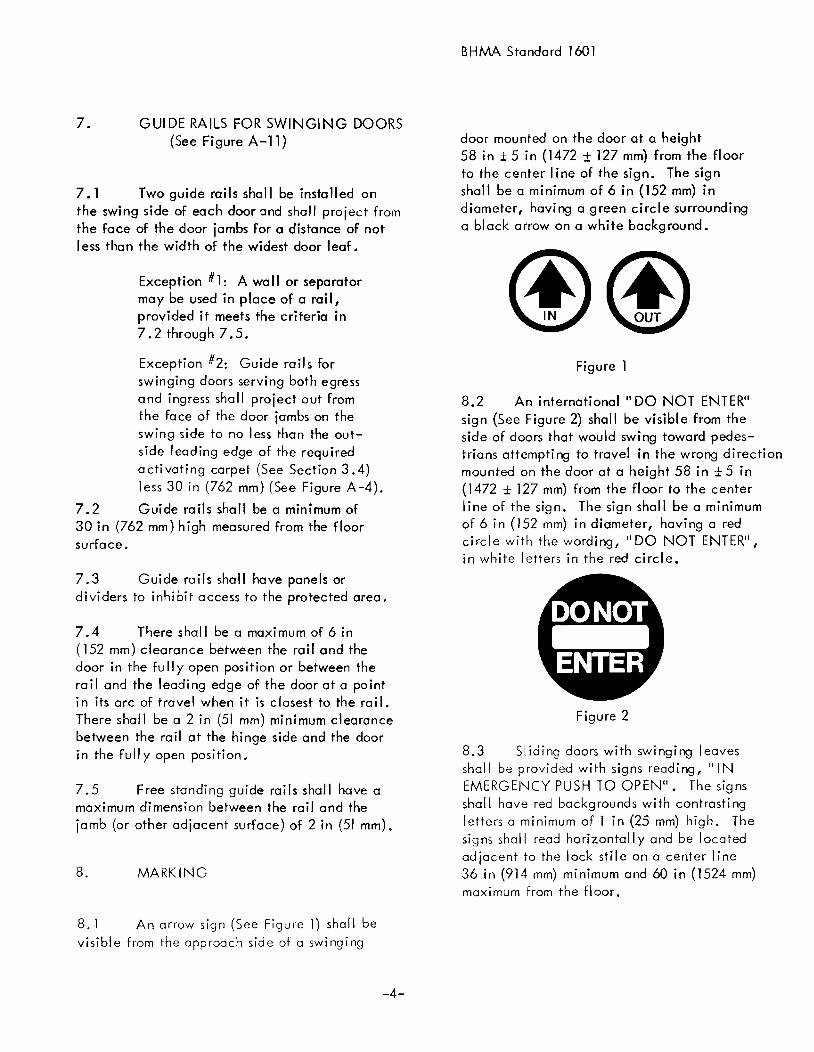
8.1 An arrow sign (See Figure 1) shall bevisible from the approach side of a swinging
-4-
BHMA Standard 1601
door mounted on the door at a height58 in ± 5 in (1472 ± 127 mm) from the floorto the center Iine of the sign. The signshall be a minimum of 6 in (152 mm) indiameter, having a green circle surroundinga black arrow on a white background.
Figure 1
8.2 An international" DO NOT ENTER"sign (See Figure 2) shall be visible from theside of doors that would swing toward pedestrians attempting to travel in the wrong directionmounted on the door at a height 58 in ± 5 in(1472 ± 127 mm) from the floor to the centerline of the sign. The sign shall be a minimumof 6 in (152 mm) in diameter, having a redcircle with the wording, "DO NOT ENTER",in white letters in the red circle.
Figure 2
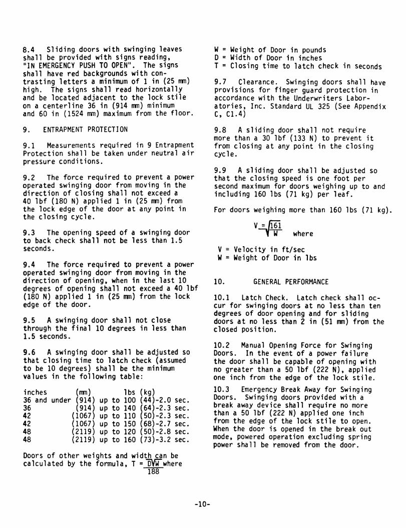
8.3 Sliding doors with swinging leavesshall be provided with signs reading, "INEMERGENCY PUSH TO OPEN". The signsshall have red backg rounds wi th contrasti ngletters a minimum of 1 in (25 mm) high. Thesigns shall read horizontally and be locatedad jacent to the lock sti Ie on a center line36 in (914 mm) minimum and 60 in (1524 mm)maximum from the floor.

8.4 Swinging doors serving both egressand ingress shall be marked with a decal,visible from both sides of the door, with thewords "Automatic Caution Door" (See Figure 3).The sign shall be mounted on the door at a height58 in ± 5 in (1472 ± 127 mm) from the floor to the
center! ine of the sign. The sign shall be aminimum of 6 in (152 mm) in diameter and madewith black lettering on yellow background.
Figure 3
9. REFERENCE TO OTHER STANDARDS
9. 1 See Appendix C for a reference toother Stundards affecting products describedin thi s Standard.
BHMA Standard 1601
10.5 A power operated swinging door shallnot close through the final 10 degrees in lessthan 1.5 seconds.
10.6 A swinging door shall be adjusted sothat the kinetic energy shall not exceed 2 1/2Ibf-ft. (3.4 Nm) at any point in its closingtravel. Closing time to latch - check (assumedto be 10 degrees) shall be adjustabl e to theminimum values in the following table:
36", up to 100 Ibs. - 1.9 sec.36", up to 140 Ibs. - 2.3 sec.42 ", up to 11 0 Ibs. - 2. 3 sec •42", up to 150 Ibs. - 2.7 sec.48", up to 120 Ibs. - 2.8 sec.48", up to 160 Ibs. - 3.2 sec.
Doors of other weights and width can be calculated by the formula, T = f5VW where
188
W = Weight of Door in poundsD = Width of Door in inchesT = Closing time to latch check in seconds
10. ENTRAPMENT PROTECTION
10.7 A sl iding door shall not require morethan a 30 Ibf (133 N) to prevent it fromclosing at any point in the closing cycle.
10. 1 Measurements required in 10 Entrap-ment Protection shall be taken under neutral airpressure conditions.
10.2 The force required to prevent a poweroperated swinging door from moving in thedirection of closing shall not exceed a 40 Ibf(180 N) applied 1 in (25 mm) from the lock edgeof the door at any point in the closing cycle.
10.3 The opening speed of a swinging doorto back check shall not be less than 1.25 sec.
10.4 The force required to prevent a poweroperated swi ngi ng door from movi ng in the direction of opening, when in the last 100 of openingshall not exceed a 40 Ibf (180 N) applied 1 in(25 mm) from the lock edge of the door.
-5-
10.8 A sliding door shall be adjusted sothat the kinetic energy shall not exceed 2 1/2Ibf-ft (3.4 Nm) at any point in the closingcycle. Closing speed shall be adjusted to onefoot per second maximum, or to the maximumvalues in the following table:
Door' eaf to:100 Ibs. - 1.27 ft/sec (0.79 sec/ft)120 Ibs. - 1.16 ft/sec (0.86 sec/ft)140 Ibs. - 1.07 ft/sec (0.93 sec/ft)160 Ibs. - 1 .00 ft/sec (1.00 sec/ft)
For doors weighing more than 160 Ibs.,
v =lfE-W
V = Velocity in ft/sec* W =Weight of Door in Ibs* For biparting doors, consider the weight of
one leaf.

10.9 Clearance: Swinging doors shallhave provisions for finger guard protection inaccordance with 25.12 of the UnderwritersLaboratories, Inc. Standard UL 325 (seeAppendix C, C 1.4).
11. GENERAL PERFORMANCE
BHMA Standard 1601
11 .6. 1 Doors with power operatorsshall be installed in a simulated wall and doorframing assembly of suffi dent strength to withstand all forces required by the tests. Installationshall be in accordance with the manufacturer'sprinted instructions. Maintenance and repair ofother than break away equipment may be performedduring the test cycles.
11.6.3 Cycle for 300,000 cycles ata rate of 5 to 8 per minute.
11.6.2 The test specimen shall be ofthe largest door size to be listed by the manufacturer.
11. 1 Latch Check: Latch check silo IIoccur for swinging doors at no less than tendegrees of door opening and for sliding doorsat no less than 2 inches from closed position.
11 .2 tv\anua I Openi ng Force forSwinging Doors: In the event of a powerfailure the door shall be capable of openingwith no greater than a 50 Ibf (222 N), appliedone inch from the edge of the lock stile.
11.6.4equipment shallduring the test.
Emergency break awaynot be Iubr icated or adj usted
12.2 Record the re Iease force prior toconducting the test. This shall not exceed a50 Ibf (222 N).
11.6.5 At every 50, 000 cycles duringthe test, swing out sections in sl iding doorsand emergency break outs in swinging doorssha II undergo 6, 000 cye! es wi thout fa i lure. Atthe conclusion of the test, break out forces shallnot exceed those listed in 11.4 and 11.5.
12.1 A sample of the latching and hingeassembl y of the break out mechanism of a poweroperated door contained in an approximately25 in (635 mm) wide panel shall be subjectedto a sal t fog test in accordance with ANSIZ118.1 (ASTM B-117) for 168 hours.
11.3* tv\anual Opening Force for SlidingDoors: In the event of a power failure the doorshall be capable of manual sl ide opening withno greater than a 50 Ibf (222 N).
11.4 Pani c Break Out for Swinging Doors:Swinging doors provided with panic break awayshall require no more than a 50 Ibf (222 N)appl ied one inch from the edge of the lock sti Ieto open. When door is opened in the panicbreak out mode, powered operation excludingspring power shall be removed from the door.
11.5* Panic Break Out for SI iding Doors:Sliding doors provided with panic break awayshall require no more than a 50 Ibf (222 N)appl ied at lock stile for the break away panelto open. When door is opened in the panicbreak out mode, powered operation exe! udingspring power shall be removed from the door(See Appendix C, C 1.3).
12. ** SALT SPRA Y TEST
*Where acceptable to the authorityhaving jurisdi ction, sliding doorswithout break out features may beused in non-hazardous areas withan occupancy of less than 50.
11.6** Emergency Egress Test for Swingingand Sliding Doors:
-6-
**These tests shall be performed underthe supervision of a certified testingagency on pre-production samplesprior to acceptance of the designfor production and subsequentinstallation.
12.3 At the conclusion of the exposuretime, remove the sample and allow to dry for24 hours without cleaning.
APPENDIX A
BHMA Standard 1601
12.4 Then cycle the sample 10 times. Therelease force for the first cycle shall not exceeda 100 Ibf (445 N). Rei ease forces for the next9 cycles shall not exceed a 50 Ibf (222 N).
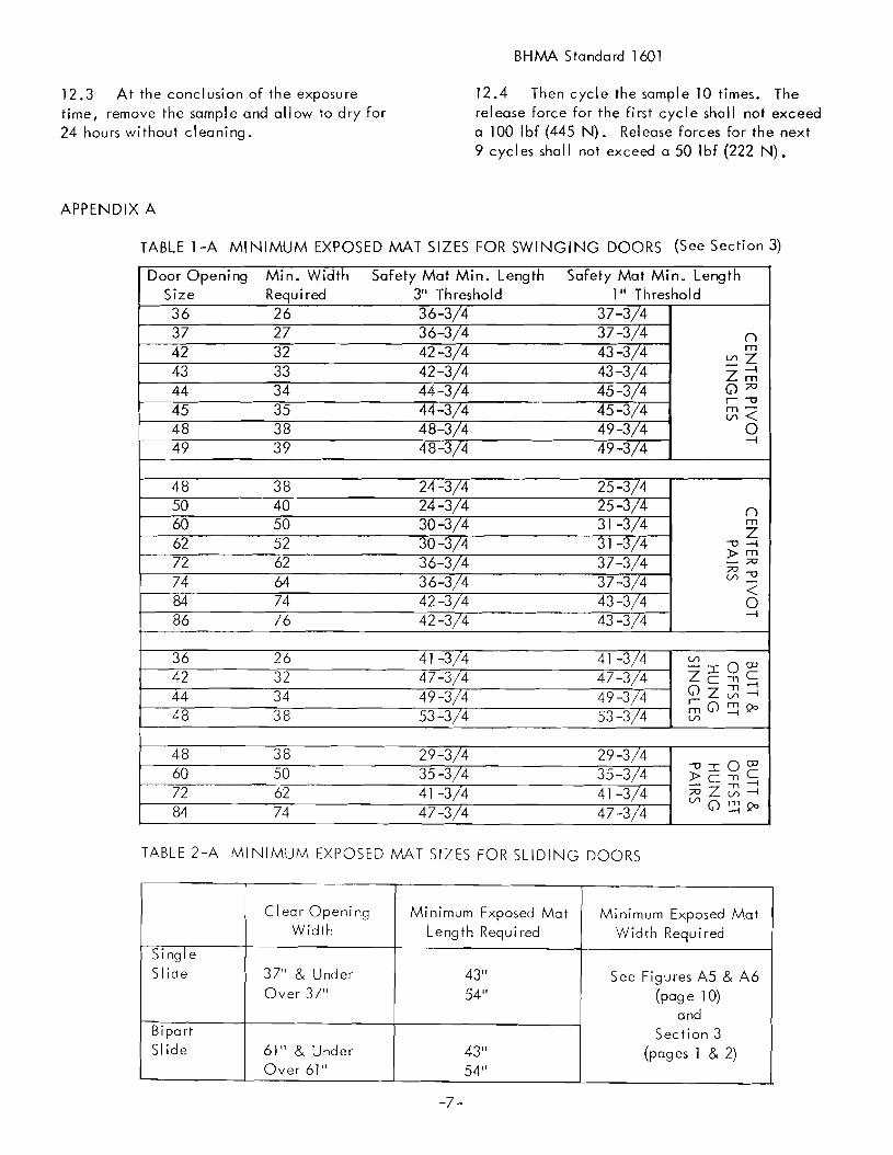
TABLE 1-A MI NIMUM EXPOSED MAT SIZES FOR SWI NGI NG DOORS (See Section 3)
Safety Mat Min. Length1" Threshold
Door OpeningSize3637424344454849
4850606272748486
36424448
48607284
Min. WidthRequired2627323334353839
3840505262647476
26323438
38506274
Safety Mat Min. Length3" Threshold36-3/436-3/442-3/442-3/444-3/444-3/448-3/448-3/4
24-3/424-3/430-3/430-3/436-3/436-3/442-3/442-3/4
41 -3/447-3/449-3/453-3/4
29-3/435-3/441 -3/447-3/4
37-3/437-3/443-3/443-3/445-3/445-3/449-3/449-3/4
25-3/425-J/431 -j/431-J/437-3/437-3/443-3/443-3/4
41 -3/447-3/449-3/453-3/4
29-3/435-3/441 -3/447-3/4
nm
V'lZZ~0;;0
r -umV'l<o
-l
nmZ
-0 -l»m- ;;0
~~<o-l
TABLE 2-A MINIMUM EXPOSED MAT SIZES FOR SLIDING DOORS
Clear Opening Minimum Exposed Mat Minimum Exposed MatWidth Length Required Width Required
SingleSlide 37" & Under 43" See Figures AS & A6
Over 37" 54" (page 10)and
Bi pa rt Section 3Slide 61" & Under 43" (pages 1 & 2)
Over 61" 54"
-7-

APPENDIX A (Continued) BHMA Standard 1601
CONTROL MAT LAYOUTS FOR SWINGI NG DOORS
Figure A-1(Ref. 3.2.1 and 3.3)
5"
Safety
Actuating
~----DoorOpening-------<~
L
Door Opening
<;Do
Y---r-r------,.".,."...-,---J]1- ~..___.,..",..._----.....,-+-J
MinimumReQ'd,
ExposedLength
L5"
SINGLE DOOR ON BUTTSOR OFFSET PIVOTS
PAIR OF DOORS ON BUTTSOR OFFSET PIVOTS
Door Openlng- I------Ooor Opening-------"
Figure A-2(Ref. 3.2.1 and 3.3)
2 3/.
- S" f--Mrn Req d --1 5 -- - 5' \---M,n, Req'd Exposed Wldth- 5' I--Exposed Width- f-f- 2 3;'"'_ I-l- -l- I--
I I Actuating I
[}+,Threshold
{] I -f}.r-Threshold
Mrnlmum
0Req'd
" 0a Exposed 0
Safety0
0 0
Length
4 ~5'
~
L5
fSINGLE DOOR ON23;' CENTER PIVOTS
PAIR OF DOORS ON2 3/. CENTER PIVOTS
-8-

APPENDIX A (Continued) BHMA Standard 1601
CONTROL MAT LAYOUTS FOR SWINGING DOORS
Figure A-3(Ref. 3.3)
3 3;'''
5"
(;oo
Safety
Min, Req'd, Exposed Width
(;o
J------Door Opening----~Door OPElninq----.~
'I*:=====:::::::::~~+--.------+ ~-1 I:===================~+
L5'"
L5"' 5'
SINGLE DOOR ON3 3;''' CENTER PIVOTS
PAIR OF DOORS ON3 34" CENTER PIVOTS
CONTROL MAT LAYOUT FOR TWO-WAY TRAFFIC SWINGING DOOR
Door Opening
Figure A-4(ref. 3.4)
T
- 5' f-- Min Reqd ,--j 5' _Exposed Width
Actuating
n -nb
(;
Safety0
"' Min.
I0" Min Actuating
-
5
10
j 30" Max
_~,---_~--L-9-

APPENDIX A (Continued) BHMA Standard 1601
CONTROL MAT LAYOUTS FOR SLIDING DOORS
Clear Opening
Figure A-5(Ref. 3.2.2)
Req'dLengttl
~ Door
m Req'd.ed Length
Width
- 5" f-- Min _ 5" --Req'd.Exposed
Width
.1Mlnlmu
ActuatingExpos
1/// Door
I I - Slide -JI II III / Minimum
II /Actuating Exposed
II.---/ Panic
U-- Breakaway
SINGLE SLIDING DOOR
Clear Opening Width-
- 5 'I------Min Req'd_ 5" --Exposed Width
IMinimu m Req'd
ActuatingExpos ed Length
JFigu re A-6(Ref. 3.2.2)
~V
Door Door g: Door~II - Slide - \ - Slide _
lilI I J I II I I I MinimuI I / \
m Req'd
Actuating I I Expos ed Length
II / ~I I
I I / Panic Panic ~ IIU-- Breakaway Breakaway ---LJ
BI-PARTING SLIDING DOOR
-10-

APPENDIX A (Continued) BHMA Standard 1601
CONTROL MAT CROSS SECTIONS
1.....------6" Max, Inactive Width------- ~I
a' .':',Jr';':'0 •• n '"
• D", '.' " ': LJ" ,fJ_,
(70"0",', ", ,~.;,l),: ~, • ~ ~: <, J, '.
Figure A-7(Ref. 3.6)
If -flII II
It ,II II Q ".
2Y;' Max, Inactive Area
When Mats ArePerpendicular To Opening
a c>.,c
Figure A-8(Ref. 3.5. 1)
n-- ----.-----
-fl
Q •
3 31." Max, Inactive AreaWhen Mats Are Parallel
To Opening
D''. • v"' -.J. , ~
o, ,f·• ".q.; ~-.•:
Figure A-9(Ref. 3.5.2)
Figure A-10(Ref. 3. 1, 3.7
and 4.5)
~Exposed Area l
1Y;' Max':-iInactive Area I
~~~e::::--...LL-__!:_l_____:_--L.L-D---o-,-,--o--,---,,.--,-,-\/I~~eACC~ "~a , 0 ~ D D () Q
• __ /J" 0 0 6 D "'A", ,,0 " !J <>" 0 - ,,() .. ~'.V '<J "r, ~. ~ ... A
Mat ThicknessY;' Max,
-11-

APPENDIX A (Continued) BHMA Standard 1601
GUIDE RAIL LAYOUTS FOR SWINGING DOORS
tApproach6" Max.
//
----Guide Rail
Figure A-II(Ref. 7.1 through 7.5)
Approach
Go;" R~f---6" Max.
Guide Rail
'·\:.7 /.'---
1'/
/11
0Iil; Door JD Door 0
Door Jamb Door Jamb
Panel OrDIvider
30" Min.
FREE STANDING FLOOR MOUNTED
"f-..--- Width Of Door ------<~Panel OrDivider
30" Min.
JAMB AND FLOOR MOUNTED
,,1---- Width Of Door ------<-
-12-
APPENDIX B
DEFINITIONS OF TERMS USED IN THE POWEROPERATED DOOR INDUSTRY
ACTIVE AREA. The sensitive portion of a matwhich detects presence.
ACTUATOR (or 0 PERATOR). The mechanicaldevice used to move (a) doors(s).
AIR LOC K. Air space between doors such as ina vestibule where ani y ane door or set of doorscan be opened at one time.
ALL GLASS DOOR. A door made from thickglass, usually heat treated, and having no metalstiles.
A PPROAC H BEAM. Photo-el ectric controlbeam used to actuate an automatic door.
APPROACH MAT. An actuating control matusually placed on the normal approach side ofa door causing the door to open when activated.
ARM. A device connecting the door operatofto the door. May be concealed, semi-concealedor surface applied.
AUTOMATIC DOOR. The combination of door,operator and controls constituting the system.
AUTOMATIC OPERATOR. (See AutomaticDoor Operator).
AUTOMATIC DOOR OPERATOR. A pONeroperated mechanism which is attached to a sliding or swinging or overhead door for the purposeof mechanically opening and closing a door uponthe receipt of an actuating signal.A door operating unit may be a gear driventransmission, pneumatic or hydraulic cylinder
mechanism and provides the basic opening andclosing forces for swinging or sliding doors.
-13-
BHMA Standard 1601
AUTOMATIC ENTRANCE PACKAGE. Complete entrance way containing doods), frame,controls, and automatic operator, unglazed.
BACK CHECK. The checking or slowing downof the speed of opening before being fully open.
BALANCED DOOR. A door equipped withdouble-pivoted hardware so designed as tocause a semi-counterbalanced swing actionwhen opening.
BI-PARTING SLIDING DOORS. A pair ofdoor leaves sliding away from each other toform a single comma" door opening.
BOTTOM ARM (Hardware). The arm mechanism attached to the bottam rai I of a door andconnecting to the spindle of a floor claser,pivot or automatic door operator ..
BREA KAWAY DEVICE. A device againstwhich a door stops in its normally closedposition but permits emergency egress swingof the door (opposite to normal swing) on "IN"doors where required by local codes. May beautomati call y or manual Iy reset and incorporates a switch to de-energize the operatorwhen in a panic position ..
BREA K OUT. The action of a sliding or swingingdoor when it is operated in the emergency mode.
Swinging or 51 iding doors which serve as exitdoors within a means of egress must be arrangedso that the door panel will swing in the directionof egress.
BREA K OUT OPENING. The clear space in adoorway when a swinging or 51 iding door isoperated in the emergency mode. This openingis not necessarily the same as the clear opening in the doorway when the door is operotedin the normal mode.

APPENDIX B (continued)
BREAK OUT SIDE. The side of the opening towhich the door swings when broken out.
CLEAR OPENING. The clear space in a doorway when the door is in the norma I open position.
CLOSING CYCLE. Movement of a swinging orsliding door from the fully open position tothe fully closed position.
CLOSING TIME. The element oftime fromthe starting of a door closing until it is atrest full y closed.
CONCEALED MOUNTING. Automatic dooroperators which are mounted above or belowthe door and power the door through the pivotor arm.
CONTROL. A unit containing electrical components for automatic control of door operationand overload protection.
CONTROL MAT. A deyice placed on thefloor in front of a doorway sensing the presenceof a person or object. It is normall y constructedof a rubber Iike material with a sl ip resistantsurface and is either recessed into or surfacemounted on d, e floor.
CONTROL MAT, ACTUATING. A controlmat which when activated Causes a door toopen.
CONTROL MA T, SAFETY. A control matwhich when activated prevents a door fromopen ing or hal ds a door open.
COORDINATOR. A mechanism which controls the order of closing of a pair of swingdoors, used with doors equipped with overlapping ostragals and certain panic hardware
which requires one door to ciose ahead of theother.
-14-
BHMA Standard 1601
COVER PLATE. In reference to door hardware, a finish plate used to cover the exposedface of a floor closer not covered by thethreshold; also a plate used to cover the ex
posed face of a closer or automatic dooroperator mounted in the head of a door frame.
CROSS BAR. The cross bar of a panic exitdevice, serving as a push bar to actuate thepanic hardware.
CYCLE. In this Standard, the action of anautomatic door operator starting with actuationthrough opening and full closing of (a) door(s).
DOOR. A movable barrier usually swingingor sl iding by which an entrance way is openedor closed.
DOOR ARM. A device which is usually locatedin the top or bottom rail of a swinging automaticdoor. The function of this device is to providesuitable connection of the automatic door operator to the door.
DOOR CLOSER. A mechanism to control theclosing of a door.
DOOR LIGHT. The glass area in a glazed door.
DOOR OPENING (See CLEAR OPENING).
DOOR SIZE (ACTUAL). For swinging or 51 iding doors, the actual width and height or thedoor leaf itself.
DOUBLE ACTING OPERATOR. An automaticdoor operator v'Ihich operates the door in either
direcrion from the closed position.
DOUBLE EGRESS. A double door configurationin which one leaf swings in and the other swingsout.
EGRESS. The act of leaving a building or room.

APPENDIX B (Continued
ELECTRIC LOCK. A locking device such asa deadlock which is extended and retracted byan electric impulse.
ELECTRIC SAFETY LOCK. A locking devicesimilar to an electric lock except with a powerfai lure, the bol t retracts automaticall y.
ELECTRIC STRIKE. A strike used with a lockand designed to be actuated by an electricremote control to permit a door to be openedwithout retracting the latch.
EMERGENCY BREA KAWA Y. See EMERGENCYRELEASE.
EMERGENCY RELEASE. A safety device otherthan an exit device which permits egress underemergency conditions.
ENTRANCE. A means of entering or leavinga building or room.
EXIT DEVICE. A door locking mechanism designed to be always operable from the egressside by pressure on a cross bar or paddle.
EXPOSED AREA. The visible area of a matafter the trim is installed.
FIN GER GUARD. A device appl ied at thehinge stile of a door or to the hinge jambadjacent to the door preventing damage tohands or fi ngers.
FIRE EXIT H.II.RDWARE. An exit devicelabeled for use on fire doors as well as listedfor panic.
FLOOR MAT. See CONTROL MAT.
FLOOR PIVOT. A center or offset pivotwhich is located at the floor or threshold.
-15-
BHMA Standard 1601
FLUSH BOLT. A rod or bolt mounted Rushwith the edge or face of the inactive leaf ofa pair of doors locking the door to the headeror the sill or threshold. Operation is usuallyby means of a recessed lever.
FLUSH GLAZING. A method of setting glasswhereby glazing beads are recessed and flushedwith the edge of the frame.
GUARD BAR. A protective bar applied to thelower portion of a door or sidelight to preventcall ision wi th the glass.
GUARD RAIL. See GUIDE RAIL.
GUIDE RAIL. A separator used with poweroperated doors for trafFic separation andcontrol.
HARNESS. A combination of wires andconnectors providing connection of electricalcontrols to operating equipment.
HINGE. Two metal plates having loops formedalong one edge of each to engage and rotateabout a common pivot rod or l1 p in ll used to
suspend a swinging door or window in itsframe. When both pi ates (or Ieaves) aremortised, it is sometimes called a butt hinge.
"IN" DOOR. An automatic door installationdesigned for traffic into a building, space,etc.
IN-HEADER 0 PER.II. TOR. A door operatorcompletely contained in the door headerrequiring only electric, pneumatic or hydraulic power.
KIC K PLATE. A plate appl ied to the face ofthe lower rail of a door or sidelight to protectagainst abrasion or impact loads or to maintain sight lines.

APPENDIX B (Continued)
KINETIC ENERGY. Energy resulting fromweight and speed of the door.
KNOWIN G ACT. With reference to the actof operating a door operator, such as pressing
a switch, and as opposed to Ilunknowing act. \I
LATCH CHECK. The checking or slowing downof the speed of closing before being fullyclosed.
LATCHING. Movement of a swinging orsliding door into the latched position.
LEFT HAND TRAFFIC. The traffic routingwhen the entrance door is placed to the leftof adjacent exit doors.
LINTEL. A horizontal structural memberspanning an opening at its head to carryconstruction above the opening.
LOCK. A hardware mechanism having a retractable bolt operated by a key, thumbturnor other means, and designed to hold a dooror window securel y closed.
MASONRY OPENING. The wall openinginto which the door is installed.
MEETING STILE. The vertical edge of a dooror window, in a pair, which is adjacent tothe other door or windaw. A parallel meetingstile is one which has a beveled edge paralleling the edge af the other door. A roundmeeting stile is ane having a rounded edge.
MOTION SENSOR. A device designed todetect the movement of a person or object inthe vicinity of the doorway and give an actuating signal to the operator.
OFFSET PIVOT. A pin-and-socket hingingdevice with a single bearing contact, tosuspend a door in its frame, allowing it toswing about an axis which is normally locatedabout 3/4" out from the door face.
-16-
BHMA Standard 1601
OPENING CYCLE. Movement of a swingingor sl iding door from closed door position tofully open. For swinging doors, this is normally 900.
"OUT" DOOR. An automatic door installation designed for traffic out of a building,space, etc ..
PAIRS. Two doors swinging in the somedirection with meeting lock stiles.
PANIC HARDWARE. See EXIT DEVICE.
PHOTO-CEll SYSTEM. A device employingthe use of visible or invisible beams and receivers across an opening. When a beam isinterrupted by a person or object, a signal isgenerated and used to activate or de-activatethe aperation of an automatic doar.
PHOTOELECTRIC CONTROL. A device whichemploys the use of a visible or invisible lightbeam across or through an apening. When theb~am is interrupted by a person or object, asignal is generated.
PIVOTED DOOR. A daar hung on pivots, asopposed to hinges.
POWER CLOSI NG. The closing of a door byenergy suppl ied from hydraul ics, pneumaticsor electricity.
POWER OPERATED DOOR. See AUTOMATICDOOR OPERATOR.
POWER OPEN. The opening af a door byenergy supplied by other than manual.
POWER UNIT. A remote mechanical deviceused to convert energ y (usual Iy e Iectri cal) topneumati c, hydrau Iic, or mechan ical energy fortransmission to the actuator.
PRESENCE SENSOR (See SENSING DEVICE).A device located in the vicinity of the doorwayta detect the presence of people ar abjects.

APPENDIX B (Continued)
PRESSURE RELIEF. A safety device to guardagainst excessive pressure bui Idup. Usuallywith reference to pneumatic or hydraulic
systems.
PULL CORD SWITCH. A switch locatedabove the doorway having a cord with handleextending down to approximately 6 feet abovethe Aoar • When the cord is pulled, a switchis closed and a signal generated which can beused to actuate an automatic door operator.
RAIL GUARD. See GUIDE RAIL.
RECESSED FRAME. A frame set into floorduring construction which secures mats intoframe to provide flush condition betweenfloor and mat surface.
RECYCLE. A mode of operation of an automatic door operator that occurs when the dooris in the closing portion of its travel and isactuated causing the door to immediatelyreverse and go to the open position.
RIGHT HAND TRAFFIC. The traffic routingwhen the entrance door is placed to the rightof adjacent exit doors.
SAFETY BEAM. See PHOTOELECTRICCONTROL.
SAFETY EDGE. A device applied to the edgeof a door, incorporating a switching deviceto stop or reverse its movement.
SAFETY MAT (See CONTROL MAT SAFETY).
SAFETY ZONE. The area on the swing sideof an automatic door installation which isprotected such that the door operator will not
operate when the area is occupied by personsor objects. The presence of the persons orobjects is sensed by actuating the mats,photoel ectric control s, presence sensors, etc.
-17-
BHMA Standard 1601
SELF-CONTAINED OPERATOR. An automaticoperator in which the actuator and the powerunit are made as a single unit.
SENSING DEVICE. A device that detectsthe motion or the presence of a person orobject •
SEQUENTIAL OR LATCHING OPERATION.Operation is push switch to actuate and pushswitch to deactuate.
SETTING BLOCKS. Small pieces of neoprene,lead or other material which are placed underthe lower edge of a sheet of glass ta supportit within a frame.
SETTING FRAME. A frame set into the floorto form a cavity for a control mat.
SHO P DRAWl N GS. Detai Ied drawings of aspecific job showing construction details,methods of assembly, and installation, plusall detai Is that will affect other constructionor trades.
SILL. The bottom horizontal member or surface of a door or window opening (the termis used incorrectly to refer ta a door threshold).
SINGLE ACTING OPERATOR. An automaticdoor operator which provides electrical, hydraulic, or pneumatic power to the door in theopening mode only. Return power is providedby spring action, gravity, weights, etc.
SINGLE SLIDE AUTOMATIC DOOR. An automatic door which has one sliding leaf, eitherleft hand or right hand.
SLA VE UNIT. A device that is controlled byanother device of the same function.
SLIDING DOOR. A single or pair of doorssliding parallel with the wall, or face of thebuilding.

APPENDIX B (Continued)
SLIDING, lEFT HAND AUTOMATIC DOOR.Automatic sliding doors are said to be leFthand when the door is viewed From the breakout side of the opening and it travels to theleFt of the viewer.
SLIDING RIGHT HAND AUTOMATIC DOOR.Automatic sl iding doors are said to be right·hand when the door is viewed From the breakout side of the opening and it travels to theright of the viewer.
SPRING CLOSING. The closing of a door byenergy supplied by springs.
STRIKE. An opening or retaining device provided in a Frame, threshold or in the edge of astile of an inactive door to receive a lock orlatch bolt. (Also referred to as a Keeper orStrike Plate.)
SURFACE BOLT. A rod or bol t mounted onthe Face of the inactive door of a pair tolock it to the frame or sill or both and operated manually.
SURFACE TRIM. See TRIM, MAT.
BHMA Standard 1601
perimeter of a control mat securing it to thefloor.
TRIM, RECESSED MAT. Material installedaround the perimeter of a control mat securingit recessed into the floor.
UNKNOWING ACT. Actuating a dooroperator, such as pressing a switch, withoutspecific knowledge of how it is done.
VARIABLE TIME DELAY. A device which maybe adjusted to change the time a door remainsopen, aFter removal of the open signal.
VISIBLE MOUNTING. Automatic dooroperators which are mounted above the door,protruding from the wall, and drive the doorwith a visible bracket and arm are said to bevisibly mounted.
Definitions for the following terms (and others)may be found in the American NationalStandard for Nomenclature for Steel Doorsand Steel Door Frames, ANSI A123.1-1974available from ANSI, 1430 Broadway, NewYork, New York 10018
SYNCHRON IZED 0 PERATORS. Operatorsconnected together either mechanically orelectrically for simultaneous operation.(Synonyms -- co-active, simultaneous)
THROW. The distance which a lock bolt orlatch bolt projects From the lock front when inthe locked position.
THUMBTURN. A lever which, when turned,operates the bolt of a lock.
TRAINED TRAFFIC. A controlled group ofpeople trained in the safe use and operationof a particular automatic door installation.
TRIM, MAT. Material installed around the
-18-
Active (door) leafAstragalCloser ReinforcementDoor Clearance
Door HandingRHlHRHRBlHRBPocket Door FrameDoor StopDouble SwingsDouble Acting DoorDouble Acting FrameDoubl e Egress FrameFrame
Hand of DoorsHeader Dr HeadInactive (door or) leafJambleaf (Door)MullionMuntinRailRevealSideliteSoffitStileSwing (see Door Handing)ThresholdTransom
Transom Bar
APPENDIX B (Continued)
SYMBOLS USED FOR POWER OPERATED SLIDING DOORS
TYPICAL DOOR ELEVATIONS
BHMA Standard 1601
p-x-x-p
LmJ', I, I, ,
KEY
x - Shdlng Panelo - Fixed $idehteP - Unit Without SideliteSO - SWing Out SideliteSX - SWing / Slide Panel
I----Width---I-~~T~Y~pe:..:o~-.2.x_=-------j~
Type o-SX
~I-----'-"~-~
-~=':::------ES
~ Type SO SX ~_ .~
~-------------:J -------
Type O/SO-SX
~~--- :J<~--~
Surf2.ce MOljnled
~~~ -~TypcP-Sx ~
For Letter Deslqna!lon Unlls Are ViewedFrom Exterior, l8ft To RighI.
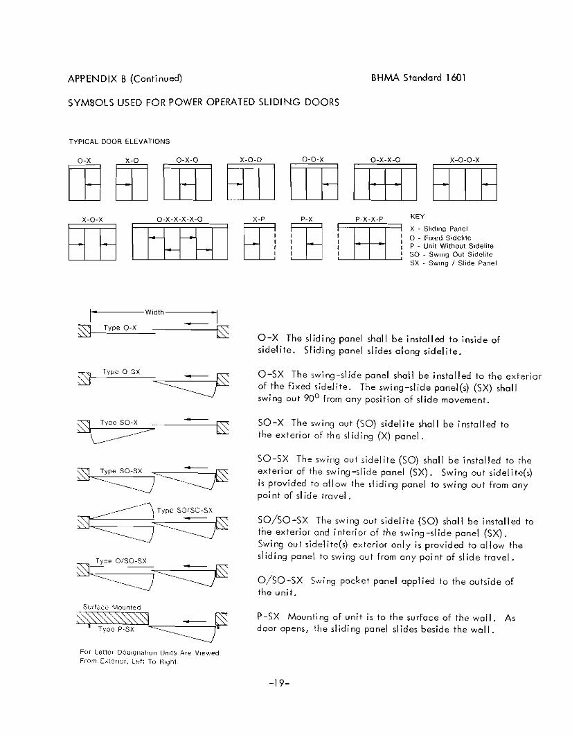
O-X The sliding panel shall be installed to inside ofsidelite. Sliding panel slides along sidelite.
O-SX The swing-slide panel shall be installed to the exteriorof the fixed sidelite. The swing-slide panel(s) (SX) shallswing out 90 0 from any position of slide movement.
SO-X The swing out (SO) sidelite shall be installed tothe exterior of the sliding (X) panel.
SO-SX The swing out sidelite (SO) shall be installed to theexterior of the swing-slide panel (SX). Swing out sidelite(s)is provided to allow the sliding ponel to swing out from onypoi nt of sl id e travel.
SO/SO-SX The swing out sidelite (SO) shall be installed tothe exterior and interior of the swing-slide panel (SX).Swing out sidelite(s) exterior only is provided to allow thesliding panel to swing out from any point of slide travel.
O/SO-SX Swing packet panel applied to the outside ofthe unit.
P-SX Mounting of unit is to the surface of the wall. Asdoor opens, the sliding panel slides beside the wall.
-19-
APPENDIX C
Cl REFERENCE TO OTHER STANDARDS
Cl • 1 When power operated fire doors areused, they may be subject to the requirementsof the Standard for Fire Doors and WindowsANSI/NFPA 80-1975. *
C1.2 Glazing in doors may be subject tocriteria in the Standard, PerformanceSpecifications and Methods of Test for SafetyGlazing Material Used in Buildings, ANSIZ97.1-1975. *
Cl.3 Where required by the authority havingjurisdiction, products meeting the re'1uirementsof the Standard may also be required to complywith Chapter 5, Means of Egress, of the Code forSafety to Life from Fire in Buildings andStructures. ANSI/NFPA 101-1976. *
CIA Where required by the authorityhaving jurisdiction, products meeting therequirements of this Standard may be requiredto compl y with U.L. 325** and be listed orlabeled by a nationally recognized testinglaboratory having a periodic examination service.
* Available from the American NationalStandards Institute, 1430 Broadway, New York,New York 10018
** Avoiloble from Underwriters Laboratories, Inc .•333 Pfingsten Road, Northbrook, IL 60062
-20-
BHM<\ Standard 1601

American National Standards
The standard in this booklet is one of over 11,000 standards approved todate by the American National Standards Institute, formerly the USAStandards Institute.
The Standards Institute provides the machinery for creating voluntarystandards. It serves to eliminate duplication of standards activities andto weld conflicting standards into single, nationally accepted standardsunder the designation, II American National Standards".
Each standard represents general agreement among maker, seller and usergroups as to the best current practice with regard to some specific problem. Thus, the completed standards cut across the whole fabric of production, distribution, and consumption of goods and services. AmericanNational Standards, by reason of Institute procedures, reflect a nationalconsensus of manufacturers, consumers and scientific, technical and professional organizations.
The Standards Institute, under whose auspices this work is being done, IS
the United States clearing house and coordinating body for standardsactivity on the national level. It is a federation of trade associations,technical societies, professional groups and consumer organizations. Some1,000 companies are affiliated with the Institute as company members.
The American National Standards Institute is the United States member ofthe International 0 rgani zati on for Standard izati on (I SO) and the International Electro-technical Commission (lEe). Through these channels,American industry makes its positionfelt on the international level. American National Standards are on file in the libraries of the national standardsbodies of more than 50 countries.
American National Standards Institute, Inc.
1430 Broadway New York, N.Y. 10018

ANSI/Bti'AA A156.10-1985
American National Standard
for power operated
pedestrian doors
american national standards institute, inc.1430 broadway, new york, new york 10018

ANSI/BHMA A156.10-1985Revision of:ANSI A156.10-1979
AMERICAN NATIONAL STANDARD
FOR
POWER OPERATED PEDESTRIAN DOORS
SPONSOR
BUILDERS HARDWARE MANUFACTURERS ASSOCIATION, INC.
APPROVED 25 APRIL 1985
AMERICAN NATIONAL STANDARDS INSTITUTE, INC.

AMERICAN NATIONAL STANDARD
An American National Standard implies a consensus of those substantially concerned with its scope and provisions. An AmericanNational Standard is intended as a guide to aid the manufacturer,the consumer and the general public. The existence of an AmericanNational Standard does not in any respect preclude anyone, whetherhe has approved the standard or not, from manufacturing, marketing,purchasing, or using products, processes, or procedures not conforming to the standard. American National Standards are subject toperiodic review and users are cautioned to obtain the latest editions.
CAUTION NOTICE: This American National Standard may be revised orwithdrawn at any time. The procedures of the American NationalStandards Institute require that action be taken to reaffirm, revise, or withdraw this standard no later than five years from thedate of publication. Purchasers of American National Standards mayreceive current information on all standards by calling or writingthe American National Standards Institute.
Published byBUILDERS HARDWARE MANUFACTURERS ASSOCIATION, INC.60 East 42nd Street New York, New York 10165
Copyright 1984 by the Builders Hardware Manufacturers Association, Inc.
Not to be reproduced without specific authorization from BHMA
Printed in the USA
lSM685/500
This Standard was approved by ANSI under the Canvass Method.BHMA was accredited on 21 March 1983 by ANSI as a sponsorusing the Canvass Method.
FOREWORD (This Foreword is not a part of ANSI/BHMA A156.10)
The general classification of builders hardwareincludes a wide variety of items which are divided into several categories. To recognizethis diversity, a sectional classification system has been established. Power Operated Doorsis one such section and this Standard is the resultof the collective efforts of members of the BuildersHardware Manufacturers Association , Inc. who manufacture this product. The total product standardseffort is, therefore, a collection of sections, eachcovering a specific category of items.
Performance tests, and, where necessary, dimensional requirements, have been established toinsure a degree of safety. There are no restrictionson design, except for those dimensional requirementsimposed for reasons of safety.
This Standard is not intended to obstruct, butrather to encourage, the development of improvedproducts, methods, and materials. The BHMA recognizes that errors will be found, items willbecome obsolete, and new products, methods, andmaterials will be developed. With this in mind,the Association plans to update, correct, andrevise these Standards on a regular basis. Itshall also be the responsibility of manufacturers to request such appropriate revisions.

CONTENTS SECTION
1. Genera1..... · · . · • · · • • · • • • • · · . · • • · • · · · · · · · · ·
2. Definitions ..........•••.•••............•..
3. Control Mats - Applications .......•.•......
4. Performance Requirements of Control Mats .
5. Sensing Devices - Applications .
6. Safety Zones - Applications....•.......•....
7. Guide Rails for Swinging Doors .
8. Marking .
9. Entrapment Protection..•...•.•............•.
10. General Performance••.•••••.•..•.....•..•.•.
11. Salt Spray Test ......••••••..•.....••.••••••
12. Testing Laboratory.•••.••••...••.•...•..••.•
Tables lA and 2A - Mat Sizes .....•..•.•....•.......•.••..
Appendix A - Illustrations .••.•....•..........•..•
Appendix B - Definitions ..•••••••.•.....•..••.•.••
Appendix C - Reference to Other Standards .•.•.•••.
PAGE
5
5 &6
6 &7
7 & 8
8
8
8 &9
9 & 10
10
10 &11
11
11
12
13 through 18
19 through 22
23

1. GENERAL
2.1 Active Area. The area where a mat orsensing device detects presence or motion.
1.2 This standard does not apply toPower Assist and Low Energy Power OperatedDoors covered in ANSI/BHMA A156.19.
2.2 Approach Mat. An actuating controlmat usually placed on the normal approachside of a door causing the door to openwhen activated.
2.3 Automatic Door Operator. A poweroperated mechanism which is attached to asliding or swinging door for the purposeof mechanically opening and closing a doorupon the receipt of an actuating signal.
2.4 Back Check. The checking or slowingdown of the speed of door opening beforebeing fully opened.
2.5 Break Away Device. A system which maybe a component or an integral part of apower operated sliding or swinging door permitting the door or a panel to swing in thedirection of egress when manual pressure isapplied.
2.9 Control Mat, Actuating. A controlmat which when activated causes a doorto open.
2.6 Break Out. The process of actuatinga break away device causing the door orpanel to swing in the direction of egress.
2.7 Closing Time. Time from starting of adoor closing until it is at rest fullyclosed.
2.8 Control Mat. A device placed onthe floor in front of a doorway sensingthe presence of a person or object. Itis normally constructed of a rubber likematerial with slip resistant surface andis either recessed into or surfacemounted on the floor.
2.10 Control Mat. Safety. A controlmat which when activated prevents adoor from opening or holds a door open.
2.11 Cycle. The action of an automaticdoor operator starting with actuationthrough opening and full closing of (a)door(s).
2.1~ Emergency Break Away. A safetydevlce other than an exit device whichpermits egress under emergency conditions.(Also called Emergency Release)
2.13 Exposed Area. The visible areaof a mat after the trim 1s installed.
DEFINITION OF TERMS USED IN THISSTANDARD
1.3 Required dimensions are expressed inUS units first and the SI (metric) equivalents given in parentheses are approximate.
1.4 American National Standards referenced in A156.10 are available from theAmerican National Standards Institute.1430 Broadway, New York, NY 10018. SeeAppendix C for a list of other standardsaffecting products described in ANSI/BHMAA156.10.
2.
1.1 Requirements for this Standard applyto power operated swinging and slidingdoors for pedestrian use and some smallvechicular traffic. Included are provisionsintended to reduce the chance of user injury or entrapment. Power operated doorsprimarily for industrial, vechicular ortrained traffic are not covered in thisStandard.
1.1.1 Where this Standard containsspecifications relating to minimum ormaximum dimensions of various componentsof power operated doors for pedestrian useand some small vechicular traffic, suchdimensions are included to provide userprotection for what are, in the industry,standard application conditions. ThisStandard does not attempt to assess anyfactors that may exist with respect tocustom design installations which mayormay not meet the requirements of thisStandard.
-5-

2.14 Finger Guard. A device appliedat the hinge stile of a door or to thehinge jamb adjacent to the door preventing damage to hands or fingers.
2.15 Guide Rail. A separator used withpower operated doors for traffic separationand control.
2.16 Latch Check. The checking orslowing down of the speed of closing adoor before being fully closed.
2.17 Motion Sensor. A device designedto detect the movement of a person or object in the vicinity of the doorway andgive an actuating signal to the operator.
2.18 Power Operated Door. The combination of door, operator and controls constituting the system. (Also called Automatic Door)
2.19 Presence Sensor. A device locatedin the vicinity of the doorway to detectthe presence of people or objects.
2.20 Safety Zone. An area protected suchthat the door operator will not operatewhen the area is occupied by persons orobjects moving or stationary.
2.21 Sensing Device. A device that detects the motion or presence of a personor object.
2.22 Trained Traffic. A controlledgroup of people trained in the safe useand operation of a particular automaticdoor installation.
2.23 Trim, Mat. Material installedaround the perimeter of a control matsecuring it to the floor.
2.24 See Appendix B for definitions ofother terms used in the power operateddoor industry, but not used in thisStandard.
3.2 Doors shall remain open for 1 1/2seconds minimum after loss of actuatingsignal.
3.3 Swinging Doors
3.3.1 The width of the exposed areaof an actuating or safety control matshall be the width of the door openingless a maximum of 5 in (127 mm) measuringfrom both sides for a total maximum of10 in (254 mm). (See Figures A-I, A-2, &A-3)
3.3.2 A safety zone shall be providedon the swing side of the door. If a safetycontrol mat is used, the length of theexposed area shall extend a minimum of5 in (127 mm) beyond the edge of the doorin the open position. (See Figures A-I,A-2, &A-3 and Section 6. )
3.3.3 Swinging doors serving bothegress and ingress shall have a series ofcontrol mats on the swing side of thedoor(s) consisting of a safety control matnearest the opening with a length of exposed area a minimum of 5 in (127 mm) beyond the edge of the door in the open position and one or more actuating controlmats totaling an additional 55 in (1397 mm)of exposed length. (See Exception #2 in7.1 and see Figure A-4)
3.4 Sliding Doors
3.4.1 The width of the exposed areaof an actuating mat shall be the clearopening width less a maximum of 5 in(I27 mm) measured from both sides for atotal maximum of 10 in (254 mm). (SeeFigures A-5 &A-6)
3.4.2 Sliding doors shall have anactuating control mat with a minimum exposed length according to Table 2-A.(See Figures A-5 & A-6)
3. CONTROL MATS - APPLICATIONS(See Tables I-A and 2-A)
3.5 Joining of Control Mats
3.1 The edge of the exposed area of allcontrol mats shall not exceed 1/2 in(13 mm) thickness. (See Figure A-10)
-6-
3.5.1 Control mats may be fitted sideby side with the longest dimension perpendicular to the opening and shall not havean inactive area of the meeting line exceeding 2 1/2 in (63 mm). (See Figure A-B)

3.5.2 Control mats may be fitted sideby side with the longest dimension parallelto the door opening and shall not have aninactive area at the meeting line exceeding3 3/4 in (95 mm). (See Figure A-g)
3.6 Controls mats meeting at a thresholdshall not have an inactive width exceeding6 in (152 mm) including threshold width.(See Figure A-7)
3.7 The active area of a control matshall be a maximum of 1 1/2 in (38 mm) fromany edge of the exposed area. (See FigureA-IO)
4. PERFORMANCE REQUIREMENTS OFCONTROL MATS
4.1 A control mat circuit shall operateat 30 volts rms or less.
4.2 Control mats shall be resistant towater, oil, grease and detergent.
4.3 Control Mat Sensitivity Test
4.3.1 Circuiting shall be activatedwhen a solid steel test disc 2.26 in(59 mm) in diameter is depressed with a25 lbf (Ill N) applied vertically, perpendicular to the disc in accordance with4.3.3 and 4.3.4, except that a 30 lbf(133 N) may be applied at the area of theelectrical contact connections and adjacent locations described in 4.3.3, ifnecessary.
4.3.2 The Control Mat shall be dividedinto 12 equal rectangles covering theactive area, except when the length of themat is such that the length of each rectangle would be greater than 12 in (300 mm)then the mat shall be divided into 15 or 18equal rectangles so that the length of eachrectangle is not less than 8 in ( 202 mm)nor more than 12 in (300 mm).
4.3.3 The test disc shall be placedin the approximate center of each interiorrectangle. For perimeter rectangles, placethe disc so that it abuts the edge of theactive area 1-1/2 in (38 mm) from the ex-
-7-
posed edge of the mat at the approximatecenterline of the rectangle. Compensatingfor the weight of the disc, apply a forceto activate the circuit. If the disc andforce fail to activate the Control Mat atany of the test locations, place the discon adjacent 90 degree tangents to testlocation(s) within the active area of themat. The disc must actuate the mat at alladjacent locations. Only one reading shallbe taken at each test location or adjacentlocations. If a check on the initialreading is desired, a period of at least 10minutes shall be allowed between readings.One test disc diameter shall be omittedfrom each corner of the mat when testing.The mats shall be tested on a flat, rigidsurface.
4.3.4 The test shall be conducted at68 degrees! 5 degrees F (20 degrees ! 2degrees C).
4.4 Control Mat Friction Test
4.4.1 A control mat shall have a coefficient of friction when dry and cleanof not less than .66 when tested in accordance with 4.4.2, 4.4.3, 4.4.4.
4.4.2 Coefficient of friction (M)shall be measured using a standard friction block (N) having a diameter of 4 in(102 mm), weighing 15 lbs (7 kg) andequipped with a neolite bottom 1/4 in(6 mm) thick.
4.4.3 The block shall be placed inthe middle of the mat with a linear scalecalibrated in pounds and kilograms attached.
4.4.4 Force required to just beginto move the block in any direction shallbe a minimum of 10 lbf (44 N) (F) applied1/2 in (13 mm) from the bottom of theblock.
4.4.5 The test shall be conductedin a room temperature of 68 degrees +5 degrees F (20 degrees ~ 2 degrees C).Mats shall be placed in the test room notless than 4 hours prior to the test.

4.4.6 The formula used for determiningthe coefficient of friction (M) shall beM= F where N = 15 lb weight (See 4.4.2) and
NF = 10 lbf minimum (See 4.4.4)
4.5 Control Mat Trim. Surface appliedcontrol mats shall be secured to the floorwith trim having a tapered leadup a minimumof 4 times the mat thickness at the exposededge. (See Figure A-I0)
5. SENSING DEVICES - APPLICATIONS(Also see 6)
5.1 Swinging Doors
5.1.1 Detection patterns shall begenerally eliptical and have a minimumwidth equal to the width of the dooropening measured 30 in (762 rom) from theface of the door. The length at thelongest dimension from the face of thedoor shall be 48 in (1219 mm) minimumDetection shall be effective to within5 in (127 mm) from the door measured atthe center of the door opening. (SeeFigure A-14)
5.1.2 The sensing device shall detectan object within the detection patternmeasuring 10 in (254 mm) wide t 6 in (152 mm)deep and 28 in (711 mm) high including a3 in (76 mm) radius top and moving at a rateof 6 in (152 mm) per second perpendicular tothe door for motion sensors and stationaryfor presence sensors. Actuation shall lastfor 1 1/2 seconds minimum after the objecthas left the pattern. The object shall bemade from solid pine or fir wood. Dimensionsgiven shall be ± 1/4 in (6 mm). (See FigureA-13)
5.2 Sliding Doors
5.2.1 Patterns and detection capabilitiesshall be in accordance with 5.1. The lengthat the longest dimension from the face ofthe door shall be 54 in (1372 mm) minimum.(See Figure A-12)
6. SAFETY ZONES FOR SWINGING DOORS APPLICATIONS
6.1 Asafety zone shall be provided onthe swing side of all power operatedswinging doors.
6.2 See 3.1 and 3.2 for requirements whenboth actuating and safety control mats areused in combination. (See Figure A-3)
6.3 If a sensing device is used foractivation and a safety control mat ;s usedas a safety zone, the active area of thesafety control mat shall extend a minimum of5 ;n (127 mm) beyond the edge of the doorin the open position and:
1) extend 5 in (127 mm) intothe approach area of the doormeasured from the face of thedoor; or2) the door opening area shallbe provided with a presencesensing device in accordancewith 5.2.2; or3) the door closing cycle shallhave a delay of 4 seconds minimumafter the actuating area is clear.
The width of a safety control mat shallbe in accordance with 3.2.1. (See Figure A-14)
6.4 If sensing devices are used toprovide a safety zone, the length of theactive area when the door is in the closedposition shall extend a minimum of 5 in(127 mm) beyond the edge of the door whenopen and the width of the active area whenthe door is in the open position shall bethe door opening less a maximum of 5 in(127 mm) measuring both sides for a totalmaximum of 10 in (254 mm).
6.5 If sensing devices are used to provideboth an actuation and a safety zone, any inactive width exceeding 6 in (152 mm) includingthreshold width shall:
1) be equipped with a safety controlmat; or2) equipped with a presence sensingdevice in accordance with 5.2.2; or3) have a door closing cycle delayof 4 seconds minimum after theactuation area is clear.
-8-
5.2.2 A presence sensing device shallbe located to detect an object as definedin 5.1.2 when the object is centered in thepath of a fully opened door.
7. GUIDE RAILS FOR SWINGING DOORS(See Figure A-II)

7.1 Two guide rails shall be installedon the swing side of each door and shallproject from the face of the door jambsfor a distance of not less than the widthof the widest door leaf.
Exception #1: A wall or separatormay be used in place of a rail, provided that it meets the criteria in7.2 through 7.5.
Exception #2: Guide rails forswinging doors serving both egressand ingress shall project out fromthe face of the door jambs on theswing side to no less than the outside leading edge of the requiredactivating carpet (See 3.2.4) less5 in (127 mm). (See Figure A-4)
7.2 Guide rails shall be a minimum of30 in (762 rnm) high measured from the floorsurface.
7.3 Guide rails shall have panels ordividers to inhibit access to the protectedarea.
7.4 There shall be a maximum of 6 in(152 mm) clearance between the rail andthe door in the fully open position orbetween the rail and the leading edge ofthe door at the point in its arc of travelwhen it is closest to the rail. Thereshall be a 2 in (51 mm) minimum clearancebetween the rail at the hinge side and thedoor in the fully open position.
7.5 Free standing guide rails shall havea maximum dimension between the rail andthe jamb (or other adjacent surface) of2 in (51 rom).
8. MARKING
8.1 An arrow sign (See Figure 1) shallbe visible from the approach side of aswinging door mounted on the door at aheight 58 in ± 5 in (1427 ± 127 mm) fromthe floor to the center line of the sign.The sign shall be a minimum of 6 in(152 mm) in diameter, having a green circlesurrounding a black arrow on a white background.
-9-
Figure 1
8.2 An international "00 NOT ENTER"sign (See Figure 2) shall be visible fromthe side of doors that would swing towardpedestrians attempting to travel in thewrong direction mounted on the door at aheight 58 in ± 5 in (1427 ± 127 mm) fromthe floor to the center line of the sign.The sign shall be a minimum of 6 in(152 mm) in diameter, having a red circlewi th the word i n9, .. DO NOT ENTER" J in whi teletters in the red circle.
DONOT
ENTERFigure 2
8.3 Swinging doors serving both egressand ingress shall be marked with a decal,visible form both sides of the door, withthe words IIAutomatic Caution Door" (SeeFigure 3). The sign shall be mounted onthe door at a height 58 in ± 5 in (1472 ±127 mm) from the floor to the centerlineof the sign. The sign shall be a minimumof 6 in (152 mm) in diameter and made withblack lettering on yellow background.
Figure 3
where
8.4 Sliding doors with swinging leavesshall be provided with signs reading,IIIN EMERGENCY PUSH TO OPEN II
• The signsshall have red backgrounds with contrasting letters a minimum of 1 in (25 mm)high. The signs shall read horizontallyand be located adjacent to the lock stileon a centerline 36 in (914 mm) minimumand 60 in (1524 mm) maximum from the floor.
9. ENTRAPMENT PROTECTION
9.1 Measurements required in 9 EntrapmentProtection shall be taken under neutral airpressure conditions.
9.2 The force required to prevent a poweroperated swinging door from moving in thedirection of closing shall not exceed a40 lbf (180 N) applied 1 in (25 mm) fromthe lock edge of the door at any point inthe closing cycle.
9.3 The opening speed of a swinging doorto back check shall not be less than 1.5seconds.
9.4 The force required to prevent a poweroperated swinging door from moving in thedirection of opening, when in the last 10degrees of opening shall not exceed a 40 lbf(180 N) applied 1 in (25 rnm) from the lockedge of the door.
9.5 A swinging door shall not closethrough the final 10 degrees in less than1.5 seconds.
9.6 A swinging door shall be adjusted sothat closing time to latch check (assumedto be 10 degrees) shall be the minimumvalues in the following table:
inches (mm) lbs (kg)36 and under (914) up to 100 (44)-2.0 sec.36 (914) up to 140 (64)-2.3 sec.42 (1067) up to 110 (50)-2.3 sec.42 (1067) up to 150 (68)-2.7 sec.48 (2119) up to 120 (50)-2.8 sec.48 (2119) up to 160 (73)-3.2 sec.
Doors of other weights and width can becalculated by the formula, T =DVWwhere
188
-10-
W= Weight of Door in poundso = Width of Door in inchesT = Closing time to latch check in seconds
9.7 Clearance. Swinging doors shall haveprovisions for finger guard protection ;naccordance with the Underwriters Laboratories, Inc. Standard UL 325 (See AppendixC, Cl.4)
9.8 A sliding door shall not requiremore than a 30 1bf (133 N) to prevent itfrom c10s;ng at any point in the c10s;ngcycle.
9.9 A sliding door shall be adjusted sothat the closing speed is one foot persecond maximum for doors weighing up to andincluding 160 lbs (71 kg) per leaf.
For doors weighing more than 160 lbs (71 kg).
V_~lP~l
v = Velocity in ft/secW= Weight of Door in lbs
10. GENERAL PERFORMANCE
10.1 Latch Check. Latch check shall occur for swinging doors at no less than tendegrees of door opening and for slidingdoors at no less than 2 in (51 mm) from theclosed position.
10.2 Manual Opening Force for SwingingDoors. In the event of a power failurethe door shall be capable of opening withno greater than a 50 lbf (222 N), appliedone inch from the edge of the lock stile.10.3 Emergency Break Away for SwingingDoors. Swinging doors provided with abreak away device shall require no morethan a 50 lbf (222 N) applied one inchfrom the edge of the lock stile to open.When the door is opened in the break outmode, powered operation excluding springpower shall be removed from the door.

11.2 Record the release force prior toconducting the test. This shall not exceed a 50 lbf (222 N).
12.1 Tests described in 10 and 11shall be performed under the supervisionof a nationally recognized independenttesting laboratory on pre-productionsamples prior to acceptance of the designfor production and subsequent installation. Production units shall be underan in-plant follow-up inspection service.
11.3 At the conclusion of the exposuretime, remove the sample and allow to dryfor 24 hours without cleaning.
11.4 Then cycle the sample 10 times.The release force for the first cycleshall not exceed a 100 lbf (445 N).Release forces for the next 9 cyclesshall not exceed a 50 lbf (222 N).
10.4 Emergency Break Out for SlidingDoors. Sliding doors provided with abreak away device shall require no morethan a 50 lbf (222 N) applied at the lockstile for the break out panel to open.Break away devices (swinging panels) fordoors tnat slide on the egress side of anopening may be equipped with a self closingdevice or cut off power to the operatorwhen used in the break out mode. Breakaway devices incorporating swing out sidelites shall cut off power to the operatorwhen used in the break out mode.(See Appendix C, C1.3)
10.5 Emergency Egress Test for Swingingand Sliding Doors.
10.5.1 Doors with power operatorsshall be installed in a simulated walland door framing assembly of sufficientstrength to withstand all forces requiredby the tests. Installation shall be inaccordance with manufacturer's printedinstructions. Maintenance and repair ofother than break away equipment may beperformed during the testing cycles.
10.5.2 The test specimen shall be ofthe largest door size to be listed by themanufacturer.
10.5.3 Cycle for 300,000 cycles at arate of 5 to 8 per minute.
10.5.4 Break away devices shall notbe lubricated or adjusted during the test.
10.5.5 At every 50,000 cycles duringthe test, sliding and swinging doorsshall undergo 6,000 break out cycleswithout failure. At the conclusion ofthe test, break out forces shall notexceed those listed in 10.3 and 10.4.
11. SALT SPRAY TEST
11.1 A sample of the latching andhinge assembly of the break away device of a power operated door containedin an approximately 25 in (635 mm) widepanel shall be subjected to a salt fogtest in accordance with ANSI Z118.l(ASTM 8-117) for 168 hours.
-11-
12. TESTING LABORATORY

TABLE I-A MINIMUM EXPOSED MAT SIZES FOR SWINGING DOORS (See 3.2.1 and 3.2.2)
Safety Mat Min. Length1" Threshold
Door Openi ngSize3637424344454849
4850606272748486
36424448
48607284
Min. WidthRequired2627323334J53839
3840505262647476
3438
38506274
Safety Mat Min. Length3" Threshold36-3/436-3/442-3/442-3/444-3/444-3/448-3/448-3/4
24-3/42 -3/430-3/430-3/436-3/436-3/442-3/442-3/4
41-3/447-3(449-3/453-3/4
29-3/435-3/441-3/447-3/4
37-3/437-3/443-37443-3/445-37445-3(449-37449-3/4
25-3/425-37431-3(431-3/437-37437-3/443-V4
41-37447-3,7449-3/453-3/4
29-3/435-3/441-3/447-3/4
()m
V'Z--4ZmG)~
r- ~m-V'<
o-4
()mZ
~ -t»m- ;0;0-0«.1\_
<o....
TABLE 2-A MINIMUM EXPOSED MAT SIZES FOR SLIDING DOORS
Clear Opening Minimum Exposed Mat Minimum Exposed MatWidth Length Required Width Required
SingleSlide 37" & Under 43" See Figures A5 & A6
Over 37" 54 11
andBiportSlide 61" & Under 43" 3.3. 1 and 3.3.2
Over 61" 54"
-12-

APPENDIX A {Not a part of ANSI/BHMA A156.10}
CONTROL MAT LAYOUTS FOR SWINGING DOORS
t---Door Opening- Door Opening
- S" I-::.Min. ReQ'd..-:- S" ~ - S" ~Min. Req'd. Exposed Width- S" 10-Exposed Width
Actuating
r ,Threshold
11 n.Threshold
flT· ..
Minimum
:s ReQ'd. :s :s0 Exposed 0 Safety0 0 CI
Length
L~ L JS" S" S", , t
Figure A-I{Ref. 3.2.1 and 3.2.2}
SINGLE DOOR ON BUTTSOR OFFSET PIVOTS
PAIR OF DOORS ON BUTTSOR OFFSET PIVOTS
Door Opening joe-----Door Openinll------o-l
Figure A-2{Ref. 3.2.1 and 3.2.2}
23,4"
R- S" I-::Min. eq'd.:-- S" - - S"~Min. Req'd. Exposed Width- s"~Exposed Width'- t-~ 23,4"- t- -I- ~
I I Actuating I
rThreshold.n n
,Threshold
u
fu
Minimum
:s Req'd. :s :s0 Exposed Safety
00 0
Length
L L --lS" S" S", , 1
2%'
SINGLE DOOR ON23,4" CENTER PIVOTS
PAIR OF DOORS ON23,4" CENTER PIVOTS
-13-

APPENDIX A (Continued)
CONTROL MAT LAYOUTS FOR SWINGING DOORS
......----Ooor Opening------!Door Opening
Min. Req'd.Exposed Width
Threshold
5"
3%"
Min. ReQ'd. Exposed Width
Actuating
Threshold
5"
3%"
(;c
MinimumReQ'd.
ExposedLength Safety
Figure A-3(Ref. 3.2.1 and 3.2.2)
L5"
L5"
SINGLE DOOR ON3%" CENTER PIVOTS
PAIR OF DOORS ON3%" CENTER PIVOTS
CONTROL MAT LAYOUT FOR TWO-WAY TRAFFIC SWINGING DOOR
Figure A-4(Ref. 3.2.4)
t--Door Opening-
- 5" I--- Min. Req'd ._ 5" "-Exposed Width
Actuating
n,Threshold
fI
(; Safety0c
-, Min.-- -
I Actuating, Min.
15" Max.
t-14-
5'
55'

APPENDIX A (Continued)
CONTROL MAT LAYOUTS FOR SLIDING DOORS
Clear Opening......--Width---;-.I
_5" _ Min. _ 5" '-
Req'd. r--Exposed
Width
Minimum Req'd.Exposed LengthActuating
1Minimum Req'd.
,--:~~~~~~~~&A:;C;;;;t;;;;u;;;;a~t;:in:;g~~.F7.~E~J~P~osed Length
~ Door , Door
II - Slide - /IIIIII IIIII /
/ PanicU-- Breakaway
SINGLE SLIDING DOOR
Figure A-5(Ref. 3.3.1 and 3.3.2)
......--Clear Opening Width-
- 5" .....--Min. Req'd. ---4001 5" _Exposed Width
1Minimum Req'd.
'/./j~~~~~~~&::;;;;;;;;;;;;;;A;;;;c;;;;t;:u;;;;a~t;;;;in;;;;g;;;;;;;;;;;;;:~k~~~~~~~./~E~~l~o:-sed Length
~ Door Door' Door
: : - Slide - / \ - Slide - :: 1: : / \ I I Minimum Req'd.
Actuating I I Exposed Length
II /.. " III I ..........: Panic Panic .......... ' IL1.- Breakaway Breakaway -.J..J
Figure A-6(Ref. 3.3.1 and 3.3.2)
BI-PARTING SLIDING DOOR
-15-

APPENDIX A (Continued)
CONTROL MATS CROSS SECTIONS
1...------ 6" Max. Inactive Width -------...,
Figure A-7(Ref. 3.6)
3%" Max. Inactive AreaWhen Mats Are Parallel
To Opening
nII
ItII
IIj
II
q. 0(J • " 4
2Y2" Max. Inactive AreaWhen Mats Are
Perpendicular To Opening
~... A. J • ~ •
... ~ .~.7:~ ~. ',> • :"
Mat ThicknessY2" Max.
-16-
Figure A-8(Ref. 3.4.1)
Figure A-9(Ref. 3.4.2)
Figure A-10(Ref. 3.1 9 3.6 and 4.5)

APPENDIX A (Continued)
GUIDE RAIL LAYOUTS FOR SWINGING DOORS
Figure A-ll(Ref. 7.1 through 7.5)
D
Rail
Approach
~6" Max.
Guide
/'---/
/
~'Door I
uide Rail f
D
Approach
+Guide Rai
Door
J
I
/~/
ide Rail
6" Max.-
o
...............""'- -6" Max.>-~ 2"Min.
Gu
JAMB AND FLOOR MOUNTED
Panel OrDivider
30" Min.
FREE STANDING FLOOR MOUNTED
, ...I----Width Of Door--..-lPanel OrDivider
30" Min.
__--Width Of Door----4.-l
-17-

APPENDIX A (Continued)
DETECTION PATTERN - SLIDING DOORS
Figure A-12(Ref. 5.2.1)
B
DETECTION PATTERN - SWINGING DOORS
Figure A-14(Ref. 5.1.1 and 6.3)
\\\\\\
A =54" Minimum LengthB =Clear Door Opening Width DETECTION
A AREA
SENSING DEVICE
1~Figure A-13(Ref. 5.1.2)
,I.
6"R I IL'I SAFETY MAT
I·Lij5"
6" 28" 10" t
A = 48" Minimum LengthB = Door Opening Width Measured
Jamb to Jamb at a point 30"from the face of the door.
-18-

APPENDIX B (Not a part of ANSI/BHMA A156.10)
DEFINITIONS OF TERMS AS USED IN THE POWEROPERATED DOOR INDUSTRY
Actuator (or Operator). The mechanicaldevice used to move (a) door(s).
Air Lock. Air space between doors such asin a vestibule where only one door or setof doors can be opened at one time.
Approach Beam. Photo-electric controlbeam used to actuate an automatic door.
Arm. A device connecting the door operatorto the door. May be concealed, semi-concealed or surface applied.
Automatic Door. The combination of door,operator and controls constituting thesystem.
Automatic Entrance Package. Completeentrance way containing door(s), frame,controls, and automatic operator, unglazed.
Balanced Door. A door equipped withdouble-pivoted hardware so designed as tocause a semi-counterbalanced swing actionwhen opening.
Bi-Parting Sliding Doors. A pair of doorleaves sliding away from each other toform a s;ngle common door opening.
Bottom Arm (Hardware). The arm mechanismattached to the bottom rail of a door andconnecting to the spindle of a floorcloser, pivot or automatic door operator.
Break Out Opening. The clear space in adoorway when a swinging or sliding door isoperated in the emergency mode. Thisopening is not necessarily the same asthe clear opening in the doorway when thedoor is operated in the normal mode.
Break Out Side. The side of the openingto which the door swings when broken out.
Clear Opening. The clear space in adoorway when the door is in the normalopen position.
Closing Cycle. Movement of a swinging orsliding door from the fully open positionto the fully closed position.
Concealed Mounting. Automatic door operators which are mounted above or below thedoor and power the door through the pivotor arm.
Control. A unit containing electrical compo~ents for automatic control of door operatl0n and overload protection.
Cover Plate. In reference to door hardware,a finish plate used to cover the exposedface of a floor closer not covered by thethreshold; also a plate used to cover theexposed face of a closer or automatic dooroperator mounted in the head of the doorframe.
Door Arm. A device which is usually located in the top or bottom rail of aswinging automatic door. The function ofthis device is to provide suitable connection of the automatic door operator tothe door.
Door Light. The glass area in a glazeddoor.
Do~r.Size (Actual). For swinging orsl,dlng doors, the actual width and heightof the door leaf itself.
Double Acting Operator. An automatic dooroperator which operates the door in eitherdirection from the closed position.
Flush Glazing. A method of setting glasswhereby glazing beads are recessed andflushed with the edge of the frame.
Guard Bar. A protective bar applied tothe lower portion of a door or sidelightto prevent collision with the glass.
Harness. A combination of wires and connectors providing connection of electricalcontrols to operating equipment.
-19-
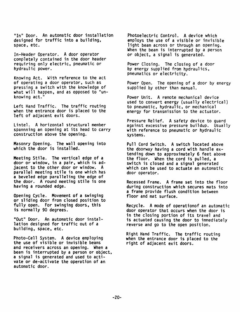
IIIn ll Door. An automatic door installationdesigned for traffic into a building,space, etc.
In-Header Operator. A door operatorcompletely contained in the door headerrequiring only electric, pneumatic orhydraulic power.
Knowing Act. With reference to the actof operating a door operator, such aspressing a switch with the knowledge ofwhat will happen, and as opposed to "unknowing act."
Left Hand Traffic. The traffic routingwhen the entrance door is placed to theleft of adjacent exit doors.
Lintel. A horizontal structural memberspannning an opening at its head to carryconstruction above the opening.
Masonry Opening. The wall opening intowhich the door ;s installed.
Meeting Stile. The vertical edge of adoor or window, in a pair, which is adjacent to the other door or window. Aparallel meeting stile is one which hasa beveled edge paralleling the edge ofthe door. A round meeting stile is onehaving a rounded edge.
Opening Cycle. Movement of a swingingor sliding door from closed position tofully open. For swinging doors, thisis normally 90 degrees.
"Out ll Door. An automatic door installation designed for traffic out of abuilding, space, etc.
Photo-Cell System. A device employingthe use of visible or invisible beamsand receivers across an opening. When abeam is interrupted by a person or object,a signal is generated and used to activate or de-activate the operation of anautomatic door.
-20-
Photoelectric Control. A device whichemploys the use of a visible or invisiblelight beam across or through an opening.When the beam is interrupted by a personor object, a signal is generated.
Power Closing. The closing of a doorby energy supplied from hydraulics,pneumatics or electricity.
Power Open. The opening of a door by energysupplied by other than manual.
Power Unit. A remote mechanical deviceused to convert energy (usually electrical)to pneumatic, hydraulic, or mechanicalenergy for transmission to the actuator.
Pressure Relief. A safety device to guardagainst excessive pressure buildup. Usuallywith reference to pneumatic or hydraulicsystems.
Pull Cord Switch. A switch located abovethe doorway having a cord with handle extending down to approximately 6 feet abovethe floor. When the cord is pulled, aswitch is closed and a signal generatedwhich can be used to actuate an automaticdoor operator.
Recessed Frame. A frame set into the floorduring construction which secures mats intoa frame provide flush condition betweenfloor and mat surface.
Recycle. A mode of operationof an automaticdoor operator that occurs when the door isin the closing portion of its travel andis actuated causing the door to immediatelyreverse and go to the open position.
Right Hand Traffic. The traffic routingwhen the entrance door is placed to theright of adjacent exit doors.

Self-Contained Operator. An automaticoperator in which the actuator and thepower unit are made as a single unit.
Sequential or Latching Operation.Operation of push switch to actuateand push switch to deactuate.
Setting Blocks. Small pieces of neoprene,lead or other material which are placedunder the lower edge of a sheet of glassto support it within a frame.
Setting Frame. A frame set into the floorto form a cavity for a control mat.
Single Acting Operator. An automatic dooroperator which provides electrical, hydraulic, or pneumatic power to the doorin the opening mode only. Return poweris provided by spring action, gravity,weights, etc.
Single Slide Automatic Door. An automaticdoor which has one sliding leaf, eitherleft hand or right hand.
Slave Unit. A device that is controlledby another device of the same function.
Sliding Left Hand Automatic Door. Automatic sliding doors are said to be lefthand when the door is viewed from thebreak out side of the opening and it travels to the left side of the viewer.
Sliding Right Hand Automatic Door. Automatic sliding doors are said to be righthand when the door is viewed from thebreak out side of the opening and it travels to the right side of the viewer.
Spring Closing. The closing of a door byenergy supplied by springs.
Strike. An opening or retaining deviceprovided in a frame, threshold or in theedge of a stile of an in active door toreceive a lock or latch bolt. (Also referred to as a Keeper or Strike Plate).
Synchronized Operators. Operators connected together either mechanically orelectrically for simultaneous operation.(Synonyms --co-active t simultaneous)
-21-
Trim, Recessed Mat. Material installedaround the perimeter of a control matsecuring it recessed into the floor.
Unknowing Act. Actuating a door operator t
such as pressing a switch, without specific knowledge of how it is done or whatwill happen.
Variable Time Delay. Adevice which maybe adjusted to change the time a door remains open, after removal of the opensignal.
Visible Mounting. Automatic door operators which are mounted above the door,protruding from the wall t and drive thedoor with a visible bracket and arm aresaid to be visibly mounted.
Definitions of other terms may be found inthe American National Standard for Nomenclature for Steel Doors and Steel DoorFrames t ANSI A123.1 and in the other ANSI/BHMA A156 Series of Standards.

APPENDIX B (Continued)
SYMBOLS USED FOR POWER OPERATED SLIDING DOORS
TYPICAL DOOR ELEVATIONS
KEYp-x-x·p
CEEJ X - Sliding PanelI I O. Fixed Sidelite: : P - Unit Without Side liteI I SO - Swing Out Sidelite
SX - Swing / Slide Panel
ra En em [!] ern cmJ a::rntr8 rnllrJ tIJ rn
I.....>-----Width-----.,
~ Type O·X --- ~o-X The sliding panel sholl be installed to inside ofsidelite. Sliding panel slides along sidelite.
~I--T...:y.:..pe......;;.o-..;;s--x-~ o-SX The swing-slide panel sholl be installed to the exteriorof the fixed sidelite. The swing-slide ponel{s) (SX) shollswing out 900 from any position of slide movement.
SO-X The swing out (SO) sidelite sholl be installed tothe exterior of the sliding (X) panel.
~~~
~~
SO-SX The swing out sidelite (SO) sholl be installed to theexterior of the swing-slide panel (SX). Swing out sidelite{s)is provided to allow the sliding panel to swing out from anypoi nt of sl ide travel.
SO/SO-SX The swing out sidelite (SO) sholl be installed tothe exterior and interior of the swing-slide panel (SX).Swing out sidelite(s) exterior only is provided to allow thesliding panel to swing out from any point of slide travel.
O/SO-SX Swing pocket panel applied to the outside ofthe unit.
Surface Mounfed
~~~ ---~TypeP·Sx~
For Letter Designation Units Are ViewedFrom Exterior, Left To Right.
P-SX Mounting of unit is to the surface of the wall. Asdoor opens, the sliding panel slides beside the wall.
-22-

APPENDIX C (Not a part of ANSI/BHMA A156.10)
C1 REFERENCE TO OTHER STANDARDS
Cl.! When power operated fire doors areused, they may be subject to the requirements of the Standard for Fire Doors andWindows ANSI/NFPA 80.*
C1.2 Glazing in doors may be subjectto criteria in the Standard, PerformanceSpecifications and Methods of Test forSafety Glazing Material Used in Buildings,ANSI Z97.1.*
Cl.3 Where required by the authority havingjurisdiction, products meeting the requirements of this Standard may also be requiredto comply with Chapter 5, Means of Egress,of the Code for Safety from Fire inBuildings and Structures. ANSI/NFPA 101.*
C1.4 Where required by the authorityhaving jurisdiction, products meetingthe requirements of the Standard may berequired to comply with UL 325** and belisted or labeled by a nationally recognized independent testing laboratoryhaving periodic examination service.
Cl.5 Products meeting the requirementsof this Standard shall also comply withapplicable local building code requirements.
* Available from the American NationalStandards Institute, Inc., 1430 Broadway,New York, New York 10018.
**Available from Underwriters laboratories,Inc., 333 Pfingsten Road, Northbrook, IL60662.
-23-

American National Standards
The standard in this booklet is one of over 11,000 standards approved todate by the American National Standards Institute, formerly the USAStandards Institute.
The Standards Institute provides the machinery for creating voluntarystandards. It serves to eliminate duplication of standards activities andto weld conflicting standards into single, nationally accepted standardsunder the designation, .. American National Standards".
Each standard represents general agreement among maker, seller and usergroups as to the best current practice with regard to some specific problem. Thus, the completed standards cut across the whole fabric of production, distribution, and consumption of goods and services. AmericanNational Stardards, by reason of Institute procedures, reflect a nationalconsensus of manufacturers, consumers and scientific, technical and professional organizations.
The Standards Institute, under whose auspices this work is being done, isthe United States clearing house and coordinating body for standardsactivity on the national level. It is a federation of trade associations,technical societies, professional groups and consumer organizations. Some1,000 companies are affiliated with the Institute as company members.
The American National Standards Institute is the United States member ofthe International Organization for Standardization (ISO) and the International Electro-technical Commission (lEe). Through these channels,American industry makes its positionfelt on the international level. American National Standards are on file in the libraries of the national standardsbodies of more than 50 countries.
Americ.n N.tlon81 St.net.rds Inltitute, Inc.
1430 BrC*tw8Y New York, N.Y. 10018
ANSI/BHMA A156.10-1991
American National Standard
for power operated
pedestrian doors
~~ ..~."~I
American National Standards Institute11 West 42nd Street, New York, NY 10036
otaCDS»~11OQaof:
III11CD
R1
tn
in....PI........rt....CDI'D
ANSI/BHMA AI56.10-1991Revision of:
ANSI AI56.10-1985
AMERICAN NATIONAL STANDARD
FOR
POWER OPERATED PEDESTRIAN DOORS
SPONSOR
BUILDERS HARDWARE MANUFACTURERS ASSOCIATION, INC.
Approved 10 September 1991
AMERICAN NATIONAL STANDARDS INSTITUTE, INC.

AMERICAN NATIONAL STANDARD
An American National Standard implies a consensus of thosesubstantially concerned with its scope and provisions. AnAmerican National Standard is intended as a guide to aid themanufacturer, the consumer and the general public. The" existenceof an American National Standard does not in any respect precludeanyone, whether he has approved the standard or not, from manufacturing, marketing, purchasing, or using products, processes,or procedures not conforming to this standard. American NationalStandards are subject to periodic review and users are cautionedto obtain the latest editions.
CAUTION NOTICE; This American National Standard may be revisedor withdrawn at any time. The procedures of the AmericanNational Standards Insti tute require that action be taken toreaffirm, revise, or withdraw this standard no later than fiveyears from the date of publication. Purchasers of AmericanNational Standards may receive current information on allstandards by calling or writing the American National StandardsInstitute.
Published byBUILDERS HARDWARE MANUFACTURERS ASSOCIATION, INC.355 Lexington Avenue New York, New York 10017
Copyright 1991 by theBuilders Hardware Manufacturers Association, Inc.
Not to be reproduced without specific authorization from BHMA
Printed in the USA
10Ml191/800
This Standard was approved by ANSI under the Canvass Method.BHMA was accredited on 21 March 1983 by ANSI as a sponsorusing the Canvass Method.

FOREWORD (This Foreword is not a part of ANSI/BHMA A156.10)
The general classification of builders hardwareincludes a wide variety of items which are dividedinto several categories. To recognize thisdiversity, a sectional classification system hasbeen established. Power Operated Doors is onesuch section and this Standard is a result of thecollective efforts of members of the BuildersHardware Manufacturers Association, Inc. whomanufacture this product. The total ProductStandards effort is, therefore, a collection ofsections, each covering a specific category ofitems.
Performance tests and, where necessary,dimensional requirements have been established toinsure a degree of safety. There are norestrictions on design except for thosedimensional requirements imposed for reasons ofsafety.
This Standard is not intended to obstruct butrather to encourage the development of improvedproducts, methods and materials. The BHMArecognizes that errors will be found, items willbecome obsolete, and new products, methods andmaterials will be developed. With this in mind,the Association plans to update, correct andrevise these Standards on a regular basis. Itshall also be the responsibility of manufacturersto request such appropriate revisions.

SECTION
2. Definitions •••••••••••••••••••••
1. General •••••••••••••••••••••••••
10. General Performance •••••••••••••
PAGE
5
5 & 6
6 & 7
7 & 8
8
8 & 9
9 & 10
10
11
11 & 12
12
12
13
14 through 19
20 through 23
24
24
Control Mats - Applications
4. Performance Requirements ofControl Mats ••••••••••••••••••••
5. Sensing Devices - Applications ••
7. Guide Rails for Swinging Doors ••
8 • Ma rki ng •••••••••••••••••••••••••
9. Entrapment Protection •••••••••••
3.
6. Safety Zones - Applications •••••
Appendix B - Definitions •••••••••••••
Appendix A - Illustrations •••••••••••
Appendix C - Reference to OtherStandards •••••••••••••••
Appendix D - Conformance, Packagingand Marking •••••••••••••
12. Testing Laboratory ••••••••••••••
Tables lA and 2A - Mat Sizes •••••••••
11. Salt Spray Test •••••••••••••••••
CONTENTS

1. GENERAL
1.1 Requirements in this Standardapply to power operated swingingand sliding doors for pedestrianuse and some small vehiculartraffic. Included are provisionsto reduce the chance of user injuryor entrapment. Power operateddoors for industrial, vehicular ortrained traffic are not covered inthis Standard.
1.1.1 Where this Standardcontains specifications relating tominimum or maximum dimensions ofvarious components of poweroperated doors for pedestrian useand some small vehicular traffic,such dimensions are included toprovide user protection for whatare, in the industry, standardapplication conditions. ThisStandard does not attempt to assessany factors that exist with respectto custom design installations.
1. 2 This Standard does not applyto power assist and low energypower operated doors in ANSI/BHMAA156.19 for Power Assist and LowEnergy Power Operated Doors.
control mat usually placed on thenormal approach side of a doorcausing the door to open whenactivated.
2.3 Automatic Door Operator. Apower operated mechanism which isattached to a sliding or swingingdoor for the purpose of mechanically opening and closing a door uponthe receipt of an actuating signal.
2 • 4 Back Check. The checking orslowing down of the speed of dooropening before being fully opened.
2. 5 Break Away Device. A systemwhich is either a component or anintegral part of a power operatedsliding or swinging door permittingthe door or a panel to swing in thedirection of egress when manualpressure is applied.
2.6 Break Out. The process ofactivating a break away devicecausing the door or panel to swingin the direction of egress.
2. 7 Closing Time. Time fromstarting of a door closing until itis at rest fully closed.
2. DEFINITION OF TERMS USED INTHIS STANDARD
1.3 Required dimensions areexpressed in US units first and theSI (metric) equivalents given inparentheses are approximate.
1.4 American National Standardsreferenced in A156.10 are availablefrom the American NationalStandards Institute, 11 West 42ndStreet, New York, NY 10036. ASTMStandards referenced in A156.10 areavailable from ASTM, 1916 RaceStreet, Philadelphia, PA 19103(also see Appendix C)
2.1 Active Area.mat or sensingpresence or motion.
Emergency Break Away. Adevice other than an exit
2.12Safety
2.11 Cycle. The action of anautomatic door operator startingwith activation through opening andfull closing of (a) door(s).
2.8 Control Mat. A device placedon the floor in front of a doorwaysensing the presence of a person orobject. It is normally constructedof a rubber like material with slipresistant surface and is eitherrecessed into or surface mounted onthe floor.
2.10 Control Mat, Safety. Acontrol mat which when activatedprevents a door from opening orholds a door open.
2.9 Control Mat, Activating. Acontrol mat which Ylhen activatedcauses a door to open.
An activating
The area where adevice detects
Mat.Approach2.2
-5-
2 .14 Finger Guard. A deviceapplied at the hinge stile of adoor or to the hinge jamb adjacentto the door preventing damage tohands or fingers.
egress under(Also called
2.24 See Appendix B for definitions of other terms used in thepower operated door industry, butnot used in this Standard.
3.1 The edge of the exposed areaof all control mats shall notexceed 1/2 in (13 rom) thickness.(See Figure A-IO)
CONTROL MATS - APPLICATIONS(See Tables I-A and 2-A)
3 •
visibletrim is
Thethe
2.13 Exposed Area.area of a mat afterinstalled.
device which permi tsemergency conditions.Emergency Release)
2.15 Guide Rail. A separator usedwi th power operated doors fortraffic separation and control.
3 • 2 Doors shall remain open for1 1/2 seconds minimum after loss ofactuating signal.
2.16 Latch Check. The checking orslowing down of the speed ofclosing a door before being fullyclosed.
2.17 Motion Sensor. A devicedesigned to detect the movement ofa person or object in the vicinityof the doorway and give anactivating signal to the operator.
3.3 Swinging Doors
3.3.1 The width of the exposedarea of an activating or safetycontrol mat shall be the width ofthe door opening less a maximum of5 in (127 mm) measuring from bothsides for a total maximum of 10 in(254 mm). (see Figures A-I, A-2, &
A-3)
2.18 Power Operated Door. Thecombination of door, operator andcontrols constituting the system.(Also called Automatic Door)
2.19 Presence Sensor. A devicelocated in the vicinity of thedoorway to dete.ct the presence ofpeople or objects.
3.3.2 A safety zone shall beprovided on the swing side of thedoor. If a safety control mat isused, the length 0 f the exposedarea shall extend a minimum of 5 in(127 mm) beyond the edge 0 f thedoor in the open position. (seeFigures A-I, A-2, & A-3 and Section6 • )
2.20 Safety Zone. An area protected such that the door operatorshall not operate when the area isoccupied by persons or objectsmoving or stationary.
2.21 Sensing Device. A devicethat detects the motion or presenceof a person or object.
2.22 Trained Traffic. A controled group of people trained in thesafe use and operation of a particular automatic door installation.
2.23 Trim, Mat. Materialinstalled around the perimeter of acontrol mat securing it to thefloor.
3.3.3 Swinging doors servingboth egress and ingress shall havea series of control mats on theswing side 0 f the door (s )consisting of a safety control matnearest the opening wi th a lengthof exposed area a minimum of 5 in(127 nun) beyond the edge 0 f thedoor in the open posi tion and oneor more activating control matstotaling an additional 55 in (1397mm) of exposed length. (see exception #2 in 7.1 and see Figure A-4)
3.4 Sliding Doors
3.4.1 The width of the exposedarea of an activating mat shall bethe clear opening width less a
-6-

3.5 Joining of Control Mats
4.3 Control Mat Sensitivity Test
4. PERFORMANCE REQUIREMENTS OFCONTROL MATS
4.1 A control mat circuit shalloperate at 30 volts rms or less.
4.3.3 The test disc shall beplaced in the approximate center ofeach interior rectangle. Forperimeter rectangles, place thedisc so that it abuts the edge ofthe active area 1 1/2 in (38 rom)from the exposed edge of the mat atthe approximate center line of therectangle. Compensating for theweight of the disc, apply a forceto activate the circuit and take asingle reading. If the disc andforce fail to activate the ControlMat at any of the test locations,place the disc on adjacent 90degree tangents to the testlocation(s) within the active areaof the mat. The disc shall activatethe mat at all adjacent locations.If a check on the initial readingis desired, a period of at least 10minutes shall be allowed betweenreadings. One test disc diametershall be ami tted from each cornerof the mat when testing. The matsshall be tested on a flat, rigidsurface.
4.3.4 The test shall be conducted at 68 degrees + 5 degrees F (20degrees + 2 degrees C).
4.4 Control Mat Friction Test
4.4.1 A control mat shall have acoefficient of friction when dryand clean of not less than .66 whentested in accordance with 4.4.2,4.4.3, and 4.4.4.
4.3.2 The Control Mat shall bedivided into 12 equal rectanglescovering the active area, exceptwhen the length of the mat is suchthat the length of each rectanglewould be greater than 12 in(300 rom) then the mat shall bedivided into 15 or 18 equalrectangles so that the length ofeach rectangle is not less than8 in (202 rom) nor more than 12 in(300 rom).
4.3.3 and 4.3.4, except that a 30lbf (133 N) shall be applied at thearea of the electrical contactconnections and adjacent locationsdescribed in 4.3.3, if necessary.
shall beoil, grease,
3.4. 2 Sliding doors shall havean activating control mat with aminimum exposed length according toTable 2-A. (See Figures A-5 & A-6)
3.5.1 Control mats are permittedto be fitted side by side with thelongest dimension perpendicular tothe opening and shall not have aninactive area of the meeting lineexceeding 2 1/2 in (63 rom). (SeeFigure A-B)
maximum of 5 in (127 mm) measuredfrom both sides for a total maximumof 10 in (254 mm). (See FiguresA-5 & A-6)
3.6 Control mats meeting at athreshold shall not have aninactive width exceeding 6 in(152 mm) including threshold width.(See Figure A-7)
3.5.2 Control mats are permittedto be fitted side by side with thelongest dimension parallel to thedoor opening and shall not have aninactive area at the meeting lineexceeding 33/4 in (95 mm).(See Figure A-9)
3. 7 The active area of a controlmat shall be a maximum of 1 1/2 in(38 rom) from any edge of theexposed area. (See Figure A-I0)
4.2 Control matsresistant to water,and detergent.
4.3.1 Circuiting shall beactivated when a solid steel testdisc 2.26 in (59 mm) in diameter isdepressed with a 25 lbf (111 N)applied vertically, perpendicularto the disc in accordance with
-7-

4.4.2 Coefficient of friction(M) shall be measured using astandard friction block (N) havinga diameter of 4 in (102 mm), weighing 15 lbs (7 kg) and equipped witha neolite bottom 1/4 in (6 rom)thick.
4.4.3 The block shall be placedin the middle of the mat wi th alinear scale calibrated in pounds(kilograms) attached.
4.4.4 Force required to justbegin to move the block in any direction shall be a minimum of a 10lbf (44 N) (F) applied 1/2 in (13mm) from the bottom of the block.
4.4.5 The test shall be conducted in a room temperature of 68degrees F + 5 (20 degrees C + 2).Mats shall- be placed in the- testroom not less than 4 hours prior tothe test.
4 .4. 6 The formula used for determining the coefficient of fric-
Ftion (M) shall be M = N where N =15 lb (7 kg) weight (4.4.2) and F =10 lbf (44 N) minimum. (see 4.4.4)
4.5 Control Mat Trim. Surfaceapplied control mats shall besecured to the floor with trimhaving a tapered lead up a minimumof 4 times the mat thickness at theexposed edge. (see Figure A-I0)
5. SENSING DEVICES - APPLICATIONS(also see 6)
5.1 Swinging Doors
5.1.1 Activating detection areasshall have a minimum width equal tothe width of the door opening measured 30 in (762 nun) from the faceof the door. The length a t thelongest dimension from the face ofthe door shall be 48 in (1219 rom)minimum. Detection shall beeffective to within 5 in (127 rom)from the door measured at thecenter of the door opening. (seeFigure A-12)
-8-
5.1. 2 The sensing device shalldetect a 28 in (711 rom) minimumhigh person or equivalent withinthe detection area and moving at arate of 6 in (152 rom) per secondperpendicular to the door formotion sensors and stationary forpresence sensors. Activation shalllast for 1 1/2 seconds minimum after the person leaves the pattern.
5.1.3 Swinging doors servingboth egress and ingress shall havea safety detection area on theswing side of the door(s) extending5 in (127 rom) minimum beyond theedge of the door (s) in the openposi tion and an activating detection area totaling an additional 55in (1397 rom) minimum. (see FigureA-12)
5.2 Sliding Doors
5.2.1 Activating detection areasand capabilities shall be inaccordance with 5.1. except thelength at the longest dimensionfrom the face of the door shall be54 in (13792 mm) minimum. (seeFigure A-13)
5.2.2 A presence sensing safetydevice shall be used to prevent (a)fully open door(s) from closingwhen a person is in the doorclosing path.
5.2.3 Sliding doors used for oneway traffic shall be provided witha sensing device that will hold thedoor open or return the door to theopen position when approached by aperson from the side not intendedfor use. The detection area shallextend a minimum of 24 in (610 nun)from the face of the door and towithin 5 in (127 rom) of each sideof the clear door opening. Thesensing device shall be deactivatedwhen the door(s) is (are) within 6in (152 rom) of the fully closedposition.
6. SAFETY ZONES FOR SWINGINGDOORS - APPLICATIONS
6.1 A safety zone shall be pro-

vided on the swing side of allpower operated swinging doors.
6.2 See 3.1 through 3.3.3 forrequirements when both activatingand safety control mats are used incombination. (see Figure A-3 & A-4)
6. 3 If a sensing device is usedfor activation and a safety controlmat is used as a safety zone, theexposed area of the safety controlmat shall extend 5 in (127 mm)minimum beyond the edge of the doorin the open position and:
1) extend 5 in (127 mm) into theapproach area of the door measured from the face of the door; or
2) the door opening area shallbe provided with a presencesensing device in accordance with5.2.2; or
3) the door closing cycle shallhave a delay of 4 seconds minimumafter the activating area isclear.
The width of a safety control matshall be in accordance with 3.3.1.(see Figure A-12)
6.4 If sensing devices are used toprovide a safety zone, the lengthof the active area when the door isin the closed position shall extend5 in (127 mm) minimum beyond theedge of the door when open. Thewidth of the active area when thedoor is in the open position shallbe the door opening less 5 in (127mm) maximum measuring both sidesfor a total of 10 in (254 mm)maximum. (see Figure A-12)
6.5 If sensing devices are used toprovide both an activa tion and asafety zone, any inactive widthexceeding 6 in (152 mm) includingthreshold width shall:
1) be equipped with a safetycontrol mat; or
2) be equipped with a presencesensing device in accordance with5.2.2; or
-9-
3) have a door closing cycledelay of 4 seconds minimum afterthe activation area is clear.
6.6 Swinging doors serving bothegress and ingress shall beequipped with an additional zoneproviding equivalent protection asis required in 3. 3. 3. (see FigureA-12)
7. GUIDE RAILS FOR SWINGING DOORS(See Figure A-II)
7.1 Two guide rails shall beinstalled on the swing side of eachdoor and shall project from theface of the door jambs for a distance of not less than the width ofthe widest door leaf.
Exception #1: A wall or separator is permitted to be used inplace of a rail, provided that itmeets the criteria in 7.2 through7.5.
Exception #2: Guide rails forswinging doors serving bothegress and ingress shall projectout from the face of the doorjambs on the swing side to noless than the outside leadingedge of the required activatingmat or sensing area (See 3.3.3)less 5 in (127 mm). (see FigureFigure A-4)
7 . 2 A guide rail shall be 30 in(762 mm) high minimum measured fromthe floor surface.
7.3 A guide rail shall have apanel or a divider to inhibitaccess to the protected area.
7.4 There shall be 6 in (152 rom)minimum clearance between the railand the door in the fully openposition or between the rail andthe leading edge of the door at thepoint in its arc of travel when itis closest to the rail. Thereshall be a 2 in (51 rom) minimumclearance between the rail at thehinge side and the door in thefully open position.

7.5 Free standing guide railsshall have a maximum dimensionbetween the rail and jamb (or otheradjacent surface) of 2 in (51 mm).
8. MARKING
8.1 Swinging Doors
8.1.1 An arrow sign (See Figure1) shall be visible from theapproach side of a swinging doormounted on the door at a height 58in + 5 in (1427 + 127 mm) from thefloor to the center line of thesign. The sign shall be a minimumof 6 in (152 rom) in diameter,having a green circle surrounding ablack arrow on a white background.
Figure 1
8.1.2 An international "DO NOTENTER" sign (see Figure 2) shall bevisible from the side of doors thatwould swing towards pedestriansattempting to travel in the wrongdirection mounted on the door at aheight 58 in + 5 in (1427 + 127 rom)from the floor to the center lineof the sign. The sign shall be aminimum of 6 in (152 rom) in diameter, having a red circle with thewording, "DO NOT ENTER", in the redcircle.
DONOT
ENTERFigure 2
-10-
8.1.3 Swinging doors servingboth egress and ingress shall bemarked wi th a decal, visible fromboth sides of the door, wi th thewords "AUTOMATIC CAUTION DOOR" (SeeFigure 3). The sign shall bemounted on the door a t a height58 in + 5 in (1472 + 127 rom) fromthe floor to the center line of thesign. The sign shall be a minimumof 6 in (152 nun) in diameter andwith black lettering on a yellowbackground.
Figure 3
8.2 Sliding Doors
8.2.1 Sliding doors with swinging leaves shall be provided withsigns reading, "IN EMERGENCY PUSHTO OPEN". The signs shall have redbackgrounds with contrastingletters 1 in (25 rom) high minimum.The signs shall read horizontallyand be located adjacent to the lockstile on a center line 36 in (914rom) minimum and 60 in (1524 rom)maximum from the floor.
8.3 All swinging and sliding doorsshall be equipped with signagereading, "AUTOMATIC DOOR" withletters 1/2 in (12.7 rom) highminimum.
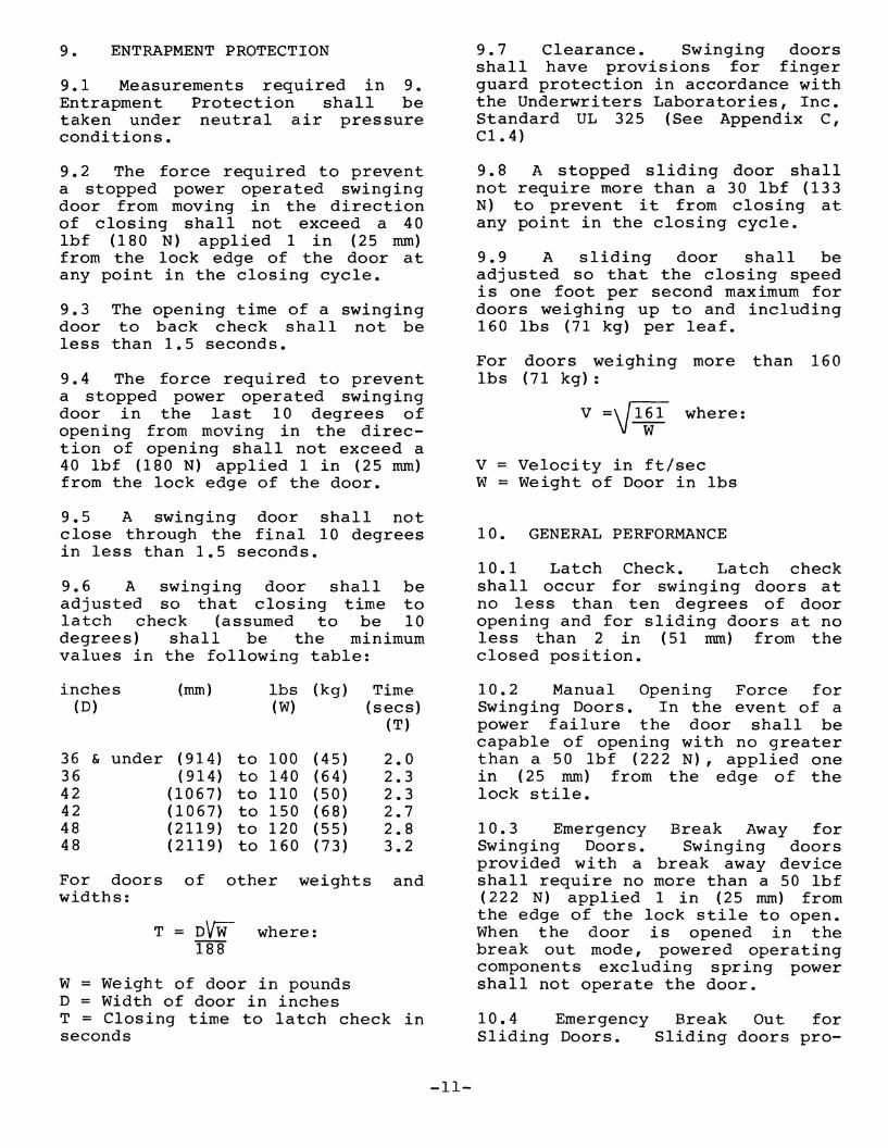
9. ENTRAPMENT PROTECTION
9.1 Measurements required in 9.Entrapment Protection shall betaken under neutral air pressureconditions.
9.2 The force required to preventa stopped power operated swingingdoor from moving in the directionof closing shall not exceed a 40lbf (180 N) applied 1 in (25 rom)from the lock edge of the door atany point in the closing cycle.
9.3 The opening time of a swingingdoor to back check shall not beless than 1.5 seconds.
9.4 The force required to preventa stopped power operated swingingdoor in the last 10 degrees ofopening from moving in the direction of opening shall not exceed a40 lbf (180 N) applied 1 in (25 rom)from the lock edge of the door.
9.5 A swinging door shall notclose through the final 10 degreesin less than 1.5 seconds.
9.6 A swinging door shall beadjusted so that closing time tolatch check (assumed to be 10degrees) shall be the minimumvalues in the following table:
9.7 Clearance. Swinging doorsshall have provisions for fingerguard protection in accordance withthe Underwriters Laboratories, Inc.Standard UL 325 (See Appendix C,C1.4)
9.8 A stopped sliding door shallnot require more than a 30 lbf (133N) to prevent it from closing atany point in the closing cycle.
9.9 A sliding door shall beadjusted so that the closing speedis one foot per second maximum fordoors weighing up to and including160 lbs (71 kg) per leaf.
For doors weighing more than 160lbs (71 kg):
V =\} 1:1 where:
v = Velocity in ft/secW = Weight of Door in lbs
10. GENERAL PERFORMANCE
10.1 Latch Check. Latch checkshall occur for swinging doors atno less than ten degrees of dooropening and for sliding doors at noless than 2 in (51 rom) from theclosed position.
W = Weight of door in poundsD = Width of door in inchesT = Closing time to latch check inseconds
36 & under ( 914) to 100 (45) 2.036 ( 914) to 140 (64) 2.342 (1067) to 110 (50 ) 2.342 (1067) to 150 (68 ) 2.748 (2119) to 120 (55 ) 2.848 (2119) to 160 (73) 3.2
For doors of other weights andwidths:
T = D\fTil where:188
inches(D)
(rom) lbs (kg)(W)
Time(sees)
(T)
-11-
10.2 Manual Opening Force forSwinging Doors. In the event of apower failure the door shall becapable of opening with no greaterthan a 50 lbf (222 N), applied onein (25 rom) from the edge of thelock stile.
10.3 Emergency Break Away forSwinging Doors. Swinging doorsprovided wi th a break away deviceshall require no more than a 50 lbf(222 N) applied 1 in (25 rom) fromthe edge of the lock stile to open.When the door is opened in thebreak out mode, powered operatingcomponents excluding spring powershall not operate the door.
10. 4 Emergency Break Out forSliding Doors. Sliding doors pro-

of thesamplehours
vided with a break away deviceshall require no more than a 50 lbf(222 N) applied at the lock stilefor the break out panel to open.Break away devices (swingingpanels) for doors that slide on theegress side of an opening shall beequipped with a self closing deviceor interrupt actuation of the operator when used in the break outmode. Break away devices incorporating swing out side Ii tes shallinterrupt actuation of the operatorwhen used in the break out mode.(See Appendix C, Cl.3)
10.5 Emergency Egress Test forSwinging and Sliding Doors.
10.5.1 Doors with poweroperators shall be installed in asimulated wall and door framingassembly of sufficient strength towithstand all forces required bythe tests. Installation shall bein accordance wi th manufacturer'sprinted instructions. Maintenanceand repair of other than break awayequipment is permitted to be performed during the testing cycles.
10.5.2 The test specimen shallbe of the largest door size to belisted by the manufacturer.
10.5.3 Cycle for 300,000 cyclesat a rate of 5 to 8 per minute.
10.5.4 Break away devices shallnot be lubricated or adjustedduring the test.
10.5.5 At every 50,000 cyclesduring the test, sliding andswinging doors shall undergo 6,000break out cycles wi thout failure.At the conclusion of the test,
,break out forces shall not exceedthose listed in 10.3 and 10.4.
11. SALT SPRAY TEST
11.1 A sample of the latching andhinge assembly of the break awaydevice of a power operated doorcontained in an approximately 25 in(635 rom) wide panel shall be
-12-
subjected to a sal t fog test inaccordance with ASTM B-117 for 168hours.
11.2 Record the release forceprior to conducting the test. Thisshall not exceed a 50 lbf (222 N).
11.3 At the conclusionexposure time, remove theand allow to dry for 24without cleaning.
11.4 Then cycle the sample 10times. The release force for thefirst cycle shall not exceed a 100lbf (445 N). Release forces forthe next 9 cycles shall not exceeda 50 lbf (222 N).
12. TESTING LABORATORY
12.1 Tests described in 10 and 11shall be performed under the supervision of a nationally recognizedindependent testing laboratory onpre-production samples prior toacceptance of the design for production and subsequent installation. Production units shall beunder an in-plant follow-up inspection service.

TABLE I-A MINIMUM EXPOSED MAT SIZES FOR SWINGING DOORS (see 3. 3.1 and3.3.2) (inches)
Door Opening Min. Width Safety Mat Min. Length Safety Mat Min. LengthSize Required 3 in Threshold 1 in Threshold
36 26 36 3/4 37 3/437 27 36 3/4 37 3/4 CENTER42 32 42 3/4 43 3/4 PIVOT43 33 42 3/4 43 3/4 SINGLES44 34 44 3/4 45 3/445 35 44 3/4 45 3/448 38 48 3/4 49 3/449 39 48 3/4 49 3/4
48 38 24 3/4 25 3/450 40 24 3/4 25 3/4 CENTER60 50 30 3/4 31 3/4 PIVOT62 52 30 3/4 31 3/4 PAIRS72 62 36 3/4 37 3/474 64 36 3/4 37 3/484 74 42 3/4 43 3/486 76 42 3/4 43 3/4
36 26 41 3/4 41 3/4 BUTT & OFFSET42 32 47 3/4 47 3/4 HUNG44 34 49 3/4 49 3/4 SINGLES48 38 53 3/4 53 3/4
48 38 29 3/4 29 3/4 BUTT & OFFSET60 50 35 3/4 35 3/4 HUNG72 62 41 3/4 41 3/4 PAIRS84 74 47 3/4 47 3/4
TABLE 2-A MINIMUM EXPOSED MAT SIZES FOR SLIDING DOORS (inches)
Clear Opening Minimum Exposed Minimum ExposedWidth Mat Length Mat Width
Required Required
Single 37 & under 43 See FiguresSlide Over 37 54 A-5 & A-6Bipart 61 & Under 43 andSlide Over 61 54 3.4.1 & 3.4.2
-13-

APPENDIX A (Not a part of ANSI/BHMA AI56.10)
CONTROL MAT LAYOUTS FOR SWINGING DOORS
Door Open ing
SINGLE DOOR ON BUTTSOR OFFSET PIVOTS
SINGLE DOOR ON2 3A" CENTER PIVOTS
~----Door Opening---------I~
PAIR OF DOORS ON BUTTSOR OFFSET PIVOTS
~----Door Opening-----~
PAIR OF DOORS ON2 3A" CENTER PIVOTS
-14-
Figure A-I(Ref. 3.3.1 & 3.3.2)
2 3A"
Figure A-2(Ref. 3.3.1 & 3.3.2)

APPENDIX A (Continued)
CONTROL MAT LAYOUTS FOR SWINGING DOORS
~---- Door Opening----~
SINGLE DOOR ON33,4" CENTER PIVOTS
PAIR OF DOORS ON3 3,4" CENTER PIVOTS
Figure A-3(Ref. 3.3.1 & 3.3.2)
CONTROL MAT LAYOUT FOR TWO-WAY TRAFFIC SWINGING DOOR
5" Min.
55" Min.
Door Opening
-15-
Guide Rail
Figure A-4(Re f. 3. 3 • 3 )

APPENDIX A (Continued)
CONTROL MAT LAYOUTS FOR SLIDING DOORS
Figure A-5(Ref. 3.4.1 & 3.4.2)
Minimum Req'd.
EJsed Length
==~;::;::- ~ 000 r
Activating
Clear Opening...---- Width-
II ~ Slide ~ JIIII
II /II /II .
/ PanicLL- Breakaway
SINGLE SLIDING DOOR
Opening Width
~--Min. Req'd. -~-.IExposed Width
II ~IIIIII /I I /.I I PanicLL- '/BreakaWay
BI-PARTING SLIDING DOOR
Minimum Req'd.
,."....,.....,......-:~~..,.....,.~E_xlsedLength
Door- - ~ Door
\
~ Slide ~ IIII
\I I Minimum Req'd.I I Exposed Length
" I IPanic ~ IIBreakaway ---u
Figure A-6(Ref. 3.4.1 & 3.4.2)
-16-
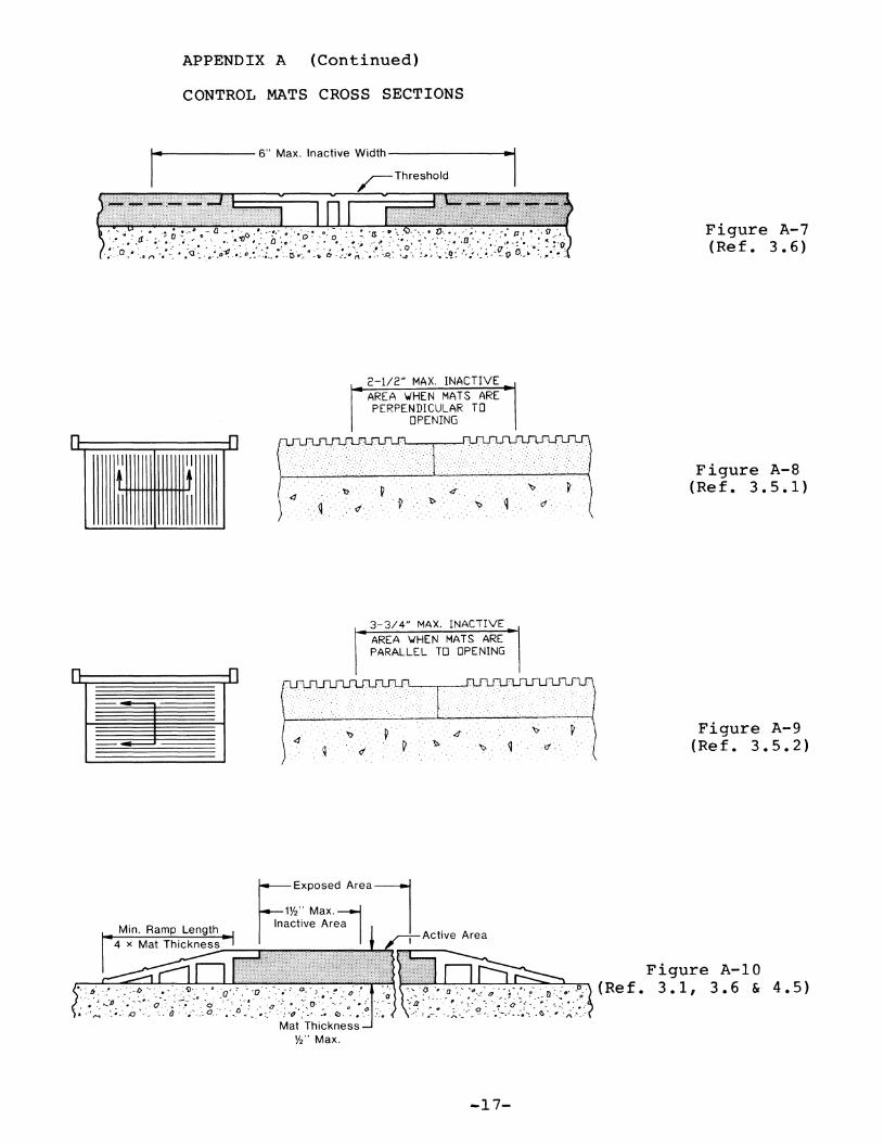
APPENDIX A (Continued)
CONTROL MATS CROSS SECTIONS
I~·~----- 6" Max. Inactive Width--------1--1
2-1/2 11 MAX. INACTIVEAREA ~HEN MATS AREPERPENDICULAR TO
OPENING
Figure A-7(Ref. 3. 6)
n 11II II
1+ tII II
". '.'4'......q ·.d. .' .~."'~"" .. ~.. " 'q d'·
3-3/4 11 MAX. INACTIVEAREA ~HEN MATS AREPARALLEL TO OPENING
.. \
Figure A-8( Re f. 3. 5 . 1 )
n n~
~
. :~ .
,,'...'. p'"·tt· . '..P.
.~
4'" .' .. '~... q...
~.' .
d·
Figure A-9(Re f. 3. 5 . 2 )
~Exposed Areal
1%" Max.Inactive Are~
,~ I I Active Area
::~b~ .:~;-_'~.i~~.~;(:~o; -(:.':; ..•~::.:.~-~ ,0. )::~~ -~:7:r.-:0··:·.:.~ .~< ~Mat Thickness
%" Max.
--17-
Figure A-lO(Re f. 3. 1 , 3. 6 & 4. 5 )

APPENDIX A (Continued)
GUIDE RAIL LAYOUTS FOR SWINGING DOORS
Figure A-II(Ref. 7.1 through 7.5)
Max.
:.: .
... :.
.
tApproach
.. : .....:.: ...:..:..•• :. .
...........:.. . :
Guide Rail
:.::,/ ...••...... ::•...•:..••...:...:... :•• :•.••:•.•:.. :.·.·:.·1.:. . :::: ..
.. ::: :
....: .
.
. . ..
1:···:·•..>< ......•........ . . ... . : ..I .: .•:: .:...•:::.::.:.:.::> ::. . :: .
...
I :.. . .: :
.... : .
I . :•...... :..: :..:::::: ::.:: ,II : .........•.......•rl·:···· .: ..•.• :•...••...•:....... .......•. ..••.
1
(' ...... ...: :.: :.
::::: ...
~de Rail
[
.
.. .
.. ......•
» ....
2
6" Max.----
Approach
+
}#
•...... ...
... . .... :. :.:.:
: :.: I
Guide Rail
Door Jamb Door Jamb
~---Width Of Door----t~~---Width Of Door---~
JAMB AND FLOOR MOUNTED FREE STANDING FLOOR MOUNTED
-18-

GUIDERAILS
DETECTIONAREA
DETECTION~----
AREA
MINIMUMACTUATINGDETECTION
. ~....,...-,.L-~I---- AREA
MINIMUMSA~ETY
DETECTION:.......,...:....,....:¥-~--AREA
MINIMUMDETECTION
:; .....~~-I-.,L----AREA
5"MIN.
~BS
5"MAX.
DETECTIONAR EA --------'
MINIMUMDETECTION
..~--,-.;-t-=-++--- AREA ---~~~
APPENDIX A (Continued)
GUIDERAIL
MINIMUM/ DETECTION
./' AREA1 _/
~ 5" MINIMUM5" TO DOORS EDGE
MIN.DETECTIONAREA
A 48" MINIMUM LENGTH
B DOOR OPENiNG \.IIDTH ISMEASURED FROM JAMB TO JAMB.
C = PATTERNS SHO\,./N ARE TYPICAL.
DETECTION PATTERN - SVINGING DOORSFIGURE A-12 (Ref. 5.1)
T\-IO \JAYTRAFFIC
SEE S2.3 FOR
ONE WAYTRAFFtC
A
JMINIMUMDETECTIONAREA ------+-----J-,:..~
DETECTION ---..-1AREA
DETECTIONAREA ..
11\"\ MINIMUM
~ DETECTIONMINIMUMDETECTION
AREA AREA A5"
A
C PATTERNS SHO'WN ARE TYPICAL.
B CLEAR DOOR OPENING VIDTH
A 54" MINIMUM LENGTH
DETECTION PATTERN - SLIDING DOORSFIGURE A-13 (Ref. 5.2)
-19-
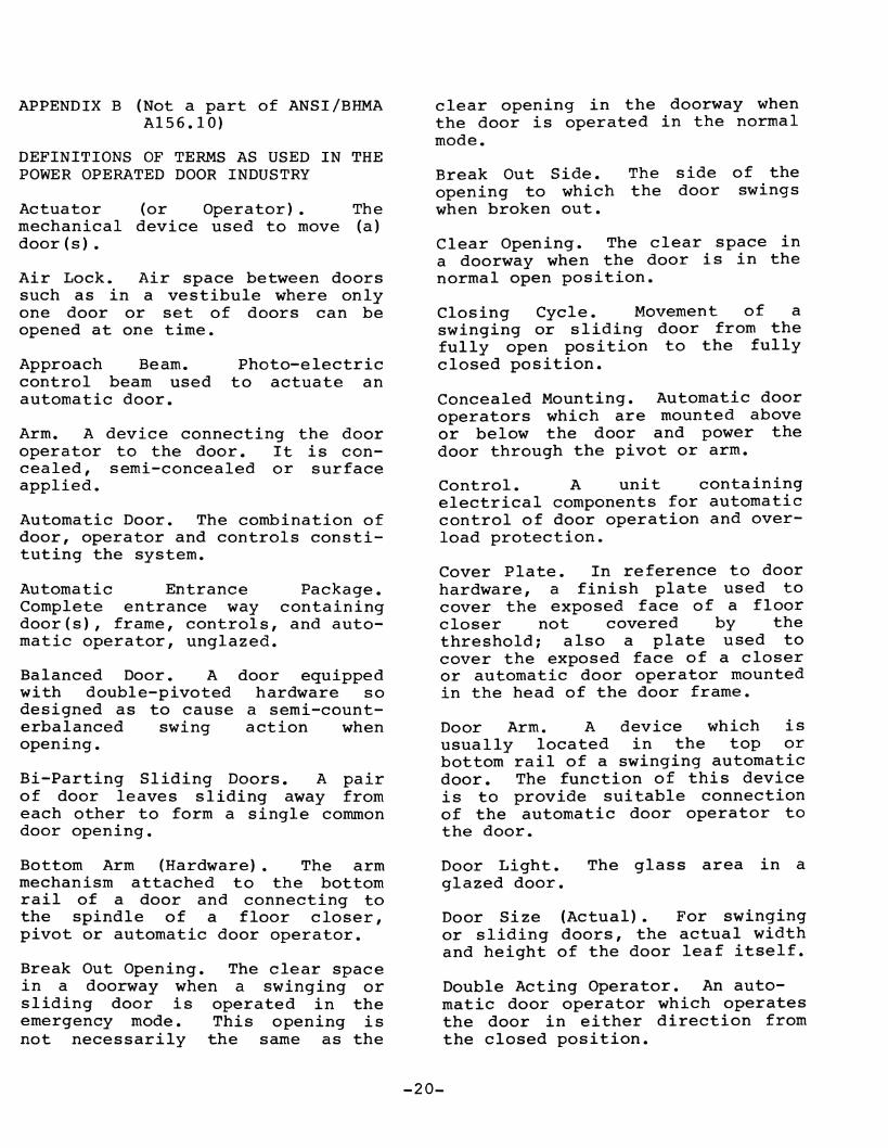
DEFINITIONS OF TERMS AS USED IN THEPOWER OPERATED DOOR INDUSTRY
APPENDIX B (Not a part of ANSI/BHMAA156.10)
Actuator (or Operator). Themechanical device used to move (a)door(s).
Automatic Door. The combination ofdoor, operator and controls constituting the system.
Door Arm. A device which isusually located in the top orbottom rail of a swinging automaticdoor. The function of this deviceis to provide suitable connectionof the automatic door operator tothe door.
Control. A unit containingelectrical components for automaticcontrol of door operation and overload protection.
Cover Plate. In reference to doorhardware, a finish plate used tocover the exposed face of a floorcloser not covered by thethreshold; also a plate used tocover the exposed face of a closeror automatic door operator mountedin the head of the door frame.
Concealed Mounting. Automatic dooroperators which are mounted aboveor below the door and power thedoor through the pivot or arm.
Closing Cycle. Movement of aswinging or sliding door from thefully open position to the fullyclosed position.
Clear Opening. The clear space ina doorway when the door is in thenormal open position.
Break Out Side. The side of theopening to which the door swingswhen broken out.
clear opening in the doorway whenthe door is operated in the normalmode.
Photo-electricto actuate an
Balanced Door. A door equippedwith double-pivoted hardware sodesigned as to cause a semi-counterbalanced swing action whenopening.
Automatic Entrance Package.Complete entrance way containingdoor(s), frame, controls, and automatic operator, unglazed.
Bi-Parting Sliding Doors. A pairof door leaves sliding away fromeach other to form a single commondoor opening.
Approach Beam.control beam usedautomatic door.
Arm. A device connecting the dooroperator to the door. It is concealed, semi-concealed or surfaceapplied.
Air Lock. Air space between doorssuch as in a vestibule where onlyone door or set of doors can beopened at one time.
Bottom Arm (Hardware). The armmechanism attached to the bottomrail of a door and connecting tothe spindle of a floor closer,pivot or automatic door operator.
Break Out Opening. The clear spacein a doorway when a swinging orsliding door is operated in theemergency mode. This opening isnot necessarily the same as the
Door Light. The glass area in aglazed door.
Door Size (Actual). For swingingor sliding doors, the actual widthand height of the door leaf itself.
Double Acting Operator. An automatic door operator which operatesthe door in either direction fromthe closed position.
-20-

Flush Glazing. A method of settingglass whereby glazing beads arerecessed and flushed with the edgeof the frame.
Guard Bar. A protective barapplied to the lower portion of adoor or sidelight to preventcollision with the glass.
Harness. A combination of wiresand connectors providing connectionof electrical controls to operatingequipment.
"In" Door. An automatic doorinstallation designed for trafficinto a building, space, etc.
Opening Cycle. Movement of aswinging or sliding door fromclosed position to fully open. Forswinging doors, this is normally 90degrees.
"Out" Door. An automatic doorinstallation designed for trafficout of a building or space.
Photo-Cell System. A deviceemploying the use of visible or invisible beams and receivers acrossan opening. When a beam is interrupted by a person or object, asignal is generated and used toactivate or de-activate the operation of an automatic door.
Knowing Act. With reference to theact of operating a door operator,such as pressing a switch with theknowledge of what will happen, andas opposed to "unknowing act".
In-Headeroperatorthe doorelectric,power.
Operator. A doorcompletely contained in
header requiring onlypneumatic or hydraulic
Photoelectric Control. A devicewhich employs the use of a visibleor invisible light beam across orthrough an opening. When the beamis interrupted by a person orobject, a signal is generated.
Power Closing. The closing of adoor by energy supplied fromhydraulics, pneumatics orelectricity.
Left Hand Traffic. The trafficrouting when the entrance door isplaced to the left of adjacent exitdoors.
Lintel. A horizontal structuralmember spanning an opening at itshead to carry construction abovethe opening.
Masonry Opening. The wall openinginto which the door is installed.
Meeting Stile. The vertical edgeof a door or window, in a pair,which is adjacent to the other dooror window. A parallel meetingstile is one which has a bevelededge paralleling the edge of thedoor. A round meeting stile is onehaving a rounded edge.
Power Open. The opening of a doorby energy supplied by other thanmanual means.
Power Uni t. A remote mechanicaldevice used to convert energy(usually electrical) to pneumatic,hydraulic, or mechanical energy fortransmission to the actuator.
Pressure Relief. A safety deviceto guard against excessive pressurebuildup. Usually with reference topneumatic or hydraulic systems.
Pull Cord Switch. A switch locatedabove the doorway having a cordwith handle extending down toapproximately 6 feet above thefloor. When the cord is pulled, aswitch is closed and a signal generated which can be used to actuatean automatic door operator.
-21-
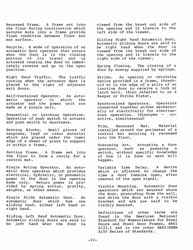
Recessed Frame. A frame set intothe floor during construction whichsecures mats into a frame provideflush condi tion between floor andmat surface.
Recycle. A mode of operation of anautomatic door operator that occurswhen the door is in the closingportion of its travel and isactuated causing the door to immediately reverse and go to the openposition.
Right Hand Traffic. The trafficrouting when the entrance door isplaced to the right of adjacentexit doors.
Self-Contained Operator. An automatic operator in which theactuator and the power unitaremade as a single unit.
Sequential or Latching Operation.Operation of push switch to actuateand push switch to deactuate.
Setting Blocks. Small pieces ofneoprene, lead or other materialwhich are placed under the loweredge of a sheet of glass to supportit within a frame.
Setting Frame. A frame set intothe floor to form a cavi ty for acontrol mat.
Single Acting Operator. An automatic door operator which provideselectrical, hydraulic, or pneumaticpower to the door in the openingmode only. Return power is provided by spring action, gravity,weights, or other means.
Single Slide Automatic Door. Anautomatic door which has onesliding leaf, ei ther left hand orright hand.
Sliding Left Hand Automatic Door.Automatic sliding doors are said tobe left hand when the door is
viewed from the break out side ofthe opening and it travels to theleft side of the viewer.
Sliding R.ight Hand Automatic Door.Automatic sliding doors are said tobe right hand when the door isviewed from the break out side ofthe opening and it travels to theright side of the viewer.
Spring Closing. The closing of adoor by energy supplied by springs.
Strike. An opening or retainingdevice provided in a frame, threshold or in the edge of a stile of aninactive door to receive a lock orlatch bolt. (Also referred to as aKeeper or Strike Plate).
Synchronized Operators. Operatorsconnected together either mechanically or electrically for simultaneous operation. (Synonyms coactive, simultaneous)
Trim, Recessed Mat. Materialinstalled around the perimeter of acontrol mat securing it recessedinto the floor.
Unknowing Act. Actuating a dooroperator, such as pressing aswitch, without specific knowledgeof how it is done or what willhappen.
variable Time Delay. A devicewhich is adjusted to change thetime a door remains open, afterremoval of the open signal.
Visible Mounting. Automatic dooroperators which are mounted abovethe door, protruding from the wall,and drive the door with a visiblebracket and arm are said to bevisibly mounted.
Definitions of other terms arefound in the American NationalStandard for Nomenclature for SteelDoors and Steel Door Frames, ANSIA123.1 and in the other ANSI/BHMAA156 Series of Standards.
-22-

SYMBOLS USED FOR POWER OPERATED SLIDING DOORS
TYPICAL DOOR ELEVATIONS
O-x-x-O X-O-O-x
---. .-.-
X-O-X O-X-x-x-X-O X-P P-x
Ern [J[]P-x-x-P
I 1I II - II II I
KEY
x - Sliding Panelo - Fixed SideliteP - Unit Without SideliteSO - Swing Out SideliteSX - Swing / Slide Panel
I~·---Width----------I----~ Type O-X ~~~-- ~
O-x The sliding panel shall be installedto the inside of the sidelite. Sliding panelslides along sidelite.
Type O-SX O-sx The swing-slide panel shall be installed to the exterior of the fixed sidelite.The swing-slide panels(s) (SX) shall swingout 90 degrees from any position of slidemovement.
Surface Mounted
~~~~ --~TypeP-SX~
For Letter Designation Units Are ViewedFrom Exterior, Left To Right.
SO-sx The swing out sidelite (SO) shall beinstalled to the exterior of the swing-slidepanel (SX). Swing out sidelite(s) is (are)provided to allow the sliding panel to swingout from any point of slide travel.
SO/SO-SX The swing out. sidelite (SO) shallbe installed to the exterior and interior ofthe swing-slide panel (SX). Swing outsidelite(s) exterior only is (are) providedto allow the sliding panel to swing out fromany point of slide travel.
O/SO-SX Swing pocket panel applied to theoutside of the unit.
P-SX Mounting of the unit is to the surfaceof the wall. As the door opens, the slidingpanel slides besides the wall.
-23-

APPENDIX C (Not a part of ANSI/BHMAAI56.10)
Cl REFERENCE TO OTHER STANDARDS
Cl.l When power operated firedoors are used, they are subject tothe requirements of the Standardfor Fire Doors and WindowsANSI/NFPA 80.*
Cl.2 Glazing in doors are subjectto criteria in the Standard,Performance Specifications andMethods of Test for Safety GlazingMa terial Used in Buildings, ANSIZ97.1* or CPSC requirements.
Cl.3 Where required by the authori ty having j ur isdiction, productsmeeting the requirements of thisStandard are also required tocomply wi th Chapter 5, Means ofEgress, of the Code for Safety fromFire in Buildings and Structures.ANSI/NFPA 101.*
Cl.4 Where required by the authority having jurisdiction, productsmeeting the requirements of thisStandard are required to complywith UL 325** and be listed orlabeled by a nationally recognizedindependent testing laboratoryand be under a periodic examinationservice.
Cl.5 Products meeting the requirements of this Standard shall alsocomply with applicable local building code requirements.
* Available from the AmericanNational Standards Institute, Inc.,11 West 42nd Street, New York, NewYork 10036.
APPENDIX D (not a part of ANSI/BHMAAI56.10)
D-l CONFORMANCE CRITERIA
Certification that products offeredmeet the requirements of thisStandard and conform to individualmanufacturer's drawings, specifications, standards and quality assurance practices are available and insome circumstances are required.Buyer requirements determine theneed for proof of conformance suchas first article inspection, testlaboratory reports, or listings.Specifiers requiring assertions ofconformance utilize statements ofconformance by individualmanufacturers, or test reportsacceptable to the buyer.
D-2 PRESERVATION, PACKAGING ANDPACKING
Unless other arrangements betweenbuyer and seller are made,preservation, packaging and packingshall be sufficient to protectcontainers and their contents undernormal shipping and handlingconditions from the source ofsupply to the destination point.
D-3 MARKING
Unless other arrangements betweenbuyer and seller are made, markingshall be in accordance with theindividual manufacturer's standardpractice.
**Available fromLaboratories, Inc.,Road, Northbrook, IL
Underwriters333 Pfingsten60662.
-24-

American National Standards
The standard in this booklet is one of over 11,000 standards approved todate by the American National Standards Institute, formerly the USAStandards Insti tute.
The Standards Institute provides the machinery for creating voluntarystandards. It serves to eliminate duplication of standards activities andto weld conflicting standards into single, nationally accepted standardsunder the designation, .. American National Standards".
Each standard represents general agreement among maker, seller and usergroups as to the best current practice with regard to some specific problem. Thus, the completed standards cut across the whole fabric of production, distribution, and consumption of goods and services. AmericanNational Standards, by reason of Institute procedures, reflect a nationalconsensus of manufacturers, consumers and scientific, technical and professional otganizations •
The Standards Institute, under whose auspices this work is being done, isthe United States clearing house and coordinating body for standardsactivity on the national level. It is a federation of trade associations,technical societies, professional groups and consumer organizations. Some1,000 companies are affiliated with the Institute as company members.
The American National Standards Institute is the United States member ofthe International Organization for Standardization (ISO) and the International Electro-technical Commission (lEe). Through these channels,American industry makes its position felt on the international level. American National Standards are on file in the libraries of the national standardsbodies of more than 50 countries.
American National Standards Institute11 West 42nd Street New York, NY 10036

ANSI/BHMA A156.1 0-1999
AMERICAN NATIONAL
STANDARD FOR
POWER OPERATED
PEDESTRIAN DOORS
"'-"'-"-~_w~_'"-_~_~'""'""-~" _ ~~ ~~ __ ~~»~~""_~"' ~
Hardware & Specialties08700
/",/
,,,,J./
.~J
American National Standard Institute11 West 42nd Street, New York, NY 10036

ANSIIBHMA AI56.10-1999Revision of:
ANSI AI56.10-1991
AMERICAN NATIONAL STANDARD
FOR
POWER OPERATED PEDESTRIAN DOORS
SPONSOR
BUILDERS HARDWARE MANUFACTURERS ASSOCIATION, INC.
APPROVED APRIL 26,1999AMERICAN NATIONAL STANDARDS INSTITUTE, INC.
AMERICAN NATIONAL STANDARD
An American National Standard implies a consensus of those substantially concerned with itsscope and provisions. An American National Standard is intended as a guide to aid themanufacturer, the consumer and the general public. The existence of an American NationalStandard does not in any respect preclude anyone, whether he has approved the standard or not,from manufacturing, marketing, purchasing, or using products, processes, or procedures notconforming to this standard. American National Standards are subject to periodic review and usersare cautioned to obtain the latest editions.
CAUTION NOTICE: This American National Standard is permitted to be revised or withdrawn atany time. The procedures of the American National Standards Institute require that action be takento reaffirm, revise, or withdraw this standard no later than five years from the date of publication.Purchasers of American National Standards receive current information on all standards by callingor writing the American National Standards Institute.
Published byBUILDERS HARDWARE MANUFACTURERS ASSOCIATION, INC.
355 Lexington Avenue New York, New York 10017
Copyright © 1999 by theBuilders Hardware Manufacturers Association, Inc.
Not to be reproduced without specific authorization from BHMA
Printed in the USA
10M /1200
This Standard was approved by ANSI under the Canvass Method. BHMA was accredited on 21March 1983 by ANSI as a sponsor using the Canvass Method.
2

FOREWORD (This Foreword is not a part ofANSI/BHMA A156.10)
The general classification of builders hardware includes a wide variety of itemswhich are divided into several categories. To recognize this diversity, a sectionalclassification system has been established. Power Operated Doors is one suchsection and this Standard is a result of the collective efforts of members of theBuilders Hardware Manufacturers Association, Inc. who manufacture this product.The total product standards effort is, therefore, a collection of sections, eachcovering a specific category of items.
Performance tests and, where necessary, dimensional requirements have beenestablished to insure a degree of safety. There are no restrictions on design exceptfor those dimensional requirements imposed for reasons of safety.
This Standard is not intended to obstruct but rather to encourage the development ofimproved products, methods and materials. The BHMA recognizes that errors willbe found, items will become obsolete, and new products, methods and materials willbe developed. With this in mind, the Association plans to update, correct and revisethese Standards on a regular basis. It shall also be the responsibility ofmanufacturers to request such appropriate revisions.
3

CONTENTS SECTION PAGE
1. General 5
2. Definitions 5 - 7
3. Swing Doors 7 - 8
4. Sliding Doors 8
5. Folding Doors 8
6. Guide Rails 8 - 9
7. Control Mats 9 - 12
8. Sensors 12 - 16
9. Knowing Act 16
10. Entrapment Protection 16 - 17
11. Signage 17 - 19
12. General Performance 19 - 20
Table 1 21
Table lA 22
Appendix A - Illustrations 23 - 38
Appendix B - Signage Illustrations .39 - 41
Appendix C -Definitions .42 - 44
Appendix D - Reference to Other Standards .44
Appendix E - Conformance, Packaging and Marking .44 - 45
4

1. GENERAL
1.1 Requirements in this Standard apply to power operated doors for pedestrian use, which openautomatically when approached by pedestrians and some small vehicular traffic or by a knowing act.Included are provisions to reduce the chance of user injury or entrapment. Power operated doors forindustrial or trained traffic are not covered in this Standard.
1.1.1 Where this Standard contains specifications relating to minimum or maximum dimensions ofvarious components of power operated doors for pedestrian use and some small vehicular traffic, suchdimensions are included to provide user protection for what are, in the industry, standard applicationconditions. This Standard does not apply to custom design installations.
1.2 This Standard does not apply to power assist and low energy power operated doors. Refer toANSI/BHMA A156.19 for Power Assist and Low Energy Power Operated Doors.
1.3 Required dimensions are expressed in US units first. The SI (metric) equivalents given mparentheses are approximate.
1.4 American National Standards referenced in A156.l0 are available from the American NationalStandards Institute, 11 West 42nd Street, New York, NY 10036. ASTM Standards referenced in A156.10are available from ASTM, 100 Barr Harbor Dr., West Conshohocken, PA 19428-2959 (also see AppendixC).
1.5 Tolerances. Where only minus tolerances are given, the dimensions are permitted to be exceeded atthe option of the manufacturers. All values that do not carry specific tolerances or are not marked maximumor minimum shall have the following tolerances: Linear dimensions shall be ± 1/16 inch (1.6 mm). Poundsor pound force shall be ± 2%. Degrees opening shall be ± 2 degrees. Electrical measurements shallbe±2%.
1.6 Tests described in this standard are performed under laboratory conditions. In actual usage, results varybecause of installation, maintenance and environmental conditions.
2. DEFINITION OF TERMS USED IN THIS STANDARD
2.1 Active Area. The area where a mat or sensor detects presence or motion.
2.2 Activating Zone. An area created by (a) sensor(s) such that the door will open when the area isentered by (a) person(s) or object(s).
2.3 Actuator (or Operator). The mechanical device used to move (a) door(s).
2.4 Automatic Door Operator. A power operated mechanism that is attached to a door for the purpose ofmechanically opening and closing a door upon the receipt of an actuating signal.
2.5 Back Check. The checking or slowing down of the speed of door opening before being fully opened.
2.6 Balanced Door. A door equipped with a hinge that moves the hinge pivot point from the hinge stile ofthe door towards the centerline of the door a small distance. A balanced door is employed when a reducedopening force is required.
5
2.7 Break Away Device. A safety device other than an exit device that permits egress under emergencyconditions. Also called an Emergency Release.
2.8 Break Out The process of activating a break away device causing the door or panel to swing in thedirection of egress.
2.9 Break Out Opening. The clear space in a doorway when a swinging or sliding door is operated inthe emergency mode. This opening is not necessarily the same as the clear opening in the doorway when thedoor is operated in the normal mode.
2.10 Break Out Side. The side of the opening to which the door swings when broken out.
2.11 Center Pivoted. A door that has the pivot point of the hinge located on the centerline of the doorthickness.
2.12 Clear Opening for Automatic Doors.
• Swing Doors - With the door open 90 degrees, the clear width is measured between the face of thedoor and jamb or jamb stop.
• Pair of Swing Doors - With the doors open 90 degrees the clear width is measured between the faceof the two open doors.
• Sliding or Folding Doors - In the fully opened position, the clear opening is measured from theedge of the leading stile to the jamb or jamb stop if present.
• Pair of Sliding or Folding Doors - In the fully opened position, the clear opening is measuredbetween the edges of the leading stiles of the two doors.
2.13 Closing Cycle. Movement of a swinging or sliding door from the fully open position to the fullyclosed position.
2.14 Closing Time. Time from starting of a door closing until it is at rest fully closed.
2.15 Control A unit containing electrical components for automatic control of door operation and overloadprotection.
2.16 Control Mat An activating or safety device placed on the floor on either side of a doorway sensingthe presence of a person or object. It is constructed of a rubber like material with slip resistant surface and iseither recessed into or surface mounted on the floor.
2.17 Control Mat, Activating. A control mat which when activated causes a door to open.
2.18 Control Mat, Safety. A control mat which when activated prevents a door from opening or holds adoor open.
2.19 Cycle. The action of an automatic door operator starting with activation through opening and fullclosing of (a) door(s).
2.20 Door Opening for Automatic Doors.
• Swing or Folding Doors (Singles or Pairs) The smallest width dimension of a door opening,measured jamb to jamb.
• Sliding Doors - In the fully opened position, the door opening is measured from the edge of theleading stile to the jamb or stop if present.
6

• Pair of Sliding Doors - In the fully opened position, the door opening is measured between theedges of the leading stiles of the two doors.
2.21 Exposed Area. The visible area of a control mat after the trim is installed.
2.22 Finger Guard A device applied at the hinge stile of a door or to the hinge jamb adjacent to the doorpreventing damage to hands or fingers.
2.22 Folding Door. A pivoted swing panel hinged to a passive panel, the other end of which is captured ina guide, thus allowing it to slide as both panels swing into a V shape (the fold).
2.24 Guide Rail A separator used with power operated doors for traffic separation and control.
2.25 Knowing Act With reference to the act of operating a door operator, such as pressing a switch with theknowledge ofwhat will happen.
2.26 Latch Check. The checking or slowing down of the speed of closing of a door before being fullyclosed.
2.27 Offset Hung. A door which has a hinge pivot point located off the centerline of the door thickness.
2.28 Motion Sensor. A sensor designed to detect the movement of a person or equivalent in the vicinity ofthe doorway and give a control signal to the power operated door.
2.29 Power Operated Door (Automatic Door). The combination of door, operator and controlsconstituting the system. Also called an Automatic Door.
2.30 Presence Sensor. A sensor designed to detect the presence of a person or equivalent in the vicinity ofthe doorway and give a control signal to the power operated door.
2.31 Safety Zone. An area protected such that when a swinging or folding door is fully open or closed or asliding door is fully open, the door operator shall not operate when the area is occupied by a person or itsequivalent.
2.32 Sensor. A device that detects the motion or presence of a person or object.
2.33 Threshold. A floor mounted horizontal member installed beneath a closed door or in a clear dooropemng.
2.34 Trained Traffic. People trained III the safe use and operation of a particular automatic doorinstallation.
2.35 Trim, Mat. Material installed around the perimeter of a control mat securing it to the floor.
3. SWINGING DOORS
Automatic swing door systems have a variety of configurations, including:
• a single door swinging in or out, left-handed or right-handed• a pair of doors simultaneously swinging in the same direction.
7
The door operator is concealed or surface applied. The doors are center pivoted, offset hung, balanced orhinged. No matter what the configuration or system, automatic swinging doors shall include guide rails,sensors, or control mats and signage for the safety and convenience of the user according to the following:
• Guide Rails• Control Mats• Sensor
see section 6.1see section 7.1 & 7.3see section 8.1
• Knowing Act• Entrapment• Signage
see section 9.see section 10see section 11.1, 11.2
4. SLIDING DOORS
Automatic sliding doors are flat panels that slide horizontally and linearly. These systems have such avariety of configurations that symbols have been assigned to the individual panels that make up an entryway.See Table 1 for definitions of0, SO, X, SX and P panels.
No matter what the configuration or system, automatic sliding doors shall include sensors, or control matsand signage for the safety and convenience of the user according to the following:
• Control Mats• Sensor• Knowing Act
see section 7.1, & 7.4see section 8.2see section 9
• Entrapment• Signage
see section 10see section 11.1, & 11.3
5. FOLDING DOORS
Automatic folding doors are comprised of two or more separate panels, of which one panel swings, and theother panel slides in a guide. Because of the number ofleaves involved, see Figure A-14 for definitions ofFX and FS panels.
Automatic folding doors include a variety of configurations, including:
• a single folding door folding in or out, left hand or right hand.• a pair of doors simultaneously folding in or out, left hand and right hand.
No matter what the configuration or system, automatic folding doors shall include guide rails, sensors, orcontrol mats and signage for the safety and convenience of the user according to the following:
• Guide Rails• Control Mats• Sensor
see section 6.2see section 7.1, & 7.5see section 8.3
• Knowing Act• Entrapment• Signage
see sections 9see section 10see section 11.1 & 11.4
6. GUIDE RAILS
6.1 Guide Rails for Swing Doors (See Figures A-2, A-4 & A-ll)
6.1.1 Two guide rails shall be installed on the swing side of each door. Rails shall project at least to theleading edge of the widest door in the fully open position.
Exception #1: A wall or separator is permitted to be used in place of a rail, provided that it meets the criteriain 6.1.2 through 6.1.5.
8

Exception #2: Guide rails for swinging doors serving both egress and ingress shall project out from the faceof the door jambs on the swing side to no less than the outside leading edge of the open door plus 55 inches(1400 mm) (See Figure A-2 & A-4).
6.1.2 A guide rail shall be 30 inches (760 mm) high minimum measured from the floor surface.
6.1.3 A guide rail shall have a panel or a divider to inhibit access to the protected area.
6.1.4 There shall be 6 inches (150 mm) maximum clearance between the rail and the door in the fullyopen position or between the rail and the leading edge of the door at the point in its arc of travel when it isclosest to the rail. There shall be a 2 inch (51 mm) minimum clearance between the rail at the hinge side andthe door in the fully open position.
6.1.5 Free standing guide rails shall have a maximum dimension between the rail and jamb (or otheradjacent surface) of2 inches (51 mm).
6.2 Guide Rails for Folding Doors (See Figures A-14 & A-IS)
6.2.1 A guide rail shall be installed for each FS panel on the folding side of each door and shall projectbeyond the fold open position not less than:
12 inches (305 mm) minimum, for two way traffic or one way traffic approaching the fold side or5 inches (125 mm) minimum, for one way traffic approaching the non-fold side.
Exception: A wall separator is permitted to be used in place of a rail, provided that it meets the criteria in6.2.2 through 6.2.5.
6.2.2 A guide rail shall be 30 inches (760 mm) minimum measured from the finished floor surface.
6.2.3 A guide rail shall have a panel or divider to inhibit access to the protected area.
6.2.4 There shall be 6 inches (150 mm) maximum clearance between the rail and the door in the fullyopen position or between the rail and the leading edge of the door at the point in its arc of travel when it isclosest to the rail. There shall be a minimum clearance of 2 inches (51 mm) between the rail at the hinge sideand the door in the fully open position.
6.2.5 Free standing guide rails shall have a maximum clearance between the rail and jamb (or otheradjacent surface) of2 inches (51 mm).
7. CONTROL MATS-REQUIREMENTS (SEE TABLES I-A)
7.1 The edge of the exposed area of all control mats shall not exceed 1/2 inch (12.7 mm) thickness (SeeFigure A-10).
7.2 Not used.
9
7.3 Swinging Doors
7.3.1 The width of the exposed area of an activating or safety control mat shall be the width of the dooropening less a maximum of 5 inches (125 mm) measuring from both sides for a total maximum of 10 inches(255 mm) (See Figures A-I, A-2, A-3 & A-4).
7.3.2 A safety zone shall be provided on the swing side of the door. If a safety control mat is used, thelength of the exposed area shall extend a minimum of 5 inches (125 mm) beyond the lead edge of the door inthe open position (See Figures A-I, A-2, A-3 & A-4).
7.3.3 Swinging doors serving both egress and ingress shall have a series of control mats on the swing sideof the door(s) consisting of a safety control mat nearest the opening with a length of exposed area a minimumof 5 inches (125 mm) beyond the lead edge of the door in the open position and one or more activatingcontrol mats totaling an additional 55 inches (1400 mm) of exposed length (See Figure A-2 & A-4).
7.3.4 The exposed length of the activating mat on the non swing side shall be a minimum of 43 inches(1090 mm).
7.4 Sliding Doors
7.4.1 The width of the exposed area of an activating mat shall be the clear opening width less a maximumof 5 inches (125 mm) measured from both sides for a total maximum of 10 inches (255 mm) (See Figures A5 & A-6).
7.4.2 Sliding doors shall have an activating control mat with a minimum exposed length of 43 inches(1090 mm) (See Figures A-5 & A-6).
7.4.3 Sliding doors used for one way traffic shall be provided with a control mat that will hold the dooropen or return the door to the open position when approached by a person from the side not intended for use.The activating length shall extend a minimum of 24 inches (610 mm) from the face of the door and be
effective to comply with 7.6.3. The width of the control mat shall comply with 7.4.1. The control mat shallbe deactivated when the door(s) is (are) within 6 inches (150 mm) of the fully closed position.
7.5 Folding Doors
7.5.1 The width of the exposed area of an activating or safety control mat shall be the width of the dooropening less a maximum of 5 inches (127 mm) measuring from both sides for a total maximum of 10 inches(255 mm) (See Figure A-16).
7.5.2 A safety zone shall be provided on the fold side of the door. If a safety mat is used, the length ofthe exposed area shall extend a minimum of 5 inches (125 mm) beyond the edge of the door in the openposition (See Figure A-16).
7.5.3 Folding doors serving both egress and ingress shall have a series of control mats on the fold side ofthe door(s) consisting of a safety control mat nearest the opening with a minimum of 5 inches (125 mm)beyond the edge of the door in the open position and one or more activating control mats totaling anadditional 48 inches (1220 mm) of exposed length (See Figure A-16).
10

7.5.4 The exposed length of the activating mat on the non fold side shall be a minimum of 43 inches(1090 mm).
7.6 Joining of Control Mats
7.6.1 Control mats are permitted to be fitted side by side with the longest dimension perpendicular to theopening and shall not have an inactive area at the meeting line exceeding 2 1/2 inches (63 mm) (See FigureA-8).
7.6.2 Control mats are permitted to be fitted side by side with the longest dimension parallel to the dooropening and shall not have an inactive area at the meeting line exceeding 3 3/4 inches (95 mm) (See Figure A9).
7.6.3 Control mats meeting at a threshold shall not have an inactive width exceeding 6 inches (150 mm)including threshold width (See Figure A-7).
7.6.4 The active area ofa control mat shall be a maximum of 1 1/2 inches (38 mm) from any edge of theexposed area (See Figure A-10).
7.7 Performance Requirements of Control Mats
7.7.1 A control mat circuit shall operate at 30 volts rms or less.
7.7.2 Control Mat Sensitivity Test
7.7.2.1 Circuit shall be activated when a solid steel test disc 2.26 inches (57 mm) in diameter isdepressed with a 25 lbf (110 N) applied vertically, perpendicular to the disc in accordance with 7.7.2.3 and7.7.2.4, except that if the circuit is not activated, a 30 Ibf(130 N) shall be applied at the area of the electricalcontact connections and adjacent locations described in 7.7.2.3. Activation is achieved when the 'off statecircuit resistance and capacitance, which must be greater than 5000 ohms and less than 100 nanofarads,changes to an 'on' state circuit resistance of less than 400 ohms.
7.7.2.2 The Control Mat shall be divided into 12 equal rectangles covering the active area, exceptwhen the length of the mat is such that the length of each rectangle would be greater than 12 inches (305mm) then the mat shall be divided into 15 or 18 equal rectangles so that the length of each rectangle is notless than 8 inches (205 mm) or more than 12 inches (305 mm).
7.7.2.3 The test disc shall be placed in the approximate center of each interior rectangle. Forperimeter rectangles, place the disc so that it abuts the edge of the active area 1 1/2 inches (38 mm) from theexposed edge of the mat at the approximate center line of the rectangle. Compensating for the weight of thedisc, apply a force to activate the circuit and take a single reading. If the disc and force fail to activate theControl Mat at any of the test locations, place the disc on adjacent 90 degree tangents to the test location(s)within the active area of the mat. The disc shall activate the mat at all adjacent locations. If a check on theinitial reading is desired, a period of at least 10 minutes shall be allowed between readings. One test discdiameter shall be omitted from each comer of the mat when testing. The mats shall be tested on a flat, rigidsurface.
7.7.2.4 The test shall be conducted at 68 degrees ±5 degrees F (20 degrees ±2 degrees C).
11

7.7.3 Control Mat Friction Test
7.7.3.1 A control mat shall have a coefficient of friction when dry and clean of not less than 0.66when tested in accordance with 7.7.3.2 through 7.7.3.6.
7.7.3.2 Coefficient of friction (M) shall be measured using a standard friction block (N) having adiameter of 4 inches (100 mm), weighing 15 lbs. (7 kg) and equipped with a Neolite bottom 1/4 inch (6 mm)thick. The Neolite composition rubber shall have a smooth flat bottom surface without ridges and Shore Ahardness of 90 ± 3. The sheen shall be removed from the Neolite surface prior to use. To prepare theassembly surface prior to its initial use, place a sheet of 400 grit wet or dry silicon carbide paper on a flatsurface. Sand the Neolite material gently by moving the assembly back and forth four times for a distance ofabout 4 inches (100 mm). Repeat at an angle of 90 degrees. This constitutes one cycle of surfacepreparation. This procedure is to be repeated for a total of 10 cycles. Neolite is available from Biltrite Corp.,P.O. Box 9045, Waltham, MA 02254.
7.7.3.3 The block shall be placed in the middle of the mat with a linear scale calibrated in pounds(kilograms) attached.
7.7.3.4 Force required to just begin to move the block in any direction shall be a minimum of a 10Ibf(44 N) applied 1/2 inch (13 mm) from the bottom of the block.
7.7.3.5 The test shall be conducted in a room temperature of 68 degrees F ± 5 (20 degrees C ± 2).Mats shall be placed in the test room not less than 4 hours prior to the test.
7.7.3.6 The formula used for determining the coefficient of friction (M) shall be M = F + N whereN = 15 lbs. (7 kg) weight (See 7.7.3.2) and F = 10 Ibf(44 N) minimum (See 7.7.3.4).
7.7.4 Control Mat Trim. Surface applied control mats shall be secured to the floor with trim having atapered lead up to a minimum of 4 times the mat thickness at the exposed edge (See Figure A-I 0).
8. SENSORS
Motion sensors shall detect a 28 inch (710 mm) minimum high person or equivalent and moving at a rate of6 inches (150 mm) per second minimum toward the center of the door within the detection areas described.
Presence sensors shall detect a stationary 28 inch (710 mm) minimum high person or equivalent within thedetection areas described.
8.1 Swinging Doors
8.1.1 Non-swing side activating detection areas shall have a minimum width equal to the width of thedoor opening less 5 inches (125 mm) maximum from both sides for a total of 10 inches (255 mm) maximummeasured at 15 inches (380 mm) and 30 inches (760 mm) perpendicular from the face of the closed door.The length from the face of the door shall be 43 inches (1090 mm) minimum measured at the center of thedoor opening. Detection shall be effective to within 5 inches (125 mm) from the face ofthe door measured atthe center ofthe door opening (See Figure A-12A).
8.1.2 A safety zone shall be provided on the swing side of all power operated swinging doors.
12
8.1.2.1 If an overhead sensor(s) is used to provide a safety zone, the length of the active area shall beeffective to within 5 inches (125 mm) of the face of the closed door measured at the center of the dooropening. The safety zone shall extend 5 inches (125 mm) minimum beyond the leading edge of the door inthe open position when measured at the center of the door opening. The width of the active area measuredperpendicular from the face of the closed door shall be the door opening less 5 inches (125 mm) maximummeasuring both sides for a total of 10 inches (255 mm) maximum measured parallel to the face of the door ata distance of 15 inches (380 mm) and 30 inches (760 mm) (See Figure A-12A).
8.1.2.2 If a door mounted sensor is used to provide a safety zone, it shall provide an active area 5inches (125 mm) maximum from the face of the door for the width of the door less 5 inches (125 mm) fromthe pivot point. A door mounted sensor on either side of the door shall detect a 28 inch minimum (710 mm)high person or equivalent in the swing path, during the opening or closing cycle and shall cause the door toreverse direction, stop or slow down to a maximum latch edge speed of 4 inches per second (100 mm persecond) measured within 1 inch (25 mm) of the latch edge before any contact is made (See Figure 12B).
8.1.3 Swinging doors serving both egress and ingress shall have a safety zone on the swing side, asdefined in 8.1.2 and an activating zone extending an additional 55 inches (1400 mm) from the leading edgeof the door in the open position (See Figure A-12A).
8.1.4 If a sensor is used for activation and a safety control mat is used as a safety zone, the exposed areaof the safety control mat shall extend 5 inches (125 mm) minimum beyond the edge of the door in the openposition and:
1) extend 5 inches (125 mm) into the non-swing side area of the door measured from the face of the door;or
2) the door opening area shall be provided with a presence sensor that shall be used to prevent a fully opendoor(s) from closing when a person is in the space between two non overlapping activation or safetydetection areas; or
3) the door closing cycle shall have a delay of 4 seconds minimum after the activating area is clear; or
4) be equipped with a door mounted sensor on the non swing side as described in 8.1.2.2.
8.1.4.1 The width ofa safety control mat shall be in accordance with 7.3.1 (See Figure A-12A).
8.1.5 Ifthe distance between the two non overlapping zones exceeds 8 inches (205 mm) when sensors areused to provide both an activation and a safety zones, the door system shall:
1) be equipped with a safety control mat; or
2) be equipped with a presence sensor across the door opening; or
3) have a door closing cycle delay of4 seconds minimum after the activation area is clear; or
4) be equipped with a door mounted sensor on the non swing side as described in 8.1.2.2.
13

8.2 Sliding Doors
8.2.1 Activating detection areas shall have a minimum width equal to the width of the clear openingmeasured at 15 inches (380 mm) and 30 inches (760 mm) perpendicular from the face of the closed door(s).The length from the face of the door shall be 43 inches minimum (1090 mm) measured at the center of theclear opening. Detection shall be effective to within 5 inches (125 mm) from the face of the door measuredat the center of the clear opening (See Figures A-13 & 18A, B & C).
8.2.2 A presence sensor shall be used to prevent a fully open door(s) from closing when a person is in thespace between two non overlapping activation detection areas (See Figure 18A, B & C).
8.2.2.1 Ifphoto electric beams are used (See Figure A-18A.):
(1) A minimum of two photo electric beams shall be installed with the lower beams installed 6 28" (150 - 710 mm) and top beam 45" - 55" (1145 - 1400 mm) from the floor; and
(2) They shall be installed within 3 inches (76 mm) from the center of the slide door if both areinstalled on same side or within 5 inches (125 mm) of the centerline of the slide door if morethan two photo electric beams are installed on each side of the sliding door; and
(3) The beams shall remain active from fully open to within 6 inches (150 mm) of closed.
8.2.2.2 If an area presence sensor is used through the door opening it (See Figure A-18B):
(1) Shall detect a 28 inch (710 mm) minimum high person or equivalent and extend out aminimum of 5 inches (125 mm) from the face ofthe door on each side; and
(2) The detection zone shall remain active from open to within 6 inches (150 mm) of close orshall have a photo electric beam at 6" - 28" (150 - 710 mm) from the floor or a time delay of 4seconds minimum after the activation signal ceases (See Figure 18B).
8.2.2.3 Ifpresence sensors are installed on each side of the sliding door opening (See Figure A-18C):
(1) They shall not have an inactive area more than 5 inches (125 mm) extending out from the faceof the door. If the inactive area exceeds 3 inches (76 mm) from the face of the door, one beam isrequired at 6" - 28" (150 - 710 mm) from the floor; and
(2) The detection zone shall remain active from open to within 6 inches (150 mm) of closed orshall have a photo electric beam at 6" - 28" (150 - 710 mm) from the floor or a time delay of 4seconds minimum after the activation signal ceases.
8.2.3 Sliding doors used for one way traffic shall be provided with a sensor that holds the door open orreturns the door to the open position when approached by a person from the side not intended for use. Theactivating zones shall extend a minimum of24 inches (610 mm) from the face ofthe door and be effective towithin 5 inches (125 mm) from the face of the door both measured at the center of the door opening. Thewidth of the activating zone shall be effective to within 5 inches (125 mm) of each side of the clear dooropening. The sensor shall be deactivated when the door(s) is (are) within 6 inches (150 mm) of the fullyclosed position. The sensor shall detect an object defined in 8.0.
14
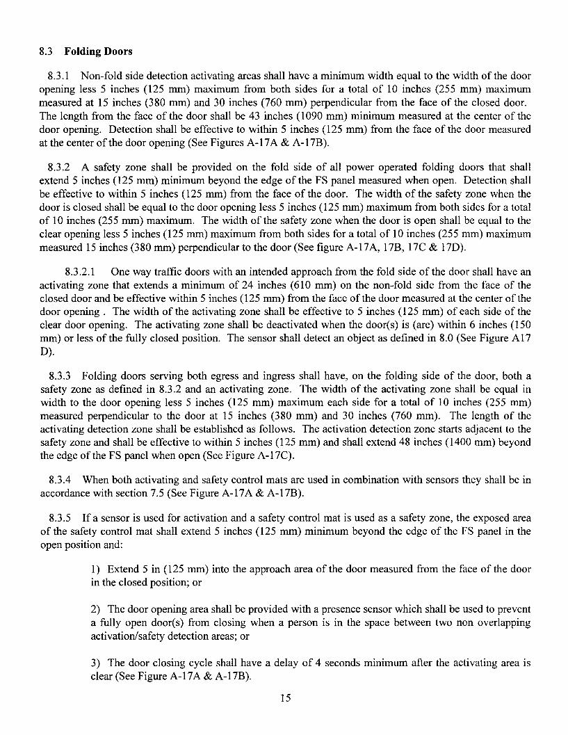
8.3 Folding Doors
8.3.1 Non-fold side detection activating areas shall have a minimum width equal to the width of the dooropening less 5 inches (125 mm) maximum from both sides for a total of 10 inches (255 mm) maximummeasured at 15 inches (380 mm) and 30 inches (760 mm) perpendicular from the face of the closed door.The length from the face of the door shall be 43 inches (1090 mm) minimum measured at the center of thedoor opening. Detection shall be effective to within 5 inches (125 mm) from the face of the door measuredat the center of the door opening (See Figures A-17A & A-17B).
8.3.2 A safety zone shall be provided on the fold side of all power operated folding doors that shallextend 5 inches (125 mm) minimum beyond the edge of the FS panel measured when open. Detection shallbe effective to within 5 inches (125 mm) from the face of the door. The width of the safety zone when thedoor is closed shall be equal to the door opening less 5 inches (125 mm) maximum from both sides for a totalof 10 inches (255 mm) maximum. The width of the safety zone when the door is open shall be equal to theclear opening less 5 inches (125 mm) maximum from both sides for a total of 10 inches (255 mm) maximummeasured 15 inches (380 mm) perpendicular to the door (See figure A-17A, 17B, 17C & 17D).
8.3.2.1 One way traffic doors with an intended approach from the fold side of the door shall have anactivating zone that extends a minimum of 24 inches (610 mm) on the non-fold side from the face of theclosed door and be effective within 5 inches (125 mm) from the face of the door measured at the center of thedoor opening. The width of the activating zone shall be effective to 5 inches (125 mm) of each side of theclear door opening. The activating zone shall be deactivated when the door(s) is (are) within 6 inches (150mm) or less of the fully closed position. The sensor shall detect an object as defined in 8.0 (See Figure A17D).
8.3.3 Folding doors serving both egress and ingress shall have, on the folding side of the door, both asafety zone as defined in 8.3.2 and an activating zone. The width of the activating zone shall be equal inwidth to the door opening less 5 inches (125 mm) maximum each side for a total of 10 inches (255 mm)measured perpendicular to the door at 15 inches (380 mm) and 30 inches (760 mm). The length of theactivating detection zone shall be established as follows. The activation detection zone starts adjacent to thesafety zone and shall be effective to within 5 inches (125 mm) and shall extend 48 inches (1400 mm) beyondthe edge of the FS panel when open (See Figure A-17C).
8.3.4 When both activating and safety control mats are used in combination with sensors they shall be inaccordance with section 7.5 (See Figure A-17A & A-17B).
8.3.5 If a sensor is used for activation and a safety control mat is used as a safety zone, the exposed areaof the safety control mat shall extend 5 inches (125 mm) minimum beyond the edge of the FS panel in theopen position and:
1) Extend 5 in (125 mm) into the approach area of the door measured from the face of the doorin the closed position; or
2) The door opening area shall be provided with a presence sensor which shall be used to preventa fully open door(s) from closing when a person is in the space between two non overlappingactivation/safety detection areas; or
3) The door closing cycle shall have a delay of 4 seconds minimum after the activating area isclear (See Figure A-17A & A-17B).
15

8.3.6 If the distance between the two non-overlapping zones exceeds 8 inches (205 mm) when sensors areused to provide both an activation and safety zones, the door system shall:
1) Be equipped with a safety control mat; or
2) The door opening shall be equipped with a presence sensor across the door opening; or
3) Have a door closing cycle delay of 4 seconds minimum after the activation area is clear (SeeFigure A-17A & A-17B).
9. KNOWING ACT DOOR ACTUATION
9.1 Use of an activating device which requires a knowing act to activate the automatic door shall meet thefollowing requirements:
9.1.1 Be installed in a location within view of the automatic door; and
9.1.2 Have an installation height of a minimum of 36 inches (915 mm) and a maximum of 48 inches(1220 mm); and
9.1.3 Be located a maximum distance of 12 feet (3.7 m) from the center ofthe door; and
9.1.4 The door shall remain open for a minimum of 5 seconds after release of the activating device; and
9.1.5 The door shall be equipped with a safety zone(s) as required in this standard for the type door anddetection system selected.
9.1.5.1 The door shall be equipped with a secondary activating zone of size and function as definedin 7.4.3 or 8.2.3.
10. ENTRAPMENT PROTECTION
10.1 Entrapment Protection measurements shall be taken under neutral air pressure conditions.
10.2 The force required to prevent a stopped power operated swinging door from moving in the directionof closing shall not exceed a 40 lbf (180 N) applied 1 inch (25 mm) from the lock edge of the door at anypoint in the closing cycle.
10.3 The opening time of a swinging or folding door to back check shall not be less than 1.5 seconds.
10.4 The force required to prevent a stopped power operated swinging door in the last 10 degrees ofopening from moving in the direction of opening shall not exceed 40 lbf (180 N) applied 1 inch (25 mm)from the lock edge of the door.
10.4.1 For folding doors, the force required to prevent a stopped door, in the last 10 degrees of theopening, from moving in the direction of opening shall not exceed 40 lbf (180 N) applied 1 inch (25 mm)from the leading edge of the FS leaf.
16

10.5 A door shall not close through the final 10 degrees for swinging doors or no less than 2 inches (51mm) for folding doors in less than 1.5 seconds.
10.6 Swing, sliding and folding doors utilizing sensors or control mats shall remain open a minimum of1.5 seconds after loss of detection.
10.7 A swinging door shall be adjusted so that closing time to latch check shall be the minimum values inthe following table:
Inches (mm) (D) 36 (914) & 36 (914) 42 (1067) 42 (1067) 48 (2119) 48 (2119)under
Lbs. (kg) (W) to 100 (45) to 140 (64) to 110 (50) to 150 (68) to 120 (55) to 160 (73)Time T (sees.) 2.0 2.3 2.3 2.7 2.8 3.2
For doors of other weights and widths:
T = D-IW /188 where:W = Weight of door in poundsD = Width of door in inchesT = Closing time to latch check in seconds
10.8 Clearance. Center pivoted swinging & folding doors shall have provIsIOns for finger guardprotection if the door clearance at the hinge side is greater than 1/4 inch (6.4 mm) and less than 3/4 inch (19mm) with the door in any position.
10.9 A stopped sliding or folding door shall not require more than 30 lbf (133 N), measured at the leadingedge, to prevent it from closing at any point in the closing cycle.
10.10 A sliding door shall be adjusted so that the closing speed is one foot per second maximum for doorsweighing up to and including 160 lbs (71 kg) per leaf.
For doors weighing more than 160 lbs (71 kg):
V = .J161/ W where:V = Velocity in foot/sec.W = Weight of Door in lbs
10.11 A folding door shall be adjusted so that the closing speed is a maximum of 1 foot/sec. (305 mm/sec.)measured at the leading edge.
11. SIGNAGE
11.1 All swinging, sliding and folding doors shall be equipped with signage visible from both sidesreading, "AUTOMATIC DOOR" with letters 1/2 inch (12.7 mm) high minimum. The sign described in11.2.3 shall be permitted to be used to satisfy this requirement.
17

11.2 Swinging Doors (See Figure B-3 & 4)
Figure 3
11.2.1 An arrow sign (See Figure 1.) shall be visible from theapproach side of a swinging door mounted on the door at a height 58inches ± 5 inches (1475 ± 125 mm) from the floor to the center line of thesign. The sign shall be a minimum of 6 inches (150 mm) in diameter,having a green circle surrounding a black arrow on a white background.
11.2.2 An international "DO NOT ENTER" sign (See Figure 2.)shall be visible from the side of doors that swings or folds towardspedestrians attempting to travel in the wrong direction mounted on thedoor at a height 58 inches ±5 inches (1475 ± 125 mm) from the floor tothe center line of the sign. The sign shall be a minimum of6 inches (150mm) in diameter, having a red circle with the wording, "DO NOTENTER", in the red circle.
11.2.3 Swinging doors serving both egress and ingress shall bemarked with a decal, visible from the swing side of the door, with thewords "AUTOMATIC CAUTION DOOR" (See Figure 3). The sign shallbe mounted on the door at a height 58 inches ± 5 inches (1475 ± 125 mm)from the floor to the center line of the sign. The sign shall be a minimumof 6 inches (150 mm) in diameter and with black lettering on a yellowbackground.
11.3 Sliding Doors (See Figure B-1 & 2)
11.3.1 Sliding doors with swinging leaves shall be provided with signs reading, "IN EMERGENCY PUSHTO OPEN". The signs shall have red backgrounds with contrasting letters 1 inch (25 mm) high minimum.The signs shall read horizontally and be located adjacent to the lock stile on a center line 36 inches (915 mm)minimum and 60 inches (1525 mm) maximum from the floor applied to the side appropriate for egress.
11.4 Folding Doors (See Figure B 5 & 6)
11.4.1 For one way traffic folding doors, an arrow sign (Figure 1), shall be visible from the approach sideof a folding door mounted on the door at a height 58 inches ± 5 inches (1475 ± 125 mm) from the finishedfloor to the center line of the sign on the FX panel. The sign shall conform to the sign described in paragraph11.2.1. On the non approach side the international "DO NOT ENTER" sign as described in para. 11.2.2 shallbe visible. If folding doors are being used in pairs, each FX panel is required to have signs.
11.4.2 Folding doors serving both egress and ingress shall be marked with an arrow sign as described inpara. 11.2.1, visible from the non fold side. The fold side shall be marked with the "AUTOMATICCAUTION DOOR" sign as described in para. 11.2.3.
18

11.4.3 Folding doors shall be provided with signs as described in paragraph 11.3.1, mounted on the FXpanel applied to the side appropriate for egress and a Figure 2 sign shall be applied to the appropriate sides ofthe FX panel as determined by traffic flow.
11.5 Knowing Act Doors The door shall have signage which says "Automatic Door - Activate Switch toOperate" in 1/2 inch (13 mm) letters along with other required signage visible from each side of the door.
12. GENERAL PERFORMANCE
12.1 Latch Check. Latch check shall occur for swinging doors at no less than ten degrees from closedposition and for sliding and folding doors at no less than 2 inches (51 mm) from the closed position.
12.2 Manual Opening Force for Swinging Doors. In the event of a power failure, the door shall becapable of opening with no greater than a 30 lbf (133 N), applied one inch (25 mm) from the edge of the lockstile.
12.3 Break Away Device for Swinging and Folding Doors. Swinging and folding doors provided with abreak away device shall require no more than 50 lbf (222 N) applied 1 inch (25 mm) from the edge of thelock stile to open. When the door is opened in the break out mode, powered operating components excludingspring power shall not operate the door.
12.4 Break Away Device for Sliding Doors. Sliding doors provided with a break away device shallrequire no more than a 50 lbf (222 N) applied 1 inch (25 mm) from the leading edge of the lock stile for thebreak out panel to open. Break away devices (swinging panels) for doors that slide on the egress side of anopening shall be equipped with a self closing device or interrupt actuation of the operator when used in thebreak out mode. Break away devices incorporating swing out side lites shall interrupt actuation of theoperator when used in the break out mode (See Appendix D1.3).
12.5 Break Away Egress Test for Swinging, Folding and Sliding Doors.
12.5.1 Doors with power operators shall be installed in a simulated wall and door framing assembly ofsufficient strength to withstand all forces required by the tests. Installation shall be in accordance withmanufacturer's printed instructions. Maintenance and repair of other than break away equipment ispermitted to be performed during the testing cycles.
12.5.2 The test specimen shall be of the largest door size to be listed by the manufacturer.
12.5.3 Cycle for 300,000 cycles at a rate of 5 to 8 per minute.
12.5.4 Break away devices shall not be lubricated or adjusted during the test.
12.5.5 At every 50,000 cycles during the test, the doors shall undergo 1,000 break out cycles. At theconclusion of the test, break out forces shall not exceed those listed in 12.3 and 12.4.
12.6 Salt Spray Test
12.6.1 A sample of the latching and hinge assembly of the break away device of a power operated doorcontained in an approximately 25 inch (635 mm) wide panel shall be subjected to a salt fog test inaccordance with ANSI/BHMA A156.18-1993 for Materials and Finishes for 168 hours.
12.6.2 Record the release force prior to conducting the test. This shall not exceed 50 lbf (222 N).
12.6.3 At the conchsion of the exposure time, remove the sample and allow to dry for 24 hours withoutcleaning.
19

12.6.4 Then cycle the sample 10 times. The release force for the first cycle shall not exceed a 100 lbf(445N). Release forces for the next 9 cycles shall not exceed 50 lbf (222 N).
12.7 Testing Laboratory
12.7.1 Tests described in 7.7.3 and 12 shall be performed under the supervision of a nationally recognizedindependent testing laboratory on preproduction samples prior to acceptance of the design for production andsubsequent installation. Production units shall be under an in-plant follow-up inspection service.
20
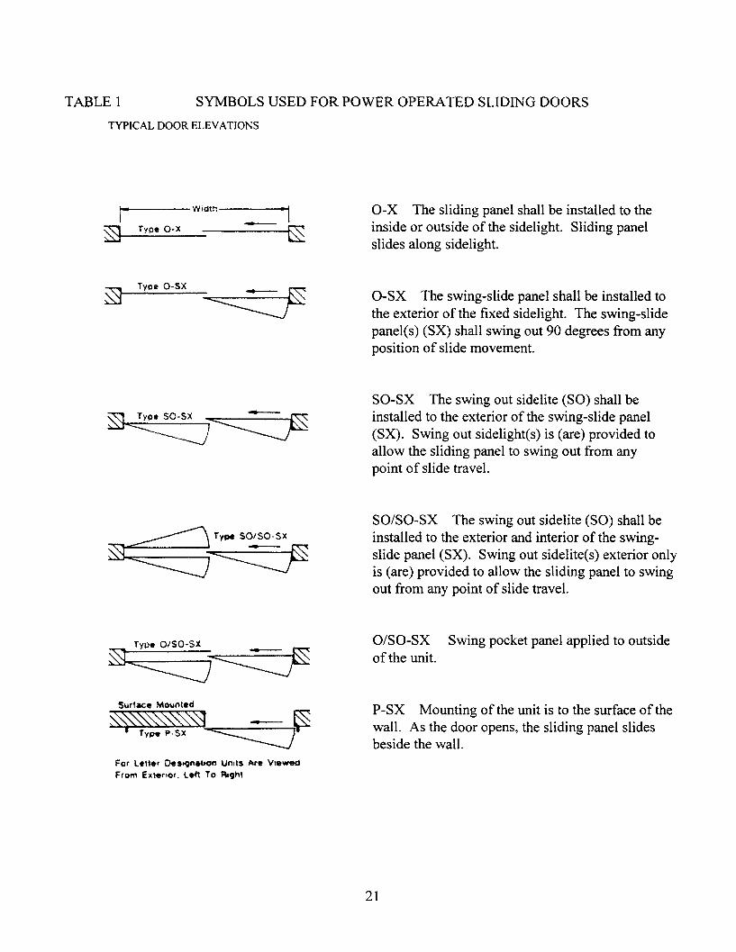
TABLE 1 SYMBOLS USED FOR POWER OPERATED SLIDING DOORS
TYPICAL DOOR ELEVATIONS
;..1--..----widtn-----\
~ T OX - ~~ ype· ~
~ TypeO-SX~
~ Type SO·SX~
~'
~ Type SO/SO-SX
~~
Surface !wlO\lnted
~~~~ -~Ty~P·SX ~
For Len.r o.s'9f\atlOf\ Un,ts A.re VI.WedFrom Ext.nor. Left To RighI
O-X The sliding panel shall be installed to theinside or outside of the sidelight. Sliding panelslides along sidelight.
O-SX The swing-slide panel shall be installed tothe exterior of the fixed sidelight. The swing-slidepanel(s) (SX) shall swing out 90 degrees from anyposition of slide movement.
SO-SX The swing out sidelite (SO) shall beinstalled to the exterior of the swing-slide panel(SX). Swing out sidelight(s) is (are) provided toallow the sliding panel to swing out from anypoint of slide travel.
SO/SO-SX The swing out sidelite (SO) shall beinstalled to the exterior and interior of the swingslide panel (SX). Swing out sidelite(s) exterior onlyis (are) provided to allow the sliding panel to swingout from any point of slide travel.
O/SO-SX Swing pocket panel applied to outsideof the unit.
P-SX Mounting of the unit is to the surface of thewall. As the door opens, the sliding panel slidesbeside the wall.
21

TABLE I-A MINIMUM EXPOSED MAT SIZES FOR SWINGING DOORS (see 7.3.1 and 7.3.2) (inches)
Door Min. Width Activating Safety Mat Safety MatOpening Size Required Side - Min. Min. Length Min. Lengthinches (rom) inches (rom) Length 3" Threshold 1" Threshold
inches (rom) inches (rom) inches (mm)36 (915) 26 (660) 43 (1090) 36 % (935) 37 % (960)37 (940) 27 (685) 43 (1090) 36 % (935) 37 % (960) CENTER
42 (1065) 32 (815) 43 (1090) 42 % (1085) 43 % (1110) PIVOT43 (1090) 33 (840) 43 (1090) 42 % (1085) 43 % (1110) SINGLES44 (1120) 34 (865) 43 (1090) 44 % (1135) 45 % (1160)45 (1145) 35 (890) 43 (1090) 44 % (1135) 45 % (1160)48 (1220) 38 (965) 43 (1090) 48 % (1240) 49 % (1265)49 (1245) 39 (990) 43 (1090) 48 % (1240) 49 % (1265)
48 (1220) 38 (965) 43 (1090) 24 % (630) 25 % (655) CENTER50 (1270) 40 (1015) 43 (1090) 24 % (630) 25 % (655) PIVOT60 (1525) 50 (1270) 43 (1090) 30 % (780) 31 % (805) PAIRS62 (1575) 52 (1320) 43 (1090) 30 % (780) 31 %(805)72 (1830) 62 (1575) 43 (1090) 36 % (935) 37 % (960)74 (1880) 64 (1625) 43 (1090) 36 % (935) 37 % (960)84 (2135) 74 (1880) 43 (1090) 42 % (1085) 43 %(1110)86 (2185) 76 (1930) 43 (1090) 42 % (1085) 43 % (1110)
36 (915) 26 (660) 43 (1090) 41 % (1060) 41 % (1060) BUTTS &42 (1065) 32 (815) 43 (1090) 47 % (1215) 47 % (1215) OFFSET44 (1120) 34 (865) 43 (1090) 49 % (1265) 49 % (1265) HUNG48 (1220) 38 (965) 43 (1090) 53 % (1365) 53 % (1365) SINGLES
48 (1220) 38 (965) 43 (1090) 29 % (755) 29 % (755) BUTTS &60 (1525) 50 (1270) 43 (1090) 35 % (910) 35 % (910) OFFSET72 (1830) 62 (1575) 43 (1090) 41 % (1060) 41 % (1060) HUNG84 (2135) 74 (1880) 43 (1090) 47 % (1215) 47 % (1215) PAIRS
22
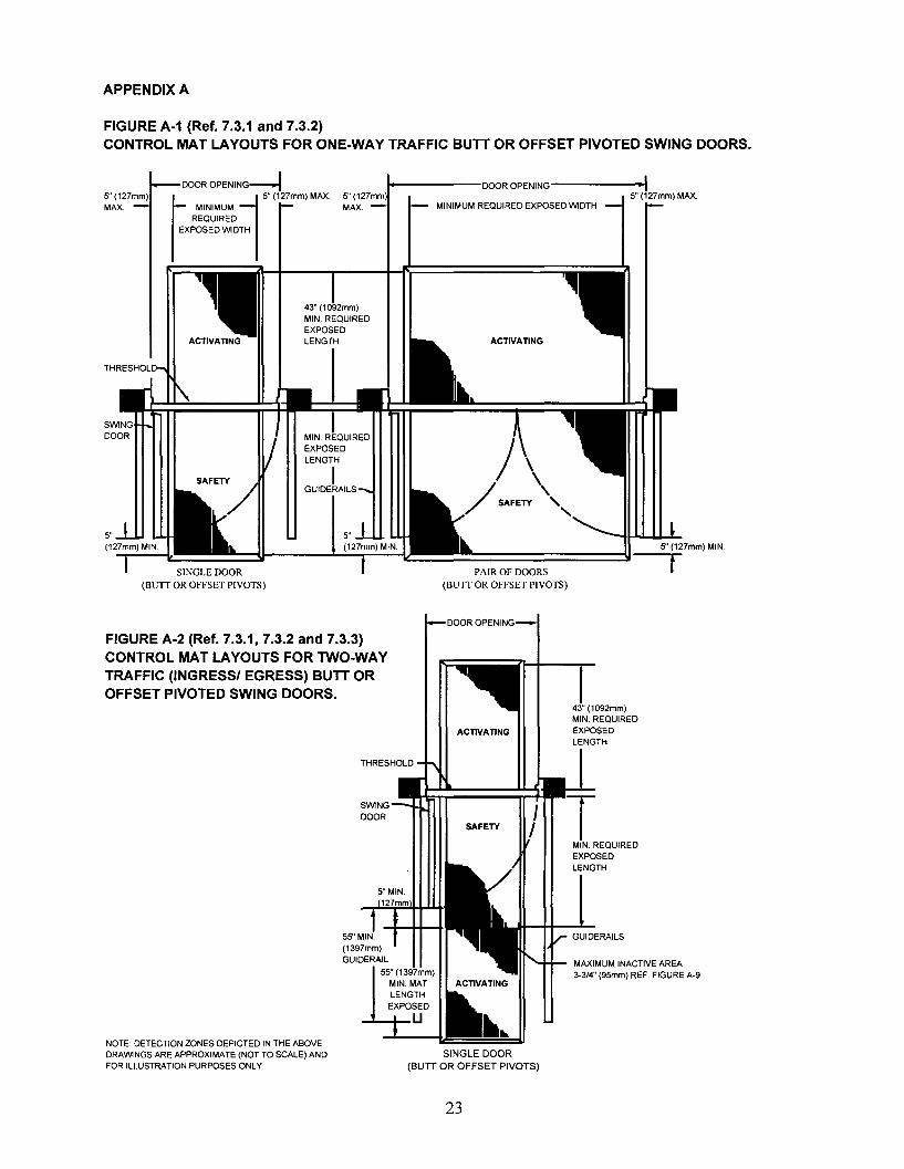
APPENDIX A
FIGURE A-1 (Ref. 7.3.1 and 7.3.2)CONTROL MAT LAYOUTS FOR ONE-WAY TRAFFIC BUTT OR OFFSET PIVOTED SWING DOORS.
ACTIVATING
1------000ROPENING-------.~I5" (127mm 5" (127mm) MAX.MAX. - MINIMUM REQUIRED EXPOSED WIDTH
ACTIVATING
SAFETY
DOOR OPENING-!
'" 15" (127mm) MAX.
MINIMUMREQUIRED
EXPOSED WIDTH
""i:;,;,:.;::;;,:,,:;,--I'~~~~=::::!If_---...L...:..:.:~~;;;;.;;-ll~~~~==========::Y~7mm) MIN.
PAIR OF DOORS I(BUIT OR OFFSET PIVOTS)
DOOR OPENING
FIGURE A-2 (Ref. 7.3.1, 7.3.2 and 7.3.3)CONTROL MAT LAYOUTS FOR TWO-WAYTRAFFIC (INGRESSI EGRESS) BUTT OROFFSET PIVOTED SWING DOORS.
ACTIVATING
43" (1092mm)MIN. REQUIREDEXPOSEDLENGTH
SINGLE DOOR(BUn OR OFFSET PIVOTS)
SWINGDOOR
NOTE DETECTION ZONES DEPICTED IN THE ABOVEDRAWINGS ARE APPROXIMATE (NOT TO SCALE) ANDFOR ILLUSTRATION PURPOSES ONLY.
SAFETYJI T
MIN. REQUIREDEXPOSEDLENGTH
GUIDERAILS
MAXIMUM INACTIVE AREA3-3/4" (95mm) REF. FIGURE A-9.
23
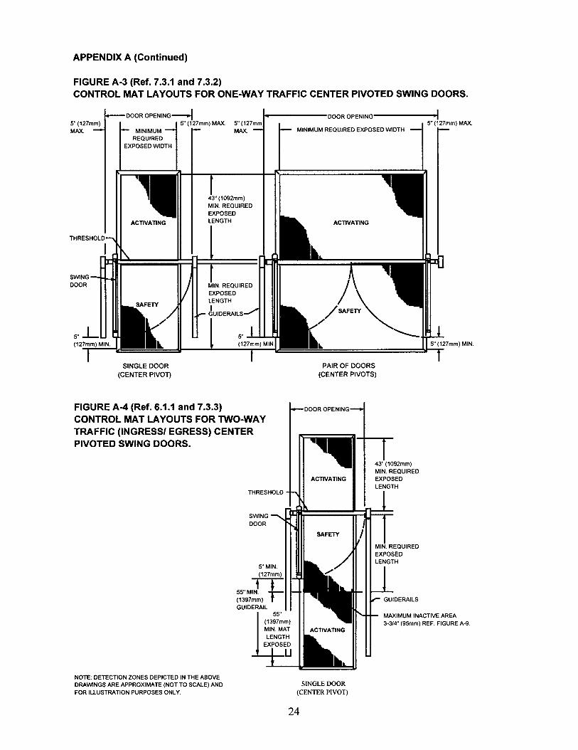
APPENDIX A (Continued)
FIGURE A-3 (Ref. 7.3.1 and 7.3.2)CONTROL MAT LAYOUTS FOR ONE-WAY TRAFFIC CENTER PIVOTED SWING DOORS.
ACTIVATING
MIN. REQUIREDEXPOSEDLENGTHI
GUIDERAILS
43" (1092mm)MIN. REQUIREDEXPOSEDLENGTHACTIVATING
DOOR OPENING-I I------DOOROPENING------~.I5" (127mm) MAX. 5" (127mm 5" (127mm) MAX.
MAX. MINIMUM REQUIRED EXPOSED WIDTH
SWINGDOOR
SINGLE DOOR(CENTER PIVon
PAIR OF DOORS(CENTER PIVOTS)
FIGURE A-4 (Ref. 6.1.1 and 7.3.3)CONTROL MAT LAYOUTS FOR TWO-WAYTRAFFIC (INGRESSI EGRESS) CENTERPIVOTED SWING DOORS.
SWINGDOOR
5"MIN.(127mm)
55"MJT(1397~~) rGUIDERAIL
MAXIMUM INACTIVE AREA3-3/4" (95mm) REF. FIGURE A-9.
NOTE: DETECTION ZONES DEPICTED IN THE ABOVEDRAWINGS ARE APPROXIMATE (NOT TO SCALE) ANDFOR ILLUSTRAnON PURPOSES ONLY.
SINGLE DOOR(CENTER PIVOT)
24
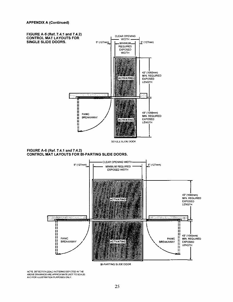
APPENDIX A (Continued)
43" (1092mm)MIN. REQUIREDEXPOSEDLENGTH
43" (1092mm)MIN. REQUIREDEXPOSEDLENGTH
5" (127mm
)PANIC /BREAKAWAY
~/
FIGURE A-5 (Ref. 7.4.1 and 7.4.2)CONTROL MAT LAYOUTS FORSINGLE SLIDE DOORS.
SINGLE SLIDE DOOR
FIGURE A-6 (Ref. 7.4.1 and 7.4.2)CONTROL MAT LAYOUTS FOR BI-PARTING SLIDE DOORS.
5" (127mm)
)PANIC /II BREAKAWAY /
II /II ~u--
5" (127mm)
43" (1092mm)MIN. REQUIREDEXPOSEDLENGTH
\ II
\IIII
" II 43" (1092mm)
\
PANIC II MIN. REQUIRED
BREAKAWAY II EXPOSED
" II LENGTH
''--J1 lBI-PARTING SLIDE DOOR
NOTE: DETECTION ZONE PATTERNS DEPICTED IN THEABOVE DRAWINGS ARE APPROXIMATE (NOT TO SCALE)AND FOR ILLUSTRATION PURPOSES ONLY.
25

APPENDIX A (Continued)
CONTROL MATS CROSS SECTIONS.
CROSS SECTION at THRESHOLD
2-112" (64mm) MAX. INACTIVEAREA WHEN MATS ARE
PERPENDICULAR TO OPENING
FIGUREA-7(Ref. 7.6.3)
FIGUREA-8(Ref. 7.6.1)
PLAN VIEW-PERPENDICULAR MATS
PLAN VIEW- PARALLEL MATS
CROSS SECTION A-A at JOINT
3-3/4" (95mm) MAX. INACTIVEAREA WHEN MATS AREPARALLEL TO OPENING
CROSS SECTION B-B at JOINT
FIGUREA-9(Ref. 7.6.2)
I-----EXPOSEDAREA-----1
MIN. RAMP LENGTH 1-112" (38mm ACTIVE 1-112" (38mm)
• !'C.•..••.. j
~CROSS SECTION at SURFACE MAT TRIM
NOTE: THE DRAWINGS DEPICTED ABOVE ARE APPROXIMATE(NOT TO SCALE) AND FOR ILLUSTRATION PURPOSES ONLY.
26
FIGURE A-10(Ref. 7.1, 7.6.4,and 7.7.4)

APPENDIX A (Continued)
FIGURE A-11 (Ref. 6.1)GUIDERAIL LAYOUTS FOR SWINGING DOORS.
ADJACENTWALL
ACTIVATING
6"(152mm)MAX.
be APPROACHSIDE
6"(152mm)MAX.
II
APPROACHSIDE
ACTIVATING
JAMB! FLOOR MOUNTED
PLAN VIEW- ONE-WAY TRAFFIC DOUBLESWING DOORS.
WIDTH OF DOOR_=hMINIMUM
~" (51mm) MAX.
30" (762mm)MIN.
IDIVIDER
SWINGDOOR
REFER TO FIGURE A-2 FOR GUIDERAIL LAYOUT INTWO-WAY TRAFFIC (INGRESS! EGRESS) APPLICATION(REF. A-12A and 6.1.1, EXCEPTION #2).
GUIDERAIL ELEVATIONS.
FREE STANDING! FLOOR MOUNTED
WIDTH OF DOOR-~
""'"0" m-T
111130" (762mm)MIN.
IPANEL
SWING DOOR ---t-
ISOMETRIC VIEW- ONE-WAY TRAFFICDOUBLE SWING DOORS.
NOTE: DETECTION ZONES DEPICTED IN THE ABOVEDRAWINGS ARE APPROXIMATE (NOT TO SCALE) ANDFOR ILLUSTRATION PURPOSES ONLY.
27
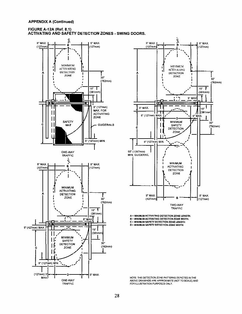
APPENDIX A (Continued)
FIGURE A-12A (Ref. 8.1)ACTIVATING AND SAFETY DETECTION ZONES - SWING DOORS.
ONE-WAYTRAFFIC
5" MAX.B ---+--1(127mm)
' .. '5"MAX.(127mmJ---lI---
5" MAX. It:- ,-.. - 15,,1,- -,
A= MINIMUM ACTIVATING DETECTION ZONE LENGTH.S = MINIMUM ACTIVATING DETECTION ZONE WIDTH.C = MINIMUM SAFETY DETECTION ZONE LENGTHD = MINIMUM SAFETY DETECTION ZONE WIDTH
.5" MAX ~--.....-t 5" MAX.
i(127mm-~..f .. _.. (127mm)
, . ," I ", I
\
I MINIMUM II ACTIVATING
A I DETECTION, II ZONE II I 30I , (762mm)
,\".. ' ,'--- "'1'5="T" " (381mm)
"-, ...-' 5"MAX t 11_.· ,L
NOTE: THE DETECTION ZONE PATTERNS DEPICTED IN THEABOVE DRAWINGS ARE APPROXIMATE (NOT TO SCALE) ANDFOR ILLUSTRATION PURPOSES ONLY,
TWO-WAYTRAFFIC
I, • J (381mm5" (127mm) MAX.,' D '\ 5"MU
II I MINIMUM lr 30"
SAFETY / (762mm)
~c L~~/:- '1
T 5" (127mm) MIN. '.. ,.... "',- :'):, <-' ", ,
55" (1397mm) , IMIN. GUIDERAIL' I
I \I ,I MINIMUM II ACTIVATING •
DETECTIONZONE, ,
" ,1\ ,
30"(762mm)
-.l..
I
~--rI 30": (762mm)
',",.'
MINIMUMACTIVATINGDETECTION
ZONE
.G-• 5" MAX.
B ----f-... (127mm)---~.....
,"- I -",
" I ", ,,,,IIII,..",
",
A
5" MAX.,I-_I--__(127mm
T
5" MAX ~ 5" MAX.(127 ') B --+--f(127mm)
Tmm
- (/" r·'\,, MINIMUMI ACTIVATING I
"--. ---,-A • DETECTION I, ZONE I 30"I ,I I (762mm), I
'\, ,,'-1ST(381mm)
5" (127mm) MAX.
r II,,', MINIMUM
II. SAFETY
II~ DETECTION ~c , ZONE / I111 11
\.-,,// ,'-
-1::p;"'MIN-'_._ =./1 i(",mm'5l=1===D~5. MAX
MAX.ONE-WAYTRAFFIC
28

APPENDIX A (Continued)
FIGURE A-12B (Ref. 8.1)ACTIVATING AND SAFETY DETECTION ZONES - SWING DOORS WITH DOOR MOUNTED SENSORS.
DOOR PIVOT
GUIDERAILS
S"MAX. S"MAX. S"MAX. S"MAX.(127mm) B (127mm) (127mm) B (127mm)
T...~... .J. ...
J11- -, -- - ..., £ \ I Ii \... ... , ...I , , ..., , ,
\MINIMUM
I
I I I MINIMUM
IACTIVATING , , ACTIVATING
A DETECTION 3D" A DETECTION,ZONE
, ,ZONE
3D"(762mm)
(762mm)\ I \
... 1S"1S"
" .... ,... ...(381mm)
... (381mm)\ ,
DOOR
PIVOT
S"MAX.
(127mm) t-....--
SWING DOOR IN
CLOSED POSITION
SAFETY DETECTION ZONES ARE SHOWN WITH THE SWINGDOOR IN THE FULL CLOSED AND FULL OPEN POSITIONS ONLY.
A = MINIMUM ACTIVATING DETECTION ZONE LENGTH.B = MINIMUM ACTIVATING DETECTION ZONE WIDTH.C = MINIMUM SAFETY DETECTION ZONE LENGTH.0= MINIMUM SAFETY DETECTION ZONE WIDTH.
NOTE: DETECTION ZONE PATIERNS DEPICTED IN THEABOVE DRAWINGS ARE APPROXIMATE (NOT TO SCALE)AND FOR ILLUSTRATION PURPOSES ONLY.
29
SWING DOOR IN OPEN
POSITION

APPENDIX A (Continued)
FIGURE A-13 (Ref. 8.2)ACTIVATING DETECTION ZONES - SLIDE DOORS.
SLIDINGPANEL
SLIDINGPANEL
I",I ",I ,\', ,\',, ", "
I ,"I ,II.Y~!!!!!!!!!I ,I ,, ,, ,, ,
5"MAX.'(127mm)
I,ct.
A = MINIMUM ACTIVATING DETECTION ZONE LENGTH.S = MINIMUM ACTIVATING DETECTION ZONE WIDTH.
II,,
.."
\...... ,
I
,.... ,
I,,
.... -
<
1----- B----~I
c""'=
15"(381mm .." I
L_
30"(762mm)
i-=- \
C )/'MINIMUM
AI ACTIVATINGDETECTION
ZONE
r" -, 15" (127mm) MAX.
rT~~----_...L_-'------~~~'r-f1L..tE - - - -- - "'T--~- -- - - =-r:H
_--:l,;..;L--:..'=-----II--.L,..;;:,Is" (127mm) MAX.FIXEDPANEL
MINIMUM30" ACTIVATING
DETECTION
J''t
mm
, \, ,_--::Z~O_N_E=--,_,_",_'_'/ TWO-WAY TRAFFIC
REFER TO 8.2.3 FORONE-WAY TRAFFIC
1---- B ----INOTE THE DETECTION ZONE PAITERNS DEPICTED IN THE ABOVEDRAWINGS ARE APPROXIMATE (NOT TO SCALE) AND FOR ILLUSTRATIONPURPOSES ONLY
30

APPENDIX A (Continued)
FOLDING DOORS PANEL LAYOUTFigure A-14
(Ref. 5.0)
SINGLE FOLDING DOOR
FX FS
FS = FOLD SWING PANEL
FX = FOLD SLIDE PANEL
PAIR OF FOLDING DOORS
FS FX
--
r; /.
11:/,
I /. ,I
II~ ,
/.
~ ~i r-: I . F=
"'""J J Lil-F
GUIDE RAIL LAYOUTS FOR FOLDING DOORS
Figure A-15(Ref. 62)
SINGLE FOLDING DOOR
II
I Guide RoilI (One Req' don Hinge Side)
PAIR OF FOLDING DOORS
12 inches, (305mm), for Two Way
Traffic or One Way Trafficapproaching from the Fold Side.
or
5 inches, (130 mm), for One Way
Traffic approaching from theNon-Fold Side.
Door Jamb
Width of FS Leaf plus "A"
Panel orDivider
fI
30" Min.
I
JAMB AND FLOOR MOUNTED FREE STANDING FLOOR MOUNTED
31
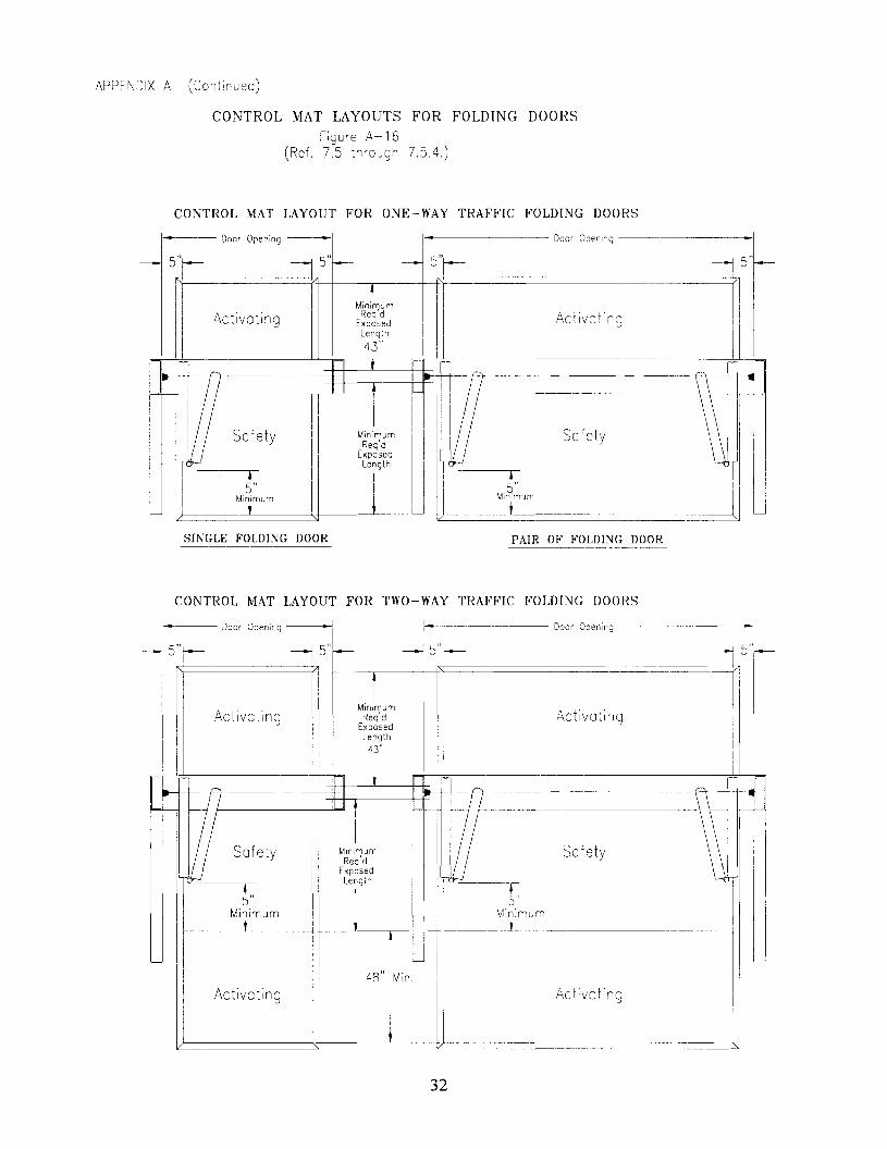
APPENDIX A (Continued)
CONTROL MAT LAYOUTS FOR FOLDING DOORSFigure A-16
(Ref. 7.5 through 7.5.4.)
CONTROL MAT LAYOUT FOR ONE-WAY TRAFFIC FOLDING DOORS
SafetySafety
Door opening-I
5"
I---rI Minimum
I t,)---
I------~Door Opening -- ·1
5l- 45"~R============:(:f-----+-------.----~==-==---========----=:=--~-.. I
Activating Activating: I
~-~---_._--~
5"-
SINGLE FOLDING DOOR PAIR OF FOLDING DOOR
CONTROL MAT LAYOUT FOR TWO-WAY TRAFFIC FOLDING DOORS
1-·------- Door Opening
15"1~. r-- - -1I
rMinimumI Activat':ng IReg'd Activating I I
1
Exposed. ILength
!! ITI il,0 II II IF
~
USolety
- II
?- - --- J~
ILJI F
1r-
I IMinimumI Safety
Req'dExposedLength I-(
I!
I
1
I
I5" I 5" I
Minimum I
-IMinimum
III I ,
I
I i r- L.- III 48"I
Min.
iActivating
I
ActivatingII
IJI t
_
' 4 Door Opening
5"1---
32

APPENDIX A (Continued)
DETECTION PATTERN LAYOUTS FOR FOLDING DOORSFigure A--17A
(Ref. 8.3 through 8.3.6.)
ONE WAY TRAFFIC WITH APPROACH FROM NON-FOLD SIDE
II
SofetyMot
----..jFOLDING DOOR
J"5 Max." -n-' ,---- ~
: : ;{" I'/:/ I Minimum Safety \: :,' / Detection Area
or: ",L j J.L ------ --l -----
SINGLE FOLDING DOOR
ONE WAY TRAFFIC ONE WAY TRAFFIC
WITH DOORS CLOSED
I\ 5" )
I" MimmUmj----, ./"
5'~ - S"
SINGLE FOLDING DOOR
I-Door Opening =1
5'MoaJ ~43"
~nt,mum_________ I
-(-,- -~-
-\- - --)I ~ ~/
15"
Minimum
SofetyMot
-~ S"I~ ----..j s"f--SINGLE FOLDING DOOR
1---- Door Opening ---1'I
s'Mo-x- s'Mox I~ S'Mox43" Minimum -
3
10" I Y-./" - - ~)1- _Areo -
-\- - - / -~
I ~ -~ I 15", ?a~ n
ONE WAY TRAmC ONE WAY TRAFFIC
WITH DOORS OPEN
33

APPENDIX A (Continued)
DETECTION PATTERN LAYOUTS FOR FOLDING DOORSFigure A-17B
(Ref. 83 through 83.6)
\ \ I I--........~\\II
Minimum Safety \~'Detedan Area
"'----- J:~um / I----- -----L-~-~ d-- -J d---
PAIR OF FOLDING DOORS
O~E WAY TRAFFiC ONE WAY TRAFFIC
WITH DOORS CLOSED
SafetyMot
PAIR OF FOLDING DOORS
r------- Door Opening "I
Minimum SafetyDetection Area
/(
I'" 5""" Minimum /
L ----- ~l ------5"
ONE WAY TRAFFIC
~' II:II; II I 5".h--"L" .
---15"~ PAIR OF FOLDING DOORS
ONE WAY TRAFFIC
WITH DOORS OPEN
34

APPENDIX A (Continued)
DETECTION PATTERN LAYOUTS FOR FOLDING DOORS
Figure A-17C (Ref. 8.3 thiOcJgh 8.3.6)
SINGLE FOLDING DOOR
TWO WAY TRAFFIC
PAIR OF FOLDING DOORS
TWO WAY TRAFFiC
SINGLE FOLDING DOOR
TWO WAY TRAFF'C
PAIR OF FOLDING DOORS
TWO WAY ~RMTIC
Minimum ActivationJetection Area
J--s-'"c+1J"'=Lk ~ ==11 ==-= ==-3:'Ur---,-r=tlErl=_
MaxI ---+ --1--- "" 1---+-----'-----r---+I I I I M,nlmum \ I
9=1 , D;~:~;:on I : nt!I
s" . s,,1 \ Area LI s,L- I I
M'~ 1+"----TIl r-tl/ ---------~ "5" I U ~
S"M~--t M,n,mum !\ct;vo;;;;;-\ - -~--+-=J ~ts"-Detecteon Area 3u 48, Max
----.L- , M n mum
~~---/ I -~
____ ---- I -----
WITH DOORS OPEN
35

APPENDIX A (Continued)
DETECTION PATTERN LAYOUTS FOR FOLDING DOORS
Figure A-17D (Ref. 8.3.2.1)
ONE WAY TRAFFIC WITH APPROACH FROM FOLD SIDE
SINGLE FOLDING DOOR
ONE WAY ~RAFF'C
~-_.
WITH DOORS CLOSED
SINGLE FOLDING DOOR
ONE WAY TRAFFIC
PAIR OF FOLDING DOORS
ONE WAY TRAF~IC
-------------
PAIR OF FOLDING DOORS
ONE WAY TRAFFIC
WITH DOORS OPEN
36

APPENDIX A (Continued)
A-18A (Ref. 8.2.1 and 8.2.2.1) VERTICAL SECTION - SLIDE DOOR SHOWINGACTIVATING DETECTION AND PHOTOELECTRIC BEAM ZONES.
ACTIVATING ---DETECTION ZONE·1.5 SECOND MIN.TIME DELAY
SLIDINGDOOR PANEL
3" (76mm) MAX. FROMCENTERLINE OF SLIDINGPANEL (REF. 8.2.2.1).
TOPPHOTOELECTRICBEAM LOCATEDBETWEEN55" (1397mm) AND45" (1143mm)
BOTTOMPHOTOELECTRICBEAM LOCATEDBETWEEN 28"(711mm) AND6" (152mm)
A =MAXIMUM DISTANCE TO ACTIVATINGDETECTION ZONE (REF. 8.2.1).
A-18B (Ref. 8.2.1 and 8.2.2.2) VERTICAL SECTION - SLIDE DOOR SHOWINGACTIVATING AND PRESENCE DETECTION ZONES.
ACTIVATING --__
DETECTION ZONE
PRESENCE --___
DETECTION ZONE
NOTE: DETECTION ZONE PATIERNS DEPICTED IN THEABOVE DRAWINGS ARE APPROXIMATE (NOT TO SCALE)AND FOR ILLUSTRATION PURPOSES ONLY.
NOTE: BOTTOM PHOTOELECTRICBEAM (SHOWN IN DRAWING A-18A)REQUIRED IF PRESENCE DETECTIONZONE IS DEACTIVATED WHEN DOORSTARTS TO CLOSE ( REF. 8.2.2.2 (2».
A = MAXIMUM DISTANCE TO ACTIVATING DETECTIONZONE (REF. 8.2.1).B =MINIMUM PRESENCE DETECTION ZONE WIDTH(REF. 8.2.2.2 (1».
37

APPENDIX A (Continued)
A-18C (Ref. 8.2.1 &8.2.2.3) VERTICAL SECTION - SLIDE DOOR SHOWING ACTIVATINGAND PRESENCE DETECTION ZONES.
PRESENCE DETECTIONZONE (VARIABLE)
SLIDING DOORPANEL
A = MAXIMUM DISTANCE TO ACTIVATING DETECTION ZONE (REF. 8.2.1).B = MAXIMUM DISTANCE TO PRESENCE DETECTION ZONE (REF. 8.2.2.3 (1».
NOTE: DETECTION ZONE PATTERNS DEPICTED IN THEABOVE DRAWINGS ARE APPROXIMATE (NOT TO SCALE)AND FOR ILLUSTRATION PURPOSES ONLY.
38

APPENDIX B
FIGURE B-1 (Ref. 11.)SIGNAGE FOR AUTOMATIC SLIDE DOORS.
DECAL FOR ALLAUTOMATIC DOORS
® ~ AUTOMATIC DOOR ~
DECAL FOR'KNOWINGACT DOORS'
DECAL FOR SLIDINGDOORS WITHSWINGING PANELS
®
©
AUTOMATIC DOORACTIVATE SWITCH
TO OPERATE
IN EMERGENCYPUSH TO OPEN
FIGURE B-2 (Ref. 11.)INTERIOR VIEW - AUTOMATIC SLIDE DOOR WITH APPROPRIATE SIGNAGE FOR TWO-WAYTRAFFIC CONTROL.
/ ", '-
/ / " "/ / " "/ / "- "/ / "- "/ / , ,/
~ ,"liN EMERGENCY I® @I IN EMERGENCY I~ .- - -_.
/ PUSH TO OPEN C PUSH TO OPEN .-
/ @Or@) ~,-,..". I ,, ,
l.- I I ~,-,..". t3> Or@ I()
. , .,~ ~t', '" ~ ~ / "DECAL CENTERED,
" / BElWEEN 36" MIN.," / AND 60" MAX. (914
AND 1524mm) ABOVE," / FINISH FLOOR," / /
SO "SX " / sx l/ SO
PANEL " PANEL , / PANEL / PANEL
"- I /
NOTE: THE DRAWINGS DEPICTED ABOVE ARE APPROXIMATE(NOT TO SCALE) AND FOR ILLUSTRATION PURPOSES ONLY.
39
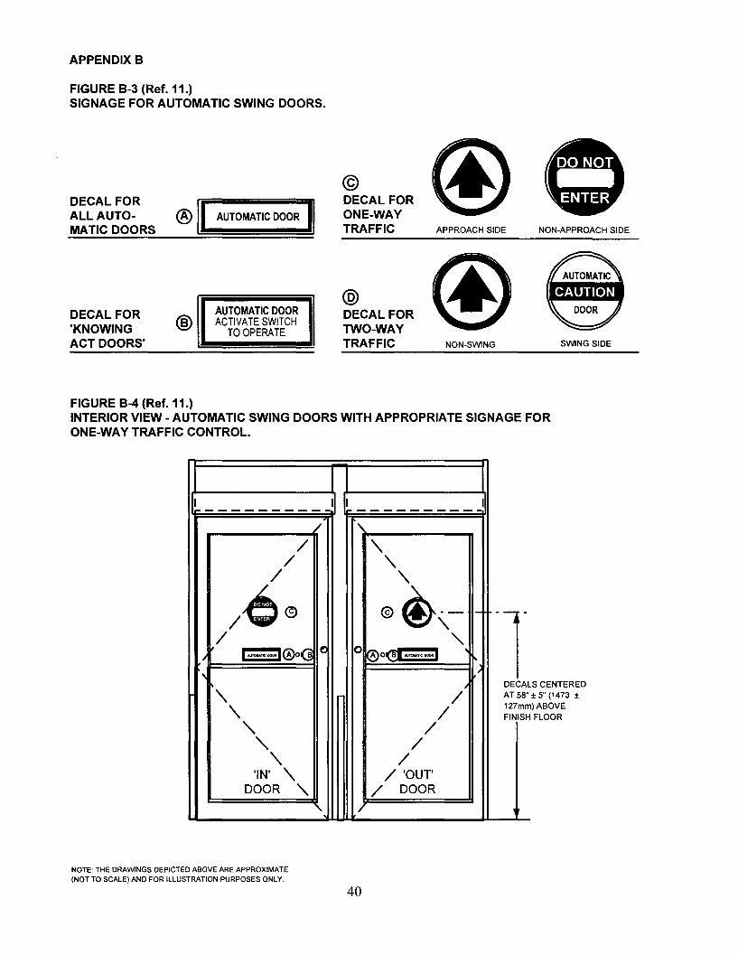
APPENDIX 8
FIGURE 8-3 (Ref. 11.)SIGNAGE FOR AUTOMATIC SWING DOORS.
DECAL FORALL AUTOMATIC DOORS
® AUTOMATIC DOOR
©DECAL FORONE-WAYTRAFFIC APPROACH SIDE
WiL~TERNON-APPROACH SIDE
DECAL FOR'KNOWINGACT DOORS'
®AUTOMATIC DOORACTIVATE SWITCH
TO OPERATE
@DECAL FORTWO-WAYTRAFFIC NON-SWING SWING SIDE
FIGURE 8-4 (Ref. 11.)INTERIOR VIEW - AUTOMATIC SWING DOORS WITH APPROPRIATE SIGNAGE FORONE-WAY TRAFFIC CONTROL.
LS CENTERED± 5" (1473 ±) ABOVEFLOOR
II I I I--------- ----------
/.,
/ '\/ '\
/ '\
/e® ®@,- 1-
-T,,/I~ "-
I NJT*,nc DOORl@o~ 0 @O(!i '",_oc_. ,I
,~'\ /1 DECA
AT 58"
'\ /127mmFINISH
'\ /'\ /
'\ /'IN' '\ / 'OUT
DOOR "- / DOOR, 1
NOTE: THE DRAWINGS DEPICTED ABOVE ARE APPROXIMATE(NOT TO SCALE) AND FOR ILLUSTRATION PURPOSES ONLY.
40

APPENDIX B
FIGURE B-5 (Ref. 11.)SIGNAGE FOR AUTOMATIC FOLDING DOORS.
® I AUTOMATIC DOOR ~
DECAL FORALL AUTOMATIC DOORS
DECAL FOR'KNOWING @ACT DOORS'
DECAL FORFOLDING DOORSWITH SWINGING ©PANELS
AUTOMATIC DOORACTIVATE SWITCH
TO OPERATE
IN EMERGENCYPUSH TO OPEN
@DECAL FORONE-WAYTRAFFIC
®DECAL FORTWO-WAYTRAFFIC
APPROACH SIDE
NON-FOLD SIDE
NON-APPROACH SIDE
FOLD SIDE
FIGURE B-6 (Ref. 11.)INTERIOR VIEW (FOLD SIDE) - TYPICAL FOLDING DOOR WITH APPROPRIATE SIGNAGE FORTWO-WAY TRAFFIC.
NTERED36" MIN.
MAX. (914m)ABOVEOR
/ "/ ,/ ,
/ ,/ ,
/ "L/,*@ ®~"r- ---" - .. "/ DOOR (C) (C) DOOR "" "" I ~~:~~~G~~~~ I 1~~:~~~G~~~~ 1_ "/ --,- "r/ ~I-..-~® ~
,/ A"'I AlITwu.nc DOOIllra "
NTERED" ~ ~
/ DECALCE(1473 ± " / BElWEENOVE " /
AND 60"" "OR " " AND 1524m,// FINISH FLO,
, /
" /
FS 'fX F~/ FSPANEL PA~L PANEL PANEL,
"" "
DECALSCEAT 58" ± 5"127mm)ABFINISH FLO
NOTE: THE DRAWINGS DEPICTED ABOVE ARE APPROXIMATE(NOT TO SCALE) AND FOR ILLUSTRATION PURPOSES ONLY.
41

APPENDIX C (Not a part of ANSIIBHMA A156.10)
DEFINITIONS OF TERMS AS USED IN THE POWER OPERATED DOOR INDUSTRY.
Air Lock.. Air space between doors such as in a vestibule where only one door or set of doors can beopened at one time.
Approach Beam. Photo-electric control beam used to actuate an automatic door.
A device connecting the door operator to the door. It is concealed, semi-concealed or surfaceArm.applied.
Automatic Entrance Package. Complete entrance way containing door(s), frame, controls, and automaticoperator.
Bi-Parting Sliding Doors. A pair of door leaves sliding away from each other to form a single commondoor opening.
Bottom Arm (Hardware). The arm mechanism attached to the bottom rail of a door and connecting to thespindle of a floor closer, pivot or automatic door operator.
Concealed Mounting. Automatic door operators which are mounted above or below the door andpower the door through the pivot or arm.
Cover Plate. In reference to door hardware, a finish plate used to cover the exposed face of a floor closernot covered by the threshold; also a plate used to cover the exposed face of a closer or automatic dooroperator mounted in the head of the door frame.
Door Arm. A device which is usually located in the top or bottom rail of a swinging automatic door. Thefunction of this device is to provide suitable connection of the automatic door operator to the door.
Door Light. The glass area in a glazed door.
Door Size (Actual). For swinging or sliding doors, the actual width and height of the door leaf itself.
Flush Glazing. A method of setting glass whereby glazing beads are recessed and flushed withthe edge of the frame.
Guard Bar. A protective bar applied to the lower portion of a door or sidelight to prevent collision with theglass.
Harness. A combination of wires and connectors providing connection of electrical controls to operatingequipment.
"In" Door. An automatic door installation designed for traffic into a building, space, etc.
In-Header Operator. A door operator completely contained in the door header requiring only electric,pneumatic or hydraulic power.
Left Hand Traffic. The traffic routing when the entrance door is placed to the left of adjacent exit doors asviewed from the outside.
Lintel A horizontal structural member spanning an opening at its head to carry construction above the opening.
Masonry Opening. The wall opening into which the door is installed.
42

An automatic operator in which the actuator and the power unit are made as a
Meeting Stile. The vertical edge of a door or window, in a pair, which is adjacent to the other door orwindow. A parallel meeting stile is one which has a beveled edge paralleling the edge of the door. A roundmeeting stile is one having a rounded edge.
Opening Cycle. Movement of a swinging or sliding door from closed position to fully open. Forswinging doors, this is normally 90 degrees.
"Out" Door. An automatic door installation designed for traffic out ofa building or space.
Photoelectric ControL A device which employs the use of a visible or invisible light beam across orthrough an opening. When the beam is interrupted by a person or object, a signal is generated.
Power Closing. The closing of a door by energy supplied from hydraulics, pneumatics or electricity.
Power Open. The opening of a door by energy supplied by other than manual means.
Power Unit A remote mechanical device used to convert energy (usually electrical) to pneumatic,hydraulic, or mechanical energy for transmission to the actuator.
Pressure Relief. A safety device to guard against excessive pressure buildup. Usually with reference topneumatic or hydraulic systems.
Prismatic. Prismatic doors are used to identify bi-parting sliding doors that meet at an inside angle oflessthan 180 degrees.
Pull Cord Switch. A switch located above the doorway having a cord with handle extending down toapproximately 6 feet above the floor. When the cord is pulled, a switch is closed and a signal generatedwhich can be used to actuate an automatic door operator.
Recessed Frame (Setting Frame). A frame set into the floor during construction which secures mats into aframe provide flush condition between floor and mat surface.
Recycle. A mode of operation of an automatic door operator that occurs when the door is in the closingportion of its travel and is actuated causing the door to immediately reverse and go to the open position.
Right Hand Traffic. The traffic routing when the entrance door is placed to the right of adjacent exit doors asviewed from the outside.
Self-contained Operator.single unit.
Sequential or Latching Operation. Operation ofpush switch to actuate and push switch to de-actuate.
Setting Blocks. Small pieces of neoprene, lead or other material which are placed under the lower edgeofa sheet ofglass to support it within a frame.
Single Slide Automatic Door. An automatic door which has one sliding leaf, either left hand or righthand.
Sliding Left Hand Automatic Door. Automatic sliding doors are said to be left hand when the door is viewedfrom the break out side of the opening and it travels to the left side of the viewer to open.
Sliding Right Hand Automatic Door. Automatic sliding doors are said to be right hand when the door isviewed from the break out side of the opening and it travels to the right side of the viewer to open.
Spring Closing The closing ofa door by energy supplied by springs.
Strike. An opening or retaining device provided in a frame, threshold or in the edge of a stile of an inactivedoor to receive a lock or latch bolt. (Also referred to as a Keeper or Strike Plate).
43

Synchronized Operators. Operators connected together either mechanically or electrically for simultaneousoperation. (Synonyms - coactive, simultaneous.)
Trim, Recessed Mat. Material installed around the perimeter of a control mat securing it recessed into thefloor.
Unknowing Act. Actuating a door operator, such as pressing a switch, without specific knowledge of howit is done or what will happen.
Variable Time Delay. A device which is adjusted to change the time a door remains open, after removal of theopen signal.
Visible Mounting. Automatic door operators which are mounted above the door, protruding from the wall,and drive the door with a visible bracket and arm are said to be visibly mounted.
Definitions of other terms are found in the American National Standard for Nomenclature for Steel Doors andSteel Door Frames, ANSI A123.1 and in the other ANSI/BHMA A156 Series of Standards.
APPENDIX D (Not a part of ANSIIBHMA A156.10)
Dl. REFERENCE TO OTHER STANDARDS
D1.1 When power operated fire doors are used, they are subject to the requirements of the Standard forFire Doors and Windows ANSIINFPA 80.*
Dl.2 Glazing in doors are subject to criteria in the Standard, Performance Specifications and Methods ofTest for Safety Glazing Material Used in Buildings, ANSI Z97.l * or CPSC requirements.
D1.3 Where required by the authority having jurisdiction, products meeting the requirements of thisStandard are also required to comply with Chapter 5, Means of Egress, of the Code for Safety from Fire inBuildings and Structures. ANSIINFPA 101.*
D1.4 Where required by the authority having jurisdiction, products meeting the requirements ofthis Standard are required to comply with UL 325** and be listed or labeled by a nationally recognizedindependent testing laboratory and be under a periodic examination service.
D1.5 Products meeting the requirements of this Standard shall also comply with applicable localbuilding code requirements.
APPENDIX E (NOT A PART OF ANSIIBHMA A156.10)
E-l CONFORMANCE CRITERIA
Certification that products offered meet the requirements of this Standard and conform to individualmanufacturer's drawings, specifications, standards and quality assurance practices are available and in somecircumstances are required. Buyer requirements determine the need for proof of conformance such as firstarticle inspection, test laboratory reports, or listings. Specifiers requiring assertions of conformance utilizestatements of conformance by individual manufacturers, or test reports acceptable to the buyer.
E-2 PRESERVATION, PACKAGING AND PACKING
Unless other arrangements between buyer and seller are made, preservation, packaging and packingshall be sufficient to protect containers and their contents under normal shipping and handling conditionsfrom the source of supply to the destination point.
E-3 MARKING
44

Unless other arrangements between buyer and seller are made, marking shall be in accordance with theindividual manufacturer's standard practice.
* Available from the American National Standards Institute, Inc., 11 West 42nd Street, New York, NewYork 10036.
**Available from Underwriters Laboratories, Inc., 333 pfingsten Road, Northbrook, IL 60662.
45

ANSIIBHMA A156.10-2005Revision of:
ANSI /BHMA A156.10-1999
AMERICAN NATIONAL STANDARD
FOR
POWER OPERATED PEDESTRIAN DOORS
[BHMAbuilders hardware manufacturers association
SPONSOR
BUILDERS HARDWARE MANUFACTURERS ASSOCIATION, INC.
Approved 9/20/2005AMERICAN NATIONAL STANDARDS INSTITUTE, INC.

AMERICAN NATIONAL STANDARD
An American National Standard implies a consensus of those substantially concerned with its scope andprovisions. An American National Standard is intended as a guide to aid the manufacturer, the consumerand the general public. The existence of an American National Standard does not in any respect precludeanyone, whether he has approved the standard or not, from manufacturing, marketing, purchasing, or usingproducts, processes, or procedures not conforming to this standard. American National Standards aresubject to periodic review and users are cautioned to obtain the latest editions.
CAUTION NOTICE: This American National Standard is permitted to be revised or withdrawn at anytime. The procedures of the American National Standards Institute require that action be taken to reaffirm,revise, or withdraw this standard no later than five years from the date of publication. Purchasers ofAmerican National Standards receive current information on all standards by calling or writing theAmerican National Standards Institute.
Published byBUILDERS HARDWARE MANUFACTURERS ASSOCIATION, INC.
355 Lexington Avenue New York, New York 100I7
Copyright © 2005 by theBuilders Hardware Manufacturers Association, Inc.
www.buildershardware.com
Not to be reproduced without specific authorization from BHMA
Printed in the USA
This Standard was approved by ANSI under the Canvass Method. BHMA was accredited on 21 March1983 by ANSI as a sponsor using the Canvass Method.
2

FOREWORD (This Foreword is not a part ofANSI/BHMA AI56.10)
The gcncral classification of builders hardware includes a wide variety of itemswhich are divided into several categories. To recognize this diversity, a sectionalclassification system has been established. Power Operated Doors is one suchsection and this Standard is a result of the collective efforts of members of theBuilders Hardware Manufacturers Association, Inc. who manufacture this product.The total Product Standards effort is, therefore, a collection of sections, eachcovering a specific category of items.
Performance tests and, where necessary, dimensional requirements have beenestablished to ensure a degree of safety. Thcre are no restrictions on design exceptfor those dimensional requirements imposed for reasons of safety.
This Standard is not intended to obstruct but rather to encourage the development ofimproved products, methods and materials. The BHMA recognizes that errors willbe found, items will become obsolete, and new products, methods and materials willbe developed. With this in mind, the Association plans to update, correct and revisethese Standards on a regular basis. It shall also be the responsibility ofmanufacturers to request such appropriate revisions.
ORDERING INFORMATION
BHMA standards, publications, and matchplates can be ordered at:
www.buildershardware.com - Search entire catalog, order printed or electronicversions, and download electronic versions right to your computer.
CaIl our Fulfillment Partner, Techstreet, at:
Toll-free (800) 699-9277 (US. and Canada)Ph. (734) 913-3930 Fax (734) 913-3946E-mail: techstreet.serviceilvthomson.com
Send mail to:BHMA c/o Techstreet777 E. Eisenhower ParkwayAnn Arbor, MI 48108 USA
3

TABLE OF CONTENTS
1. GENERAL 5
2. DEFINITlONS OF TERMS USED IN THIS STANDARD 6
3. SWINGING DOORS 8
4. SLIDING DOORS 8
5. FOLDING DOORS 9
6. GUIDE RAILS 8
7. CONTROL MATS REQUIREMENTS 9
8. SENSORS 12
9. KNOWING ACT DOOR ACTrvATlON 15
10. ENTRAPMENT PROTECTION 17
11. SIGNAGE 18
12. BREAK AWAY EGRESS TEST FOR SWINGING, FOLDING AND SLIDING DOORS 19
Table I - SYMBOLS USED FOR POWER OPERATED SLIDINGDOORS 23
APPENDIX A 25
APPENDIX B 44
APPENDIX C .47
APPENDIX D 49
APPENDIX E 49
4

1. GENERAL
l.l Scope Requirements in this Standard apply to power operated doors for pedestrian use whichopen automatically when approached by pedestrians and some small vehicular traffic or by a knowingact. Included are provisions to reduce the chance of user injury or entrapment. Power operated doorsfor industrial or trained tramc are not covered in this Standard.
1.1.1 Where this Standard contains specifications relating to minimum or maximum dimensions ofvarious components of power operated doors for pedestrian use and some small vehicular traffic, suchdimensions are included to provide user protection for what are, in the industry, standard applicationconditions. This Standard does not apply to custom installations.
1.2 This Standard does not apply to power assist and low energy power operated doors. Refer toANSI/BHMA A 156.19 for Power Assist and Low Energy Power Operated Doors.
1.3 Required dimensions are expressed in US units first; approximate metric equivalents follow inparentheses. The following is a conversion chart for inches to approximate mm equivalents where notgiven in the standard.
TO CONVERT INCHES TO MILLIMETERS, MULTTPLY INCHES BY 25.4TO CONVERT MILLIMETERS TO INCHES, MULTIPLY MILLIMETERS BY 0.03937.
Inches mm Inches mm Inches mm Tnches mm
1/16 1.6 6 152 23 584 45 11431/4 6.35 7 178 24 610 47 11941/2 12.7 8 203 25 635 48 12193/4 19 9 229 26 660 49 1245
I 25.4 10 254 27 686 50 1270I 1/2 38 II 279 28 7/1 51 1295I 3/4 45 12 304 30 762 52 1321I 1/2 38 13 330 31 787 53 1346
2 51 14 356 32 813 54 13722.26 57 15 381 33 838 55 139721/2 63 16 406 34 864 56 1422
3 76 17 432 36 914 57 14483 3/4 95 20 508 40 1016 58 1473
4 102 21 533 41 1041 60 15245 127 ..,,, 559 43 1092 144 3658
1.4 American National Standards referenced in A156.10 are available from BHMA,www.buildershardware.com or the American National Standards Institute, 25 West 43rd Street, NewYork, NY 10036. ASTM Standards referenced in A156.10 are available from ASTM, 100 BarrHarbor Dr., West Conshohocken, PA 19428-2959.
1.5 Tolerances Where only minus tolerances are given, the dimensions are permitted to beexceeded at the option of the manufacturers. All values which do not carry specific tolerances or arenot marked maximum or minimum shall have the following tolerances: Linear dimensions shall be ±1/16 in (1.6 mm). Pounds or pound force shall be ±2%. Degrees opening shall be ±2 degrees.Electrical measurements shall be ±2%.
5
1.6 Tests described in this standard are performed under laboratory conditions. Measurements shallbe taken under neutral air pressure conditions. In actual usage, results vary because of installation.maintenance and environmental conditions.
1.7 Doors used as fire doors or smoke barriers have additional requirements not covered in thisstandard.
1.8 Where required by the authority having jurisdiction, products meeting the requirements of thisStandard are required to comply with UL 325-Fifth Edition June 2002, and be listed or labeled by anationally recognized independent testing laboratory and be under a periodic examination service.
1.9 Tests described in paragraphs 7.6 and 12 shall be performed under the supervision of a nationallyrecognized independent testing laboratory on preproduction samples prior to acceptance of the designfor production and subsequent installation. Production units shall be lUlder an in-plant follow-upinspection service.
2. DEFINITIONS OF TERMS USED IN TillS STANDARD
2.1 Active Area The area where a sensor or control mat detects presence or motion.2.2 Activating Zone An area created by a sensor or control mat such that the door will open whenthe area is entered by (a) person(s) .2.3 Activating Zone, Secondary An area created by a sensor or control mat such that the door willreactivate or reverse and remain active until the door is almost closed.2.4 Automatic Door Operator A power operated mechanism that is attached to a door for thepurpose of mechanically opening and closing a door upon the receipt of an activating signal.2.5 Back Check The checking or slowing down of the speed of door opening before being fullyopened. (Also called Open Check.)2.6 Balanced Door A door equipped with a hinge which moves the hinge pivot point from the hingestile of the door towards the centerline of the door.2.7 Break Away Device A safety device other than an exit device that permits egress underemergency conditions. (Also called Emergency Release.)2.8 Break Out The process of activating a break away device causing the door or panel to swing inthe direction of egress.2.9 Center Pivoted A door which has the pivot point of the hinge located on the centerline of thedoor thickness.2.10 Clear Opening for Automatic DoorsNote: The following is for the purpose of sizing activating and safety zones. Refer to applicablebuilding codes for means of egress clear width requirements.
Swing Doors With the door open 90 degrees, the clear opening is measured between the face ofthe door and jamb or jamb stop.
Pair of Swing doors With the doors open 90 degrees the clear opening is measured between thefaces ofthe two open doors.
Sliding or Folding Doors In the fully opened position, the clear opening is measured from theedge of the leading stile to the jamb or jamb stop ifpresent.
Pair of Sliding or Folding Doors In the fully opened position, the clear opening is measuredbetween the edges of the leading stiles of the two doors.2.11 Closing Cycle Movement of a swinging, folding or sliding door from the fully open position tothe fully closed position.2.12 Closing Time Time from starting of a door closing until it is at rest fully closed.
6

2.13 Control A unit containing electrical components for automatic control of door operation andoverload protection.2.14 Control Mat An activating or safety device placed on the floor on either side of a doorwaysensing the presence of a person. It is constructed of a rubber like material with slip resistant surfaceand is either recessed into or surface mounted on the floor.2.15 Control Mat, Activating A control mat which when activated causes a door to open.2.16 Control Mat, Safety A control mat which when activated prevents a door from opening orholds a door open.2.17 Custom Installations Where an installation condition exists such that all of the performancecriteria of this standard carmot be met.2.18 Cycle The action of an automatic door operator starting with activating through opening and fullclosing of (a) door(s).2.19 Door Opening for Automatic DoorsNote: The following is for the purpose of sizing activating and safety zones. Refer to applicablebuilding codes for means ofegress clear width requirements.
Swing or Folding Doors (Singles or Pairs) The smallest width dimension of a door opening,measured jamb to jamb.
Sliding Doors Same as clear opening.2.20 Double Egress Power Operated Swing Doors A pair of doors that simultaneously swing withthe two doors moving in opposite directions with no mullion.2.21 Face of Door The plane of the highest part of the door exposed to view when the door is closed.Does not include hardware or other applied products.2.22 Exposed Area The visible area of a control mat after the trim is installed.2.23 Finger Guard A device applied at the hinge stile of a door or to the hinge jamb adjacent to thedoor preventing damage to hands or fingers.2.24 Folding Door A pivoted swing panel hinged to a passive panel, the other end of which iscaptured in a guide, thus allowing it to slide as both panels swing into a V shape (the fold).2.25 Guide Rail A separator used with power operated doors for traffic separation and control.2.26 Inactive Area The area where a sensor or control mat does not detect presence or motion.2.27 Knowing Act With reference to the act of operating a door operator, such as pressing a switch withthe knowledge ofwhat will happen.2.28 Latch Check The checking or slowing down of the speed of closing a door before being fullyclosed. (Also called Close Check.)2.29 Offset Hung A door which has a hinge pivot point located off the centerline of the doorthickness.2.30 Motion Sensor A sensor designed to detect the movement of a person in the vicinity of thedoorway and give a control signal to the power operated door.2.31 Power Operated Door The combination of door, operator and controls constituting the system.(Also called Automatic Door.)2.32 Presence Sensor A sensor designed to detect the presence of a stationary person in the vicinityof the doorway and give a control signal to the power operated door.2.33 Safety Zone An area of detection provided by presence sensors or control mats on swinging orfolding doors.2.34 Small Vehicular Carts used to transport people or objects.2.35 Threshold A floor mounted horizontal member installed beneath a closed door or in a clear dooropemng.2.36 Trained Traffic People trained in the safe use and operation of a particular automatic doorinstallation.2.37 Trim, Mat Material installed around the perimeter of a control mat securing it to the floor.
7

Section 6Section 7 or 8Section 9Section 10Section II
Section 6Section 7 or 8Section 9Section 10Section 11
3. SWINGING DOORS
3.1 Automatic swing door systems have a variety of configurations, including:• a single door swinging in or out, left-handed or right-handed• a pair of doors simultaneously swinging in the same direction• a pair of doors simultaneously swinging in opposite directions (double egress)
3.2 The door operator is concealed or surface applied. The doors are center pivoted, offset hung,balanced or hinged. No matter what the configuration or system, automatic swinging doors shallinclude guide rails, sensors or control mats, and signage for the safety and convenience of the useraccording to the following:
Guide RailsControl Mats or SensorsKnowing Act (when applicable)EntrapmentSignage
4. SLIDING DOORS
4.1 Automatic sliding doors are flat panels that slide horizontally and linearly. These systems havesuch a variety of configurations that symbols have been assigned to the individual panels that make upan entryway. See Table I for definitions of 0, SO, X, SX and P panels.
4.2 No matter what the configuration or system, automatic sliding doors shall include sensors orcontrol mats, and signage for the safety and convenience of the user according to the following:
Control Mats or Sensors Section 7 or 8Knowing Act (when applicable) Section 9Entrapment Section 10Signage Section II
S. FOLDING DOORS
5.1 Automatic folding doors are comprised of two or more separate panels, of which one panelswings, and the other panel slides in a guide. Because of the number ofleaves involved, see Figure A14 for definitions of FX and FS panels.
5.2 Automatic folding doors include a variety of configurations, including:• a single folding door folding in or out, left-hand or right-hand• a pair of doors simultaneously folding in or out, left-hand and right-hand
5.3 No matter what the configuration or system, automatic folding doors shall include guide rails,sensors or control mats, and signage for the safety and convenience of the user according to thefollowing:
Guide RailsControl Mats or SensorsKnowing Act (when applicable)EntrapmentSignage
6. GUIDE RAILS
8

6.1 Guide Rails for Swing Doors (See Figures A-I, A-2, A-3, A-4, A-II, A-12A,B,C, A-19A,B,C)
6.1.1 Two guide rails shall be installed on the swing side of each door. Single doors shall have oneon each side of the door and pairs or double egress shall have one rail on each hinge side. Rails shallproject at least to the leading edge of the widest door in the fully open position.Exception #1: A wall or separator is permitted to be used in place of a rail, provided that it meets thecriteria in 6.1.2 through 6.1.5Exception #2: Guide rails for swinging doors serving both egress and ingress shall project out fromthe face of the door jambs on the swing side to no less than the outside leading edge of the open doorplus 55 in. (See Figures A-2, A-4 &A-12A.C.)Exception #3 If double egress doors or a pair of doors are installed in a hallway, no guide rails arerequired if the distance between the wall and the door in the 90 degree open position does not exceedlOin. (A-19 A,B,C)Exception #4 Guide rails for Knowing Act swinging doors serving both egress and ingress shallproject out from the face of the door jambs on the swing side to no less than the outside leading edgeof the open door plus 12 in.
6.1.2 A guide rail shall be 30 in. high minimum measured from the floor surface.
6.1.3 A guide rail shall have a panel or a divider to inhibit access to the protected area.
6.1.4 There shall be 6 in. maximum clearance between the rail and the door in the fully openposition or between the rail and the leading edge of the door at the point in its arc of travel when it isclosest to the rail. There shall be a 2 in. minimum clearance between the rail at the hinge side and thedoor in the fully open position.
6.1.5 Free standing guide rails shall have a maximum dimension between the rail and jamb (orother adjacent surface) of 6 in.
6.2 Guide Rails for Folding Doors (See Figures A-14, A-15, A-16, A-17-A,B,C,D)
6.2.1 Two guide rails shall be installed on the fold side of the door. Single doors shall have one oneach side of the door; pairs shall have one rail on each hinge side and shall project beyond the foldopen position not less than:
12 in. for two way traffic or one way traffic approaching the fold side or5 in. for one way traffic approaching the non fold side.
Exception: A wall separator is permitted to be used in place of a rail, provided that it meets thecriteria in 6.2.2 through 6.2.5
6.2.2 A guide rail shall be 30 in. high minimum measured from the finished floor surface.
6.2.3 A guide rail shall have a panel or divider to inhibit access to the protected area.
6.2.4 There shall be 6 in. maximum clearance between the rail and the door in the fully openposition or between the rail and the leading edge of the door at the point in its arc of travel when it isclosest to the rail. There shall be a minimum clearance of 2 in. between the rail at the hinge side andthe door in the fully open position.
6.2.5 Free standing guide rails shall have a maximum clearance between the rail and jamb (or otheradjacent surface) of 6 in.
7. CONTROLMATSREQumEMENTS
7.1 General Requirements for Mats
9

7.1.1 The edge of the exposed area of all control mats shall not exceed 1/2 in. thickness. (See FigureA-I0.)
7.2 Swinging Doors (See Table I-A)
7.2.1 The width of the exposed area of an activating or safety control mat shall be the width of thedoor opening less a maximum of 5 in. measured from both sides for a total maximum of lOin. (SeeFigures A-I, A-2, A-3, A-4, A-12A.)
7.2.2 A safety zone shalJ be provided by a safety control mat on the swing side of the door. Thelength of the exposed area shall extend a minimum of 5 in. beyond the lead edge of the door in the openposition. (See Figures A-I, A-2, A-3, A-4, A-12A.)
7.2.3 Swinging doors serving both egress and ingress, including non-knowing act double egressdoors, shall have a series of control mats on the swing side of the door(s) consisting of a safety controlmat nearest the opening with a length of exposed area a minimum of 5 in. beyond the lead edge of thedoor in the open position and one or more activating control mats totaling an additional 55 in. ofexposed length. (See Figure A-2 & A-4.)
7.2.4 The exposed length of the activating mat on the non swing side shall be a minimum of 43 in.(See Figures A-I, A-2, A-3, A-4.)
7.3 Sliding Doors
7.3.1 The width of the exposed area of an activating mat shall be the clear opening width less amaximum of 5 in. measured from both sides for a total maximum of lOin. (See Figures A-5 & A-6.)
7.3.2 Sliding doors shall have an activating control mat with a minimum exposed length of 43 in.(See Figures A-5 & A-6.)
7.3.3 Sliding doors used for one way traffic shall be provided with a control mat that will hold thedoor open or return the door to the open position when approached by a person from the side notintended for approach. The activating length shall extend a minimum of 24 in. from the face of thedoor. The width of the control mat shall comply with 7.3.1. The control mat shall be deactivated whenthe door(s) is (are) within 6 in. of the fully closed position.
7.4 Folding Doors
7.4.1 The width of the exposed area of an activating or safety control mat shall be the width of thedoor opening less a maximum of 5 in. measuring from both sides for a total maximum of 10 in. (SeeFigure A-16.)
7.4.2 A safety zone shall be provided by a safety control mat on the fold side of the door. Thelength of the exposed area shall extend a minimum of 5 in. beyond the edge of the door in the openposition. (See Figure A-16.)
7.4.3 Folding doors serving both egress and ingress shall have a series of control mats on the foldside of the door(s) consisting of a safety control mat nearest the opening with a minimum of 5 in.beyond the edge of the FS panel in the open position, and one or more activating control mats totalingan additional 43 in. of exposed length. (See Figure A-16.)
7.4.4 The exposed length ofthe activating mat on the non fold side shall be a minimum of43 in.
7.5 Joining of Control Mats
7.5.1 Control mats are permitted to be fitted side by side with the longest dimension perpendicularto the opening and shall not have an inactive area at the meeting line exceeding 2-1/2 in. (See FigureA-S.)
10

7.5.2 Control mats are permitted to be fitted side by side with the longest dimension parallel to thedoor opening and shall not have an inactive area at the meeting line exceeding 3-3/4 in. (See Figure A9.)
7.5.3 Control mats meeting at a threshold shall not have an inactive area exceeding 6 in. includingthreshold width. (See Figure A-7.)
7.5.4 The active area of a control mat shall be a maximum of 1-1/2 in. from any edge of theexposed area. (See Figure A-10.)
7.6 Performance Requirements ofControJ Mats
7.6.1 A control mat circuit shall operate at 30 volts rms or less.
7.6.2 Control Mat Sensitivity Test
7.6.2.1 Circuit shall be activated when a solid steel test disc 2.26 in. in diameter is depressedwith a 25 Ibf (110 N) applied vertically, perpendicular to the disc in accordance with 7.6.2.3 and7.6.2.4, except that if the circuit is not activated, a 30 Ibf (130 N) shall be applied at the area of theelectrical contact connections and adjacent locations described in 7.6.2.3. Activation is achieved whenthe "off' state circuit resistance and capacitance, which must be greater than 5000 ohms and less than100 nanofarads, changes to an "on" state circuit resistance of less than 400 ohms.
7.6.2.2 The Control Mat shall be divided into 12 equal rectangles covering the active area,except when the length of the mat is such that the length of each rectangle would be greater than 12 in.then the mat shall be divided into 15 or 18 equal rectangles so that the length of each rectangle is notless than 8 in. nor more than 12 in.
7.6.2.3 The test disc shall be placed in the approximate center of each interior rectangle. Forperimeter rectangles, place the disc so that it abuts the edge of the active area 1-1/2 in. from theexposed edge of the mat at the approximate center line of the rectangle. Compensating for the weightof the disc, apply a force to activate the circuit and take a single reading. If the disc and force fail toactivate the Control Mat at any of the test locations, place the disc on adjacent 90 degree tangents tothe test location(s) within the active area of the mat. The disc shall activate the mat at all adjacentlocations. If a check on the initial reading is desired, a period of at least 10 minutes shall be allowedbetween readings. One test disc diameter shall be omitted from each comer of the mat when testing.The mats shall be tested on a flat, rigid surface.
7.6.2.4 The test shall be conducted at 68 degrees ± 5 degrees F (20 degrees ± 2 degrees C).Mats shall be placed in the test room not less than four hours prior to the test.
7.6.3 Control Mat Friction Test
7.6.3.1 A control mat shall have a coefficient of friction when dry and clean of not less than0.66 when tested in accordance with 7.6.3.
7.6.3.2 Coefficient of friction (M) shall be measured using a standard friction block (N)having a diameter of 4 inches (100 rom), weighing 15 lbs. (7 kg) and equipped with a Neolite bottom1/4 in. thick. The Neolite composition rubber shall have a smooth flat bottom surface without ridgesand Shore A hardness of90 ±3. The sheen shall be removed from the Neolite surface prior to use. Toprepare the assembly surface prior to its initial use, place a sheet of 400 grit wet or dry silicon carbidepaper on a flat surface. Sand the Neolite material gently by moving the assembly back and forth fourtimes for a distance of about 4 in. Repeat at an angle of 90 degrees. This constitutes one cycle ofsurface preparation. This procedure is to be repeated for a total of 10 cycles.
7.6.3.3 The block shall be placed in the middle of the mat with a linear scale calibrated in
11

door to reverse direction, stop or slow down to a maximum latch edge speed of 4 in. per secondmeasured within I in. ofthe latch edge before any contact is made. (See Figme A-12B&C.)
8.2.3 Swinging doors serving both egress and ingress, including non-knowing act double egressdoors, shall have on the swing side, a safety zone as defined in 8.2.2 and an activating zone. The lengthof the activating zone shall be established as follows: the activating zone starts adjacent to the safetyzone and extending an additional 55 in. from the leading edge of the door in the open position. (SeeFigme A-12A&C.) The activating zone shall have a minimum width equal to the width of the clearopening measured at 8 in. and 30 in. from the interface of the safety and activating zones.
8.2.4 If a sensor is used for activating and a safety control mat is used as a safety zone, the exposedarea of the safety control mat shall extend 5 in. minimum beyond the edge of the door in the openposition and:(1) extend 5 in. into the non swing side area ofthe door measured from the face of the door; or(2) the door opening area shall be provided with a presence sensor \vhich shall be used to prevent afully open door(s) from closing when a person is in the space between two non overlapping activatingor safety zones; or(3) the door closing cycle shall have a delay of four seconds minimum after the activating zone isclear; or(4) be equipped with a door mounted sensor on the non swing side as described in 8.2.2.2.
8.2.4.1 The width of a safety control mat shall be in accordance with 7.2.1. (See Figure A-12A.)
8.2.5 When sensors are used to provide both an activating and a safety zone, if the distancebetween the two non overlapping zones exceeds 8 in. the door system shall:(1) be equipped with a safety control mat; or(2) be equipped with a presence sensor across the door opening; or(3) have a door closing cycle delay of 4 seconds minimum after the activating zone is clear; or(4) be equipped with a door mounted sensor on the non swing side as described in 8.2.2.3.
8.3 Sliding Doors
8.3.1 Sliding doors shall have an activating zone as defined in 8.1.1.
8.3.2 A presence sensor shall be used to detect a person in the space between two non overlappingactivating zones for the width of the clear opening as follows:
8.3.2.1 Ifphoto electric beams are used (See Figure A-18A):(1) a minimum of fom photo electric beams shall be installed, two minimum on each side of thesliding door. The beams' location shall alternate from side to side. The lowest beam shall be installed6 to 28 in. from the floor and the other three at a spacing between 6 and 12 in. apart with the top beamat 45-55in. from the floor. The photo electric beam area of detection shall extend across the clear dooropening. (See Figure A-18A); and(2) the beams shall be installed within 3 in. from the centerline of the slide door; and(3) the beams shall remain active from fully open to within 6 in. of closed; and(4) the door shall remain fully open for 2.5 seconds minimum after loss of detection.
8.3.2.2 If an overhead presence sensor is used through the door opening it (See figure A-18B.):(1) shall detect a 28 in. minimum high person and extend out a minimum of 5 in. from the face of thedoor on each side; and
13

(2) the detection zone shall remain active from open to within 6 in. of closed or shall have a minimumof two photo electric beams on one side of the door, with the lower beam installed 6-28 in. and topbeam 45-55 in. from the floor. (See Figure A-18B.);(3) if beams are required they shall be installed within 3 in. from the centerline of the slide door andremain active from fully open to within 6 in. of closed; and(4) the door shall remain fully open for 1.5 seconds minimum after loss of detection.
8.3.2.3 If overhead presence sensors are installed on each side of the sliding door opening (SeeFigure A-18C.):(I) they shall not have an inactive area more than 5 in. extending out from the face of the door. If theinactive area exceeds 3 in. from the face of the door, it shall have a minimum of two photo electricbeams on one side of the door, with the lower beam installed 6-28 in., and top beam 45-55 in. from thefloor; and(2) the detection zone shall remain active from open to within 6 in. of closed;(3) if beams are required they shall be installed within 3 in. from the centerline of the slide door andremain active from fully open to within 6 in. of closed; and(4) the door shall remain fully open for 1.5 seconds minimum after loss of detection.
8.3.2.4 If photo electric beams are used on one side of the door and an overhead presence sensoris installed on the opposite side of the sliding door opening (See Figure A-18D):
(1) a minimum of two photo electric beams shall be installed on one side ofthe door with the lowerbeam installed 6-28 in. and top beam 45-55 in. from the floor; and
(2) the beams shall be installed within 3 in. from the centerline of the slide door; and(3) the overhead presence sensor installed on the side opposite the beams shall not have an inactive
area more than 5 in. extending out from the face ofthe door; and(4) the beams and overhead presence sensor must remain active from fully open to within 6 in. of
closed; and(5) the door shall remain fully open for 2.5 seconds minimum after loss of detection.
8.3.3 Sliding doors used for one way traffic shall be provided with a secondary activating zone onthe side not intended for approach. The secondary activating zone shall extend a minimum of 24 in.from the face of the door and be effective to within 5 in. from the face of the door measured at thecenter of the door opening. The zone shall have a minimum width equal to the width of the clearopening measured at 8 inches perpendicular from the face of the closed door. The sensor shall bedeactivated when the door(s) is (are) within 6 in. of the fully closed position.
8.4 Folding Doors
8.4.1 Folding doors shall have an activating zone as defined in 8.1.1.
8.4.2 A safety zone shall be provided on the fold side of all power operated folding doors that shallextend 5 in. minimum beyond the edge of the FS panel measured when open. Detection shall beeffective to within 5 in. from the face of the door. The width of the safety zone when the door isclosed shall be equal to the door opening less 5 in. maximum from both sides for a total of lOin.maximum. The width of the safety zone when the door is open shall be equal to the clear opening less5 in. maximum from both sides for a total of lOin. maximum measured 8 in. perpendicular to the door.When the safety zone is occupied by a 28 in. minimum high person fully in the safety zone of a fullyopen or closed door, the door operator shall not operate. (See figure A-17A, 17B, 17C & 17D.)
8.4.2.1 One way traffic doors with an intended approach from the fold side of the door shallhave a secondary activating zone that extends a minimum of 24 in. on the non-fold side from the face
14

of the closed door and be effective within 5 in. from the face of the door measured at the center of theclear opening. The zone shall be deactivated when the door(s) is (are) within 6 in. or less of the fullyclosed position. (See Figure A-17D.)
8.4.2.2 One way traffic doors with an intended approach from the fold side shall have anactivating zone on the fold side with a minimum width equal to the clear opening measured at 8 in. and30 in. from the outer edge of the safety zone and perpendicular to the face of the closed door. (SeeFigure A-l70.)
8.4.2.3 Folding doors for one way traffic with intended approach from the non-fold side shallhave. on the folding side of the door, both a safety zone as defined in 8.4.2 and a secondary activatingzone. The length of the secondary activating zone on the fold side shall be established as follows: Thezone starts adjacent to the safety zone and shall extend 24 in. beyond the edge of the FS panel whenopen. (See Figure A-17A&B.) The zone shall have a minimum width equal to the width of the clearopening measured at 8 in. from the outer edge of the safety zone and perpendicular to the face of theclosed door. The sensor shall be deactivated when the door(s) is (are) within 6 in. of the fully closedposition.
8.4.3 Folding doors serving both egress and ingress shall have, on the folding side of the door, botha safety zone as defined in 8.4.2 and an activating zone. The length of the activating zone shall beestablished as follows: The activating zone (as defined in 8.4.1) starts adjacent to the safety zone andshall be effective to within 5 in. and shall extend 48 in. beyond the edge of the FS panel when open.(see Figure A-17C). The activating zone shall have a minimum width equal to the width of the clearopening measured at 8 in. and 30 in. from the outer edge of the safety zone and perpendicular to theface of the closed door.
8.4.4 When both activating and safety control mats are used in combination with sensors they shallbe in accordance with section 7.4. (See Figure A-17A & A-17B.)
8.4.5 If a sensor is used for activating and a safety control mat is used as a safety zone. the exposedarea of the safety control mat shall extend 5 in. minimum beyond the edge of the FS panel in the openposition and:(I) extend 5 in. into the approach area of the door measured from the face of the door in the closedposition;(2) the door opening area shall be provided with a presence sensor which shall be used to prevent afully open door(s) from closing when a person is in the space between two non overlappingactivating/safety zone; or(3) the door closing cycle shall have a delay of four seconds minimum after the activating zone isclear. (See Figure A-17A & A-17B.)
8.4.6 When sensors are used to provide both an activating and safety zones, if the distance betweenthe two non overlapping zones exceeds 8 in. the door system shall:(I) be equipped with a safety control mat;(2) the door opening shall be equipped with a presence sensor across the door opening; or(3) have a door closing cycle delay of four seconds minimum after the activating zone is clear. (SeeFigure A-17A & A-17B.)
9. KNOWING ACT DOOR ACTIVATION
9.1 Swinging, Sliding, and Folding Doors Use of an activating device which requires a knowing actto activate the automatic door shall meet the following requirements:
9.1.1 Be installed in a location within view of the automatic door; and
15

9.1.2 Have an installation height of a minimum of36 in. and a maximum of 48 in.; and9.1.3 Be located a maximum distance of 12 feet (3.7 m) from the center of the door, and remain
accessible from the swing or fold side when the door is opened and shall not be located in a positionwhere the user would be in the path of the moving door; and
9.1.4 The door shall remain fully open for a minimum of five seconds after release of the knowingact device; and
9.1.5 The door shall be equipped with a safety zones, time delays, and guide rails as required inthis standard for the type door and detection system selected.
9.1.5.1 Swinging (except double egress), sliding, and folding doors shall be equipped with asecondary activating zone as follows:(I) Sliding doors required for one or two way traftic requires a secondary activating zone on each sidethe door.(2) Swinging and folding doors for one or two way tratTtc only require the secondary activating zoneon the non-swing or non-fold side of the door.(3) The secondary activating zone (s) shall extend a minimum of24 in. from the face of the door andbe effective to within 5 in. from the face of the door measured at the center of the door opening. Thesecondary activating zone shall have a minimum width equal to the clear door opening. The secondaryactivating device for sliding and folding doors shall be deactivated when the door (s) is (are) within 6in. of the fully closed position. The secondary activating zone for swinging doors must remain activewhile the door is closing and shall be deactivated within the last 10 degrees of closing.
9.2 Double Egress Automatic Swing Doors The activating device shall meet the requirements of9.1.1 through 9.1.4.
9.2.1 One of the following safety zones is required:a. If an overhead sensor(s) is used to provide a safety zoue, the length of the active area shall be
effective to within 5 in. of the face of the closed door measured at the center of the dooropening. The safety zone shall extend 5 in. minimum beyond the leading edge ofthe door inthe open position when measured at the center of the door opening. Overhead mounted sensorsshall provide a detection zone equal to the door panel width minus 5 in. from the pivot jamband to within 5 in. of the lead edge ofthe door, measured at 8 and 30 in. parallel to the doorface (A-19A).
b. Door mounted sensors shall meet 8.2.2.3. (A-19B)c. Mats The safety zone shall extend 5 in. minimum beyond the leading edge ofthe door in the
open position when measured at the center of the door opening. Mats shall provide a detectionzone equal to the door panel width minus 5 in. from the pivot jamb, and to within 5 in. of thelead edge of the door. (A-19C)
9.2.2 The door shall be equipped with a secondary activating zone on the approach side ofthe swingdoor as it swings away from the user. (A-19A, A-19C)
a. The secondary activating zone for sensors shall come to within 5 in. of the face of the doormeasured at the center of the door opening. If control mats are llsed they must extend aminimum 24 in. from the face of the door.
b. The width of the secondary activating zone shall be equal to the width of the door panel less 5in. from each side in the closed position.
c. The secondary activating zone must remain active while the door is closing and shall bedeactivated within the last 10 degrees of closing.
16
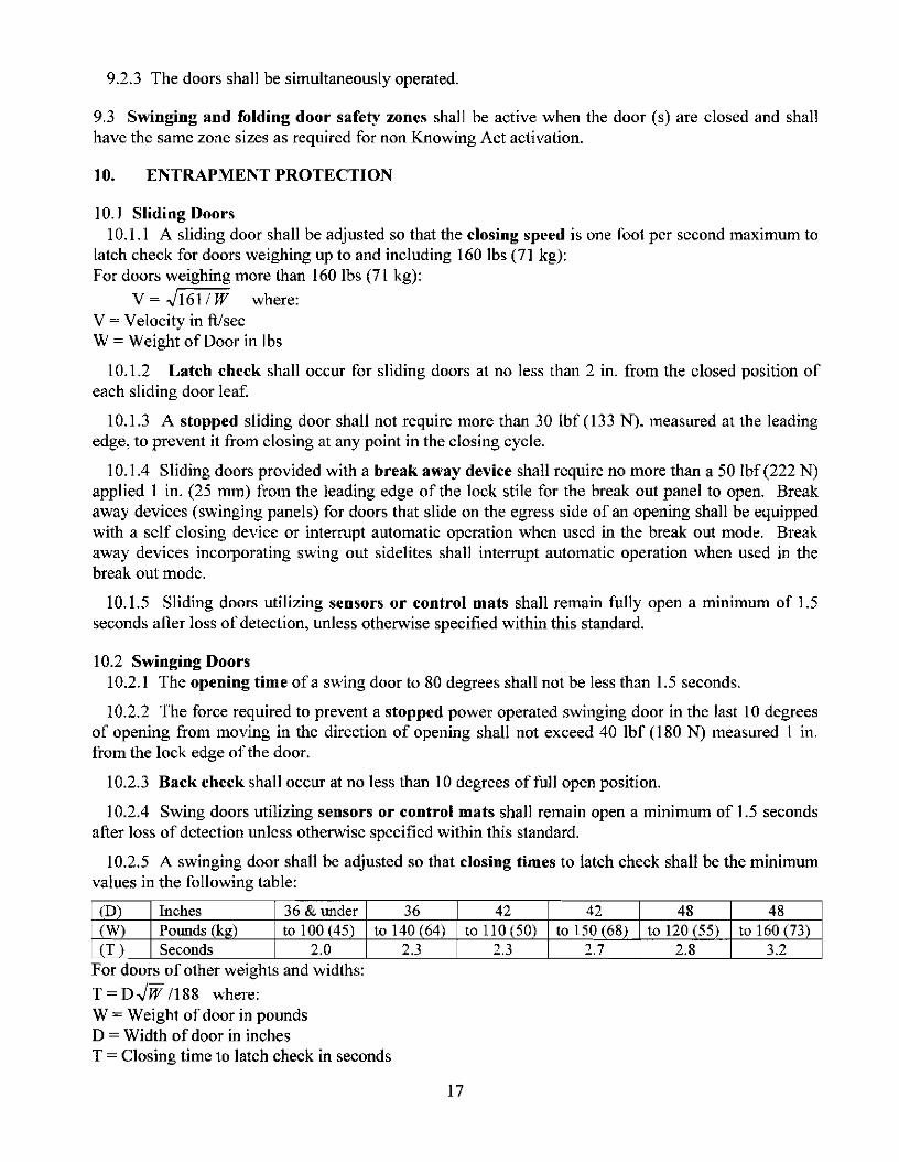
9.2.3 The doors shall be simultaneously operated.
9.3 Swinging and folding door safe!)' zones shall be active when the door (s) are closed and shallhave the same zone sizes as required for non Knowing Act activation.
10. ENTRAPMENT PROTECTION
10. I Sliding Doors10.1.1 A sliding door shall be adjusted so that the closing speed is one foot per second maximum to
latch check for doors weighing up to and including 160 lbs (71 kg):For doors weighing more than 160 lbs (71 kg):
V = .J161/ W where:V = Velocity in ft/secW = Weight of Door in lbs
10.1.2 Latch check shall occur for sliding doors at no less than 2 in. from the closed position ofeach sliding door leaf.
10.1.3 A stopped sliding door shall not require more than 30 Ibf (133 N), measured at the leadingedge, to prevent it from closing at any point in the closing cycle.
10.1.4 Sliding doors provided with a break away device shall require no more than a 50 Ibf (222 N)applied 1 in. (25 mm) lrom the leading edge of the lock stile for the break out panel to open. Breakaway devices (swinging panels) for doors that slide on the egress side of an opening shall be equippedwith a self closing device or interrupt automatic operation when used in the break out mode. Breakaway devices incorporating swing out sidelites shall interrupt automatic operation when used in thebreak out mode.
10.1.5 Sliding doors utilizing sensors or control mats shall remain fully open a minimum of 1.5seconds after loss of detection, unless otherwise specified within this standard.
10.2 Swinging Doors10.2.1 The opening time of a swing door to 80 degrees shall not be less than 1.5 seconds.
10.2.2 The force required to prevent a stopped power operated swinging door in the last 10 degreesof opening from moving in the direction of opening shall not exceed 40 lbf (180 N) measured 1 m.from the lock edge of the door.
10.2.3 Back check shall occur at no less than 10 degrees of full open position.
10.2.4 Swing doors utilizing sensors or control mats shall remain open a minimum of 1.5 secondsafter loss of detection unless otherwise specified within this standard.
10.2.5 A swinging door shall be adjusted so that closing times to latch check shall be the minimumvalues in the following table:
(0) Inches 36 & Ill1der 36 42 42 48 48(W) POlll1ds (kg) to 100 (45) to 140 (64) to 110 (50) to 150(68) to 120 (55) to 160(73)(T) Seconds 2.0 2.3 2.3 2.7 2.8 3.2
For doors of other weights and Widths:
T = D.JW /188 where:W = Weight of door in poundsD = Width of door in inchesT = Closing time to latch check in seconds
17

10.2.6 Latch check shall occur for swinging door at no less than 10 degrees from closed positionand the door shall not close through the final 10 degrees in less than 1.5 scconds.
10.2.7 The force required to prevent a stopped power operated swinging door from moving in thedirection of closing shall not exceed a 30 Ibf (133 N) measured 1 in. from the lock edge of the door atany point in the closing cycle.
10.2.8 In the event of power failure, a swing door shall be capable of being opened manually withno greater than a 30 Ibf(l33 N), applied 1 in. from the edge of the lock stile to open.
10.2.9 Swinging doors provided with a hreak away device shall require no more than 50 Ibf (222N) applied I in. from the edge of the lockstile to open. When the door(s) is opened in the break outmode, powered operating components excluding spring power shall not operate the doors.
10.2.10 The opening at hinge side of swinging doors shall be: a) Less than I;' in. wide with thedoor in any position, or b) At least ';' in. wide with the door in any position. A door that does notcomply with the above is acceptable if provided with a finger guard.
10.3 Folding Doors10.3.1 Opening time of a folding door to back check shall not be less than 1.5 seconds.
10.3.2 The force required to prevent a stopped power operated folding door in the last 10 degreesof the opening, from moving in the direction of opening shall not exceed 40 Ibf(l80 N) measured 1 in.from the leading edge ofthe FS leaf.
10.3.3 Folding doors utilizing sensors or control mats shall remain fully open a minimum of 1.5seconds after loss of detection unless otherwise specified within this standard.
10.3.4 A folding door shall be adjusted so that the closing speed to latch check is a maximum of 1foot/sec. (287 nun/sec.) measured at the leading edge.
10.3.5 Latch check shall occur for folding doors at no less than 2 in. from the closed positionmeasured per FX leaf.
10.3.6 A folding door shall not close through the last 2 in. in less than 1.5 seconds for each FX leaf.
10.3.7 A stopped folding door shall not require more than 30 Ibf (133 N). measured at the leadingedge of the FX panel, to prevent it from closing from fully opened to latch check.
10.3.8 Folding doors provided with a break away device shall require no more than 50 Ibf (222 N)applied 1 in. (25 mm) from the edge of the lockstile to open. When the door (s) is opened in the breakout mode, powered operating components excluding spring power shall not operate the doors.
10.3.9 The opening at hinge side of a center pivoted folding door shall be: a) Less than V. in. widewith the door in any position, or b) At least % in. wide with the door in any position. A door that doesnot comply with the above is acceptable ifprovided with a finger guard.
11. SIGNAGE Consistent with section 2.2.1 of ANSI Z535.4, the "signage and warnings"guidelines of A 156.1 0 are recognized, industry-specific standards that predate the adoption of Z535.4and are not replaced by the standards set forth therein.
18
11.1 All swinging, sliding and folding doors shall be equipped with signage visible from both sidesreading, "AUTOMATIC DOOR" with letters 1/2 in. high minimum. The sign described in Figures BI, B-3, B-5 shall be pennitted to be used to satisfY this requirement.
11.2 Swinging Doors (See Appendix Figures B-3 & 4)
11.2.1 An arrow sign shall be visible from the approach side of a swinging door mounted on thedoor at a height 58 in. ± 5 in. li'om the floor to the center line of the sign. The sign shall be a minimumof 6 in. in diameter, having a green circle surrounding a black arrow on a white background.
11.2.2 An international "DO NOT ENTER" sign shall be visible from the side of doors that swingstowards pedestrians attempting to travel in the wrong direction mounted on the door at a height 58 in.± 5 in. from the floor to the center line of the sign. The sign shall be a minimum of 6 in. in diameter,having a red circle with the wording, "DO NOT ENTER," in the red circle.
11.2.3 Swinging doors serving both egress and ingress shall be marked with a decal, visible from theswing side of the door, with the words "AUTOMATIC CAUTION DOOR." The sign shall bemounted on the door at a height 58 in. ± 5 in. ITom the floor to the center line of the sign. The signshall be a minimum of 6 in. in diameter and with black lettering on a yellow background.
11.3 Sliding Doors (See Appendix Figures B-1 & 2)
11.3.1 Sliding doors with swinging leaves shall be provided with signs reading, "IN EMERGENCYPUSH TO OPEN." The signs shall have red backgrounds with contrasting letters 1 in. high minimum.The signs shall read horizontally and be located adjacent to the lock stile on a center line 36 in.minimum and 60 in. maximum from the floor applied to the side appropriate for egress.
11.3.2 Sliding doors that slide alongside an adjacent sidelite or wall shall be equipped with a signthat instructs users to stand clear of the sliding door travel path. The letters shall be I in. highminimum on contrasting background and located at 36 to 60 inches from the floor.
11.4 Folding Doors (See Appendix Figures B-5 & 6)
11.4.1 For one way traffic folding doors. an arrow sign, shall be visible from the approach side of afolding door mounted on the door at a height 58 in. ± 5 in. from the floor to the center line of the signon the FX paneL The sign shall conform to the sign described in paragraph 11.2.1. On the nonapproach side the international "DO NOT ENTER" sign as described in paragraph 11.2.2 shall bevisible. If folding doors are being used in pairs, each FX panel is required to have signs.
11.4.2 Folding doors serving both egress and ingress shall be marked with an arrow sign asdescribed in paragraph 11.2.1, visible from the non fold side and the fold side shall be marked with the"AUTOMATIC CAUTION DOOR" sign as described in paragraph 11.2.3.
11.4.3 Folding doors shall be provided with signs as described in paragraph 11.3.1, mounted on theFX panel applied to the side appropriate for egress and a "DO NOT ENTER" sign as described inparagraph 11.2.2 shall be applied to the appropriate sides of the FX panel as determined by trafficflow.
11.5 Knowing Act Doors (See Appendix Figures B-1 & 3 & 5)
11.5.1 The door shall have signage which says "Automatic Door" along with other required signagevisible from each side of the door. In addition the door shall have signage which says "Activate Switchto Operate" on the side of the door having the Knowing Act switch. Each sign in Yz" high minimumletters.
12. BREAK AWAY EGRESS TEST FOR SWINGING, FOLDING AND SLIDING DOORS.
19

12.1 Cycle Test Doors with power operators shall be installed in a simulated wall and door framingassembly of sufficient strength to withstand all forces required by the tests. Installation shall be inaccordance with manufacturer's printed instructions. Maintenance and repair of other than break awayequipment is permitted to be performed during the testing cycles.
12.1.1 The test specimen shall be of the largest door size to be listed by the manufacturer.
12.1.2 Cycle for 300,000 cycles at a rate of 5 to 8 per minute.
12.1.3 Break away devices shall not be lubricated or adjusted during the test.
12.1.4 At every 50,000 cycles during the test, the doors shall undergo 1.000 break out cycles. At theconclusion of the test, break out forces shall not exceed those listed in 10.1.4, 10.2.9, and 10.3.8.
12.2 Salt Spray Test
12.2.1 A sample of the latclllng and hinge assembly of the break away device of a power operateddoor contained in an approximately 25 in. wide panel shall be subjected to a salt fog test in accordancewith ANSI/BHMA A156.18-2000 for Materials and Finishes for 168 hours.
12.2.2 Record the release force prior to conducting the test. This shall not exceed 50 1bf (222 N).12.2.3 At the conclusion of the exposure time, remove the sample and allow to dry for 24 hours
without cleaning.12.2.4 Then cycle the sample 10 times. The release force for the first cycle shall not exceed a 100
lbf (445 N). Release forces for the next nine cycles shall not exceed 50 1bf (222 N).
20

TABLE 1 SYMBOLS USED FOR POWER OPERATED SLIDING DOORS
TYPICAL DOOR TYPES
PERINETER MOUNT
o a X+-0 o a x x a ,
O-X The sliding panel shall be installed tothe inside or outside of the sidelight. Slidingpanel slides along sidelight.
so ,>
oa O-SX The swing-slide panel shall be
installed to the exterior of the fixedsidelight. The swing-slide panel(s) (SX)shall swing out 90 degrees from anyosition of slide movement.
SO-SX The swing out sidelite (SO) shallbe installed to the exterior of the swingslide panel (SX). Swing out sidelight(s) is(are) provided to allow the sliding panel toswin out from an oint of slide travel.O/SO-SX Swing pocket panel applied tooutside of the unit.
P-SX Mounting of the unit is to theSURFACE MOUNT surface of the wall. As the door opens, the
L-_C__p__t_w_x_"'-l_f_/__·_t_"._" p_J ,Iidi', pm,1 ,I;d" be'id, <h, w.IL
21

onve mc es 0 mm mUlplV
Door Opening Min. Width Activating Safety Mat Safety MatSize Required Side - Min. Min. Length Min. Lengthill. lU. Length 3 in. Threshold 1in. Threshold
ill. ill. ill.
36 26 43 36 Y. 37 Y.37 27 43 36 Y. 37 Y. CENTER42 32 43 42 Y. 43 Y. PIVOT43 33 43 42 Y. 43 Y. SINGLES44 34 43 44 Y. 45 Y.45 35 43 44 Y. 45 Y.48 38 43 48 Y. 49 Y.49 39 43 48 y. 49 Y.
48 38 43 24 Y. 25 y. CENTER50 40 43 24 Y. 25 Y. PIVOT60 50 43 30 Y. 3I Y. PAIRS62 52 43 30 Y. 31 Y.72 62 43 36 y. 37 y.74 64 43 36 Y. 37 Y.84 74 43 42 Y. 43 Y.86 76 43 42 Y. 43 Y.
36 26 43 41 Y. 41 Y. BUTTHINGE &
42 32 43 47 Y. 47 Y. OFFSET44 34 43 49 Y. 49 ',4 PIVOTS48 38 43 53 Y. 53 Y. (SINGLE)
48 38 43 29 Y. 29 Y. BUTTHINGE &
60 50 43 35 Y. 35 Y. OFFSET72 62 43 41 y. 41 Y. PIVOTS84 74 43 47 Y. 47 Y. (PAIRS)
TABLE I-A MINIMUM EXPOSED MAT SIZES FOR SWINGING DOORS (See 7.2)To crt· h t If 1 b 25 4
22

APPENDIX A (NOT PART OF A156.10)
APPENDIX A
FIGUREA·1 (Ref. 7.2.1,7.22 & 72.4)CONTROL MATLAYOUTS FORONE·WAYTRAFFIC BUTTOROFFSETPIVOTED SWIIIG DOORS.
S'(127mntM'\X.
THRffiHOo.D
DOOROP8IIING
AC~IATING
I/
5"(1271ml) 5' (127mrTilMAX M'\X.
DOOR OPENI NG
M IIIMJM REQUIREDE JPOSEOW [J"H S'(127mntMAX.
5' (127mntMI N. 5' (127mnjMI N.
~Sl~NG~L'""E"":D~OD"":R'""""::=::':J----- --l--lp""AlllllRUlJJollllllllFDUlJJollllollllR"=s=========:::1J---.-
(BUTT o ROFFSETPlVOTS) (BUTT o ROFFSlET PIVOTS)
FIGUREA·2 (Ref. 7.2.1,7.22,7.23,7.2.4& 6.1.1)CONTROL MATLAYOUTS FORTWD-WAYTRAFRC(IIIGRESSI EGRESS)BUTT OROFFSET PIVOTEDSWIIIG roORS.
GUIDE RAlLS
M'\XJM UM INACTIVE AREA3-314' (95mnj REF.FIGUREA-Q
SINGLEDODR(BUTT OROFFSlETPIVOTS)
23
12~

APPENDD< A (Continued)
FIGUREA-3 (Ref. 7.2.1,7.22 &72.4)CONTROL MATLAYOUTS FOR 0 NE-WAYTRAFFIC CENTERPIVOTED SWNG DOORS.
5' (121m1llMI\X.
THREBHa-O
DOOR OPINING
r'NMUM~WI~1I "
AGnIATING
SINGLEOODR(CENTER PIVOT)
//
5" (127mm) S'(127mrrtMAX MI\X.
DOOROPINING
AGnIATING
I/ \
/ \/ SAfElY \
/ "/ "
PAIROFOOORS(BlJTT 0 ROFFSET PIVOTS)
DOOR<PENING
5' (l27mIllMAX.
5' (127mIllMI N.
FIGUREA-4 (Ref. 6.1.1,7.2.3 & 72.4)CONTROL MATLAYOUTS FORTWo-WAYTRAFFIC (NG RESSI EGRESS)CENTERP1VOTEDSWNG DOORS.
THREBHa-O
SIMNGDOOR
SINGLEOODR(CENTER PIVOT)
24
MI\)(IMUMINACTIVE AREA3-314' (95mIII REF.FIGURE A- 9.
12-1

" (127mm)
43" (1092mm) MIN.ACTIVATIN REQUIRED (f)
EXPOSr LENGii'i
SI°"ccNC=G-'-LE=-=SL:-:-ID=-:E='DOOR
5" (127m
II PANICII BREAKAWAY
t43" (1092mm) MIN.
REQUIRED CM
~~~~~~~======:;~J:r LENG
I
APPENDIX A (Continued)
FIGURE A-5 (Ref. 7.3.1 and 7.3.2)CONTROL MAT LAYOUTS FORSINGLE SLIDE DOORS.
5" (127mm)
ACTIVATING
CLEAR OPENING~--- W1DTII ..
I---MINIMUM REQU'l',.fD~ II EXPOSED WID
II PANICII BREAKAWAY
5" (127mm
FIGURE A-6 (Ref. 7.3.1 and 7.3.2)CONTROL MAT LAYOUTS FORBIPARTING SLIDE DOORS.
BI-PARTING SLIDE DOOR
(1) SEE 7.3.3 FOR ONE-WAY TRAFFICEXPOSED LENGTH IS 24" MINIMUM 12-6-04
25

APPENDIX A (C01timsd)
CONTRa... MATSCROSS SECTIONS.
6" 152mm MAX. INACTIVE WIDTH
CROSS SECTION atTHRESHOIJ)
2-1/2" (64mm) MAX. NACTIVEAREA WHEN MATS ARE
PERPENDICUlAR 10OPENNG
FIGUREA-7(Ref. 7.5.3)
FIGUREA-8(Ref. 7.5.1)
PLAN VlEW- PERPENDICUlAR MATS
PLAN \/IEW- PARALLEL MATS
CROSS SECTION A-A at JONT
3-3/4" (95mm) MAX. NACTIVEAREA WHE N MATS AREPARALLEL TO OPENING
CROSS SECTION B-B at JONT
FIGUREA-9(Ref. 7.5.2)
EXPOSE D AREA
MIN. RAMP LENGTH ACllVE4 x MATTHICKNESS 1-1/2" (38mm)
I-II!-----......... MAX. ~~~-+-.INACTillE
CROSS SECTION atSURFACE MAT TRIM
26
1/2" (13mm) MAT1THICKNESS
FIGUREA-10(Ref. 7.1, 7.5.4, and 7.6.4)
11-1-04

APPENDIX A (Continued)
FIGURE A-11 (Ref. 6.1)GUIDE RAL LAYOUTS FORSV\IINGING DOORS
Q)6' (152mm) MAX.2' (51m m) MIN.
6" (152mm)MAX.
ACllVAllNG
II
I
bAPPROAQ;SIDE
6' (152mm)MAX.
APPROAQ;
ACllVAllNG
(1) SWING DOORIN HALLWAY UTlLlZlNGKNOVVING)('CT ACTIVATING DEVICEMAX 10"WlTHOUTADDING AGUIDE RAIL
SWINGDOOR
30" (762mm)MIN.
I
PANEL
1'::' (152mm) MAX.
WIDTH a= DooRMINIMUM
JAMB I FLOOR MOJNTED
SWING DOOR ---
GUIDERAL ELEVATDNS.
FREE STANDNGI FLOORMOJNTED
PLAN VIEW-ONE-WAYTRAFFIC DOUBLESWIt<G DOORS.
REFER TO FIGUREA-2 FOR GUIDE RAIL LAYOUT INlWO-WAYTRAFFIC(INGRESSI EGRESS)APPLICATON(REF. A-12Aand 6.1.1, EXCEPfON#2).
DOOR WIDTH a= DooR-MINIMUM
11-1-04
27

APPENDIX A (Continued)
FIGURE A-12A( Ref. 8.1 & 82)ACTIlfATtiGANDSAFETY DETECll0NZONES·SWIP«> DOORS.
B
REF. 8.22.2 FOR REQUIREMENT FOR ASAFEW BEAM OR PRESENCE DETECTIONON THE SAFEW ZONE SIDE OF lHE DOOR
30"(762mm)
30"(762mm)
TWO-WACfTRAFFIC
B
ACl1VAl1NG -+---.,...DElECTION ZONE
S'MAX.
A = M N IMUVI ACTIVATING DETECTION ZON E LEN GTH.B =MNIMUVI ACTIVATING DETECTION ZONE WIDTH.C = MINIMUM SAFEW DETECTION ZONE LENGTH.0= MINIMUM SAFEW DETECTION ZONE WIDTH.
A
C
T
30"762mm)
30"(762mm)
30"762mm)
ACl1VAliNG -J---r( DElECTION ZONE
5' (127mm)
..L..1-~~O~N~E~_W~I4;=Cf==:Y~-mrrrTRAFFIC 1--1 ~~~27mm)
MAX.
A
C
A
C
S' (127mm) .-........._..::D~_....--t S' (127mm)MAX. ONE-WACf MAX
TRAFFICNOTE: T HEDETEC110NZONEPAT1ERNS D ER C1EllINTHE AEDIC
~~~~~U~,§~o"r:::'~NOTTOSCAL.E)ANDFOR
11-1-04
28

APPENDIX A (C01timed)
APPENDIX A (C01timed)FIGUREA-12B(Ref. &2.2.3)ACllVATING ANDSAFErYDETECTION ZONES- SWING DOORS WITH DOOR MOUNTEDSENSORS.
B I
~-~-~// \',J \
MINIMUM ..------.ACllVAllNG
A DElECTIONI ZONE
I
SWING DOOR
OOORPWOT
GUIDE RAILS
A =MINIMUMACfIVATING DErECTIONZONE LENGTH.B =MINIMUMACfIVATING DErECTIONZONE WIDTH.C =SAFErY DETECTION ZONE DEPTH B~EDON PERFORI'v'I6.NCED =MINIMLM SAFErY DETECTION ZONE WIDTH.
NcrrE: 0 ElECTIClIIZDNES 0 ERCTEDI NTHE AIDRAIllANGSAREAP~DJlMA1E(NOTTO :rAUAND FORI LLUsrRAlIONP URFOlESONLY.
29

APPENDIX A (Cmtimed)
FIGUREA-12C (Ref. 8.23)ACTIVATING ANDSAFETYDETECTlQII.I ZQII.IES- SWING DOORS WITH DOOR MOUNTEDSENSORSTWO-WAY TRAFFIC.
B I
30"(762mm)
8"
r.:1 5" (127mm MAX.
A
~~..~,1l' ",I ,
, '..---.......MINIMUMACllVAllNG IDElECTION
ZONE
TC
SWING DOOR
DOOR PIVOT
~~I>' "::>~ ~
../
GUIDE RAILS
55" (1397mm)MINIMUM
I
L "I--.;;a_........'
B
TWO-WAYTRAFFIC
A = MINIMUMACTIVATING D ETECTION ZONE LENGTH.B = MINIMUMACTIVATING D ETECTION ZONE WIDTH.C = 55" MINIMUMACTIVATING DETECTION ZONE & GUIDE RAIL LENGTH.
SEE FIGUR:A-12B FOR SAFETY ZONEDIMEt-510t-5.
NOTE: 0 ElECTlOIIZCNES 0 ERCTElJI NTHE AlDIEDRAVIANGSAREA PFROllMAlE(NOTTO s;ALE)ANDFORlLLusrRAllONP URFOlESCNLY.
30

APPENDIX A (C01tim.ed)
FIGUREA-13 (Ref. 8.2)ACTIVATING DETECTIONZONES-SUDE DOORS
r~I SLIDING I \\~ SLIDING
PANEL PANEL
I \\I \ ~
\
A =MINIMUM ACTIVATING DETECTION ZONE LENGTH.B =MINIMUM ACTIVATING DETECTION ZONE WIDTH.
TWO-WAY TRAFFIC
cD REFER T08.3.3 FOR ONE-WAY TRAFFIC
5" (127mm) MAX.
-;[]5" (127mm) MAX.-- i----;
__ Cl
MINIMUMAC11VAllNG
DElECTION ZONE
A
\\ I
-~--'-'------"""'-- .-.r-L,----
cD A
FIXEDPANEL
B
NOTE: D ElECfICl'lZONES D ERCfEDl NTHE AID\EDRAIMNGSAREA PFROllMAlE(NOT TO s::ALE)AND FORI ll.usrRA1l0NPURFOlESONly. 11-1-{)4
31

APPENDIX A (Contilued)
FOUlNG DOORS PANEL LAYO UT
FigureA-14(Ref. 5.0)
SINGLE Fa.DlNG DOrn
FS
PAIR OF FOLDNGDOORS
FS= FOLDSWING PANEL
FX= FOLDSLIDEPANEL
FS
GUIDE RAL LAYOUTS FOR FOLDNG DOORS
FigureA-15(Ref. 6.2)
PAIR OF FOLDNGDOORS
''A"
M~
GL.ideRail
Z'Minimum6" Maximum
SINGLE Fa.D1NGDOrn
~III
"A"Mirirm.m
Z'MinimumG'Maximum
"A" =12 inch.,(305nm),forT'AO Wily
Traffic orOneWayTraffi:approadlilg from theFotJ Side.
or
5 inches,(130mm), for One Wily
Traffic a pproaching from theNon-Fold Side.
JAMB AND FLOOR MOUNlED FREE STANDNG FLOOR MOUNTED
11-1-04
32

APPE NDD< A (Continued)
CONTROL MAT LAYOUTS FOR FOLDING DOORS
FigureA-16
(Ref. 7.4 throug, 7.4.4.)
CONTROL MAT LAYOUT FOR ONE-WAY TRAFFIC FOLDING DOORS
Door Opelirg Door Opelirg- s,l-- -s' - - s' f- - s' I--
tMi Ii mum
Activatirg Req'd ActivatirgExposedLerg1h43"'I
-. -. .....
--
~ 1 ""-
~ ~....
Safely SafelyMilimLrnReq'd
Exposed
t 'T' J,S'Mi~mLrn Mi~mum
SINGLE FQ.DlNGDOCR PAIR OF FOLDING DOOR
CONTROL MAT LAYOUT FOR TWO-WAY TRAFFIC FOLDING DOCRS
DoorOpelirg DoorOpelirg
- S' I-- - s' - - s' f- - S' -f
Activatirg MilimLrn ActivatirgReq'd~osed
yo- ff ~f.y 1
~-
~I \~-
Milimum ff SafelyReq'd
Exposed
• Ler Js' S'
Mi~mum Mi1nun
1Activatirg 43"Min Activatirg
!
11-1-04
33
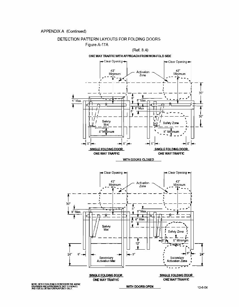
APPENDIX A (Continued)
DETECTION PATIERN LAYOUTS FOR FOLDING DOORSFigure A-17A
(Ref. 8.4)
----
ONE WAY TRAFFIC WITH APPROACH FROM NON-FOLD SIDE
[
Clear Openmg_ [Clear Openlflg_
4~ . . ~"
Minimum V A~~~:on~ Minimum1·- - .... _.-/ _-- - ... .- ......
~ ~-, ,---f----- ~------T-- --+-rl - - -T - - - - -. -.- - - - - -', - - - - I 30", B" t .. ,5" Max, rr-t:l:.,::---------:::-'-i---+t--T-,.. 5" Max. n ~ - - .. - "'-DI r • .J1 I
H--fl-+-I+-,-1 1-----1 I- .~ 5" Max, I I 1 I
~I /,'- - - - - 1- ~_.__
I III SafetyMat
----- I-
5" Mi~imum
SINGLE FOLDING DOORONE WAY TRAFFIC
SINGLE FOLDING DOORONE WAYTRAFFIC
WITH DOORS CLOSED
rC"~ O~;"g - rClear O~,ening •
4~ I Activation 4~Minimum V Zone ~ MInimumP#--"'_ .../· ,1'- -1IlIo_ ... ,
, ,,;;-... ""
r-----f-----~------r-----30" ---;--- _--1-.-- - - _~ __ - -_I
! 5~ • 8" t \ .T rT"""P[+:,l,;-W---::R:=---"'-_-H~--;-' , :" M1ClX. DI I-+'=-~~- -~
I- WSafety i 5~Max. ~ ~""''''-~-'''''LM. , I
U I Safety Zone ~
, 1... t- - - - - - - -a- - 1-.... - ~ - - .-
.,. ~ 6" 5" Minimj.lm
L .:,. -:-f--:. :. r5~' ~~I2r-:---I I-- - I-5" -..I r- 2<'
~I2::=A=ct=sr=V~=~=i~d=na=a=a=t=:SJ ~_~_"...'_:_~-:-~:-e:-:-~:-~-=-~.:.......e., ~~
SINGLE FOLDING DOORONE WAY TRAFFIC
SINGLE FOLDING DOORONE WAY TRAFFIC
NOlE: DElECTION ZONES DEPICTED IN THE ABOVEll'lAWlf«lS AIlE AI'PROlU MATE tN:JTTO !iCAlE)AND FOO.ILLUIITRATION PURPC6ES I;tllY.
WITH DOORS OPEN 12-6-04

APPENDIX A (Continued)
DETECTION PATTERN LAYOUTS FORFOLDING DOORSFigure A-17B
(Ref. 8.41
30'
J
raea~~~ingl raea~~~in91
Mi ri mum I I Mirimum I----/~,----=~~~~..~ ~~1;~~k'~ ~-_t~--=~----'-t--I• '5',' •• , Max. ~ ,
- - ---. - - - - - - - - -,,- - - -.-.-, - - - - - .. .:- - - - - - - -,-, - -- 30
.. -.. - - - - r ~' r I - - - - t--=-.-----------,"""J+ I
f-+-+Ill----+--,'----------------+l......J-4f--+-i 5"8'J, -j=J=±;:---+:~;-oii~---------~.-----;..---.;-;;;~~+-j,lI I I ... -----, ... -.-
II ! I \ \ II Maxi. - L _1.1;1 - - - - - - - - - -~\1l-
II~I / Safely Mat I
J\III M~'X.:{/ Sa~e1~Zo~ \~
I1 '1 ,
5"Mnimum l" -'" 5"Minimum.- , I, ~ - .. --~.-~ I
~~~ ~~ ~~~PAIR a= fULDlNG DOORS PAIR a= fULDlNG DOORS
ONE WAY TRAFFIC ONE WAY TRAFFIC
WITH DOORSCLOSED
]J
I30'
J
r a:~~in9 "II r aea~~~ing IM~'.mum Miri mum I
_- .. _.... ~ActivatiOO~., __ - po-- _
_ _ eI-::'- _ _ _.:~~ __ -.!ooe ~-:... ~""""~.__
• '5'" •t , Max. ~ ,
-~- ~ - -.::- ~.=-.-:. - -.- -,-1-+1- - - --';-.-:':.:.:-.-:: =-.-,~ - ~
"ir~_~~~~~~~J\' l~i.~ ~ r{~~;i~~~ =5" Minimum 'r ~_ 5" Minimum ':iTr + 12",.- - ..-:.~ ": - -
~, ,~ k-
• aear Door Opering ,24" 5" 5" ._ : Less 10' •
C Secaldary ~ •Activatioo Mat .... SecallBy ,
.. _.. Activali00 Zore.- .- .-l!:::===========::-..J - • - - _ .. '-
PAIR a= FOLDING DOORS
ONE WAY TRAFFIC
PAIR a= fULDlNG DOORS
ONE WAY TRAFFIC
WITH DOORSOPEN
NOTE: DE1ECTIOIIZCNES DERCTEO NTHEAB:l1EDRAVIANGSAREA PFROXMA1E(NOT TO s:ALE)ANDFORJ U.UsrRA~ONPURR:>G;SCNLY 12-8-04
35


APPENDIX A (Continued)
{Rlf!<f.3.4)
ONE WAY TRAFFIC WITH APPROACH FROM FOLD SliDE
DETECTION PATIERN LAYOUTS FOR. FOLDING DOORS
Figure A.170
.
5"Mm.,
SINGLE FOLDING DOOR PAIR OF FOLDING DOORSONE WAYTRAFFfC ONE WAY TRAFFIC
lQ::~t:rgk~::;~~~~c,ea~~£::g:1
' , or - .. ~:~=~) .. _.. _.. .... ~.. _....-- t -I-- , -- --.' -- - 1 --
I ,5' I ,\0 ,Max. I ,-- ---;. - -- ..-- ---. E -- --\-- -- - f-- -- --~- --
.. .... - ~ S" ... ... - .. ...,. - - - • .,...
,,• Activaten• li:oe~ .. ....- ----
- ... ,,----
J. ---W,/~ ---:;:-,-... -H1""T, r ... ~:~.... ___ 't,,\,\:~i 1.'1/ J .. r-s.. """""'t I ~ 1/ - -- '11.....*_-+-I~I Safety Zone t, ~._ Max ~ I S~ Zone _ _ \.lL
.. ... 7 .. "I ....... ~·~I~I~~m.._·1 i I .. - .. _ !!i' Ml mum _ ... _... I
,.. ,. ::.r~ S' r foo' 5"\- t" *' ... .......... -- - - .. ..... -i S' •
, -- -- n 30' " --.- -- -- -- -- --;- -I 48~ Activation, IMinimurn
--4 .. ~:7_-_-_-__-1:__1===_-_-_-WITH DOORS CLOSED
SINGLE FOLDfNG DOOR PAIR OF FOlDING DOORSONE WAY TRAFFIC ONE WAY TRAFFIC
lQ:i~~krgc:=~~agn~c'ear:~~:n: :1
- - (ktFile \!riIh .. -.. .., ... - DocrOpenj ...... - ..........
t - ,--------." --- -- 1
I 5"'5" .. ' •Max. ,Malt I •* ~ --- -- -. r --~..~ ...-'-.........----- ~ , 8" ..... ..... -
,•
.. f.-- --
.--- ... ---- ..... '\11,L..- - - - tl\ \JI:__ SafelyZone __ • \U
.::;==I--+=="'II";::,==+::....;.~=--==:.,-=
'.. S" Mimmum I5"~ .._- ....._'-_..",: ::..15"... ~ ~ ..
t.-,• Activaten• li:oe~ .....~ -- --..... _... _-
..,-,- -- -- 31l" 48"
I~ Activation, IMinimum
---I, .. ~:--=-" -- -l: i===__
3fJ'
WfTH DOORS OPEN
12-6-04
37

APPENDIX A (Contilued)
A-18A (Ref. 8.3.2.1) VERllCAL SECTIC»I· SLDEDOOR SHOW~ ACTIVATNG DETECTION ANDPHOTOELECTRIC BEAM ZC»I ES (4 mirirmm).
ACllVAllNGDElECTION ZONE - 2.5SECONDMN. TIMEDELAY
SLDING
DOORPANE~
I
/;/o
B
3" (16m m) MAX. FROMCENTERUNE OFSLDING PANEL
TOP PHOTOELECTRIC BEAMLOCATED BElWEEN55" (1397mm) AND45" (1143mm)
OTHER BEAMS LOCATEDNOT GREATER THAN6' (152) -12" (305mm) APART
BOTTOM PHOTOELECTRICBEAM LOCATED BETWEEN28" (711mm) AND 6' (152mm)
A =MAXIMUIII DISTANCE 10 ACTWAllNGDETECllON ZONEB =43" MINIMUIII
A-18B (Ref. 8.3.2.2) VERTICAL SECTION - SUDE DOOR SHOWNG ACTIIIATING AN 0PRESENCE oElECTION ZONE lHROUGl DOOR OPENNG.
ACllVAllNGDElECTION ZONE 1.5SECONDMN. TIMEDELAY
PRESENCEDElECTION ZONE
SLDINGDOOR PANEL
NOTE: 0 ElECTIOIIZONES 0 ERCTEDI NTHE AEDIEDRAWNGS ARE A PFROJIMA1E(NOT TO s::ALE)AND FORI LLusrRA]ONP LJRR:)!ESCNLY.
C
PHOlOELECTRIC BEAMSAS SHO\I\INARE REQUIRED IF PRESENCEDElECTION ZONE IS DEACTIVATED WHENDOOR STARTS TO CLOSE.
TOP PHOTOELECTRIC
~BEAM LOCATEDBETWEEN
I 55" (1397mm) AND,ri.If--.C<-".¥'It4H70'-+------·/ 45" (1143mm)
BOTTOMPHOlOELECTRICBEAM LOCATEDBETWEEN
1--1T',"'TSQHHH'-h'7f'--.J 28" (711mm) AND6' (152mm)
A = MAXIMUIII D ISTANCE 10 ACTWA11NG DETECllON ZON EB =MNIMUIII PRESENCE DETECTION ZONE WDTH (SEE 8.3.2.2)C = 43" MINIMUIII
12-6-04
38
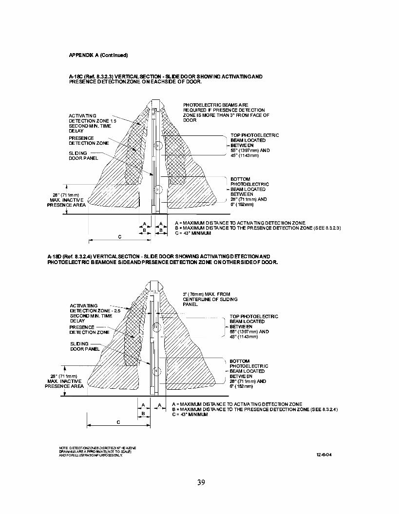
APPENDIX A (Continued)
A-1lC (Ref. 8.32.3) VERTlCALSECTlON· SLDE DOOR SHOWIPG ACTlVATlNGANDPRESENCE DETECTIONZONE ON EACHSDE OF DOOR.
ACllVAllNGDElECTION ZONE 1.5SECONDMN. TIMEDELAY
PRESENCEDElECTION ZONE
SLDINGDOOR PANEL
C
PHOlOELECTRIC BEAMS AREREQUIRED F PRESENCE DElECTIONZONE IS MORE THAN 3" FROM FACE OFDOOR
TOP PHOTOELECTRICBEAM LOCATEDBETWEEN55" (1397mm) AND45" (1143mm)
BOTTOMPHOlOELECTRICBEAM LOCATEDBETWEEN28" (711mm)AND6" (152mm)
A = MAXIMllv'I DISTANCE 10 ACTWAllNG DETECll0N ZONEB = MAXIMllv'I DISTANCE 10 THE PRESENCE DETECTION ZONE (SEE 8.3.2.3)C= 43"MINIMllv'I
A-llD (Ref. 8.32.4) VERTlCALSECTlON· SLDE DOOR SHOWIPG ACTIVATING D ETECTION ANDPHOTOELECTRIC BEAMONE SIDEANDPRESENCE DETECTION ZONE ONOTHERSIDEOF DOOR.
ACllVAllNG =~-;::;--.,F;.«f;)DElECTION ZONE - 2.5SECONDMN. TIMEDELAY
PRESENCEDElECTION ZONE
SLDINGDOOR PANEL
C
NOTE: D ElECTIOIIZCNES DERCTECl NTHE AlDIEDRAINNGS ARE A PFROl4MAlE(NOTTO s::Al.E)ANDFORILLusrRAlIONP URFO:'ESONLy.
3' (76mm) MAX. FROMCENTERUNE OF SUDNGPANEL
TOP PHOTOELECTRICBEAM LOCATEDBETWEEN55" (1397mm) AND45" (1143mm)
BOTTOMPHOlOELECTRICBEAM LOCATEDBETWEEN28" (711mm) AND6" (152mm)
A = MAXIMllv'I DISTANCE 10 ACTWAllNG DETECll0N ZONEB = MAXIMllv'I DISTANCE 10 THE PRESENCE DETECTION ZONE (SEE 8.3.2.4)C = 43" MINIMllv'I
12-6-04
39

APPENDIX A (Continued)
FIGURE A-19A(Ref. 9.2)'Knowing Act' - Double Egress (Using Header Mounted Sensors)
Push Plate SVlAtchActivation:After push plate is pressed &released door to remain open amirimum offive seconds.Switch to be installed withinview of door at a maximumdistance of 144" (3658mm) fromthe cerier of door and mounteda minimLlTl of 36" (914mm) andmaximLlTl 48" (1219mm) fromthe finished floor.
Clear DoorOpenng
FIGURE A-19B (Ref.9.2)'Knowing Ad'- DoubleEgr.s (Using Door MountedSafelySensors)
(i)SWlNG D OORIN HALLWAY UTIUZING ~~~~~i=~~!if'=~le=~~~~~~~~i;J;;T8" (203)~OWINGACTACTfliATINGDEVICEMAX.E Max.10" WITHOUT ADDING A GUIDE RAIL Inactive
see A12Bfor more details4-27-05
NOTE· DETECTION ZONES 0 S'ICTEDI N"THE AIPVEDRAWINGS AFE AFPROXIMATE (NOTTOSCALEjAt>{) FOR I LLUSTRATlONPURR:>SESONLY
40
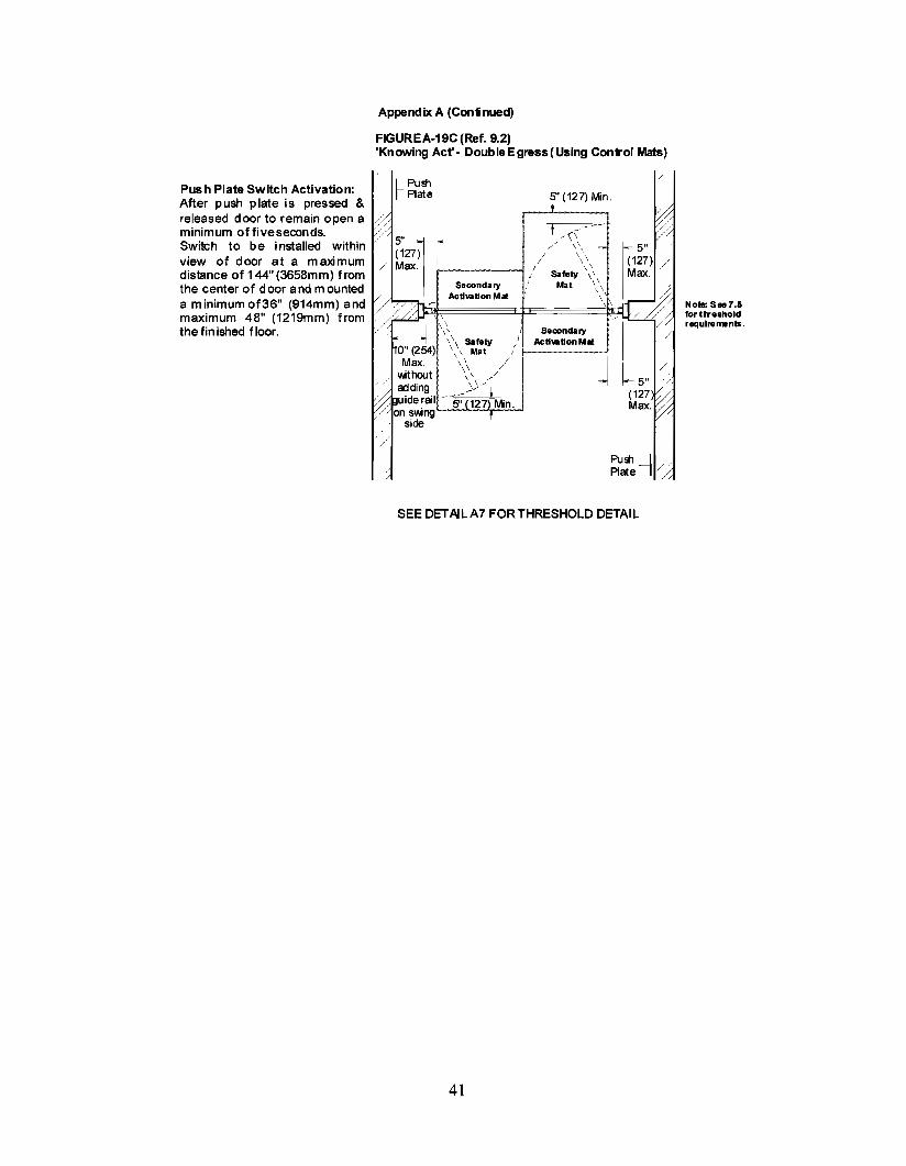
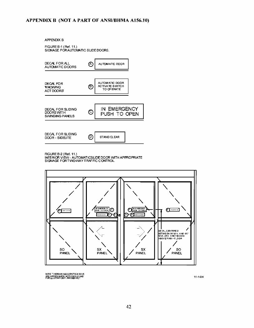
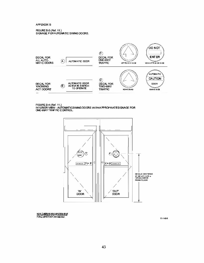
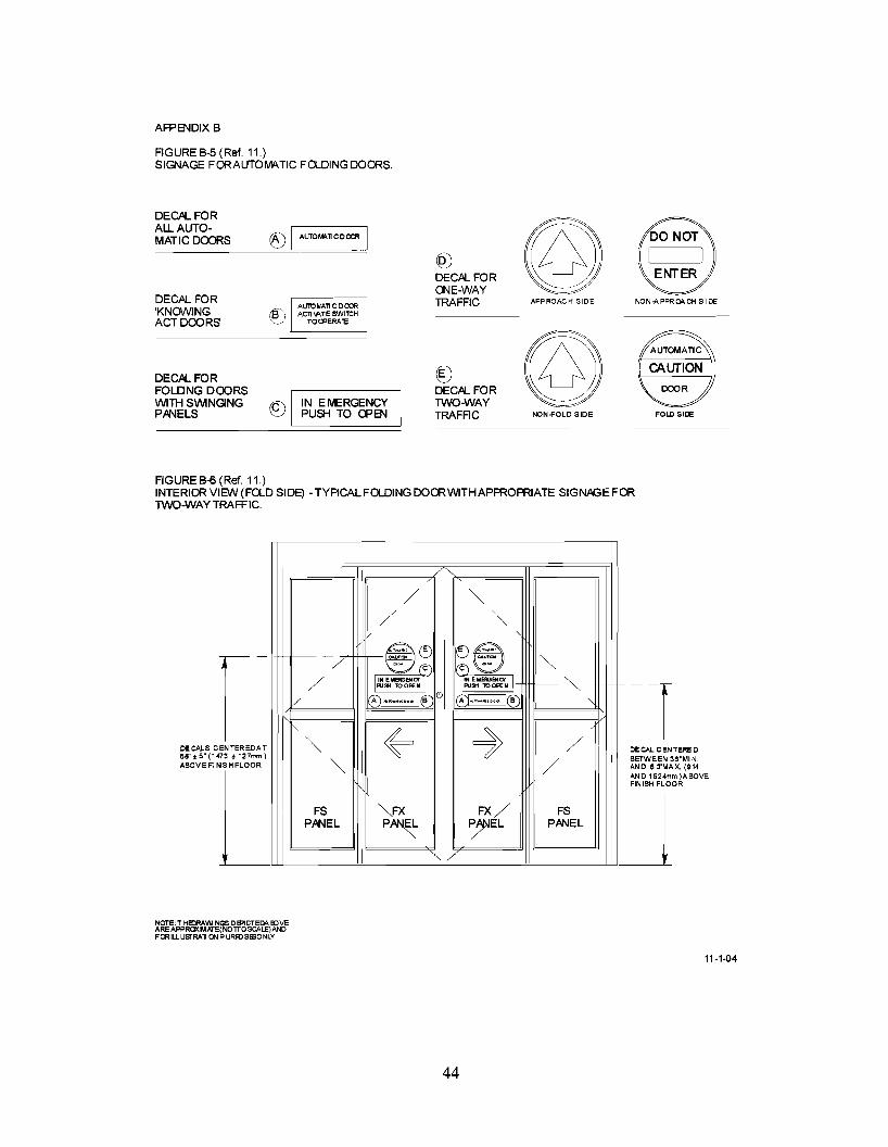
AFPB\lDIX B
FIGUREB-5(Ref,11,)SIGNAGE FORAUTOMA.TIC FO-DINGDOORS,
DECAL FOR
©AU. AUTO-
f) I AUTOM'>l1 C o OCR IMATICDOORS
@DECAL FORONE-WAY
DECAL FOR TRAFFIC APPROACH SlOE NON-APPRQl\CH SlOE
'KNOWING ®ACT DOORS
©DECAL FOR ©FOLDNG DOORS DECAL FORWITH SWINGING 8 IN EMERGENCY TWO-WAYPPNELS PUSH TO CPB\l TRAFAC NON.f'OLO SlOE FOLD SlOE
FIGUREB-$(Ref,11,)INTERIOR VIEW (FOLD SIDE) - TYPICAL FOLDING DOOR WITH APPROPRIATE SIGNAGE FORTWO-WAY TRAFFIC,
DE CAL C EN TERE 0BETWEEN 36"MIN,ANO 6 a'MAX, (914ANO 1524mm)ABOVEFIN ISH FLOOR
J
/ ""/ ""v
~~ ~~r-- - """''" ""...0 (CJ (CJ ...
/ IIIN EMBGENCY T 1:N EMElGENct~PUSH 100PEN PUSH TOOPEN
V- A ] .~••<OO. 1(B A ].~••<oo. I(B "" ~ ~
/
ENTEREOAT "" /73:: 127mm)
"" /SHFLOOR
I FS ""FX FX/ FSPPNEL P~ ~EL PPNEL
,,1/
DECALS C58'.5"(14ABOVEFltII
NOTE: T HEORAI/II NGS 0 El'ICTEOA IDVEAREAPPROXIMIQ"E(NOTTOSCALE)ANOFOR IIJ.USI"RAlI ON PURR:>SIEONLY
11-1-04
44


These should be countered by additional caution signage or sensors, restricting traffic, or reducing thedoor speed in both opening and closing. Activating zone, opening and closing force, speed, and safetyzone requirements should be considered.
49

ANSIIBHMA A156.10-2011Revision of ANSIIBHMA A156.10-2005
STANDARD
FOR
POWER OPERATED PEDESTRIAN DOORS
SPONSOR
••••BHMAbuilders hardware manufacturers
asscx:iation
BUILDERS HARDWARE MANUFACTURERS ASSOCIATION, INC.
American National Standards InstituteApproved August 2, 2011

AMERICAN NATIONAL STANDARD
An American National Standard implies a consensus of those substantially concerned with its scope andprovisions. An American National Standard is intended as a guide to aid the manufacturer, the consumerand the general public. The existence of an American National Standard does not in any respect precludeanyone, whether he has approved the standard or not, from manufacturing, marketing, purchasing, or usingproducts, processes, or procedures not conforming to this standard. American National Standards aresubject to periodic review and users are cautioned to obtain the latest editions.
CAUTION NOTICE: This American National Standard is permitted to be revised or withdrawn at anytime. The procedures of the American National Standards Institute require that action be taken to reaffirm,revise, or withdraw this standard no later than five years from the date of publication. Purchasers ofAmerican National Standards receive current information on all standards by calling or writing theAmerican National Standards Institute.
Published byBUILDERS HARDWARE MANUFACTURERS ASSOCIATION, INC.
355 Lexington Avenue New York, New York 10017
Copyright © 2011 by theBuilders Hardware Manufacturers Association, Inc.
www.buildershardware.com
Not to be reproduced without specific authorization from BHMA
Printed in the USA
This Standard was approved by ANSI under the Canvass Method. BHMA was accredited on 21 March1983 by ANSI as a sponsor using the Canvass Method.
2

FOREWORD(This Foreword is not a part of ANSIIBHMA A156.10)
The general classification of builders hardware includes a wide variety of items which are divided intoseveral categories. To recognize this diversity, a sectional classification system has been established.Power Operated Doors is one such section and this Standard is a result of the collective efforts of membersof the Builders Hardware Manufacturers Association, Inc. who manufacture this product. The total ProductStandards effort is, therefore, a collection of sections, each covering a specific category of items.
Performance tests and, where necessary, dimensional requirements have been established to ensurea degree of safety. There are no restrictions on design except for those dimensional requirements imposedfor reasons of safety.
This Standard is not intended to obstruct but rather to encourage the development of improvedproducts, methods and materials. The BHMA recognizes that errors will be found, items will becomeobsolete, and new products, methods and materials will be developed. With this in mind, the Associationplans to update, correct and revise these Standards on a regular basis. It shall also be the responsibility ofmanufacturers to request such appropriate revisions.
3

TABLE OF CONTENTS
1. GENERAL 5
2. DEFINITIONS OF TERMS USED IN THIS STANDARD.....................................................•..••.....................•..........6
3. SWINGING DOORS 8
4. SLIDING DOORS 8
5. FOLDING DOORS 8
6. GUIDE RAILS 9
7. CONTROL MATS REQUIREMENTS 10
8. SENSORS............................................•••••...•••.........••.••••••••..••...•...............•....................................•................••.•.••.........12
9. KNOWING ACT DOOR ACTIVATION 16
10. ENTRAPMENT PROTECTION 18
11. SIGNAGE........................................•.......••••..•..............••.•.••..•..............................•..................••••••.................................19
12 BREAK AWAY EGRESS TEST FOR SWINGING, FOLDING AND SLIDING DOORS 20
APPENDIX A 24
APPENDIX B................••••.••••••.••.................................................•••.•••...............•.•.•...............................•••..................•............46
APPENDIX C 49
APPENDIX D 52
APPENDIX E ••...•.............•............................•.....•.....•.........••••••••••................................................•..•.•.•..•................................52
4

1. GENERAL
1.1 Scope Requirements in this Standard apply to power operated doors for pedestrian use whichopen automatically when approached by pedestrians and some small vehicular traffic or by a knowingact. Included are provisions to reduce the chance of user injury or entrapment. Power operated doorsfor industrial or trained traffic are not covered in this Standard.
1.1.1 Where this Standard contains specifications relating to minimum or maximum dimensions ofvarious components of power operated doors for pedestrian use and some small vehicular traffic, suchdimensions are included to provide user protection for what are, in the industry, standard applicationconditions. This Standard does not apply to custom installations.
1.2 This Standard does not apply to power assist and low energy power operated doors. Refer toANSI/BHMA A156.19 for Power Assist and Low Energy Power Operated Doors.
1.3 Required dimensions are expressed in US units first; approximate metric equivalents follow inparentheses. The following is a conversion chart for inches to approximate mm equivalents where notgiven in the standard.
TO CONVERT INCHES TO MILLIMETERS, MULTIPLY INCHES BY 25.4TO CONVERT MILLIMETERS TO INCHES, MULTIPLY MILLIMETERS BY 0.03937.
Inches mm Inches mm Inches mm Inches Mm
1/16 1.6 6 152 23 584 45 11431/4 6.35 7 178 24 610 47 11941/2 12.7 8 203 25 635 48 12193/4 19 9 229 26 660 49 1245
1 25.4 10 254 27 686 50 127011/2 38 11 279 28 711 51 129513/4 45 12 304 30 762 52 132111/2 38 13 330 31 787 53 1346
2 51 14 356 32 813 54 13722.26 57 15 381 33 838 55 1397
21/2 63 16 406 34 864 56 14223 76 17 432 36 914 57 1448
3 3/4 95 20 508 40 1016 58 14734 102 21 533 41 1041 60 15245 127 22 559 43 1092 144 3658
1.4 American National Standards referenced in A156.1O are available from BHMA,www.buildershardware.com or the American National Standards Institute, www.ansi.org..
1.5 Tolerances Where only minus tolerances are given, the dimensions are permitted to beexceeded at the option of the manufacturers. All values which do not carry specific tolerances or arenot marked maximum or minimum shall have the following tolerances: Linear dimensions shall be ±1/16 in (1.6 mm). Pounds or pound force shall be ± 2%. Degrees opening shall be ± 2 degrees.Electrical measurements shall be ± 2%.
1.6 Tests described in this standard are performed under laboratory conditions. Measurements shall
5
be taken under neutral air pressure conditions. In actual usage, results vary because of installation,maintenance and environmental conditions.
1.7 Doors used as fire doors or smoke barriers have additional requirements not covered in thisstandard.
1.8 Where required by the authority having jurisdiction, products meeting the requirements of thisStandard are required to comply with UL 325-Fifth Edition June 2002, and be listed or labeled by anationally recognized independent testing laboratory and be under a periodic examination service.
1.9 Tests described in paragraphs 7.6 and 12 shall be performed under the supervision of a nationallyrecognized independent testing laboratory on preproduction samples prior to acceptance of the designfor production and subsequent installation. Production units shall be under an in-plant follow-upinspection service.
2. DEFINITIONS OF TERMS USED IN THIS STANDARD
2.1 Active Area The area where a sensor or control mat detects presence or motion.2.2 Activating Zone An area created by a sensor or control mat such that the door will open whenthe area is entered by (a) person(s) .2.3 Activating Zone, Secondary An area created by a sensor or control mat such that the door willreactivate or reverse and remain active until the door is almost closed.2.4 Automatic Door Operator A power operated mechanism that is attached to a door for thepurpose of mechanically opening and closing a door upon the receipt of an activating signal.2,5 Back Check The checking or slowing down of the speed of door opening before being fullyopened. (Also called Open Check.)2.6 Balanced Door A door equipped with a hinge which moves the hinge pivot point from the hingestile of the door towards the centerline of the door.2.7 Break Away Device A safety device other than an exit device that permits egress underemergency conditions. (Also called Emergency Release.).2.8 Break Out The process of activating a break away device causing the door or panel to swing inthe direction of egress.2.9 Center Pivoted A door which has the pivot point of the hinge located on the centerline of thedoor thickness.2.10 Clear Opening for Automatic Doors The following is for the purpose of sizing activating andsafety zones. Refer to applicable building codes for means of egress clear width requirements.
Swing Doors - With the door open 90 degrees, the clear opening is measured between the face ofthe door and jamb or jamb stop.
Pair of Swing Doors - With the doors open 90 degrees the clear opening is measured between thefaces of the two open doors.
Sliding or Folding Doors - In the fully opened position, the clear opening is measured from theedge of the leading stile to the jamb or jamb stop if present.
Pair of Sliding or Folding Doors - In the fully opened position, the clear opening is measuredbetween the edges of the leading stiles of the two doors.2.11 Closing Cycle Movement of a swinging, folding or sliding door from the fully open position tothe fully closed position.2.12 Closing Time Time from starting of a door closing until it is at rest fully closed.2.13 Control A unit containing electrical components for automatic control of door operation andoverload protection.
6

2.14 Control Mat An activating or safety device placed on the floor on either side of a doorwaysensing the presence of a person. It is constructed of a rubber like material with slip resistant surfaceand is either recessed into or surface mounted on the floor.2.15 Control Mat, Activating A control mat which when activated causes a door to open.2.16 Control Mat, Safety A control mat which when activated prevents a door from opening or holdsa door open.2.17 Custom Installations Where an installation condition exists such that all of the performancecriteria of this standard cannot be met.2.18 Cycle The action of an automatic door operator starting with activating through opening and fullclosing of (a) door(s).2.19 Door Opening for Automatic Doors The following is for the purpose of sizing activating andsafety zones. Refer to applicable building codes for means of egress clear width requirements.
Swing or Folding Doors (Singles or Pairs) The smallest width dimension of a door opening,measured jamb to jamb.
Sliding Doors Same as clear opening.2.20 Double Egress Swing Doors A pair of doors with no mullion that swing in opposite directions2.21 Face of Door The plane of the highest part of the door exposed to view when the door is closed.Does not include hardware or other applied products.2.22 Exposed Area The visible area of a control mat after the trim is installed.2.23 Finger Guard A device applied at the hinge stile of a door or to the hinge jamb adjacent to thedoor preventing damage to hands or fingers.2.24 Folding Door A pivoted swing panel hinged to a passive panel, the other end of which iscaptured in a guide, thus allowing it to slide as both panels swing into a V shape (the fold).2.25 Guide Rail A separator used with power operated doors for traffic separation and control.2.26 Inactive Area The area where a sensor or control mat does not detect presence or motion.2.27 Knowing Act With reference to the act of operating a door operator, such as pressing a switch withthe knowledge of what will happen.2.28 Latch Check The checking or slowing down of the speed of closing a door before being fullyclosed. (Also called Close Check.)2.29 Offset Hung A door which has a hinge pivot point located off the centerline of the doorthickness.2.30 Motion Sensor A sensor designed to detect the movement of a person in the vicinity of thedoorway and give a control signal to the power operated door.2.31 Power Operated Door The combination of door, operator and controls constituting the system.(Also called Automatic Door.)2.32 Presence Sensor A sensor designed to detect the presence of a stationary person in the vicinityof the doorway and give a control signal to the power operated door.2.33 Safety Zone An area of detection provided by presence sensors or control mats on swinging orfolding doors.2.34 Small Vehicular Carts used to transport people or objects.2.35 Telescoping Sliding Doors A type of sliding door with two or more leaves that slide in the samedirection, and arrive at the full open position at the same time.2.36 Threshold A floor mounted horizontal member installed beneath a closed door or in a clear dooropening.2.37 Trained Traffic People trained in the safe use and operation of a particular automatic doorinstallation.2.38 Trim, Mat Material installed around the perimeter of a control mat securing it to the floor.
7
Section 6Section 7 or 8Section 9Section 10Section 11
Section 6Section 7 or 8Section 9Section 10Section 11
3. SWINGING DOORS
3.1 Automatic swing door systems have a variety of configurations, including:• a single door swinging in or out, left-handed or right-handed• a pair of doors simultaneously swinging in the same direction• a pair of doors simultaneously swinging in opposite directions (double egress)
3.2 The door operator is concealed or surface applied. The doors are center pivoted, offset hung,balanced or hinged. No matter what the configuration or system, automatic swinging doors shallinclude guide rails, sensors or control mats, and signage for the safety and convenience of the useraccording to the following:
Guide RailsControl Mats or SensorsKnowing Act (when applicable)EntrapmentSignage
4. SLIDING DOORS
4.1 Automatic sliding doors are flat panels that slide horizontally and linearly. These systems havesuch a variety of configurations that symbols have been assigned to the individual panels that make upan entryway. See Table 1 for definitions of 0, SO, X, SX and P panels.
4.2 No matter what the configuration or system, automatic sliding doors shall include sensors orcontrol mats, and signage for the safety and convenience of the user according to the following:
Control Mats or Sensors Section 7 or 8Knowing Act (when applicable) Section 9Entrapment Section 10Signage Section 11
5. FOLDING DOORS
5.1 Automatic folding doors are comprised of two or more separate panels, of which one panel swings,and the other panel slides in a guide. Because of the number of leaves involved, see Figure A-14 fordefinitions of FX and FS panels.
5.2 Automatic folding doors include a variety of configurations, including:• a single folding door folding in or out, left hand or right hand• a pair of doors simultaneously folding in or out, left hand and right hand
5.3 No matter what the configuration or system, automatic folding doors shall include guide rails,sensors or control mats, and signage for the safety and convenience of the user according to thefollowing:
Guide RailsControl Mats or SensorsKnowing Act (when applicable)EntrapmentSignage
8

6. GUIDE RAILS
6.1 Guide Rails for Swing Doors (See Figures A-I, A-2, A-3, A-4, A-II, AI2-A,B,C, AI9-A,B,C)
6.1.1 Two guide rails shall be installed on the swing side of each door. Single doors shall have oneon each side of the door and pairs or double egress shall have one rail on each hinge side. Rails shallproject at least to the leading edge of the widest door in the fully open position.Exception #1: A wall or separator is permitted to be used in place of a rail, provided that it meets thecriteria in 6.1.2 through 6.1.5Exception #2: Guide rails for swinging doors serving both egress and ingress shall project out fromthe face of the door jambs on the swing side to no less than the outside leading edge of the open doorplus 55 in. (See Figures A-2, A-4 &A-12A,C.)Exception #3 If double egress doors or a pair of doors are installed in a hallway, no guide rails arerequired if the distance between the wall and the door in the 90 degree open position does not exceed10 in. (A-19 A,B,C)Exception #4 Guide rails for Knowing Act swinging doors serving both egress and ingress shallproject out from the face of the door jambs on the swing side to no less than the outside leading edge ofthe open door plus 12 in.
6.1.2 A guide rail shall be 30 in. high minimum measured from the finished floor surface.
6.1.3 A guide rail shall have a panel or a divider to inhibit access to the protected area.
6.1.4 There shall be 6 in. maximum clearance between the rail and the door in the fully openposition or between the rail and the leading edge of the door at the point in its arc of travel when it isclosest to the rail. There shall be a 2 in. minimum clearance between the rail at the hinge side and thedoor in the fully open position.
6.1.5 Free standing guide rails shall have a maximum dimension between the rail and jamb (orother adjacent surface) of 6 in.
6.2 Guide Rails for Folding Doors (See Figures A-14, A-15, A-16, A-17-A,B,C,D)
6.2.1 Two guide rails shall be installed on the fold side of the door. Single doors shall have one oneach side of the door; pairs shall have one rail on each hinge side and shall project beyond the foldopen position not less than 12 in.Exception: A wall separator is permitted to be used in place of a rail, provided that it meets thecriteria in 6.1.2 through 6.1.5.
6.2.2 Guide rails shall comply with 6.1.2 through 6.1.5.
9

7. CONTROL MATS REQUIREMENTS
7.1 General Requirements for Mats
7.1.1 The edge of the exposed area of all control mats shall not exceed 1/2 in. thickness. (See FigureA-10.)
7.2 Swinging Doors (See Table I-A)
7.2.1 The width of the exposed area of an activating or safety control mat shall be the width of thedoor opening less a maximum of 5 in. measured from both sides for a total maximum of 10 in. (SeeFigures A-I, A-2, A-3, A-4, A-12A.)
7.2.2 A safety zone shall be provided by a safety control mat on the swing side of the door. Thelength of the exposed area shall extend a minimum of 5 in. beyond the lead edge of the door in the openposition. (See Figures A-I, A-2, A-3, A-4, A-12A.)
7.2.3 Swinging doors serving both egress and ingress, including non-knowing act double egressdoors, shall have a series of control mats on the swing side of the door(s) consisting of a safety controlmat nearest the opening with a length of exposed area a minimum of 5 in. beyond the lead edge of thedoor in the open position and one or more activating control mats totaling an additional 55 in. ofexposed length. (See Figure A-2 & A-4.)
7.2.4 The exposed length of the activating mat on the non swing side shall be a minimum of 43 in.(See Figures A-I, A-2, A-3, A-4.)
7.3 Sliding Doors
7.3.1 The width of the exposed area of an activating mat shall be the clear opening width less amaximum of 5 in. measured from both sides for a total maximum of 10 in. (See Figures A-5 & A-6.)
7.3.2 Sliding doors shall have an activating control mat with a minimum exposed length of 43 in.(See Figures A-5 & A-6.)
7.3.3 Sliding doors used for one way traffic shall be provided with a control mat that will hold thedoor open or return the door to the open position when approached by a person from the side notintended for approach. The activating length shall extend a minimum of 24 in. from the face of thedoor. The width of the control mat shall comply with 7.3.1. The control mat shall be deactivated whenthe door(s) is (are) within 6 in. of the fully closed position.
7.4 Folding Doors
7.4.1 The width of the exposed area of an activating or safety control mat shall be the width of thedoor opening less a maximum of 5 in. measuring from both sides for a total maximum of lain. (SeeFigure A-16.)
7.4.2 A safety zone shall be provided by a safety control mat on the fold side of the door. Thelength of the exposed area shall extend a minimum of 5 in. beyond the edge of the door in the openposition. (See Figure A-16.)
7.4.3 Folding doors serving both egress and ingress shall have a series of control mats on the foldside of the door(s) consisting of a safety control mat nearest the opening with a minimum of 5 in.beyond the edge of the FS panel in the open position, and one or more activating control mats totalingan additional 43 in. of exposed length. (See Figure A-16.)
7.4.4 The exposed length ofthe activating mat on the non fold side shall be a minimum of 43 in.
10

7.5 Joining of Control Mats
7.5.1 Control mats are permitted to be fitted side by side with the longest dimension perpendicularto the opening and shall not have an inactive area at the meeting line exceeding 2-112 in. (See FigureA-8.)
7.5.2 Control mats are permitted to be fitted side by side with the longest dimension parallel to thedoor opening and shall not have an inactive area at the meeting line exceeding 3-3/4 in. (See Figure A9.)
7.5.3 Control mats meeting at a threshold shall not have an inactive area exceeding 6 in. includingthreshold width. (See Figure A-7.)
7.5.4 The active area of a control mat shall be a maximum of 1-112 in. from any edge of theexposed area. (See Figure A-lO.)
7.6 Performance Requirements of Control Mats
7.6.1 A control mat circuit shall operate at 30 volts rms or less.
7.6.2 Control Mat Sensitivity Test
7.6.2.1 Circuit shall be activated when a solid steel test disc 2.26 in. in diameter is depressedwith a 25 lbf (110 N) applied vertically, perpendicular to the disc in accordance with 7.6.2.3 and7.6.2.4, except that if the circuit is not activated, a 30 lbf (130 N) shall be applied at the area of theelectrical contact connections and adjacent locations described in 7.6.2.3. Activation is achieved whenthe "off' state circuit resistance and capacitance, which must be greater than 5000 ohms and less than100 nanofarads, changes to an "on" state circuit resistance of less than 400 ohms.
7.6.2.2 The Control Mat shall be divided into 12 equal rectangles covering the active area,except when the length of the mat is such that the length of each rectangle would be greater than 12 in.then the mat shall be divided into 15 or 18 equal rectangles so that the length of each rectangle is notless than 8 in. nor more than 12 in.
7.6.2.3 The test disc shall be placed in the approximate center of each interior rectangle. Forperimeter rectangles, place the disc so that it abuts the edge of the active area 1-112 in. from theexposed edge of the mat at the approximate center line of the rectangle. Compensating for the weightof the disc, apply a force to activate the circuit and take a single reading. If the disc and force fail toactivate the Control Mat at any of the test locations, place the disc on adjacent 90 degree tangents to thetest location(s) within the active area of the mat. The disc shall activate the mat at all adjacentlocations. If a check on the initial reading is desired, a period of at least 10 minutes shall be allowedbetween readings. One test disc diameter shall be omitted from each comer of the mat when testing.The mats shall be tested on a flat, rigid surface.
7.6.2.4 The test shall be conducted at 68 degrees ± 5 degrees F (20 degrees ± 2 degrees C).Mats shall be placed in the test room not less than 4 hours prior to the test.
7.6.3 Control Mat Friction Test
7.6.3.1 A control mat shall have a coefficient of friction when dry and clean of not less than0.66 when tested in accordance with 7.6.3.
7.6.3.2 Coefficient of friction (M) shall be measured using a standard friction block (N) havinga diameter of 4 inches (100 mm), weighing 15 lbs. (7 kg) and equipped with a Neolite bottom 1/4 in.thick. The Neolite composition rubber shall have a smooth flat bottom surface without ridges andShore A hardness of 90 ±3. The sheen shall be removed from the Neolite surface prior to use. To
11
prepare the assembly surface prior to its initial use, place a sheet of 400 grit wet or dry silicon carbidepaper on a flat surface. Sand the Neolite material gently by moving the assembly back and forth fourtimes for a distance of about 4 in. Repeat at an angle of 90 degrees. This constitutes one cycle ofsurface preparation. This procedure is to be repeated for a total of 10 cycles.
7.6.3.3 The block shall be placed in the middle of the mat with a linear scale calibrated inpounds (kilograms) attached.
7.6.3.4 Force required to just begin to move the block in any direction shall be a minimum of a10 lbf (44 N) applied 1/2 in. from the bottom of the block.
7.6.3.5 The test shall be conducted in a room temperature of 68 degrees F ± 5 (20 degrees C ±2). Mats shall be placed in the test room not less than 4 hours prior to the test.
7.6.3.6 The formula used for determining the coefficient of friction (M) shall be M =F -:- Nwhere N =15 lb. (7 kg) weight (See 7.6.3.2) and F =10 lbf (44 N) minimum.
7.6.4 Control Mat Trim. Surface applied control mats shall be secured to the floor with trimhaving a tapered lead up a minimum of 4 times the mat thickness at the exposed edge. (See Figure A10.)
8. SENSORS
8.1 General Requirements for Sensors8.1.1 Activating zones for swinging, sliding and folding doors shall have a minimum width equal to
the width of the clear opening measured at 8 in. and 30 in. perpendicular from the face of the closeddoor(s). The length from the face of the door shall be 43 in. minimum measured at the center of theclear opening. Detection shall be effective to within 5 in. from the face of the door measured at thecenter of the clear opening. Exception: If the 43" activating zone length is not practical due to physicalor environmental conditions, it shall be permissible to be reduced to 30 inches, along with an additionalsign, visible from the side the zone has been reduced on, stating "AUTOMATIC CAUTION DOOR" asdescribed in 11.2.3.
8.1.2 Motion sensors shall detect a 28 in. minimum high person, moving at a rate of 6 in. persecond minimum toward the center of the door within the detection areas described.
8.1.3 Presence sensors shall detect a stationary 28 in. minimum high person within the detectionareas described for a minimum of 30 seconds.
8.2 Swinging Doors8.2.1 Swinging doors shall have an activating zone as defined in 8.1.1.
8.2.2 A safety zone shall be provided on the swing side of all power operated swinging doors.
8.2.2.1 If an overhead presence sensor(s) is used to provide a safety zone, the length of theactive area shall be effective to within 5 in. of the face of the closed door measured at the center of thedoor opening. The safety zone shall extend 5 in. minimum beyond the leading edge of the door in theopen position when measured at the center of the door opening. The width of the active area measuredperpendicular from the face of the closed door shall be the door opening less 5 in. maximum measuringboth sides for a total of 10 in. maximum measured parallel to the face of the door at a distance of 8 in.and 30 in. When the safety zone is occupied by a 28 in. minimum high person fully in the safety zoneof a fully open or closed door, the door operator shall not operate. (See Figure A-12A)
12

8.2.2.2 When an overhead presence sensor on the swing side is prevented from providing asafety signal to the control during the closing cycle, an additional sensor, sensors, or photo beam shallbe used on the swing side to
1) stop the door, or2) continue to close the door, or3) slow the reopening door to a maximum latch edge speed of 4 in. per second measuredwithin 1 in. of the latch edge before any contact is made.
8.2.2.2.1 When using a photo beam, the detection width shall be not less than the clearopening; the beam shall be located between 6 and 28 in. above the finish floor, and not more than 8 in.from the lead edge of the door panel in the full open position (See Figure A-12A).
8.2.2.2.2 When using a door mounted presence sensor, the detection area shall beeffective to within 5 in. from the face of the door, for one half of the width of the door, and to within 1in. of the lead edge, and shall detect a 28 in. minimum high person fully in the defined area. (SeeFigure A-12A).
8.2.2.3 If a door mounted presence sensor is used to provide a safety zone, it shall beeffective to within 5 in. from the face of the door for the width of the door less 5 in. from the pivotpoint and to within 1 in. of the lead edge. A door mounted sensor on either side of the door shall detecta 28 in. minimum high person fully in the swing path, during the opening or closing cycle and shallcause the door to reverse direction, stop or slow down to a maximum latch edge speed of 4 inches persecond measured within 1 in. of the latch edge before any contact is made. (See Figure A-12B&C)
8.2.3 Swinging doors serving both egress and ingress, including non-knowing act doubleegress doors, shall have on the swing side, a safety zone as defined in 8.2.2, and an activating zone.The length of the activating zone shall be established as follows: the activating zone starts adjacent tothe safety zone and extending an additional 55 in. from the leading edge of the door in the openposition. (See Figure A-12A&C&D tbd.) The activating zone shall have a minimum width equal to thewidth of the clear opening measured at 8 in. and 30 in. from the interface of the safety and activatingzones.
8.2.4 If a sensor is used for activating and a safety control mat is used as a safety zone, the exposedarea of the safety control mat shall extend 5 in. minimum beyond the edge of the door in the openposition and:1) extend 5 in. into the non swing side area of the door measured from the face of the door; or2) the door opening area shall be provided with a presence sensor which shall be used to prevent afully open door(s) from closing when a person is in the space between two non overlapping activatingor safety zones; or3) the door closing cycle shall have a delay of 4 seconds minimum after the activating zone is clear;or4) be equipped with a door mounted presence sensor on the non swing side as described in 8.2.2.2.
8.2.4.1 The width of a safety control mat shall be in accordance with 7.2.1. (See Figure A-12A)
8.2.5 When sensors are used to provide both an activating and a safety zone, if the distance betweenthe two non overlapping zones exceeds 8 in. the door system shall:1) be equipped with a safety control mat; or2) be equipped with a presence sensor across the door opening; or3) have a door closing cycle delay of 4 seconds minimum after the activating zone is clear; or4) be equipped with a door mounted presence sensor on the non swing side as described in 8.2.2.3.
13
8.3 Sliding Doors
8.3.1 Sliding doors shall have an activating zone as defined in 8.1.1.
8.3.2 A presence sensor shall be used to detect a person fully in the space between two nonoverlapping activating zones for the width of the clear opening as follows:
8.3.2.1 If photo electric beams are used (See Figure A-18A):(1) A minimum of four photo electric beams shall be installed, two minimum on each side of thesliding door. The beams' location shall alternate from side to side. The lowest beam shall be installed6 to 28 in. from the floor and the other three at a spacing between 6 and 12 in. apart with the top beamat 45-55 in. from the floor. The photo electric beam area of detection shall extend across the clear dooropening. (See Figure A-18A); and(2) The beams shall be installed within 3 in. from the centerline of the slide door; and(3) The beams shall remain active from fully open to within 6 in. of closed; and(4) The door shall remain fully open for 2.5 seconds minimum after loss of detection.
8.3.2.2 If an overhead presence sensor is used through the door opening it (See Figure A18B.):(1) Shall detect a 28 in. minimum high person and extend out a minimum of 5 in. from the face ofthe door on each side; and(2) The detection zone shall remain active from open to within 6 in. of closed, or shall have anoverhead presence sensor active area within 3 in. from the face of the door or, a minimum of two photoelectric beams on one side of the door, with the lower beam installed 6-28 in. and top beam 45-55 in.from the floor. (See Figure A-18B.)(3) If beams are required they shall be installed within 3 in. from the centerline of the slide door andremain active from fully open to within 6 in. of closed.(4) The door shall remain fully open for 1.5 seconds minimum after loss of detection.
8.3.2.3 If overhead presence sensors are installed on each side of the sliding door opening (SeeFigure A-18C.):(1) They shall not have an inactive area more than 5 in. extending out from the face of the door. If theinactive area exceeds 3 in. from the face of the door, it shall have a minimum of two photo electricbeams on one side of the door, with the lower beam installed 6-28 in., and top beam 45-55 in. from thefloor; and(2) The detection zone shall remain active from open to within 6 in. of closed.(3) If beams are required they shall be installed within 3 in. from the centerline of the slide door andremain active from fully open to within 6 in. of closed.(4) The door shall remain fully open for 1.5 seconds minimum after loss of detection.
8.3.2.4 If photo electric beams are used on one side of the door and an overhead presence sensoris installed on the opposite side of the sliding door opening (See Figure A-18D):
(1) A minimum of two photo electric beams shall be installed on one side of the door with the lowerbeam installed 6-28 in. and top beam 45-55 in. from the floor; and
(2) The beams shall be installed within 3 in. from the centerline of the slide door; and(3) The overhead presence sensor installed on the side opposite the beams shall not have an inactive
area more than 5 in. extending out from the face of the door; and(4) The beams and overhead presence sensor must remain active from fully open to within 6 in. of
closed; and
14
(5) The door shall remain fully open for 2.5 seconds minimum after loss of detection.
8.3.3 Sliding doors used for one way traffic shall be provided with a secondary activating zone onthe side not intended for approach. The secondary activating zone shall extend a minimum of 24 in.from the face of the door and be effective to within 5 in. from the face of the door measured at thecenter of the door opening. The zone shall have a minimum width equal to the width of the clearopening measured at 8 inches perpendicular from the face of the closed door. The sensor shall bedeactivated when the door(s) is (are) within 6 in. of the fully closed position.
8.3.4 Telescoping Sliding Doors Activating sensors, overhead presence sensors, and beams aremeasured to the closest sliding panel on the side they are installed. If overhead presence sensors orbeams are used, they shall not have an inactive area more than three inches from the face of the closestsliding panel, and not create an inactive area greater than 10 inches between the two non overlappingzones, and shall comply with the methods listed in 8.3.2.1 through 8.3.3. If the inactive area betweenthe two non-overlapping zones exceeds 8 inches, the door shall remain fully open for 2.5 secondsminimum after loss of detection.
8.4 Folding Doors
8.4.1 Folding doors shall have an activating zone as defined in 8.1.1.
8.4.2 A safety zone shall be provided on the fold side of all power operated folding doors that shallextend 5 in. minimum beyond the edge of the FS panel measured when open. Detection shall beeffective to within 5 in. from the face of the door. The width of the safety zone when the door is closedshall be equal to the door opening less 5 in. maximum from both sides for a total of lOin. maximum.The width of the safety zone when the door is open shall be equal to the clear opening less 5 in.maximum from both sides for a total of 10 in. maximum measured 8 in. perpendicular to the door.When the safety zone is occupied by a 28 in. minimum high person fully in the safety zone of a fullyopen or closed door, the door operator shall not operate. (See figure A-17A, 17B, 17C & 17D.)
8.4.2.1 One way traffic doors with an intended approach from the fold side of the door shall havea secondary activating zone that extends a minimum of 24 in. on the non-fold side from the face of theclosed door and be effective within 5 in. from the face of the door measured at the center of the clearopening. The zone shall be deactivated when the door(s) is (are) within 6 in. or less of the fully closedposition. (See Figure A-17D.)
8.4.2.2 One way traffic doors with an intended approach from the fold side shall have anactivating zone on the fold side with a minimum width equal to the clear opening measured at 8 in. and30 in. from the outer edge of the safety zone and perpendicular to the face of the closed door. (SeeFigure A-17D.)
8.4.2.3 Folding doors for one way traffic with intended approach from the non-fold side shallhave, on the folding side of the door, both a safety zone as defined in 8.4.2 and a secondary activatingzone. The length of the secondary activating zone on the fold side shall be established as follows: Thezone starts adjacent to the safety zone and shall extend 24 in. beyond the edge of the FS panel whenopen. (See Figure A-17A&B.) The zone shall have a minimum width equal to the width of the clearopening measured at 8 in. from the outer edge of the safety zone and perpendicular to the face of theclosed door. The sensor shall be deactivated when the door(s) is (are) within 6 in. of the fully closedposition.
8.4.3 Folding doors serving both egress and ingress shall have, on the folding side of the door, both
15

a safety zone as defined in 8.4.2 and an activating zone. The length of the activating zone shall beestablished as follows: The activating zone (as defined in 8.4.1) starts adjacent to the safety zone andshall be effective to within 5 in. and shall extend 48 in. beyond the edge of the FS panel when open.(See Figure A-17C.) . The activating zone shall have a minimum width equal to the width of the clearopening measured at 8 in. and 30 in. from the outer edge of the safety zone and perpendicular to theface of the closed door.
8.4.4 When both activating and safety control mats are used in combination with sensors they shallbe in accordance with section 7.4. (See Figure A-l7A & A-17B)
8.4.5 If a sensor is used for activating and a safety control mat is used as a safety zone, the exposedarea of the safety control mat shall extend 5 in. minimum beyond the edge of the FS panel in the openposition and:1) extend 5 in. into the approach area of the door measured from the face of the door in the closedposition; or2) the door opening area shall be provided with a presence sensor which shall be used to prevent afully open door(s) from closing when a person is in the space between two non overlappingactivating/safety zone; or3) the door closing cycle shall have a delay of 4 seconds minimum after the activating zone is clear.(See Figure A-l7A & A-l7B.)
8.4.6 When sensors are used to provide both an activating and safety zones, if the distance betweenthe two non overlapping zones exceeds 8 in. the door system shall:1) be equipped with a safety control mat; or2) the door opening shall be equipped with a presence sensor across the door opening; or3) have a door closing cycle delay of 4 seconds minimum after the activating zone is clear. (SeeFigure A-17A & A-17B.)
9. KNOWING ACT DOOR ACTIVATION
9.1 Swinging (except double egress), Sliding, and Folding DoorsUse of a knowing act activating device which requires a knowing act to activate the automatic door,shall meet the following requirements:
9.1.1 Be installed in a location within view ofthe automatic door.9.1.2 Have an installation height of a minimum of 36 in. and a maximum of 48 in., or as specified
by the local building codes.9.1.3 Shallremain accessible from the swing or fold side when the door is opened and shall not be
located in a position where the user would be in the path of the moving door.9.1.4 The door shall remain fully open for a minimum time delay of five seconds after release of
the knowing act device. If located more than 12 feet from the center of the door, there shall be anadditional time delay of one second for each additional foot. For example, if the knowing act device islocated 14 feet from the door, the delay shall be seven seconds.
9.1.5 The door shall be equipped with safety zones, time delays, and guide rails as required in thisstandard for the type door and detection system selected.
9.1.6 Sliding and folding doors for one or two way traffic require a secondary activating zone oneach side the door extending a minimum of 24 in. from the face of the door and effective to within 5 in.from the face of the door measured at the center of the door opening. The secondary activating zoneshall have a minimum width equal to the clear door opening, and shall be deactivated when the door (s)is (are) within 6 in. of the fully closed position.
16
9.1.7 Swinging (except double egress), doors for one or two way traffic require the secondaryactivating zone only on the non swing side of the door. The secondary activating zone must remainactive while the door is closing and shall be deactivated within the last 10 degrees of closing. Also,one of the following requirements shall be met:
1) The secondary activating zone(s) shall extend a minimum of 24 in. from the face of the door andbe effective to within 5 in. from the face of the closed door measured at the center of the dooropening. The secondary activating zone shall have a minimum width equal to the clear dooropening, or2) Door mounted sensors complying with 8.2.2.3 are acceptable to be used as a secondaryactivating zone.
9.1.8 Swinging and folding door safety zones shall be active when the door (s) are closed and shallhave the same zone sizes as required for non-knowing act activation.
9.2 Double Egress Automatic Swing Doors The activating device shall meet the requirements of9.1.1 through 9.1.4.
9.2.1 One ofthe following safety zones is required:a. If an overhead presense sensor(s) is used to provide a safety zone, the length of the active
area shall be effective to within 5 in. of the face of the closed door measured at the center of thedoor opening. The safety zone shall extend 5 in. minimum beyond the leading edge of the doorin the open position when measured at the center of the door opening. Overhead mountedsensors shall provide a detection zone equal to the door panel width minus 5 in. from the pivotjamb and to within 5 in. of the lead edge of the door, measured at 8 and 30 in. parallel to thedoor face (A-19A).
b. Door mounted sensors shall meet 8.2.2.3. (A-19B)c. Mats The safety zone shall extend 5 in. minimum beyond the leading edge of the door in the
open position when measured at the center of the door opening. Mats shall provide a detectionzone equal to the door panel width minus 5 in. from the pivot jamb, and to within 5in. of thelead edge ofthe door. (A-19C)
9.2.2 The door shall be equipped with a secondary activating zone on the approach side of theswing door as it swings away from the user. (A-19A, A-19B, A-19C)
a. The secondary activating zone for sensors shall come to within 5 in. of the face of the doormeasured at the center of the door opening and shall extend a minimum 24 in. from the face ofthe door.
b. Door mounted sensors shall meet 8.2.2.3. (A-19B)c. When control mats are used they shall extend a minimum 24 in. from the face of the door.d. The width of the secondary activating zone shall be equal to the width of the door panel less
5 in. from each side in the closed position.e. The secondary activating zone must remain active while the door is closing and shall be
deactivated within the last 10 degrees of closing.
9.2.3 The doors shall be simultaneously activated.
17

10. ENTRAPMENT PROTECTION
10.1 Sliding Doors10.1.1 A sliding door shall be adjusted so that the closing speed is one foot per second maximum
per leaf to latch check for doors weighing up to and including 160 lbs (71 kg):For doors weighing more than 160 lbs (71 kg):
V = .J161/W where:V =Velocity in ft/secW =Weight of Door in lbs
10.1.2 Latch check shall occur for sliding doors at no less than 2 in. from the closed position ofeach sliding door leaf.
10.1.3 A stopped sliding door shall not require more than 30 lbf (133 N), measured at the leadingedge, to prevent it from closing at any point in the closing cycle.
10.1.4 Sliding doors provided with a break away device shall require no more than a 50 lbf (222 N)applied 1 inch (25 mm) from the leading edge of the lock stile for the break out panel to open. Breakaway devices (swinging panels) for doors that slide on the egress side of an opening shall be equippedwith a self closing device or interrupt automatic operation when used in the break out mode. Breakaway devices incorporating swing out sidelites shall interrupt automatic operation when used in thebreak out mode.
10.1.5 Sliding doors utilizing sensors or control mats shall remain fully open a minimum of 1.5seconds after loss of detection, unless otherwise specified within this standard.
10.2 Swinging Doors10.2.1 The opening time of a swing door to 80 degrees shall not be less than 1.5 seconds.
10.2.2 The force required to prevent a stopped power operated swinging door in the last 10 degreesof opening from moving in the direction of opening shall not exceed 30 lbf (133 N) measured 1 in.from the lock edge of the door.
10.2.3 Back check shall occur at no less than 10 degrees of full open position.
10.2.4 Swing doors utilizing sensors or control mats shall remain open a minimum of 1.5 secondsafter loss of detection unless otherwise specified within this standard.
10.2.5 A swinging door shall be adjusted so that closing times to latch check shall be the minimumvalues in the following table:
(D) Inches 36 & under 36 42 42 48 48(W) Pounds (kg) to 100 (45) to 140 (64) to 110 (50) to 150 (68) to 120 (55) to 160 (73)(T) Seconds 2.0 2.3 2.3 2.7 2.8 3.2
For doors of other weights and widths:
T = D.JW /188 where:W =Weight of door in poundsD = Width of door in inchesT =Closing time to latch check in seconds
10.2.6 Latch check shall occur for swinging door at no less than 10 degrees from closed positionand the door shall not close through the final 10 degrees in less than 1.5 seconds.
10.2.7 The force required to prevent a stopped power operated swinging door from moving in the
18

direction of closing shall not exceed a 30 Ibf (133 N) measured 1 in. from the lock edge of the door atany point in the closing cycle.
10.2.8 In the event of power failure, a swing door shall be capable of being opened manually withno greater than a 30 lbf (133 N), applied 1 in. from the edge of the lock stile to open.
10.2.9 Swinging doors provided with a break away device shall require no more than 50 lbf (222N) applied 1 in. from the edge of the lockstile to open. When the door(s) is opened in the break outmode, powered operating components excluding spring power shall not operate the doors.
10.2.10 The opening at hinge side of swinging doors shall be: a) Less than 1,4 in. wide with thedoor in any position, or b) At least % in. wide with the door in any position. A door that does notcomply with the above is acceptable if provided with a finger guard.
10.3 Folding Doors10.3.1 Opening time of a folding door to back check shall not be less than 1.5 seconds.
10.3.2 The force required to prevent a stopped power operated folding door in the last 10 degrees ofthe opening, from moving in the direction of opening shall not exceed 30 Ibf (133 N) measured 1 in.from the leading edge of the FS leaf.
10.3.3 Folding doors utilizing sensors or control mats shall remain fully open a minimum of 1.5seconds after loss of detection unless otherwise specified within this standard.
10.3.4 A folding door shall be adjusted so that the closing speed to latch check is a maximum of 1foot/sec. (287 mm/sec.) measured at the leading edge.
10.3.5 Latch check shall occur for folding doors at no less than 2 in. from the closed positionmeasured per FX leaf.
10.3.6 A folding door shall not close through the last 2 in. in less than 1.5 seconds for each FX leaf.
10.3.7 A stopped folding door shall not require more than 30 Ibf (133 N), measured at the leadingedge of the FX panel, to prevent it from closing from fully opened to latch check.
10.3.8 Folding doors provided with a break away device shall require no more than 50 Ibf (222 N)applied 1 inch (25 mm) from the edge of the lockstile to open. When the door(s) is opened in the breakout mode, powered operating components excluding spring power shall not operate the doors.
10.3.9 The opening at hinge side of a center pivoted folding door shall be: a) Less than 1,4 in. widewith the door in any position, or b) At least % in. wide with the door in any position. A door that doesnot comply with the above is acceptable if provided with a finger guard.
11. SIGNAGE Consistent with section 2.2.1 of ANSI Z535.4, the "signage and warnings" guidelinesof A156.10 are recognized, industry-specific standards that predate the adoption of Z535.4 and arenot replaced by the standards set forth therein.
11.1 All swinging, sliding and folding doors shall be equipped with signage visible from both sidesreading, "AUTOMATIC DOOR" with letters 1/2 in. high minimum. The sign described in Figures B1, B-3, B-5 shall be permitted to be used to satisfy this requirement.
11.2 Swinging Doors including Double Egress (See Appendix Figures B-3 & 4)
11.2.1 An arrow sign. shall be visible from the approach side of a swinging door mounted on thedoor at a height 58 in. ± 5 in. from the floor to the center line of the sign. The sign shall be a minimumof 6 in. in diameter, having a green circle surrounding a black arrow on a white background.
19

11.2.2 An international "DO NOT ENTER" sign shall be visible from the side of doors that swingstowards pedestrians attempting to travel in the wrong direction mounted on the door at a height 58 in. ±5 in. from the floor to the center line of the sign. The sign shall be a minimum of 6 in. in diameter,having a red circle with the wording, "DO NOT ENTER", in the red circle.
11.2.3 Swinging doors serving both egress and ingress shall be marked with a decal, visible from theswing side of the door, with the words "AUTOMATIC CAUTION DOOR". The sign shall bemounted on the door at a height 58 in. ± 5 in. from the floor to the center line of the sign. The signshall be a minimum of 6 in. in diameter and with black lettering on a yellow background.
11.3 Sliding Doors (See Appendix Figures B-1 & 2)
11.3.1 Sliding doors with swinging leaves shall be provided with signs reading, "IN EMERGENCYPUSH TO OPEN". The signs shall have red backgrounds with contrasting letters 1 in. high minimum.The signs shall read horizontally and be located adjacent to the lock stile on a center line 36 in.minimum and 60 in. maximum from the floor applied to the side appropriate for egress.
11.3.2 Sliding doors that slide alongside an adjacent sidelite or wall shall be equipped with a signthat instructs users to stand clear of the sliding door travel path. The letters shall be 1 in. high minimumon contrasting background and located at 36 to 60 inches from the floor.
11.4 Folding Doors (See Appendix Figures B-5 & 6)
11.4.1 For one way traffic folding doors, an arrow sign, shall be visible from the approach side of afolding door mounted on the door at a height 58 in. ± 5 in. from the floor to the center line of the signon the FX panel. The sign shall conform to the sign described in paragraph 11.2.1. On the nonapproach side the international "DO NOT ENTER" sign as described in paragraph 11.2.2 shall bevisible. If folding doors are being used in pairs, each FX panel is required to have signs.
11.4.2 Folding doors serving both egress and ingress shall be marked with an arrow sign asdescribed in paragraph 11.2.1, visible from the non fold side and the fold side shall be marked with the"AUTOMATIC CAUTION DOOR" sign as described in paragraph 11.2.3.
11.4.3 Folding doors shall be provided with signs as described in paragraph 11.3.1, mounted on theFX panel applied to the side appropriate for egress and a "DO NOT ENTER" sign as described inparagraph 11.2.2 shall be applied to the appropriate sides of the FX panel as determined by trafficflow.
11.5 Knowing Act Doors (See Appendix Figures B-1 & 3 & 5)
11.5.1 The door shall have signage which says "Automatic Door" along with other required signagevisible from each side of the door. In addition the door shall have signage which says "Activate Switchto Operate" on the side of the door having the Knowing Act switch. Each sign in Y2" high minimumletters.
12 BREAK AWAY EGRESS TEST FOR SWINGING, FOLDING AND SLIDING DOORS.
12.1 Cycle Test Doors with power operators shall be installed in a simulated wall and door framingassembly of sufficient strength to withstand all forces required by the tests. Installation shall be inaccordance with manufacturer's printed instructions. Maintenance and repair of other than break awayequipment is permitted to be performed during the testing cycles.
12.1.1 The test specimen shall be of the largest door size to be listed by the manufacturer.
12.1.2 Cycle for 300,000 cycles at a rate of 5 to 8 per minute.
20

12.1.3 Break away devices shall not be lubricated or adjusted during the test.
12.1.4 At every 50,000 cycles during the test, the doors shall undergo 1,000 break out cycles. At theconclusion ofthe test, break out forces shall not exceed those listed in 10.1.4, 10.2.9, and 10.3.8.
12.2 Salt Spray Test
12.2.1 A sample of the latching and hinge assembly of the break away device of a power operateddoor contained in an approximately 25 in. wide panel shall be subjected to a salt fog test in accordancewith ANSJlBHMA A156.18-2006 for Materials and Finishes for 168 hours.
12.2.2 Record the release force prior to conducting the test. This shall not exceed 50 lbf (222 N).12.2.3 At the conclusion of the exposure time, remove the sample and allow to dry for 24 hours
without cleaning.12.2.4 Then cycle the sample 10 times. The release force for the first cycle shall not exceed a 100
lbf (445 N). Release forces for the next 9 cycles shall not exceed 50 lbf (222 N).
21

TABLE 1 SYMBOLS USED FOR POWER OPERATED SLIDING DOORS
TYPIC4L DOOR TYPES
PERIMETER MOUNT
0 X 0 X X~n
-E-- U n Ff -E-- ---4II
0 0 - --+0
U ., t= f u I.(
II U-.,sx -.,sx Sy
"' "' .,/
o-x TIle sliding panel 'X' shall be installed to slidealong the inside ofthe fixed sldelite '0'.
o-sx TIle S\ving-slide panel 's.X' shall be installedto slide along the outside ofthe fixed sldelite '0'.'SX' panel shall swing out 90 degrees from any pointofslide travel.
so sx
o 5XII:~
"' "'SURFN:.E MOUNT
qz~
"'
so 5X SX soOJ i--t- X ~r n
so-SX The swing-slide panel 'SX' shall be installedto slide along the inside ofthe swing-out sidelite 'SO'.'SX' panel shall Sv.ing out 90 degrees frOIll any pointofslide travel.
O/SO-SX The swing-slide panel 'SX' shall beinstalled to slide between the fixed sidelite '0' and theSWl11g-out sidelite 'SO' panel. 'SX' shall S'Wl11g out 90degrees from anypoult ofslide travel.
P-SX Unit is surface applied to outside face of thewall. The swing-slide panel'SX' panel shall swing out90 degrees from any poult of slide tra\'el.
Two-speed slide panels move in S3111e direction.
TELESCOPING
0~U IX
0~U IX
Only O-X-SX t)T!e shO\\nbut available 111 all types.
ou
O-X-X
O-X-SX
SO-SX-SX
P-X-SX
Slide only. Non-breabway.
Lead panel s'wings out in emergency.
All panels swing out Ul emergency.
Unit is surface applied to outside face ofthe wall. Lead panel swings out inen1e£gency.
22
Lead Panel (Fast) moves t'Wice the distance as the
secondary (Slow) panel.
Single. or Center Parting.
Provides large clear opening.

onvert me es to mm mu tlPly ,,,
Door Min. Width Activating Safety Mat Safety MatOpening Size Required Side - Min. Min. Length Min. Length
in. in. Length 3 in. Threshold lin. Thresholdin. m. in.
36 26 43 36 % 37 %37 27 43 36 % 37 % CENTER42 32 43 42 % 43 % PIVOT43 33 43 42 % 43 % SINGLES44 34 43 44 % 45 %45 35 43 44% 45 %48 38 43 48 % 49 %49 39 43 48 % 49 %
48 38 43 24 % 25 % CENTER50 40 43 24 % 25 % PIVOT60 50 43 30 % 31 % PAIRS62 52 43 30 % 31 %72 62 43 36 % 37 %74 64 43 36 % 37 %84 74 43 42 % 43 %86 76 43 42 % 43 %
36 26 43 41 % 41 % BUTTHINGE &
42 32 43 47 % 47 % OFFSET44 34 43 49 % 49 % PIVOTS48 38 43 53 % 53 % (SINGLE)
48 38 43 29 % 29 % BUTTHINGE &
60 50 43 35 % 35 % OFFSET72 62 43 41 % 41 % PIVOTS84 74 43 47 % 47 % (PAIRS)
TABLE I-A MINIMUM EXPOSED MAT SIZES FOR SWINGING DOORS (See 7.2)To c . hI' 1 b 25 4
23

APPENDIX A (NOT PART OF A156.10)
APPENDD< A
AGUREA-1 (Ref. 7.2.1,7.22 & 72.4)CONTROL MATLAYOUTS FORONE-WAYTRAFAC BUTTOROFFSETPIVOTED SWNG DOORS.
DOOROPINING DCX)ROP8'JING
5"(127mn1MAx'
ACll\AT1NG
,\/ \
/ \/ \
/ SAFElY "-
/' "-'-..
----- -LIU...l.J....L
M NIMJM R EOOIREDE )f'OSEDWI crH5"(127mm) 5" (127mrrtMAX. Ml\x.r'NMU"~WI~1I ••__• I
S' (127m",MIN.
~IJJIJIIJJ~IJJIJIIJJU:::~J------....:...r....:...-llIJpA~,R~OIJJlJllJJFD~O~O~RS1J:==========!,,]---r
(BUTT 0 ROFFSE T PI VOTS)
S' (127m",....x.
THREl)HQ.O
AGUREA-2 (Ref. 7.2.1,7.22,7.2.3,7.2.4& 6.1.1)CONTROL MATLAYOUTS FOR TWO-WAYTRAFAC(NGRESSI EGRESS)BUTTOROFFSET PIVOTEDSWNG DOORS.
SWINGDOOR
G.)IDERAllS
M\XIMUMINACTIVEAREA3-3'4" 195m", REF.FIGUREA-'
SINGLE DOOR(BUTT 0 ROFFSE T PIVOTS)
12·6-
24
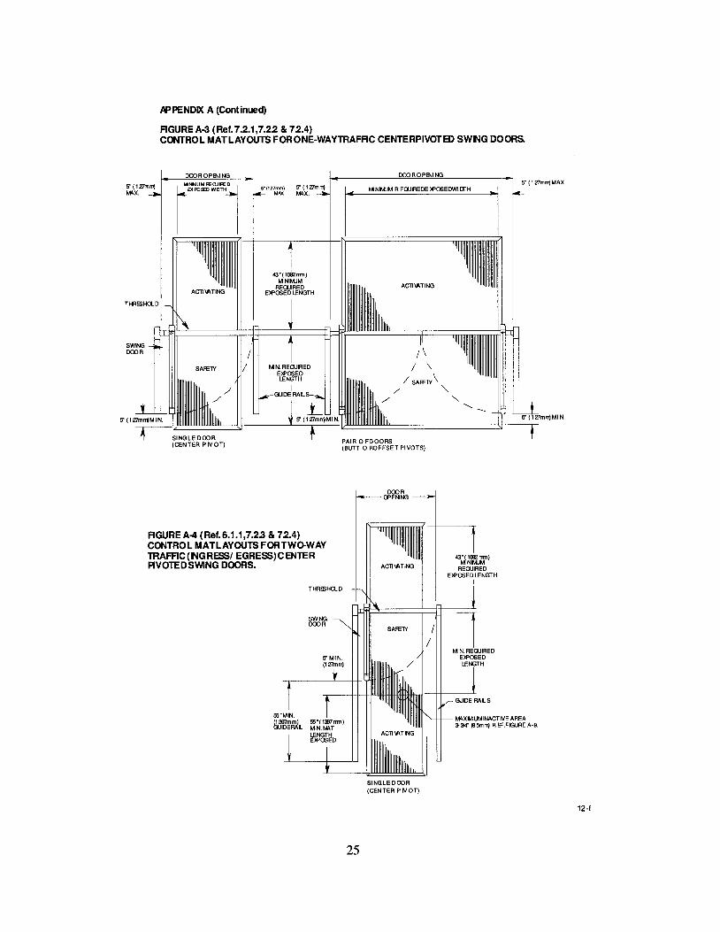
APPENDIX A (Continued)
RGUREA-3 (Ref.7.2.1,7.22 & 72.4)CONTROL MATLAYOUTS FORONE-WAYTRAFRC CENTERPIVOTB> SWNG DOORS.
S (l27mlTjMIIX.
THRESHO-D
DOOR OPENI NG
SINGLE DOOR(CENTER PIVOT)
S" (127mm) 5" (1 Zlm n1MAX ~X.
DOOROPENINGS (127mrrjMAX.
M NIMJM R EQUIREDE lPOSEDWI DrH
ACll'ATING
I/ \
/ "/ SAf£1Y"
/ "/' "
S(l27mrrjMIN.
DOOROPENING
RGUREA-4 (Ref. 6.1.1,7.23 & 72.4)CONTROL MATLAYOUTS FORTWo-WAYTRAFRC(NGRESSI EGRESS)CENTERPIVOTED SWING DOORS.
THRESHa..D
SWINGDOOR
25
MIIXIMUMINACTIVE AREA3-:Y4" (95mrrj R 8'.FIGURE A-S.
SINGLE DOOR(CENTER P IVOTI
12-(
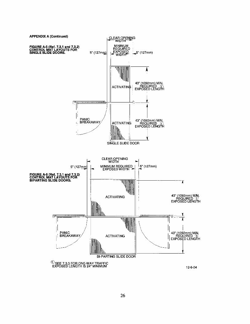
" (127mm)
CLEAR OPENIWIDT
MINIMUM
~~~~~I WIDT I
43" (1092mm) MIN.ACTIVATIN REQUIRED (f)
EXPosr LENG1fi
'-------"SINGLE SLIDE DOOR
5" (127m
II PANICII BREAKAWAYI
~
t43" (1092mm) MIN.
REQUIRED tM
~~~~~~~~====~il EXPOT LENG
LJ --1
APPENDIX A (Continued)
FIGURE A-S (Ref. 7.3.1 and 7.3.2)CONTROL MAT LAYOUTS FORSINGLE SLIDE DOORS.
12-6-04
ACTIVATING
CLEAR OPENING I~---WIDTH-----
I---MINIMUM REQU~ 15" (127mm)I EXPOSED WID I -
II PANICII BREAKAWAY
~.
r43" (1092mm) MJN.
REQUIRED ~)
EXPosr LENGTH
~~~~~~=~~~~~~
I -11 43" (10~2mm) MIN.
II REQUIRED WEXPosr LENGTH
~~~::===::'==:=========:=:=?--------BI-PARTING SLIDE DOOR
CD SEE 7.3.3 FOR ONE-WAY TRAFFICEXPOSED LENGTH IS 24" MINIMUM
5" (127mm
FIGURE A-6 (Ref. 7.3.1 and 7.3.2)CONTROL MAT LAYOUTS FORBIPARTING SLIDE DOORS.
26

APP8'JDIX A (CClltimsd)
CONTRa... MATSCROSS SECTIONS.
6" 152mm MAX. INACTIVE WIDTH
CROSS SECTON atTHRESHOLD
2-1/Z' (64mm) MAX. NACTIVEAREA WHEN MATS ARE
PERPENDICULAR mOPENNG
FIGUREA-7(Ref. 7.5.3)
FIGUREA-8(Ref. 7.5.1)
PLAN VIEW- PERPENDICULAR MATS
PLAN VIEW- PARALLEL MATS
CROSS SECTON A-A at JONT
3-3/4" (95mm) MAX. NACTIVEAREA WHEN MATS AREPARALLEL TO OPENING
CROSS SECTON B-B at JONT
FIGUREA-9(Ref. 7.5.2)
EXPOSE D ARE A
MIN. RAMP LENGTH ACllVE4x MATTHICKNESS 1-1/2' (38mm)
....1-----........ MAX. ~""'R~14INACTIVE
CROSS SECTON atSURFACE MAT TRIM
27
1/2" (13mm) MAT 1THICKNESS
FIGUREA-10(Ref. 7.1, 7.5.4, and 7.6.4)
11-1-04
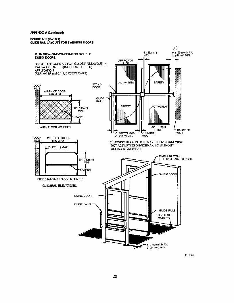
APPENDD< A (Continued)
FIGURE A·11 (Ref.6.1)GUIDE RAL LAYOUTS FORSVVlNGING DOORS
PLAN VIEW-ONE·WAYTRAFAC DOUBLESWIN3 DOORS.
REFER TOFIGUREA-2 FOR GUIDERAILLAYOUT INTWO-WAY TRAFF IC (INGRESSI EGRESS)APPLICATON(REF. A-12Aand 6.1.1, EXCEPrON#2).
Q)6" (l52mm) MAX.Z' (51mm) MIN.
ACTIVATING
6" (l52mm)MAX.
b APPROACHSIDE
6" (l52mm)MAX.
APPROACH
ACTIVATING
(f) SWING DOOR IN HALLWAY UTILIZING KNOWING)l;tT ACTIVATING DEVICEMAX 10"WITHOUTADDII'{J A GUIDE RAIL
GUIDERAL
SWINGDOOR
~" (762mm)MIN.
IDIVIDER
~"(762mm)
MIN.I
PANEL
1::' (l52mm) MAX.
WIDTH a= DOORMINIMUM
GUIDERAL ELEVATDNS.
FREE STANDNGI FLOOR MOJNTED
JAMB I FLOOR MOJNTED
DOOR WIDTH a= DOOR-J MINIMUM
SWING DOOR __.l-f+t--
11-1-04
28

APPENDIX A (Continued)
F1GUREA-12A(Ref.8.1 & 82)ACT IIfAT NG AND SAFETY DErECllONZONES-SWING DOORS,
B
REF. 8.22.2 FOR REQUIREMENT Fffi ASAFETY BEAM OR PRESENCE DETECTONON THE SAFETY 2DN E SIDE OF lH E DOOR
30"(762mm)
30"(762mm)
TWO·WAYTRAFFIC
B
ACllVA liNG --J---.....DETECTION ZONE
A =MNIMUM ACTIVATING DETECTON 2DNE LENGTH.B =MNIMUM ACTIVATING DETECTON 2DNE WIDTH.C = MINIMUM SAFETY DETECTON 2DNE LENGTH.D = MINIMUM SAFETY DETECTON 2DNE WIDTH.
A
5"MAX.
C
T-55" (1397mm)
~c
30"762mm)
30"(762mm)
30"762mm)
ACllVAliNG -t---r( DETECTION ZONEA
A
C
C
5" (127mm) 1-~__~D::""_-fo-l5"(127mm)MAX. ONE.WAY MAX.
TRAFFICNOTE: T HBJETECllONZONfPATTERNS 0 ER ClEDINTHE AED\E
ilL~m~'1.t~rm~6'~~NOTTOSCAlE)ANDFOR
11·1·04
29

FIGURE A12-A Continued
5" MAX.(127mm)
I61
- ---;;;' -f'"I -,, ', ..I '
I '\
' ... j"" 7'< - ' (204mm)L_J 5" (127mm) MAX.
A
SWINGOOOR
OOORPIVOT
MINIMUMACTIVATINGDETECTION
ZONE
I,I\ 30"I (762nvn)
'8"
\\ I\\ /
r, \\ /\~ \\ /\0\ \\ /
~/ ,,1«\«\'
~~\.,,\"
8" (203mm) MAX.D' -\ '(~.11.#\ "r------- II
~~. - r.-\LJ"-~ \.!J. ~
~
30
GUIDE RAILS
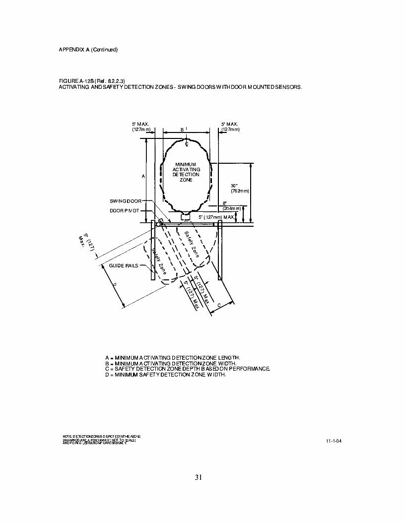
APPENDIX A (Cootimsd)
FIG URE A-12B (Ref. a2.2.3)ACTIVATING ANDSAFETYDETECTION ZONES- SWING DOORSW ITH DOOR MOUNTEDSENSORS.
5"MAX.(127mm
A
SWINGDOOR
DOOR P IVOT
MINIMUMACllVAllNGDElECTION
ZONE30"(762mm)
I, , 8"
\.... J - (204mm)e S' (127mm) MAX.
A = MINIMUM AcrlVATING DETECTIONZONE LENGTH.B = MINIMUM AcrlVATING DETECTIONZONE WIDTH.C = SAFETY DETECTION ZONE DEPTH BASEDON PERFORMANCED = MINIMUM SAFETY DETECTION ZONE WIDTH.
31
11-1-04

APPENDIX A (Cmtim.ed)
FIGUREA-12C (Ref. 8.2.3)ACTIVATING ANDSAFETVDETECTION ZONES- SWING DOORSW ITHDOOR MOUNTEDSENSORSTWO-WAYTRAFFIC.
A
SWING DOOR
DOOR PIVOT
~~
'" "::>~ ~./
GUIDE RAILS
T55" (1397mm)MIN. GUIDERAIL
LI ACllVA llNGI DElECTION ZONEI
B
TWO-WAYTRAFFIC
5"MAX.(127mm)
30"(762mm)
A = MINIMUMAcrlVATING DETECTION ZONE LENGTH.B = MINIMUMAcrlVATING DETECTION ZONE WIDTH.
SEE FIGUFE A-12B FOR SAFETYZONEDIMENSIONS.
NOTE: 0 ETECTIGlZO'lES 0 EACTEDI NTHE AlDIEDRAWlNGSARE APFR014MATE(NOf TO s::AL.EIAND FORI LLUsrRAllONP URfO~Sor-Ly.
32
11-1-04
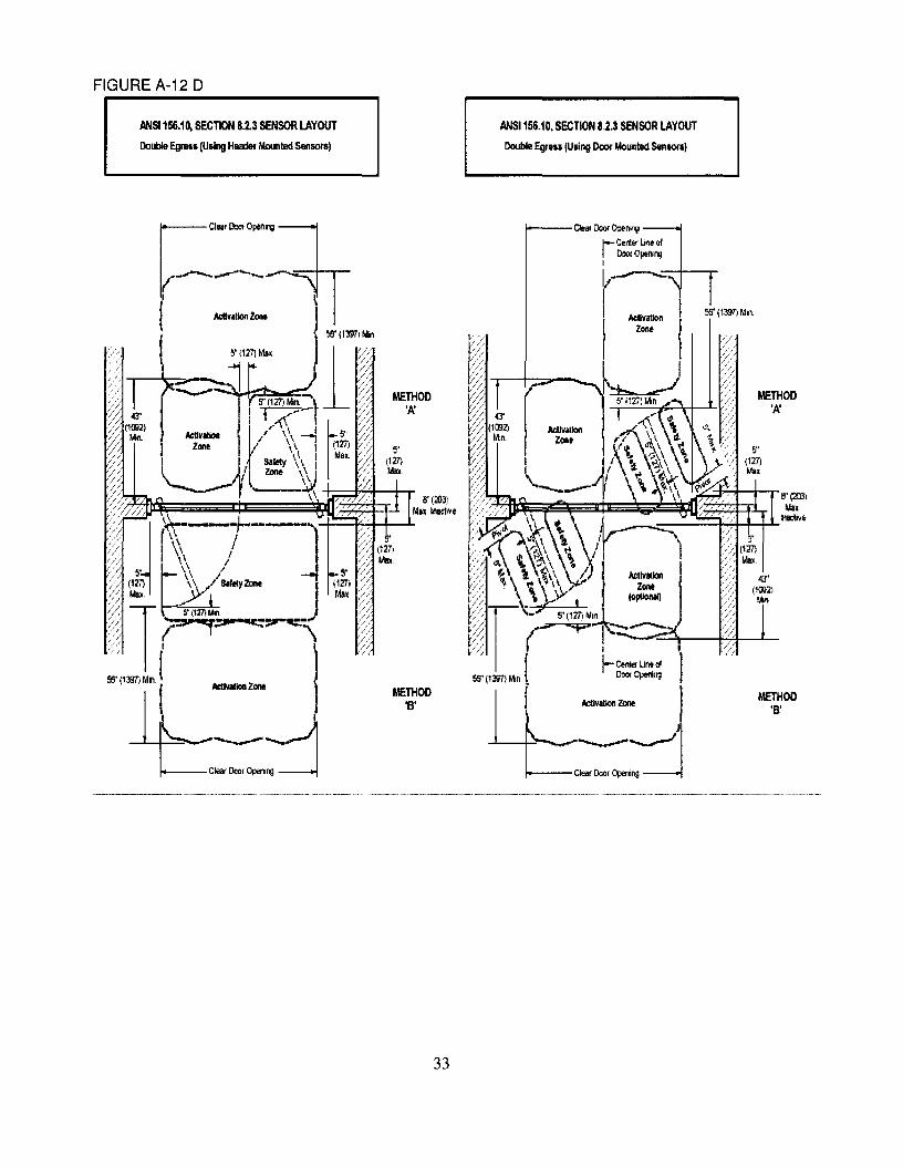
FIGURE A-12 D
ANSI 1&6.10, SECTION 8.2.3 SENSOR LAYOUT
Dollble Egrll5s(Using Huder Mounled Sensotsl
ANSI 156.10, SECTION 8,2.3 SENSOR LAYOUT
Double EgIS" (Using Door Moooted 5enSOlS)
METHOD'A'
METHOD'B'
56' (1m~ Mln~
Il'(:<m)lAin
__-+"""'I-+-+.L..lnilClive
I
I-Get'lIef UneCl000< Opering
ActIvIUon ZOOt
1---CleM DooI Op.nlllg
8"(Il3)Millt InaeIlVe
METHOD'B'
METHOO'I(
-----~--------~..~-~-~~~-~--~-~-_ .._-~---~~
33

APPENDIX A (Cmtimed)
FIGUREA-13 (Ref. 8.2)ACTIVATING DETECTIONZONES- SUDE DOORS.
MINIMUMACllVAllNGDE1£CTION
ZONE ~
... >-..~- B:::::A
I \\0I \ \JI~~III \I \
5" MAX.(127mm)
SLIDINGPANEL
A
FIXEDPANEL
A = MINIMUM ACTIVATING DETECTON 20NE LENGTH.B=MINIMUMACTIVATING DETECTON 2ONEWIDTH.
"\MINIMUMACllVAllNGDE1£CTION
ZONE
r-, 5' (127mm) MAX.--'--'-
-r--,- - ;08" (204mm) _ ....;,'....'......-.,J-_I__~5n (127mm) MAX.
1-,1" "
(0A
MINIMUMACllVAllNG
DE 1£ CTION ZONE
TWO·WAY TRAFFIC
(0 REFER T08.3.3 FOR ONE·WAY TRAFFIC
B
NOTE: D ElECTIO>IZCNES DEACTEDI NTHE ABJIEDRAWINGS ARE A PFRO~AlE(NOT TO s::ALE)ANDFORI LLusrRATlONP URRJlESQNL~ 11-1-04
34

AP PEND D( A (Continued I
FOLDING DOORSPANELLAYOUT
Figure A·14
(Ref. 5.0)
SING LE FOLDING DOOR
FS
PAIROF FO LD NG DOORS
FS= FOLD SVY'ING PANEL
FX= FOLD SLIDE PANEL
FS
GUIDE RAL LA YO UTS FO R FO LDING DOORS
FigureA-15(Ref. 6.2)
SINGLE FOLDING DOOR
Glll:le Rail
PAIRO F FO LDING DOORS
e 11"'Ili It J
[or II ~ lnlm'A'
II~Ii" 1Ii11lmlm
,'"
-J
11//!Ju-l
FfA'Uillmim
or II II InlmJ
Ii" lIallmlm
"A"=12 i nches,(3J5mm)Daar Jam b
Palel arDIIICle r
t.'I===~-,-
3 '1111.
Pan I arDillcl! r
3 ' 1111.
JAIIB AND FLOO R 110 UN TE D FREESlJ' NDNG FLOOR 110 UNTED
ll-HU
35

APPENDIX A (Continued)
CONTFOL MAT LAYOUTS FOR FOLDING DOORS
FigureA-16
(Ref. 7.4 through 7.4.4.)
CONTFOL MATLAYOUT FOR ONE- WAY TRAFFIC FOLDING DOORS
-DoorOpenirg Door Openirg- S' - -5" - - 5"1-- - 5" -t
Aclivalirg M~<TJm AclivalirgExposedL.erglh43"1- - -
I-
W MLf-
W ~I-
Safety Safetytx:;q'd
l~'t J,5"
Mi~mum Mirmum
SINGLE FQ..D1NG DOOR PAIR OF FOLDNG DOOR
CONTFOL MATLAYOUT FOR TWO-WAY TRAFFe FOLDING DOORS
DoorOpenirg- Door Openirg- 5" I-- - 5" r-- - 5" I-- - S' -f
Aclivalirg MinimJm AclivalirgReq'
1j>~td
r-
W,,,., ff-
W\~
,....
SafetyMinimumRe 'd
l~d• •S' 5"Mi~mum Mi1mum
lAclivalirg 43" Min. Aclivalirg
1
11-1-04
36

APPENDIX A (Continued)
DETECTION PATTERN LAYOUTS FOR FOLDING DOORSFigure A-17A
['~U""'"'_ rc"~o""",-4~" V Activation 4~"
Minimum ZonE< ~ IvhnllllUIll._- ....;:< --- ..., -- , --~" ,---4--- --- 1-------+--- -- -fI I
I I
I I, I 30·, --,-- ---I-.------,-- I8" t ' .. !5" Max. - - • S"lv1ax. • - -
, - ..,--- DI , , l :JI
If- _~ 5" Max. I I I I
1I I I I8"
1 I..r 1- - - - ..~_._-1:--1- - - -- 1- -,7;- + - -- -,-If S::i:,"lit I _l' f I-It:-Safety Zone _..:...
~Mi~imun~ -
f- I- --- ,5" Mi~imum I.. .
-- .. 1 __ .. '
(Ref. 8.4)ONE WAY TRAFFIC WITH APPROACH FROM NON·FOLD SIDE
(I
SING! E FOI DING DOORONE WAY TRAFFIC
SINGLE FOLDING DOORONE WAYTRAFFIC
WITH DOORS CLOSED
If=- 24"
~
rC'", 0""", • rc.~ 0""", •43" . . 43". . Activation ..
Minimum / Zone ~ Mlnllllulll#_-'-/.. #--,~ - ~ . - ~ ,.... ..___ ~ ____________ c _____t ,, ,I I, --- I ,--,-- -.-----,-----. 8" t ' •- • 5" Max. .. - - #-,
pC
w=~-" , . DI f .... Jt: ~ =::Ji-'
~. 5" Max.I- - ,,----.1.._ , ... ......wsm,~ - -/----1-Mat , I
- ~~-I Safety' Zone ~
----- I- --.-- ' 1.. '• 5"1:\ - 5"lv1inilTl~
12" _ : .....lfi..-: p... -.
..i- ,~S~'~5"
,I-- -- .
I
Secondary, Secondary, •Activation Ivlat , Activation Zone ,.. ....- - .. - ....
I24" 5"-1
~SINGLE FOLDING DOOR
ONE WAY TRAFFIC
SINGLE FOLDING DOORONE WAY TRAFFIC
NOTE: DETECTION ZONES DEPICTED IN THE H30VE
~1I~~miT~rg:Jtf'~~ lflLFf/lLE) WITH DOORS OPEN 12·6-04


APPENDIX A (Continued)
DETECTION PATIERN LAYOUTS FORFOLDING DOORS
Figure A·17C (Ref. 8.4)
StlGLE FOLDtlG DOOR
TWO WAY TRAFRCPAIR CF R:>LIlNG DOORS
TWO WAY TRAFFIC
laea~pen.,~ ~aear~.,g:J
Millmum Mill mum, ... _ .. ActivalionZore _, _. "r:.--- ,,' ---'~ -- -5"- -- --: ------ - -~, :--0--
1M '\ , Max. 1 ,
30'1" r - ~,---- ---r r - -,- -. - - --,-----1-____ .. _ ,.,,' 8" ~- ... - _ • til - " _ - --,
~+!=Pe±::~t=::ft::===¢:P~=l=i:t:P:~~=:::ft=====:"'C====::Jt=+~±,IC
~ -tr)~---'~ -t[-fql#-~--"----"---"-"'~L- ::I//safetYZore ~ ~x._~. 1L! _ ~etYZore __ liL
~-==---i..= ---r • .1. _
~'\ ,~M~im~m-~" ~'_ 5"MI:: ... --J11- - """..._. C ~_ I
~ ~ ,-' -- -- \----;- ~-:-I:- ~ {- -- -- -- --'~~" .. ActziVonalei,on ~ 1__ IMi:.[Um __ ~ Activalion ~ r--..----. _ ~ ~,....- ~one ~~ --102---- -,--.--
WITH DOORSCLDSED
StiGLE FOLDtiG DOORTWO WAY TRAFFIC
PAIR CF R:>LIlNG DOORSTWO WAY TRAFFIC
IIIe
i r11 / / ,,-- .., 8" T ~1 I / - - .- - - - - - ... \ \ 1
30" 1[1 irf-,- ----T 1. l -t --+1/+ l- - - -'IT\~'-,--l--lH---Y,L/ !.safety Zore~ ~x. _ Max. Ll': Safety Zore _' IJd-
1 .~. ' ~ .~ ,_ "" ~ 5"~n~ "" i"'" • _ 1_'.. _ 5" Me _"! I "~"I-• .J_c,'""'l" - 5"~ __,~ I,_-l5
-- 8" + - - ,- -'. - ,-- ,- -- -- '--. '"iJ~:- -- +- -- -- -- -- ~ -'. Activalion 1 IMi ri mum ~. Activalion ,
.. Zone ~ ---l::::1 __ ----.19"e__~~-',---::--~ -- y-- -- -~ -.-."- .,,-~
r.Clear~~in~ ~aear~ng:]
Mill mum Mill mum
." - - ... Activation Zore t#'" .- - - - - - " .....
~ -- T--- '~ -- -5"- -- --: -- -- - - --' :
i" Mr -- -------, - -- ,L -rMf- - --\-- -- . - -- ----:-~ -1-__..., "_ -' ~ I .... ,-,-.----,
WITH DOORS OPEN
IF ON E-WAY TRAFFIC1. fION R)LD SIDE REDUCE TO 24" MINIMUM2. FOLD SIDE REDlICE TO 24" MINIMUM
NOTE: 0 ElECTICJ'IIZQI.IES 0 EACTEDI NTHE ABJ\EDRAWINGS AREA PffiOJ4MA1E(NOf TO S::ALE)ANO FORI LlUSfRAllONP URR)fESQNl V.
12-6-04
39
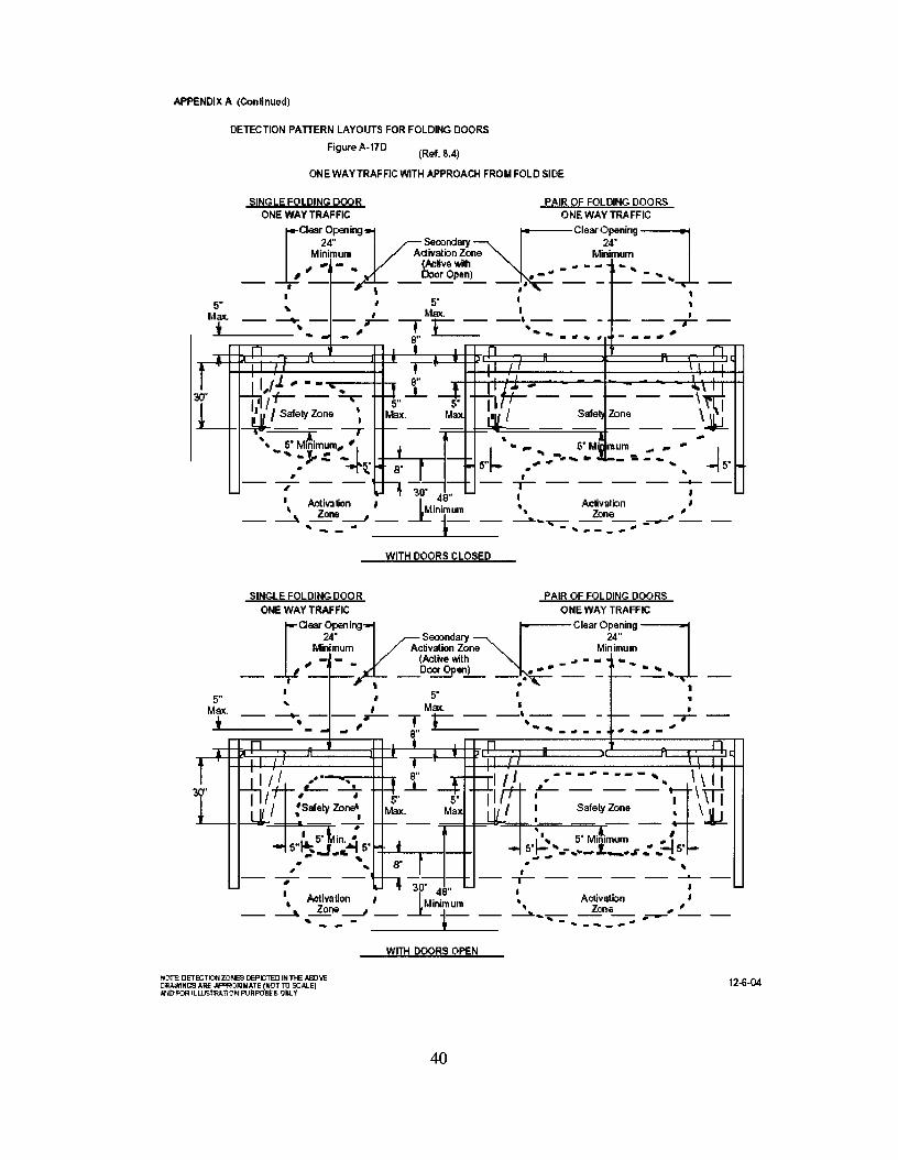
APPENDIX A (Continued)
(R.ef.Il.4)
ONE WAYTRAFFIC WITH APPROACH FROM FOLD SIDE
DETECTION PATIERN LAYOUTS FOR FOLDING DOORS
Figure A-l1D
5"Max.i
SINGLE FOLDING DOOR PAIR OF FOLDING DOORSONE WAY TRAFFIC ONE WAY TRAFFIC
la::~t:k~~~~:~~~Clea:~~::g:J"..... (Active with .. _ .. .. .. .. .. _
__ " _~. __D:lorOpe!i- __ ,,- f-- ~ .., 'I I 5' I 1.. I Max. I :-- ~ - -- " 'C-= --\-- -- - I-- -- --.-
...... -~ S" ... ~_.~~ --_."..
1. 11,/1 ... --~.. ,r .. -ll::~- \010.\'\11i 11":1/t- - - ..- 5" ~ If ,/ "N"'jt .1 11 , Safety Zone ~ Max. Max ~ , Safell Zone \l,L-"---+-I~ - - ---, - - =r=~F'ilt:::::::=-==--==..J:--- - - ...
...... ~·M~i~~m".'1 of I .... - 5·M~mum ..... '" I,:'- "':.t(foo S· r ~ 5"1- : ~ J __ ':. -........ -15'
-- --,- -- -- .. -, 30' 48" --.-- -- -- -- -- ~
\ Ac~ivation, IMinimum ~. _ ..~ A~~_b_n " ,,'~ ---E,.ne ---.J __ -.r: ~.__ __ _ ~ _ ~
, ... _.. J - .. ~-_ .....
WITH DOORS CLOSED
•
SINGLE FOLDING DOOR PAIR OF FOLDING DOORSONE WAY TRAFFIC ONE WAY TRAFFIC
la:i~r~~kJ=~~~n~Clear:~~~n~:J
' - - _ (Acl;"e\\ilh .. -.. .. ...__ , _ _ __Dca Open..L.... __ ., .... -__ _ _ .:...::. ..
" .5" I I 5' I :
Max. _" '--r Mr __I, __ _ '* -- •---.-- , t.. -- - -- -r-......----- - .... ~, 8" ...... _~-- ...... -.,
1L J
-,-
f -}ill,.....W' "T I- '- -"1 I I, :safe~ Zo~......-+-I-1l ~" __I,
I 5'~in "- 5"~J...~~ 5'1-I-~+.....--1_-1-1
.. ... r" .. S"
h 30' 48"\ Activation, IMinimum~ ... Zone ---.J -- -i: 1-- -- • Activatbn
.. Zone~ ....-..--- ...---...- --...- ..
," '....- --
WITH DOORS OPEN
12-6-04
40

APPEtI)l)( A (Contilued)
A-18A (Ref. 8.3.2.1) VERllCAL SECTIQII· SLDE DOOR SHOWtlG ACTIVATtiG DETECTION ANDPHOTOELECTFIC BEAM ZQII ES (4 m1rimum).
ACllVATlNG --~DETECTION ZONE - 2.5SECOND M N. TIMEDELAY
B
3" (76mm) MAX. FROMCENTERUNE OFSLDING PANEL
TOP PHOTOELECTRIC BEAMLOCATED BElWEEN55" (1397mm) AND45" (1143mm)
OTHER BEAMS LOCATEDNOT GRE ATER THAN6" ( 152) -1 Z' (3C5mm) AP ART
BOTTOM PHOTOELECTRICBEAM LOCATED BETWEEN28" (711m m) AND 6" (152m m)
A = MAXIMUM DISTANCE 10 ACTIlfATlNG DETECTION ZONEB =43" MINIMUM
A-18B (Rei. 83.2.2) VERTCALSECTION· SUDE DOOR SHOWtlG ACTIVATING ANDPRESENCE DETECTION ZONE lliROUGH DOOR OPENtiG.
ACTIVATINGDETECTION ZONE 1.5SECOND MN. TIMEDELAY
PRESENCEDETECTION ZONE
SLDINGDOOR PANEL
NOI"E: oElECTICNZCNES 0 EACTEDI NTHE AID\£DRAWINGS ARE APFRO~MAlE(NOTTO s::ALE)A~ FORlU.usrRAlIONPURR)!ESCNL Y.
C
PH010ELECTRIC BEAMSAS SHOWN ARE REQUIRED IF PRESENCEDETECTION ZONE IS DEACTIVATED WHENDOOR STARTS TOCLOSE.
TOP PHOTOELECTRICBEAM LOCATEDBETWEEN55" (1397mm) AND45" (1143mm)
BOTTOMPH010ELECTRICBEAM LOCATEDBETWEEN28" (711mm) AND6"(152mm)
A = MAXIMUM DISTANCE 10 ACTIlfATlNGDETECTlON ZONEB =MNIMUM PRESENCE DETECTION ZONE WDTH (SEE 83.2.2)C = 43" MINIMUM
12-6-04
41

APPENDIX A (Continued)
A-1/1; (Ref. 8.32.3) VERl1CALSECl1ON· SLDE DOOR SHOWn'1> ACl1VAl1NGANDPRESENCE DETEC"TlONZONE ON EACHSDE OF DOOR.
ACllVAllNGDElECTION ZONE 1.5SECOND M N. TIMEDELAY
PRESENCEDElECTION ZONE
SLOINGDOOR PANEL
C
PHOlOELECTRIC BEAMS AREREQUIRED F PRESENCE DElECTIONZONE IS MORE THAN 3" FROM FACE OFDOOR
TOP PHOTOELECTRICBEAM LOCATEDBETWEEN55" (1397mm) AND45" (ll43mm)
BOTTOMPHOlOELECTRICBEAM LOCATEDBETWEEN28" (711mm) AND6" (l52mm)
A; MAXIMUM DISTANCE 10 ACTIVAllNG DETECllON ZONEB; MAXIMUM DISTANCE 10 THE PRESENCE DETECTION ZONE (SEE 8.3.2.3)C; 43" MINIMUM
A-1lD (Ref. 8.32.4) VERl1CALSECl1ON • SLDE DOOR SHOWlfIG ACl1VAl1NG DETECl10N ANDPHOTOELECTRC BEAMONE SIDEANDP~SENCEDETECl1ONZONE ONOTHERSIDEOFDOOR.
ACllVAllNGDElECTION ZONE - 2.5SECOND M N. TIMEDELAY
PRESENCEDElECTION ZONE
SLOINGDOOR PANEL
C
NOTE: DE1EGTlCNZalES D EACTEDI NTHE AID\EDRAWlNGSARE A PFROl4MA1E(NOT TO s::ALE)AND FORI LLUsrRA1lONP URFOiESCN..Y.
3" (76m m) MAX. FROMCENTERUNE OF SUDNGPANEL
TOP PHOTOELECTRICBEAM LOCATEDBETWEEN55" (1397mm) AND45" (ll43mm)
BOTTOMPHOlOELECTRICBEAM LOCATEDBETWEEN28" (711mm) AND6" (l52mm)
A; MAXIMUM DISTANCE 10 ACTIVAllNGDETECllON ZONEB; MAXIMUM DISTANCE 10 THE PRESENCE DETECTION ZONE (SEE 8.3.2.4)C; 43" MINIMUM
12-6-04
42

'l'ELESCOPINGSLIDING DOORAlIEP'ERUA
SENSOlt APl'LICA'IION
._.,--~ ._-- --- -,..--- .~_."'- --
Al'nseIlctDnec:tiE
nJricWln'P .Oftrllead PreslBKeSemor w Belllll!perU.4
A. lfa1imam:5" JudiftBtMre Adina. ZoIIf
B. llDimal3" Iudift.Vu Betwelm E1ce afDlarPmelULd PHStIICf DetKtiaa
C. lfuimDm1000.bKtMAm BetweB Pire:seJD DeUdima
1. Fast SlidePael (l.nd DD«) 'X' .. SIilIt-S1riag 'SX'
1. sr.w Slide PEel (Su0llduyDear) 'r or SlD-SwiBg'SX'
3. SideIite (NiaJI-SIid2) '0' GI'.~ 'SO' or Wall 'P' for S1Irf.Ke Applied.
43
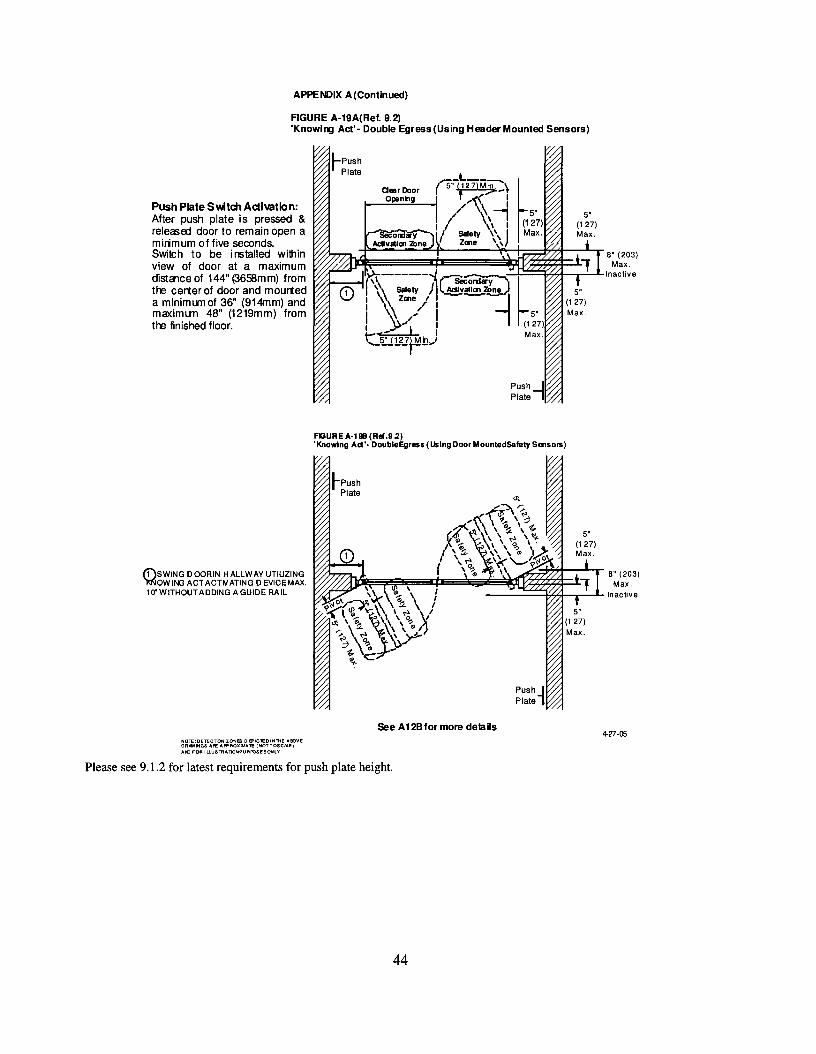
APPENDIX A(Continued)
FIGURE A-19A{Ref. 9.2)'Knowl1lJ Act'- Double Egress {Using Header Mounted Sensors)
Push Plate Switch Adivation:After push plate is pressed &releasoo door to remain open amirimum of five seconds.Switch to be installed withinview of door at a maximumdistalce of 144" (3658mm) fromthe cerner of door and mourteda minimum of 36" (914mm) andmaximum 48" (1219mm) fromthe finished floor.
fi)SWING 0 OCRIN HALLWAY UTIUZING):)<low ING ACT ACTIV ATING 0 EVICE MAX.10'WITHOUTADDING AGUIDE RAIL
I'"'C-t._--:::--,,\aesrDoor r 5" (127)M.jg,;._~
O~n~g ~~'~;>-l/' \!
I I \ I5eCord..,y--- I Safety \ \ J
AcIIvslloo 2bne Zooe \ \
FGURE A-191l (REI.9.2)'Knowing Act'· OoubleEgress (Using Door Mounled5afety Sensors)
NOTE:DETECOON ZONES 0 8"ICTEDI NTliE ABOVEORNNINGS "'FE APPROXIMATE (NOTTOSCIt.E}AN) FOR I LLUSTllATlONPUAPOseSONlY.
See A128 for more dela ils4-27-05
Please see 9.1.2 for latest requirements for push plate height.
44

Appendix A (Continued)
AGUREA·19C (Ref. 9.2)'Knowing Act'· Double Egress (Using Control Mats)
5" (127) Min.
Note: See 7.5lor t1Yesholdrequirements.
-~
Secondary LActivation Mal
~ 5"(127Max_
II
I
/
~~-
5"9r /\'r/ "(127) / ,\Max. r-------l / \ \
j safely,'Secondary " Mat ,\
ActlvaUonMat , ,
Push Plate Switch Activation:After push plate is pressed &released door to remain open aminimum of fiveseconds.Switch to be installed withinview of door at a maximumdistance of 144" (3658mm) fromthe center of door and mounteda minimum of36" (914mm) andmaximum 48" (1219mm) fromthe finished floor.
SEE DETAlLA7 FOR THRESHOLD DETAIL
45
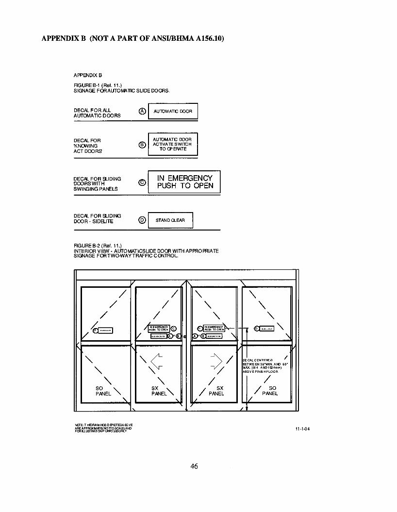
APPENDIX B (NOT A PART OF ANSIIBHMA A156.10)
APPENDIX B
FIGURE B-1 (Ref. 11.)SIGNAGE FOR AUTOIvlATlC SLIDE DOORS.
DECAL FOR ALLAUTOIvIATIC DOORS
® I AUlOMATC DOOR I
DECAL FOR'KNOWINGACT DOORS
DECAL FOR SLIDINGDOORS WITHSWIr--GING PANELS
®
©
AUlOMATC DOORACllVA1E SWITCH
TOCPERATE
IN EMERGENCYPUSH TO OPEN
DECAL FOR SLIDINGDOOR - SIDELITE ® I STAND U-EAR
FIGURE B-2 (Ref. 11.)INTERIOR VIEW - AUTOMATICSLlDE DOOR WITH APPROPRIATESIGNAGE FORTWO-WAY TRAFFIC CO\lTROL.
V .1\
/ / " '\/ / " '\
/ / " "L ~
dINEMeGENCf~~"/I~~M~~~ I(§)
/~ .~
/ ~r{ ~r®.,..,".. 1 '\ '\vf\ 1'\ V ~
'" ,,~ )/ DECAL CENTERED /BETWEEN 36-MIN. AND 60·
'"MAX. (914 AND1524mm)
" / ABOVEFINISHFLOOR
'" " / /SO '" SX "
/ SX / SOPANEL PANEL PANEL 1/ PANEL
'" "- /
I ... /
46
11-1-04

APPENDIX 9
FIG URE 9-3 (Ref. 11.)SIGNAGE FORAUTOMATIC SWING DOORS.
DECAL FO RALLAUTOMATIC DOORS
DECAL FO R'KNOWINGACT 000 RS'
~ I AU1CIIATC DOOR I
AUTO II ATC DOO RACTntA 1C SllIIllC H
TO OP EMTE
®DECAL FORONE-WAYTRAFFIC
®DECA. FO RTWO-WAYTRAFFIC lIl\IfINlIiIlOl!
DECAL FOR DOUBLE EGRESS DOORS: KNQl.i\ANG ACT USE A,B, C NON KNOVVING ACT USE A, D
FIG URE 9-4 (Ref. 11.)INTERIOR VIEW - AUTOMATlCSWING DOORS W ITHAPPROPRIATESIGNAGE FO RON E-WAYTRAF FIC CONTRO L.
1
--- -- -- f--- -- -- --/ '\
/ '"/ '"/@~ 0@",/~,~c: ~ ~'€lI·_..-1 \
'\ i/
'" /
'" /
'" /'IN' '"
/'OUTDOOR "- / DOOR
47
TOI! e.>.L& e!N''''' I!IlAT l!l!I·t l!I·lloilWi :tl:nt"Il'I"l)" !lOY!~1oIH I'U>O~
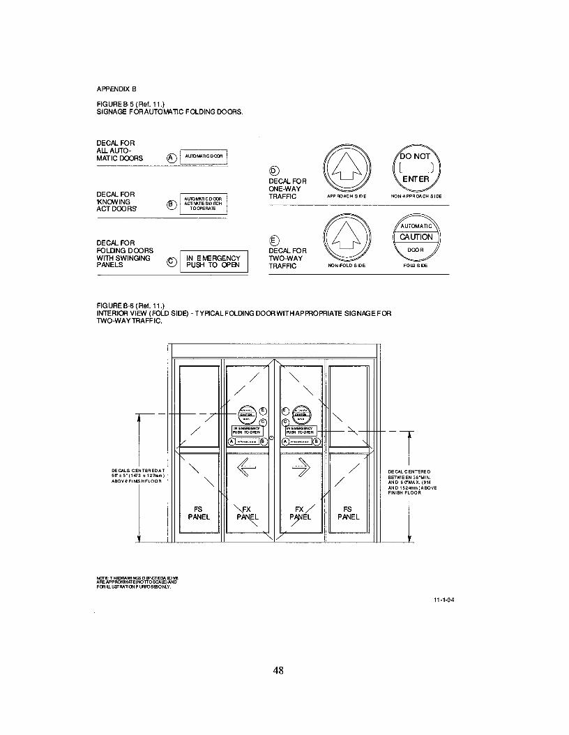
APPENDIX 8
FIGURE 8-5 (Ref. 11.)SIGNAGE FORAUTOMATIC FOLDING DOORS.
DECAL FOR
©All. AUTO- ([) I AuroM\~CDcm IMATICDOORS
C0DECAL FORONE-WAY
DECAL FOR TRAFFIC APPROACH BilE NON-APPROO!CH SIDE'KNOWING @)ACT DOORS
©DECAL FOR @)FOLIlNG DOORS DECAL FORWITH SWINGING 8 IN EMERGENCY TWO-WAYPANELS PUSH TO OPEN TRAFFIC NON.f'OLD SIDE FOLD SIDE
FIGURE 8-6 (Ref. 11.)INTERIOR VIEW (FOLD SIDE) - TYPICAL FOLDING DOORWITHAPPROPRIATE SIGNAGE FORTWO-WAYTRAFFIC.
DE CAL C EN TERE 0BETWE EN 36~tvUN.
AND 6 O"MAX. (914AN 0 1524mm )A BQVEFIN ISH FLOOR
J
/ '"/ '"r- -7 -~~ ()@'"mo. (C'J I(C") mO'
/ I~~M~~~ I I~N EMERiENCr'~PUSH TOOPEN
V A ........ B ®...m ...·I@ "-
r--
~ ~ENTEREDAT '" /3t127mm)
'" /ISHFLOOR
FS VX FX/ FSPANEL P~ ~EL PANEL
/
DECALS C58" tS" (147ABOVE FIN
NOTE:T HlDRAWINGS DEPICTEDA BJVEARE APPROXIMI<TE(NOTTOSCALE) ANDFOR ILLusrRA~ON P URfQSBSONLY.
11-1-04
48

APPENDIX C (NOT A PART OF ANSIIBHMA A156.10)
DEFINITIONS OF TERMS AS USED IN THE POWER OPERATED DOOR INDUSTRY.
Air Lock Air space between doors such as in a vestibule where only one door or set of doors can beopened at one time.
Approach Beam Photo-electric control beam used to activate an automatic door.
Automatic Entrance Package Complete entrance way containing door(s), frame, controls, andautomatic operator.
Bi-Parting Sliding Doors A pair of door leaves sliding away from each other to form a singlecommon door opening.
Bottom Arm (Hardware). The arm mechanism attached to the bottom rail of a door and connectingto the spindle of a floor closer, pivot or automatic door operator.
Break Out Opening The clear space in a doorway when a swinging or sliding door is operated in theemergency mode. This opening is not necessarily the same as the clear opening in the doorway whenthe door is operated in the normal mode.
Break Out Side The side of the opening to which the door swings when broken out.
Concealed Mounting Automatic door operators which are mounted above or below the door andpower the door through an inconspicuous pivot or arm.
Cover Plate In reference to door hardware, a finish plate used to cover the exposed face of a floorcloser not covered by the threshold; also a plate used to cover the exposed face of a closer or automaticdoor operator mounted in the head of the door frame.
Door Arm A device which is usually located in the top or bottom rail of a swinging automatic door.The function of this device is to provide suitable connection of the automatic door operator to the door. Itis concealed, semi-concealed or surface applied.
Door Light The glass area in a glazed door.
Door Size (Actual) For swinging or sliding doors, the actual width and height of the door leaf itself.
Flush Glazing A method of setting glass whereby glazing beads are recessed and flushed with the edgeof the frame.
Guard Bar. A protective bar applied to the lower portion of a door or sidelight to prevent collisionwith the glass.
Harness. A combination of wires and connectors providing connection of electrical controls tooperating equipment.
"In" Door. An automatic door installation designed for traffic into a building, space, etc.
In-Header Operator. A door operator completely contained in the door header requiring only electric,pneumatic or hydraulic power.
Left Hand Traffic. The traffic routing when the entrance door is placed to the left of adjacent exitdoors as viewed from the outside.
49

Lintel A horizontal structural member spanning an opening at its head to carry construction above theopening.
Masonry Opening. The wall opening into which the door is installed.
Meeting Stile The vertical edge of a door or window, in a pair, which is adjacent to the other door orwindow. A parallel meeting stile is one which has a beveled edge paralleling the edge of the door. Around meeting stile is one having a rounded edge.
Neolite Material is available from Biltrite Corp., P.O. Box 9045, Waltham, MA 02254.
Opening Cycle Movement of a swinging or sliding door from closed position to fully open. Forswinging doors, this is normally 90 degrees.
"Out" Door. An automatic door installation designed for traffic out of a building or space.
Photoelectric Control A device which employs the use of a visible or invisible light beam across orthrough an opening. When the beam is interrupted by a person or object, a signal is generated.
Power Closing. The closing of a door by energy supplied from hydraulics, pneumatics or electricity.
Power Open The opening of a door by energy supplied by other than manual means.
Power Unit A remote mechanical device used to convert energy (usually electrical) to pneumatic,hydraulic, or mechanical energy for transmission to the actuator.
Pressure Relief. A safety device to guard against excessive pressure buildup. Usually withreference to pneumatic or hydraulic systems.
Prismatic Prismatic doors are used to identify bi-parting sliding doors that meet at an inside angle ofless than 180 degrees.
Pull Cord Switch A switch located above the doorway having a cord with handle extending downto approximately 6 feet above the floor. When the cord is pulled, a switch is closed and a signalgenerated which can be used to activate an automatic door operator.
Recessed Frame (Setting Frame) A frame set into the floor during construction which secures matsinto a frame provide flush condition between floor and mat surface.
Recycle A mode of operation of an automatic door operator that occurs when the door is in the closingportion of its travel and is actuated causing the door to immediately reverse and go to the open position.
Right Hand Traffic The traffic routing when the entrance door is placed to the right of adjacent exitdoors as viewed from the outside.
Self-contained Operator An automatic operator in which the actuator and the power unit are made as asingle unit.
Sequential or Latching Operation Operation of push switch to actuate and push switch to de-actuate.
Setting Blocks Small pieces of neoprene, lead or other material which are placed under the lower edgeof a sheet of glass to support it within a frame.
Single Slide Automatic Door An automatic door which has one sliding leaf, either left hand or righthand.
Sliding Left Hand Automatic Door. Automatic sliding doors are said to be left hand when the door isviewed from the break out side of the opening and it travels to the left side of the viewer to open.
50
Sliding Right Hand Automatic Door. Automatic sliding doors are said to be right hand when the dooris viewed from the break out side of the opening and it travels to the right side of the viewer to open.
Spring Closing The closing of a door by energy supplied by springs.
Strike An opening or retaining device provided in a frame, threshold or in the edge of a stile of aninactive door to receive a lock or latch bolt. (Also referred to as a Keeper or Strike Plate).
Synchronized Operators Operators connected together either mechanically or electrically forsimultaneous operation. (Synonyms - coactive, simultaneous.)
Trim, Recessed Mat. Material installed around the perimeter of a control mat securing it recessed intothe floor.
Unknowing Act. Activating a door operator, such as pressing a switch, without specific knowledge ofhow it is done or what will happen.
Variable Time Delay A device which is adjusted to change the time a door remains open, after removalof the activation signal.
Visible Mounting Automatic door operators which are mounted above the door, protruding from thewall, and drive the door with a visible bracket and arm are said to be visibly mounted.
Definitions of other terms are found in the American National Standard for Nomenclature for Steel Doorsand Steel Door Frames, ANSI A250.7, and in the other ANSI/BHMA A156 Series of Standards.
51

APPENDIX D (NOT A PART OF ANSIIBHMA A156.10)
Dl. REFERENCE TO OTHER STANDARDS
D1.1 When power operated fire doors are used, they are subject to the requirements of the Standardfor Fire Doors and Windows ANSIINFPA 80.
D1.2 Glazing in doors are subject to criteria in the Standard, Performance Specifications andMethods of Test for Safety Glazing Material Used in Buildings, ANSI Z97.1 or CPSC requirements.
D1.3 Where required by the authority having jurisdiction, products meeting the requirements of thisStandard shall also comply with applicable local building code requirements.
APPENDIX E (NOT A PART OF ANSIIBHMA A156.10)
E-1 CONFORMANCE CRITERIA
Certification that products offered meet the requirements of this Standard and conform to individualmanufacturer's drawings, specifications, standards and quality assurance practices are available and insome circumstances are required. Buyer requirements determine the need for proof of conformancesuch as first article inspection, test laboratory reports, or listings. Specifiers requiring assertions ofconformance utilize statements of conformance by individual manufacturers, or test reports acceptableto the buyer.
E-2 PRESERVATION, PACKAGING AND PACKING
Unless other arrangements between buyer and seller are made, preservation, packaging andpacking shall be sufficient to protect containers and their contents under normal shipping and handlingconditions from the source of supply to the destination point.
E-3 MARKING
Unless other arrangements between buyer and seller are made, marking shall be in accordance with theindividual manufacturer's standard practice.
E-4 MAINTENANCE
Automatic pedestrian doors require periodic maintenance and inspection to ensure compliance withthis standard. It is strongly recommended that all automatic pedestrian doors be inspected at the time ofinstallation, and at a minimum annually thereafter, by an inspector certified by the AmericanAssociation of Automatic Door Manufacturers (AAADM). It is also recommended that the doors bemaintained on a regular basis by a qualified professional per the manufacturer's instructions. AAADMencourages compliance to current standards at the time of service.
E-5 RECOMMENDED PRACTICES AND OTHER INFORMATION
Sensors The intent of this standard is to provide reasonable safety to humans. To establish sensorcompliance, human characteristics are required. Humans have instincts to protect themselves thatcannot otherwise be duplicated.
Sensor mounting varies from one installation to another, and field tests should be conducted on eachinstallation. AAADM has established a sensor walk test as part of its training of inspectors forcertification to this standard. The method is to use humans to conduct the walk test.
It is recommended that the AAADM procedure be used to establish sensor compliance with thisstandard. If new methods are determined AAADM can adopt them at a shorter cycle than it would taketo establish procedures through this standard.
52

This revision of the standard allows for reducing the Activating Zone Length below the required 43"length due to physical restrictions or environmental conditions that make it impractical to comply withthe 43" approach.
The exception will allow more automatic doors to be installed that may not qualify without theexception and is needed to expand the use of automatic doors for accessibility.
Examples that make it impractical or ineffective to comply with the 43" minimum activating length aredoors that are installed in a storefront with a narrow sidewalk or the inside of a store with conditionsthat are tight and cross traffic not intending to use the door would cause high recycle resulting in loss ofheat, AC or uncomfortable temperature control to the building and its employees.
Shorter vestibule depth may be desirable to create an airlock but doors spaced as normallyrecommended is not available. The shorter activating zone length can be placed inside the vestibule tohelp create a better air lock
Under these conditions the standard allows activating length to be reduced to 30" minimum and a"Caution Automatic Door" sign is required to be applied to the operating door panel.
Also where conditions exist as described above, another option is to follow the Knowing ActActivation where the re-activating zone can be reduced to 24" but in this condition the door must firstbe activated by a Knowing Act Switch such as a common push switch which would than tum on theactivating sensor/mat and across door presence sensors. This method has application in hospitalinteriors at a cross isle or other locations or where card access is required for security control.
Knowing Act Activation The knowing act switch should:
• preferably be located within one to five feet from the door; but never more than twelve feet.
• remain accessible from the swing side when the door is opened.
• not be located in a position where the user would be in the path of the moving door.
• be mounted so the user is in full sight of the door when activating the switch.
• have a installation height of a minimum of 24 in. and a maximum of 48 in.
• Fixed non-contact switches should have a detection range no greater than 12 in. (305mm) toensure a knowing act is utilized to activate the door.
Consult A1l7.! and other applicable building codes for additional information regarding accessibilityrequirements for the door and area around the door.
53

Vestibule depth Vestibule depth should be a minimum of 10 feet between doors to keep sensors ormats from overlapping and to give some degree of air lock.
Double Egress Swing Doors Added to the Standard in the 2005 edition. Their primary use is inhallways of office or hospital buildings where an automated door is needed. They are similar toKnowing Act Doors except due to location, use and type of user, a separate section was added toaddress preferred practices.
Two-Way traffic Caution In general, it is not recommended to design traffic flow for two way trafficthrough an automatic swing door. The better choice is an IN-OUT swing door, automatic sliding door,or folding door. However, where it is necessary due to space constraints, or to preserve an entrance forhistorical reasons, the standard provides the best practice.
Custom Installations The following comments are provided for guidance recognizing there will becertain installations that will require deviation from the Standard requirements. It is important toobtain guidance and approval from qualified experts. Slower speeds and lower forces should beconsidered to compensate for other variances.
Examples include but are not limited to:
• Special security installations such as airport checkpoints or government buildings.
• Historical or other existing buildings.
• Heavy draft and stack pressures.
• Security grilles needed to protect the automatic entrance during the night. Placement of guide railsin the required position may interfere, necessitating setting the rail back an inch or so.
• Air locks in office buildings with high stack pressure needed next to a revolving door foraccessibility.
These should be countered by additional caution signage or sensors, restricting traffic, or reducing thedoor speed in both opening and closing. Activating zone, opening and closing force, speed, and safetyzone requirements should be considered.
Determination of sliding door closing speeds Typical 48 inch aluminum door panels with JA glassdo not exceed the 160 pound weight limit established in 10.1.1. Double glazed or stainless steel claddoors do exceed the limit, and the closing speed need to be adjusted. For example, a 200 pound doorwould be set to a closing speed of 1.25 seconds per foot maximum; a 250 pound door would be set to aclosing speed 1.5 seconds per foot maximum. See formula in 10.1.
54


![INDEX [] and Machinery... · ansi standard 1792–1816 ... ansi b4.2 642, 644, 646, 648–655, 657. index 2559 ansi b4.4m 656 ansi b47.1 1882 ansi b5.18 920, 922–924 ansi b6. 7](https://static.fdocuments.us/doc/165x107/5aa7faa47f8b9aee748cbd3f/index-and-machineryansi-standard-17921816-ansi-b42-642-644-646.jpg)