
American National Standard For Portable Primary Cells and ...
64
ANSI C18.1M, Part 1-2001 Revision of ANSI C18.1M, Part 1-1999 American National Standard For Portable Primary Cells and Batteries With Aqueous Electrolyte— General and Specifications Secretariat: National Electrical Manufacturers Association Approved April 20, 2001 American National Standards Institute, Inc.
Transcript of American National Standard For Portable Primary Cells and ...
ANSI C18.1M, Part 1-2001 Revision of
ANSI C18.1M, Part 1-1999
American National Standard
For Portable Primary Cells and Batteries With Aqueous Electrolyte— General and Specifications
Secretariat: National Electrical Manufacturers Association Approved April 20, 2001 American National Standards Institute, Inc.

ANSI C18.1M, Part 1-2001
This page intentionally left blank.

ANSI C18.1M, Part 1-2001
i
American National Standard
Approval of an American National Standard requires verification by ANSI that the requirements for due process, consensus, and other criteria for approval have been met by the standards developer. Consensus is established when, in the judgment of the ANSI Board of Standards Review, substantial agreement has been reached by directly and materially affected interests. Substantial agreement means much more than a simple majority, but not necessarily unanimity. Consensus requires that all views and objections be considered, and that a concerted effort be made toward their resolution. The use of American National Standards is completely voluntary; their existence does not, in any respect, preclude anyone, whether he has approved the standards or not, from manufacturing, marketing, purchasing, or using products, processes, or procedures not conforming to the standards. The American National Standards Institute does not develop standards and will in no circumstances give an interpretation of any American National Standard. Moreover, no person shall have the right or authority to issue an interpretation of an American National Standard in the name of the American National Standards Institute. Requests for interpretations should be addressed to the secretariat or sponsor whose name appears on the title page of this standard. Caution Notice: This American National Standard may be revised or withdrawn at any time. The procedures of the American National Standards Institute require that action be taken periodically to reaffirm, revise, or withdraw this standard. Purchasers of American National Standards may receive current information on all standards by calling or writing the American National Standards Institute, 11 West 42nd Street, New York, NY, 10036, phone 212-642-4900.
Published by
National Electrical Manufacturers Association 1300 N. 17th Street, Rosslyn, VA 22209
Copyright 2001 by National Electrical Manufacturers Association All rights including translation into other languages, reserved under the Universal Copyright Convention, the Berne Convention for the Protection of Literary and Artistic Works, and the International and Pan American Copyright Conventions. No part of this publication may be reproduced in any form, in an electronic retrieval system or otherwise, without the prior written permission of the publisher. Printed in the United States of America
DISCLAIMER
The standards or guidelines presented in a NEMA standards publication are considered technically sound at the time they are approved for publication. They are not a substitute for a product seller's or user's own judgment with respect to the particular product referenced in the standard or guideline, and NEMA does not undertake to guarantee the performance of any individual manufacturer's products by virtue of this standard or guide. Thus, NEMA expressly disclaims any responsibility for damages arising from the use, application, or reliance by others on the information contained in these standards or guidelines.

ANSI C18.1M, Part 1-2001
ii
This page intentionally left blank.

ANSI C18.1M, Part 1-2001
iii
Contents
Page Foreword.........................................................................................................v 1 General .......................................................................................................... 1 1.1 Scope and purpose............................................................................. 1 1.2 Normative references.......................................................................... 1 1.3 Definitions ........................................................................................... 2 1.4 Requirements...................................................................................... 3 1.4.1 Designations, chemical systems, and voltages......................... 3 1.4.2 Battery dimensions.................................................................... 4 1.4.3 Terminals .................................................................................. 5 1.4.4 General design considerations.................................................. 8 1.4.5 Test conditions.......................................................................... 8 1.4.6 Test requirements ..................................................................... 9 1.4.7 Procedures to check conformance to a specified minimum average duration ..................................................................... 10 1.4.8 Marking ................................................................................... 10 2 Specifications............................................................................................... 11 2.1 Specification sheet reference............................................................ 11 2.2 Battery specification sheets .............................................................. 13 Table 1 Chemical systems and voltages .................................................................... 4

ANSI C18.1M, Part 1-2001
iv
Figures 1 Small cell or battery gauge (inner dimensions) .............................................. 3 2A Round battery (protruding negative) .............................................................. 6 2B Round battery (recessed negative)................................................................ 6 3 Button battery ................................................................................................ 7 Annexes A Methods of determining load and test conditions......................................... 49 B Guidance for packaging, handling, storage, and transportation .................. 51 C Reliability guidelines .................................................................................... 53 D Bibliography ................................................................................................. 55

ANSI C18.1M, Part 1-2001
v
Foreword (This Foreword is not part of American National Standard C18.1M, Part 1-2001.) This edition of an American National Standard for Portable Primary Cells and Batteries with Aqueous Electrolyte is based in part on the previous American National Standard for Dry Cells and Batteries—Specifications, ANSI C18.1M-1999, and recognizes the work of the International Electrotechnical Commission (refer to IEC Publication 60086-1 and 60086-2) in establishing world-wide standard requirements for portable primary batteries. As with the previous edition, this edition includes four chemistries: Carbon zinc (LeClanche and zinc chloride types) Alkaline manganese dioxide Silver oxide
Zinc air With new products coming on the market, new test schemes have been included in this edition for ANSI 13 (D), 14 (C), 15 (AA), 24 (AAA), 25 (AAAA), and 1604 (9-volt) battery types. There is also the addition of a new specification sheet for the ANSI 1176/1196 battery. In April 1996, the then ANSI Accredited Standards Committee C18 on Specifications for Dry Cells and Batteries established a new general format for the publication of its standards, dividing this standard into two parts. Part 1 of this American National Standard for Portable Primary Cells and Batteries with Aqueous Electrolyte contains two basic sections. The first section has general requirements and information, such as the scope, applicable definitions, general descriptions of battery dimensions, terminal requirements, marking requirements, general design conditions, test conditions, etc. Section 2 of Part 1 is comprised of specification sheets for various types of cells and batteries. Part 2 of the standard, a separate document, contains safety requirements. Suggestions for the improvement of this standard are welcome. They should be sent to the National Electrical Manufacturers Association, 1300 North 17th Street, Suite 1847, Rosslyn, VA 22209, Attention: Secretary, ANSI ASC C18. This standard was processed and approved for submittal to ANSI by the American National Standards Committee C18 on Portable Cells and Batteries. Committee approval of this standard does not necessarily imply that all committee members voted for its approval. At the time Committee C18 approved this standard, it had the following members: Michael H. Babiak, Chairperson Ronald R. Runkles, Secretary

ANSI C18.1M, Part 1-2001
vi
Organization Represented: Name of Representative: Consultant David Linden Consultant, U.S. Navy Albert Himy Duracell S. Keel Kelly Steven Wicelinski (Alt.) Eastman Kodak Company James C. DeJager Energizer Michael H. Babiak Marc K. Boolish (Alt.) Moltech Power Systems Nate M. Banes Ramesh Shah (Alt.) Photographic & Imaging Association John Gignac Rayovac Corp. John Hadley Denis Carpenter (Alt.) U.S. Navy, Crane Division, Naval Surface James A. Gucinski Warfare Center John Inman Wilson Greatbatch Limited Paul W. Krehl
The members of Subcommittee C18-1 for Portable Primary Cells and Batteries who contributed to the development of this standard are: Steven Wicelinski, Chairperson Michael H. Babiak, Vice-chairperson Ronald R. Runkles, Secretary Marc Boolish Albert Himy Denis Carpenter John Inman James DeJager Thomas Jones Michael Firshein Keel Kelly James Gucinski Paul Krehl John Hadley David Linden

1
AMERICAN NATIONAL STANDARD ANSI C18.1M, Part 1-2001 For Portable Primary Cells and Batteries with Aqueous Electrolyte— General and Specifications 1 General NOTE—Part 1 does not include safety requirements. Safety requirements can be found in Part 2. 1.1 Scope and purpose 1.1.1 Scope This standard applies to portable primary cells and batteries with aqueous electrolyte and a zinc anode (non-lithium). This edition includes the following electrochemical systems:
a) Carbon zinc (LeClanche and zinc chloride types); b) Alkaline manganese dioxide; c) Silver oxide; d) Zinc air.
1.1.2 Purpose The purpose of this publication is:
a) To ensure the electrical and physical interchangeability of products from different manufacturers; b) To minimize proliferation of cell and battery types; c) To define a standard of performance and provide guidance for its assessment; d) To provide guidance to consumers, manufacturers, and designers.
This is achieved by specifying nomenclature, dimensions, polarity, terminals, marking, test conditions, and procedures. 1.2 Normative references The following standards contain provisions which, through reference in this text, constitute provisions of this American National Standard. At the time of publication, the editions indicated were valid. All standards are subject to revision, and parties to agreements based on this American National Standard are encouraged to investigate the possibility of applying the most recent editions of the standards indicated below. ANSI/ASME Y14.5-1994, Dimensioning and tolerancing ANSI C18.1M-1999, Part 2, Portable primary cells and batteries with aqueous electrolyte—safety standard

ANSI C18.1M, Part 1-2001
2
1.3 Definitions 1.3.1 anode: Electrode at which an electrochemical oxidation reaction occurs. 1.3.2 application test: A test which simulates the actual use of a battery in a specific application. 1.3.3 battery: One or more cells, including case, terminals, and markings. 1.3.4 battery, button: Small round battery, in which the overall height is less than the diameter. 1.3.5 battery, portable: A battery that is easily carried. 1.3.6 battery, primary: A battery that is not designed to be recharged. 1.3.7 battery, prismatic: A battery with non-round geometry. 1.3.8 battery, round: Cylindrical battery, the overall height of which is greater than or equal to its diameter. 1.3.9 capacity: Quantity of electricity, usually expressed in Ampere-hours (Ah), which a battery can deliver under specified discharge conditions. 1.3.10 cathode: Electrode at which an electrochemical reduction reaction occurs. 1.3.11 cell: Basic functional unit providing a source of electrical energy by direct conversion of chemical energy. The cell consists of an assembly of electrodes, separators, electrolyte, container, and terminals. 1.3.12 cell, primary: A cell that is not designed to be recharged electrically. 1.3.13 discharge: An operation during which a battery delivers power (current and voltage) by the conversion of chemical energy into electrical energy to an external circuit. 1.3.14 electrode: Conductive part, electrically connected to one terminal of a cell, forming an interface with the electrolyte and on which the electrode reaction occurs. 1.3.15 electrolyte: Medium containing mobile ions which render it ionically conductive. 1.3.16 leakage: The escape of electrolyte from a cell or battery. 1.3.17 minimum average duration: The required average value of service output under specified test conditions. 1.3.18 polarity: The electrical convention used to describe the direction in which current flows on discharge. 1.3.19 rating test: A discharge test used to measure the service output of a battery. 1.3.20 resistance, internal: Apparent opposition to current flow within a battery that manifests itself as a drop in voltage proportional to the discharge current. Its value depends on battery design, state of charge, temperature, and age. 1.3.21 service output: Capacity or energy output of a cell or battery under specified conditions of discharge. It may be expressed as duration, number of pulses, ampere-hours, or in watt-hours.

ANSI C18.1M, Part 1-2001
3
1.3.22 small cell or battery: A cell or battery fitting within the limits of the truncated cylinder as defined in Figure 1.
25.4 mm
57.1 mm
31.7 mm
Figure 1 – Small cell or battery gauge
(inner dimensions)
1.3.23 terminals: Accessible conductive parts provided for the connection of an external circuit to the positive (+) and negative (-) electrodes of the cell or battery. 1.3.24 voltage, closed circuit (CCV): The voltage of a battery when external current is flowing. 1.3.25 voltage, end point: Specified voltage of a battery, when supplying power, at which the discharge is terminated. 1.3.26 voltage, nominal: Suitable approximate value used to designate or identify the voltage of a cell, battery, or electrochemical system. 1.3.27 voltage, open circuit (OCV): The voltage of a battery when no external current is flowing. 1.4 Requirements 1.4.1 Designations, chemical systems, and voltages 1.4.1.1 Designations Batteries are listed by their ANSI numbers and letter suffixes. Definitions of the letters are: A Alkaline AC Alkaline industrial AP Alkaline photographic No suffix Carbon zinc C Carbon zinc industrial CD Carbon zinc industrial, heavy duty

ANSI C18.1M, Part 1-2001
4
D Carbon zinc heavy duty F Carbon zinc general purpose SO Silver oxide SOP Silver oxide photographic Z Zinc air ZD Zinc air heavy duty 1.4.1.2 Chemical systems and voltages
Table 1 – Chemical systems and voltages
Chemical system
Positive
electrode
Electrolyte
Negative electrode
Nominal voltage
Max open circuit voltage
Alkaline manganese
Manganese dioxide
Alkali metal hydroxide
Zinc 1.5 1.65
Carbon zinc Manganese dioxide
Ammonium chloride and/or zinc chloride
Zinc 1.5 1.80
Silver oxide Silver oxide Alkali metal
hydroxide
Zinc 1.5 1.63
Zinc air Oxygen Alkali metal hydroxide
Zinc 1.4 1.68
1.4.2 Battery dimensions In some cases, a battery is adequately defined by two or three linear dimensions. For some batteries, it is necessary to describe the battery in greater detail by specifying additional battery dimensions. Asymmetry of battery shape or terminals enable the compartment to be designed so that batteries can be inserted only with the correct orientation. 1.4.2.1 Dimension symbols Symbols denoting various dimensions are as follows (note that some of the symbols and terms are defined in 1.4.2.2):
A maximum overall height of the battery B minimum distance between the flats of the positive and negative terminals C minimum outer diameter of the flat surface of the negative terminal E maximum recess of the flat surface of the negative terminal F maximum diameter of the positive terminal within the specified projection height G minimum projection height of the flat surface of the positive terminal K minimum projection of the flat surface of the negative terminal L maximum diameter of the negative terminal within the specified projection height M minimum diameter of the flat surface of the negative contact maximum material condition N minimum diameter of the flat surface of the positive terminal ∅ maximum and minimum diameters of the battery ⊕ true position P datum feature T positional tolerance of the positive terminal
M

ANSI C18.1M, Part 1-2001
5
1.4.2.2 Dimension definitions 1.4.2.2.1 Datum A datum is a theoretically exact point, axis, or plane derived from the true geometric counterpart of a specified datum feature. It is the origin from which the location or geometric characteristics of features of a part are established. 1.4.2.2.2 Datum feature A datum feature is an actual feature of a part that is used to establish a datum. 1.4.2.2.3 Datum feature symbol A datum feature symbol is used to identify an actual part feature serving as a datum feature. An example of a datum feature symbol is “ P .” 1.4.2.2.4 Maximum material condition The maximum material condition is the condition in which a feature of size contains the maximum amount of material within the stated limits of size (e.g., minimum hole diameter, maximum shaft diameter). 1.4.2.2.5 Positional tolerance A positional tolerance defines a zone within which the center, axis, or center plane of a feature of given size is permitted to vary from a true position. 1.4.2.2.6 True position A true position is the theoretically exact location of a feature established by basic dimensions. 1.4.2.3 Positional tolerancing of the positive terminal The positive terminal shall be located within the allowed tolerance T with respect to the diameter of the cell. The diameter of the cell is specified to be the datum feature. The tolerance is indicated at the maximum material condition, or when the terminal is actually at its largest diameter. Additional tolerance is obtained by making the positive terminal smaller in diameter, subject to passing the N dimension for positive terminal minimum flatness diameter. 1.4.2.4 Basic shapes of batteries Basic battery shapes, including dimension symbols, are illustrated in Figures 2 and 3. 1.4.3 Terminals 1.4.3.1 General Each cell or battery shall be supplied with terminals as specified in the appropriate specification sheet and according to the following general comments.

ANSI C18.1M, Part 1-2001
6
CP
F
N
F T M P
B A
G
(+)
(-)
F G
Without shoulder/rim With shoulder/rim
Figure 2A – Round battery (protruding negative)
CP
E
F
N
F T M P
B A
G
(+)
(-)
F G
With shoulder/rimWithout shoulder/rim
Figure 2B – Round battery (recessed negative)

ANSI C18.1M, Part 1-2001
7
A/B
(-)
(+)N
M
L
K
Figure 3 – Button battery
1.4.3.2 Cap and base This type of terminal is used for batteries that have specified dimensions according to Figure 2 and have the cylindrical side insulated from the terminals. The metal cap on the center electrode and the bottom of the battery serve as the terminals. 1.4.3.2.1 Protruding negative terminal (Figure 2A, solid line) The bottom construction shall ensure good electrical contact when the battery is placed on a flat metal surface. 1.4.3.2.2 Recessed negative terminal (Figure 2B, dashed line) The recessed terminal shall be such that when two or more batteries are placed in series, the cap of one battery will not project within the recess in the bottom of the adjacent battery to a degree that will cause the height of the stacked batteries, measured terminal to terminal, to be less than the number of batteries multiplied by their B dimension. 1.4.3.3 Cap and case This type of terminal is used for batteries that have specified dimensions according to Figure 3. The cylindrical side of the battery forms part of the positive terminal. 1.4.3.4 Snap This type of terminal consists of a stud for the positive terminal and a socket for the negative terminal. These shall be made from nickel-plated steel or other suitable material. They shall be designed to provide a secure physical and electrical connection, when fitted with similar corresponding parts, for connection to an electrical circuit.
ANSI C18.1M, Part 1-2001
8
1.4.3.5 Knurled-nut and screw terminals These terminals shall be made of brass or other suitable material. 1.4.3.6 Spiral-spring terminals These terminals shall consist of spirally wound wire in a form suitable to provide a pressure contact. They shall be made of spring brass or other suitable metal. 1.4.3.7 “Plug-in” sockets This type of terminal shall consist of a suitable assembly of metal contacts, mounted in an insulated housing or holder and adapted to receive corresponding pins of a mating plug to ensure good electrical contact. The metal contacts shall be made of tinned brass or other suitable metal. 1.4.4 General design considerations 1.4.4.1 Dimensional stability The dimensions of batteries shall remain within specified dimensional tolerances under conditions of storage and discharge, specified herein. 1.4.4.2 Leakage Batteries shall not leak during discharge when tested under the conditions given in 2.2. 1.4.5 Test conditions 1.4.5.1 Environmental conditions 1.4.5.1.1 Standard temperature The ambient temperature surrounding the battery shall be 21° ± 2°C. During short periods only, the temperature may deviate from these limits without exceeding 21° ± 5°C. 1.4.5.1.2 Standard relative humidity The relative humidity shall be between 35% and 65%, unless otherwise specified. 1.4.5.2 Discharge conditions 1.4.5.2.1 Environmental conditions Unless otherwise specified, discharge tests are to be carried out at standard temperature and standard relative humidity. All minimum average duration values given in this specification refer to batteries stored and discharged under standard conditions of temperature and relative humidity. 1.4.5.2.2 Storage before discharge 1.4.5.2.2.1 Initial tests Initial tests intended to show the conditions of fresh batteries shall be started within 30 days after shipment by the manufacturer.

ANSI C18.1M, Part 1-2001
9
1.4.5.2.2.2 Twelve-month tests Twelve-month tests are intended to assess the one year storage performance of batteries. Batteries subjected to this test shall be stored on open circuit at the standard temperature and relative humidity (refer to 1.4.5.1.1 and 1.4.5.1.2) for a period of 12 months. Zinc air cells shall be stored with air access holes sealed until tested. The 12 month storage time shall be measured from the time of shipment by the manufacturer. 1.4.6 Test requirements 1.4.6.1 Resistive load The value of the resistive load (which includes all parts of the external circuit) shall be accurate to within 0.5%. The load in ohms shall appear in the individual specification sheets and shall be one of the following, along with their multiples: 1.00 1.10 1.20 1.30 1.50 1.60 1.80 2.00 2.20 2.40 2.70 3.00 3.30 3.60 3.90 4.30 4.70 5.10 5.60 6.20 6.80 7.50 8.20 9.10
The value of any other non-resistive loads shall be specified in the individual specification sheet and shall be accurate to within 1%. 1.4.6.2 Time periods The closed circuit and open circuit periods shall be as specified in the individual specification sheets. 1.4.6.3 Determination of service output To determine the service output, batteries shall be discharged on each test as specified in the individual specification sheet until the closed circuit voltage drops for the first time below the specified end point voltage. When a specification sheet designates more than one service output test, batteries shall meet the requirements of all these tests to be in compliance with this standard. 1.4.6.4 Voltage measurement The accuracy of voltage measurements shall be within 0.01 V for each 1.5 V. The resistance of the measuring instrument shall be at least ten times the discharge resistance, but with a minimum of 20,000 ohms per volt of scale. 1.4.6.5 Leakage and deformation determination After the service output has been determined using the criteria on the individual specification sheets, the discharge shall be continued in the same way until the closed circuit voltage drops for the first time below 40% of the nominal voltage of the battery. The requirements of 1.4.4.1 and 1.4.4.2 shall be met, except that an increase in battery height of 0.25 mm over the maximum specified value is allowed for button cells of the A, SO, and Z systems. 1.4.6.6 Methods of determining discharge test conditions The discharge tests in this standard are divided into two categories:

ANSI C18.1M, Part 1-2001
10
a) Application b) Rating or capacity In both categories of tests, loads are specified in accordance with 1.4.6.1. 1.4.6.7 Activation of zinc air batteries A period of at least ten minutes shall elapse between activation and the commencement of electrical measurement. 1.4.7 Procedures to check conformance to a specified minimum average duration
a) Test nine batteries. b) Calculate the average without the exclusion of any results. c) If this average is equal to or greater than the specified value and no more than one battery has a
service output of less than 80% of the specified value, the batteries are considered to conform for service output.
d) If this average is less than the specified value and/or more than one battery has a service output of less than 80% of the specified value, repeat the test on another sample of nine batteries and calculate the average as previously described.
e) If the average of this second test is equal to or greater than the specified value and no more than one battery has a service output of less than 80% of the specified value, the batteries are considered to conform for service output.
f) If the average of the second test is less than the specified value and/or more than one battery has a service output of less than 80% of the specified value, the batteries are considered not to conform and no further testing is permitted.
1.4.8 Marking 1.4.8.1 General At least the following items shall be marked on the battery or package:
a) Battery system—except carbon zinc b) Designation c) Polarity of terminal (when applicable) d) Nominal voltage e) Year and month or week of manufacture, which may be in code, or the expiration date f) Name or trade mark of the manufacturer or supplier g) Warnings or cautionary notes, where applicable h) Caution for ingestion (small batteries only)
1.4.8.2 Small size batteries When this subclause is invoked on the individual specifications sheet, items b) and c) shall be marked on the battery. Items a), d), e), f), g), and h) may be given on the immediate packing instead of on the battery. NOTE—Batteries that are considered “small” are so noted on the individual battery specification sheets in 2.2. For zinc air batteries, b) and c) may be marked on the sealing tab of the battery or on the battery; d), e), and f) may be given on the immediate packaging, instead of on the battery.

ANSI C18.1M, Part 1-2001
11
2 SPECIFICATIONS 2.1 Specification sheet reference
ANSI Number
IEC Designation
Common Designation
Volts
Chemistry
Page
13A LR20 D 1.5 Alkaline manganese 14-15 13AC LR20 D 1.5 Alkaline manganese 14-15 13C R20S D 1.5 Carbon zinc 14-15 13CD R20C D 1.5 Carbon zinc 14-15 13D R20C D 1.5 Carbon zinc 14-15 14A LR14 C 1.5 Alkaline manganese 16-17 14AC LR14 C 1.5 Alkaline manganese 16-17 14C R14S C 1.5 Carbon zinc 16-17 14CD R14C C 1.5 Carbon zinc 16-17 14D R14C C 1.5 Carbon zinc 16-17 15A LR6 AA 1.5 Alkaline manganese 18-19 15AC LR6 AA 1.5 Alkaline manganese 18-19 15AP LR6 AA 1.5 Alkaline manganese 18-19 15C R6S AA 1.5 Carbon zinc 18-19 15CD R6C AA 1.5 Carbon zinc 18-19 15D R6C AA 1.5 Carbon zinc 18-19 24A LR03 AAA 1.5 Alkaline manganese 20-21 24AC LR03 AAA 1.5 Alkaline manganese 20-21 24AP LR03 AAA 1.5 Alkaline manganese 20-21 24D R03 AAA 1.5 Carbon zinc 20-21 25A LR8D425 AAAA 1.5 Alkaline manganese 22 903 - - 7.50 Carbon zinc 23 904 - - 9.00 Carbon zinc 24 908 4R25X - 6.00 Carbon zinc 25 908A 4LR25X - 6.00 Alkaline manganese 25 908AC 4LR25X - 6.00 Alkaline manganese 25 908C 4R25X - 6.00 Carbon zinc 25 908CD 4R25X - 6.00 Carbon zinc 25 908D 4R25X - 6.00 Carbon zinc 25 910A LR1 L20 1.5 Alkaline manganese 26 915 4R25Y - 6.00 Carbon zinc 27 915A 4LR25Y - 6.00 Alkaline manganese 27 915AC 4LR25Y - 6.00 Alkaline manganese 27 915C 4R25Y - 6.00 Carbon zinc 27 915D 4R25Y - 6.00 Carbon zinc 27 918 4R25-2 - 6.00 Carbon zinc 28 918A - - 6.00 Alkaline manganese 28 918AC - - 6.00 Alkaline manganese 28 918D 4R25-2 - 6.00 Carbon zinc 28 926 - - 12.0 Carbon zinc 29 926AC - - 12.0 Alkaline manganese 29 1107SOP SR44 S15 1.5 Silver oxide
30

ANSI C18.1M, Part 1-2001
12
ANSI
Number IEC
Designation Common
Designation
Volts
Chemistry
Page 1131SO SR44 - 1.5 Silver oxide 30 1132SO SR43 - 1.5 Silver oxide 31 1133SO SR43 - 1.5 Silver oxide 31 1134SO SR41 - 1.5 Silver oxide 32 1135SO SR41 - 1.5 Silver oxide 32 1136SO SR48 - 1.5 Silver oxide 33 1137SO SR48 - 1.5 Silver oxide 33 1138SO SR54 - 1.5 Silver oxide 34 1139SO SR42 - 1.5 Silver oxide 35 1158SO SR58 - 1.5 Silver oxide 36 1160SO SR55 - 1.5 Silver oxide 37 1162SO SR57 - 1.5 Silver oxide 38 1163SO SR59 - 1.5 Silver oxide 39 1164SO SR59 - 1.5 Silver oxide 39 1165SO SR57 - 1.5 Silver oxide 38 1166A LR44 - 1.5 Alkaline manganese 30 1170SO SR55 - 1.5 Silver oxide 37 1175SO SR60 - 1.5 Silver oxide 40 1176SO SR66 - 1.5 Silver oxide 41 1177SO - - 1.5 Silver oxide 42 1179SO SR41 - 1.5 Silver oxide 32 1181SO SR48 - 1.5 Silver oxide 33 1184SO SR44 - 1.5 Silver oxide 30 1191SO - - 1.5 Silver oxide 43 1196SO SR66 - 1.5 Silver oxide 41 1406SOP 4SR44 - 6.00 Silver oxide 44 1412AP 4LR61 - 6.00 Alkaline manganese 45 1414A 4LR44 - 6.00 Alkaline manganese 44 1604 6F22 - 9.00 Carbon zinc 46 1604A 6LR61 - 9.00 Alkaline manganese 46 1604AC 6LR61 - 9.00 Alkaline manganese 46 1604C 6F22 - 9.00 Carbon zinc 46 1604CD 6F22 - 9.00 Carbon zinc 46 1604D 6F22 - 9.00 Carbon zinc 46 7000ZD PR48 - 1.40 Zinc air 33 7002ZD PR41 - 1.40 Zinc air 32 7003ZD PR44 - 1.40 Zinc air 30 7004Z - - 8.40 Zinc air 46 7005ZD PR70 - 1.40 Zinc air 47 7007Z - - 1.40 Zinc air 48 7012Z - - 1.40 Zinc air 43

ANSI C18.1M, Part 1-2001
13
2.2 Battery specification sheets

ANSI C18.1M, Part 1-2001
14
ANSI C18.1M, Part 1-2001 BATTERY SPECIFICATION
13
F
B
G
(+)
(-)
C
A
0.25 M P
P
Protruding Negative Terminal
F
B
G
(+)
(-)
C
A
0.25 M P
P
E
Recessed Negative Terminal

ANSI C18.1M, Part 1-2001
15
ANSI C18.1M, Part 1-2001 BATTERY SPECIFICATION
13
Dimensions Millimeters Inches
A (Max) 61.5 2.421 B (Min) 59.5 2.343 C (Min) 18.0 0.709
E (Max) 1.0 0.039 F (Max) 9.5 0.374 G (Min) 1.5 0.059 ∅ (Max) 34.2 1.346
∅ (Min) 32.3 1.272
NOTE—Terminals: Cap and base
Designation ANSI 13A, 13AC 13CD, 13D IEC LR20 R20C, R20P Electrochemical system Alkaline
manganese dioxide Carbon zinc
Nominal voltage 1.5 1.5 Maximum off-load voltage 1.65 1.80 Performance after 12 months 90% 80%
Typical use
Load
(ohms)
Daily
period
End point
Voltage
Minimum Average Duration Toy 2.2 1 hr/d 0.8 17.5 hr 5.5 hr
Radio 10 4 hr/d 0.9 90 hr 33 hr Portable Stereo 3.9 1 hr/d 0.9 26 hr 10 hr
Portable Lighting
2.2 4 min/hr, 8 hr/d
0.9 950 min 320 min
Portable Lighting
1.5 4 min/15 min, 8 hr/d
0.9 540 min 150 min

ANSI C18.1M, Part 1-2001
16
ANSI C18.1M, Part 1-2001 BATTERY SPECIFICATION
14
F
B
G
(+)
(-)
C
A
0.25 M P
P
Protruding Negative Terminal
F
B
G
(+)
(-)
C
A
0.25 M P
P
E
Recessed Negative Terminal

ANSI C18.1M, Part 1-2001
17
ANSI C18.1M, Part 1-2001 BATTERY SPECIFICATION
14
Dimensions Millimeters Inches
A (Max) 50.0 1.969 B (Min) 48.5 1.909 C (Min) 13.0 0.512 E (Max) 0.9 0.035 F (Max) 7.5 0.295 G (Min) 1.5 0.059 ∅ (Max) 26.2 1.031
∅ (Min) 24.9 0.980
NOTE—Terminal: Cap and base
Designation ANSI 14A, 14AC 14CD, 14D IEC LR14 R14C, R14P Electrochemical system Alkaline
manganese dioxide
Carbon zinc
Nominal voltage 1.5 1.5 Maximum off-load voltage 1.65 1.80 Performance after 12 months 90% 80%
Typical use
Load
(ohms)
Daily
period
End point
Voltage
Minimum Average Duration Toy 3.9 1 hr/d 0.8 14.5 hr 5.5 hr
Radio 20 4 hr/d 0.9 85 hr 30 hr Portable Stereo 6.8 1 hr/d 0.9 24 hr 10 hr Portable Lighting 3.9 4 min/hr, 8 hr/d 0.9 830 min 350 min

ANSI C18.1M, Part 1-2001
18
ANSI C18.1M, Part 1-2001 BATTERY SPECIFICATION
15
AB
G
C
F
(+)
(-)
P
0.25 M P
Notes 1. Terminals: Cap and base 2. B (Min): 49.5 mm [1.949 in] is under
consideration.
Dimensions Millimeters Inches A (Max) 50.5 1.988 B (Min) 49.2 1.937 C (Min) 7.0 0.276 F (Max) 5.5 0.217 G (Min) 1.0 0.039 ∅ (Max) 14.5 0.571 ∅ (Min) 13.5 0.531
ANSI C18.1M, Part 1-2001
19
ANSI C18.1M, Part 1-2001 BATTERY SPECIFICATION
15
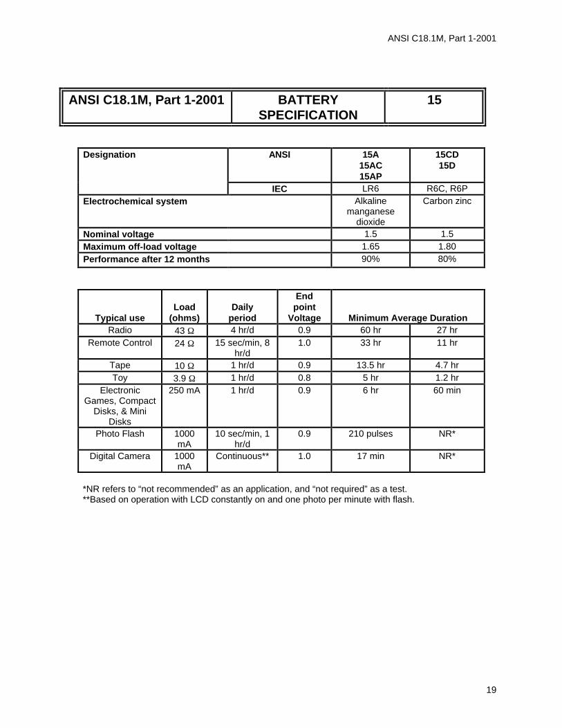
Designation ANSI 15A 15AC 15AP
15CD 15D
IEC LR6 R6C, R6P Electrochemical system Alkaline
manganese dioxide
Carbon zinc
Nominal voltage 1.5 1.5 Maximum off-load voltage 1.65 1.80 Performance after 12 months 90% 80%
Typical use
Load
(ohms)
Daily
period
End point
Voltage
Minimum Average Duration Radio 43 Ω 4 hr/d 0.9 60 hr 27 hr
Remote Control 24 Ω 15 sec/min, 8 hr/d
1.0 33 hr 11 hr
Tape 10 Ω 1 hr/d 0.9 13.5 hr 4.7 hr Toy 3.9 Ω 1 hr/d 0.8 5 hr 1.2 hr
Electronic Games, Compact
Disks, & Mini Disks
250 mA 1 hr/d 0.9 6 hr 60 min
Photo Flash 1000 mA
10 sec/min, 1 hr/d
0.9 210 pulses NR*
Digital Camera 1000 mA
Continuous** 1.0 17 min NR*
*NR refers to “not recommended” as an application, and “not required” as a test. **Based on operation with LCD constantly on and one photo per minute with flash.

ANSI C18.1M, Part 1-2001
20
ANSI C18.1M, Part 1-2001 BATTERY SPECIFICATION
24
0.25 M P F
A
B
CP
(+)
(-)
G
NOTES
1. Terminals: Cap and base 2. B (Min) of 43.5 mm [1.713 in] is under
consideration. 3. G (Min) of 0.85 mm [0.033 in] is under
consideration.
Small battery
Dimensions Millimeters Inches A (Max) 44.5 1.752 B (Min) 43.3 1.705 C (Min) 4.3 0.169 F (Max) 3.8 0.150 G (Min) 0.8 0.031 ∅ (Max) 10.5 0.413 ∅ (Min) 9.5 0.374
ANSI C18.1M, Part 1-2001
21
ANSI C18.1M, Part 1-2001 BATTERY SPECIFICATION
24
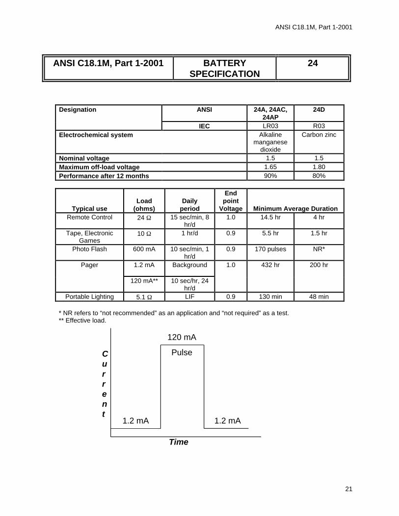
Designation ANSI 24A, 24AC, 24AP
24D
IEC LR03 R03 Electrochemical system Alkaline
manganese dioxide
Carbon zinc
Nominal voltage 1.5 1.5 Maximum off-load voltage 1.65 1.80 Performance after 12 months 90% 80%
Typical use
Load
(ohms)
Daily
period
End point
Voltage
Minimum Average Duration Remote Control 24 Ω 15 sec/min, 8
hr/d 1.0 14.5 hr 4 hr
Tape, Electronic Games
10 Ω 1 hr/d 0.9 5.5 hr 1.5 hr
Photo Flash 600 mA 10 sec/min, 1 hr/d
0.9 170 pulses NR*
1.2 mA
Background
Pager
120 mA** 10 sec/hr, 24 hr/d
1.0 432 hr 200 hr
Portable Lighting 5.1 Ω LIF 0.9 130 min 48 min
* NR refers to “not recommended” as an application and “not required” as a test. ** Effective load.
Current
Time
1.2 mA 1.2 mA
Pulse
120 mA

ANSI C18.1M, Part 1-2001
22
ANSI C18.1M, Part 1-2001 BATTERY SPECIFICATION
25
AB
G
(+)
(-)
C
F
NOTE—Terminals: Cap and base Small battery
Designation ANSI 25A IEC LR8D425 Electrochemical system Alkaline
manganese dioxide Nominal voltage 1.5 Maximum off-load voltage 1.65 Performance after 12 months 90%
Typical use
Load
(ohms)
Daily
period
End point
Voltage
Minimum Average
Duration Flashlight 5.1 5 min/d 0.9 78 min
Rating 75 1 hr/d 0.9 27 hr
Dimensions Millimeters Inches A (Max) 42.5 1.673 B (Min) 41.5 1.634 C (Min) 4.3 0.169 F (Max) 3.8 0.150 G (Min) 0.7 0.028 ∅ (Max) 8.3 0.327 ∅ (Min) 7.7 0.303

ANSI C18.1M, Part 1-2001
23
ANSI C18.1M, Part 1-2001 BATTERY SPECIFICATION
903
(-) (+)
36.131.0
103.2100.0
95.794.8 185.7
181.0
149.2145.4
163.5158.8
Millimeters Inches Millimeters Inches Millimeters Inches 31.0 1.220 100.0 3.937 158.8 6.252 36.1 1.421 103.2 4.063 163.5 6.437 94.8 3.732 145.4 5.724 181.0 7.126 95.7 3.768 149.2 5.874 185.7 7.311
NOTE—Terminals: No. 8-32 terminal posts with knurl nuts. See 1.4.3.5.
Designation ANSI 903 IEC --- Electrochemical system Carbon zinc Nominal voltage 7.5 Maximum off-load voltage 9.0 Performance after 12 months 80%
Typical use
Load
(ohms)
Daily
period
End point
Voltage
Minimum average duration Portable lighting
2.7 30 min/hr, 8 hr/d
4.5 4.5 hr

ANSI C18.1M, Part 1-2001
24
ANSI C18.1M, Part 1-2001 BATTERY SPECIFICATION
904
(-) (+)
103.2100.0
149.9145.4
163.5158.8
217.9214.7
148.6143.5
NOTE—Terminals: No. 8-32 terminal posts with knurl nuts. See 1.4.3.5.
Designation ANSI 904 IEC --- Electrochemical system Carbon zinc Nominal voltage 9.0 Maximum off-load voltage 10.8 Performance after 12 months 80%
Typical use
Load
(ohms)
Daily
period
End point
Voltage
Minimum average duration
Portable lighting
3.3 30 min/hr, 8 hr/d
5.4 4.5 hr
Millimeters Inches Millimeters Inches 100.0 3.937 149.9 5.902 103.2 4.063 158.8 6.252 143.5 5.650 163.5 6.437 145.4 5.724 214.7 8.453 148.6 5.850 217.9 8.579
ANSI C18.1M, Part 1-2001
25
ANSI C18.1M, Part 1-2001 BATTERY SPECIFICATION
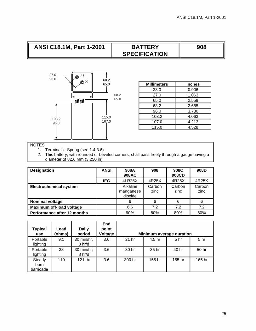
908
(+)
(-)
27.023.0
103.296.0
115.0107.0
68.265.0
68.265.0
NOTES
1. Terminals: Spring (see 1.4.3.6) 2. This battery, with rounded or beveled corners, shall pass freely through a gauge having a
diameter of 82.6 mm (3.250 in).
Designation ANSI 908A 908AC
908 908C 908CD
908D
IEC 4LR25X 4R25X 4R25X 4R25X Electrochemical system Alkaline
manganese dioxide
Carbon zinc
Carbon zinc
Carbon zinc
Nominal voltage 6 6 6 6 Maximum off-load voltage 6.6 7.2 7.2 7.2 Performance after 12 months 90% 80% 80% 80%
Typical use
Load
(ohms)
Daily
period
End point
Voltage
Minimum average duration Portable lighting
9.1 30 min/hr, 8 hr/d
3.6
21 hr
4.5 hr
5 hr
5 hr
Portable lighting
33 30 min/hr, 8 hr/d
3.6 80 hr
35 hr 40 hr
50 hr
Steady burn
barricade
110 12 hr/d 3.6 300 hr
155 hr 155 hr
165 hr
Millimeters Inches 23.0 0.906 27.0 1.063 65.0 2.559 68.2 2.685 96.0 3.780 103.2 4.063 107.0 4.213 115.0 4.528

ANSI C18.1M, Part 1-2001
26
ANSI C18.1M, Part 1-2001 BATTERY SPECIFICATION
910
F
AB
C
(+)
(-)
0.25 M P
P
G
NOTE—Terminals: Cap and base Small battery
Designation ANSI 910A IEC LR1 Electrochemical system Alkaline
manganese dioxide
Nominal voltage 1.5 Maximum off-load voltage 1.65 Performance after 12 months 90%
Typical
use
Load
(ohms)
Daily
period
End point
Voltage
Minimum average duration Portable Lighting
5.1 5 min/day
0.9 100 min
Pager 10 Ω--5 sec/hr, then 3 kΩ --3,595 sec/hr
0.9 888 hr
Dimension Millimeters Inches A (Max) 30.2 1.189 B (Min) 29.1 1.146 C (Min) 5.0 0.197 F (Max) 4.7 0.185 G (Min) 0.5 0.020 ∅ (Max) 12.0 0.472 ∅ (Min) 10.9 0.429

ANSI C18.1M, Part 1-2001
27
ANSI C18.1M, Part 1-2001 BATTERY SPECIFICATION
915
(+)(-)
23.421.8
68.265.0
68.265.0
112.0107.0
103.296.0
Millimeters Inches Millimeters Inches
21.8 0.858 96.0 3.780 23.4 0.921 103.2 4.063 65.0 2.559 107.0 4.213 68.2 2.685 112.0 4.409
NOTES 1. Terminals: No. 8-32 terminal post with knurl nuts. See 1.4.3.5. 2. This battery, with rounded or beveled corners, shall pass freely through a gauge having a
diameter of 82.6 mm (3.250 in).
Designation
ANSI 915A 915AC
915 915C 915D
IEC 4LR25Y 4R25Y Electrochemical system Alkaline
manganese dioxide
Carbon zinc
Nominal voltage 6 6 Maximum off-load voltage 6.6 7.2 Performance after 12 months 90% 80%
Typical
use
Load
(ohms)
Daily
period
End point
Voltage
Minimum average duration Portable lighting
9.1 30 min/hr, 8 hr/d
3.6 21 hr 4.5 hr
Portable lighting
33 30 min/hr, 8 hr/d
3.6 80 hr 35 hr

ANSI C18.1M, Part 1-2001
28
ANSI C18.1M, Part 1-2001 BATTERY SPECIFICATION
918
(-) (+)
77.075.4
136.5132.5
73.069.0
114.0109.5
127.0 Max
NOTE—Terminals: No. 8-32 terminal post with knurl nuts. See 1.4.3.5.
Designation ANSI 918A
918AC 918 918D
IEC 4LR25-2 4R25-2 4R25-2 Electrochemical system Alkaline
manganese dioxide
Carbon zinc
Carbon zinc
Nominal voltage 6 6 6 Maximum off-load voltage 6.6 7.2 7.2 Performance after 12 months 90% 80% 80%
Typical use
Load
(ohms)
Daily
period
End point
Voltage
Minimum average duration Portable lighting
9.1 30 min/hr, 8 hr/d
3.6 60 hr 15 hr 20 hr
Millimeters Inches Millimeters Inches 69.0 2.717 114.0 4.488 73.0 2.874 127.0 5.000 75.4 2.969 132.5 5.217 77.0 3.031 136.5 5.374 109.5 4.311

ANSI C18.1M, Part 1-2001
29
ANSI C18.1M, Part 1-2001 BATTERY SPECIFICATION
926
(-) (+)
86.584.9
136.5132.5
48.446.8
73.069.0
112.7109.5
125.4122.2
Millimeters Inches Millimeters Inches Millimeters Inches 46.8 1.843 86.5 3.406 122.2 4.811 48.4 1.906 84.9 3.343 125.4 4.937 69.0 2.717 109.5 4.311 132.5 5.217 73.0 2.874 112.7 4.437 136.5 5.374
NOTE—Terminals: No. 8-32 terminal posts with knurl nuts. See 1.4.3.5.
Designation ANSI 926AC 926 IEC --- --- Electrochemical system Alkaline
manganese dioxide
Carbon zinc
Nominal voltage 12 12 Maximum off-load voltage 13.2 14.4 Performance after 12 months 90% 80%
Typical use
Load
(ohms)
Daily
period
End point
Voltage
Minimum average duration Portable lighting
18 30 min/hr, 8 hr/d
7.2 40 hr 7 hr

ANSI C18.1M, Part 1-2001
30
ANSI C18.1M, Part 1-2001 BATTERY SPECIFICATION
1107, 1131, 1166, 1184, 7003
AB
(-)
(+)
NOTE—Terminals: Cap and case Small battery
Designation ANSI 1166A 1131SO 1107SOP
1184SO 7003ZD
IEC LR44 SR44 SR44 PR44 Electrochemical system
Alkaline manganese
dioxide
Silver oxide Silver oxide Zinc air
Nominal voltage 1.5 1.5 1.5 1.4 Maximum off-load voltage
1.65 1.63 1.63 1.68
Performance after 12 months
90% 90% 90% 95%
Typical use
Load
(ohms)
Daily
period
End point
Voltage
Minimum average duration Hearing
Aid 620 12 hr 1.1 --- 63 hr --- 189 hr
Hearing Aid
620 12 hr 1.0 --- 65 hr --- 195 hr
Rating 6.8 k 24 hr 1.2 500 hr 750 hr 650 hr ---
Dimensions Millimeters Inches A (Max) 5.4 0.213 B (Min) 5.0 0.197 ∅ (Max) 11.6 0.457 ∅ (Min) 11.25 0.443

ANSI C18.1M, Part 1-2001
31
ANSI C18.1M, Part 1-2001 BATTERY SPECIFICATION
1132, 1133
AB
(-)
(+)
NOTES - Terminals: Cap and case Small battery
Designation ANSI 1132SO 1133SO IEC SR43 SR43 Electrochemical system Silver oxide
Nominal voltage 1.5 1.5 Maximum off-load voltage 1.63 1.63 Performance after 12 months 90% 90%
Typical use
Load
(ohms)
Daily
period
End point
Voltage
Minimum average duration Rating 10 k 24 hr 1.2 620 hr 620 hr
Dimensions Millimeters Inches A (Max) 4.2 0.165 B (Min) 3.8 0.150 ∅ (Max) 11.6 0.457 ∅ (Min) 11.25 0.443

ANSI C18.1M, Part 1-2001
32
ANSI C18.1M, Part 1-2001 BATTERY SPECIFICATION
1134, 1135, 1179, 7002
AB
(-)
(+)
NOTE—Terminals: Cap and case Small battery
Designation ANSI 1134SO 1135SO 1179SO 7002ZD IEC SR41 SR41 SR41 PR41 Electrochemical system Silver oxide Zinc air Nominal voltage 1.5 1.5 1.5 1.4 Maximum off-load voltage 1.63 1.63 1.63 1.68 Performance after 12 months 90% 90% 90% 95%
Typical use
Load
(ohms)
Daily
period
End point
Voltage
Minimum average duration Hearing
aid 1.5 k 12 hr 1.1 --- --- 34 hr 97 hr
Hearing aid
1.5 k 12 hr 1.0 --- --- 35 hr 100 hr
Rating 22 k 24 hr 1.2 450 hr 450 hr --- ---
Dimensions Millimeters Inches A (Max) 3.6 0.142 B (Min) 3.25 0.128 ∅ (Max) 7.9 0.311 ∅ (Min) 7.55 0.297

ANSI C18.1M, Part 1-2001
33
ANSI C18.1M, Part 1-2001 BATTERY SPECIFICATION
1136, 1137, 1181, 7000
AB
(-)
(+)
NOTE—Terminals: Cap and case Small battery
Designation ANSI 1136SO 1137SO 1181SO 7000ZD IEC SR48 SR48 SR48 PR48 Electrochemical system Silver oxide Zinc air Nominal voltage 1.5 1.5 1.5 1.4 Maximum off-load voltage 1.63 1.63 1.63 1.68 Performance after 12 months 90% 90% 90% 95%
Typical use
Load
(ohms)
Daily
period
End point
Voltage
Minimum average duration Hearing
aid 1.5 k 12 hr 1.1 --- --- 58 hr 189 hr
Hearing aid
1.5 k 12 hr 1.0 --- --- 60 hr 195 hr
Rating 15 k 24 hr 1.2 580 hr 720 hr --- ---
Dimensions Millimeters Inches A (Max) 5.4 0.213 B (Min) 5.0 0.197 ∅ (Max) 7.9 0.311 ∅ (Min) 7.55 0.297

ANSI C18.1M, Part 1-2001
34
ANSI C18.1M, Part 1-2001 BATTERY SPECIFICATION
1138
AB
(-)
(+)
NOTE—Terminals: Cap and case Small battery
Designation ANSI 1138SO IEC SR54 Electrochemical system Silver oxide Nominal voltage 1.5 Maximum off-load voltage 1.63 Performance after 12 months 90%
Typical use
Load
(ohms)
Daily
period
End point
Voltage
Minimum average duration Rating 15 k 24 hr 1.2 720 hr
Dimensions Millimeters Inches A (Max) 3.05 0.120 B (Min) 2.75 0.108 ∅ (Max) 11.6 0.457 ∅ (Min) 11.25 0.443

ANSI C18.1M, Part 1-2001
35
ANSI C18.1M, Part 1-2001 BATTERY SPECIFICATION
1139
AB
(-)
(+)
NOTE—Terminals: Cap and case Small battery
Designation ANSI 1139SO IEC SR42 Electrochemical system Silver oxide Nominal voltage 1.5 Maximum off-load voltage 1.63 Performance after 12 months 90%
Typical use
Load
(ohms)
Daily
period
End point
Voltage
Minimum average duration Rating 15 k 24 hr 1.2 750 hr
Dimensions Millimeters Inches A (Max) 3.6 0.142 B (Min) 3.3 0.130 ∅ (Max) 11.6 0.457 ∅ (Min) 11.25 0.443

ANSI C18.1M, Part 1-2001
36
ANSI C18.1M, Part 1-2001 BATTERY SPECIFICATION
1158
AB
(-)
(+)
NOTE—Terminals: Cap and case Small battery
Designation ANSI 1158SO IEC SR58 Electrochemical system Silver oxide Nominal voltage 1.5 Maximum off-load voltage 1.63 Performance after 12 months 90%
Typical use
Load
(ohms)
Daily
period
End point
Voltage
Minimum average duration Rating 47 k 24 hr 1.2 518 hr
Dimensions Millimeters Inches A (Max) 2.1 0.083 B (Min) 1.85 0.073 ∅ (Max) 7.9 0.311 ∅ (Min) 7.55 0.297

ANSI C18.1M, Part 1-2001
37
ANSI C18.1M, Part 1-2001 BATTERY SPECIFICATION
1160, 1170
AB
(-)
(+)
NOTE—Terminals: Cap and case Small battery
Designation ANSI 1160SO 1170SO IEC SR55 SR55 Electrochemical system Silver oxide Silver oxide Nominal voltage 1.5 1.5 Maximum off-load voltage 1.63 1.63 Performance after 12 months 90% 90%
Typical use
Load
(ohms)
Daily
period
End point
Voltage
Minimum average duration Rating 22 k 24 hr 1.2 450 hr 450 hr
Dimensions Millimeters Inches A (Max) 2.1 0.083 B (Min) 1.85 0.073
∅ (Max) 11.6 0.457 ∅ (Min) 11.25 0.443

ANSI C18.1M, Part 1-2001
38
ANSI C18.1M, Part 1-2001 BATTERY SPECIFICATION
1162, 1165
AB
(-)
(+)
NOTE—Terminals: Cap and case Small battery
Dimensions Millimeters Inches A (Max) 2.7 0.106 B (Min) 2.4 0.094 ∅ (Max) 9.5 0.374 ∅ (Min) 9.15 0.360
Designation ANSI 1162SO 1165SO IEC SR57 SR57 Electrochemical system Silver oxide Silver oxide Nominal voltage 1.5 1.5 Maximum off-load voltage 1.63 1.63 Performance after 12 months 90% 90%
Typical
use
Load
(ohms)
Daily
period
End point
Voltage
Minimum average duration Rating 22 k 24 hr 1.2 500 hr 650 hr

ANSI C18.1M, Part 1-2001
39
ANSI C18.1M, Part 1-2001 BATTERY SPECIFICATION
1163, 1164
AB
(-)
(+)
NOTE—Terminals: Cap and case Small battery
Designation ANSI 1163SO 1164SO IEC SR59 SR59 Electrochemical system Silver oxide Silver oxide Nominal voltage 1.5 1.5 Maximum off-load voltage 1.63 1.63 Performance after 12 months 90% 90%
Typical use
Load
(ohms)
Daily
period
End point
Voltage
Minimum average duration Rating 33 k 24 hr 1.2 600 hr 600 hr
Dimensions Millimeters Inches A (Max) 2.6 0.103 B (Min) 2.3 0.091 ∅ (Max) 7.9 0.311 ∅ (Min) 7.55 0.297

ANSI C18.1M, Part 1-2001
40
ANSI C18.1M, Part 1-2001 BATTERY SPECIFICATION
1175
AB
(-)
(+)
NOTE—Terminals: Cap and case Small battery
Designation ANSI 1175SO IEC SR60 Electrochemical system Silver oxide Nominal voltage 1.5 Maximum off-load voltage 1.63 Performance after 12 months 90%
Typical use
Load
(ohms)
Daily
period
End point
Voltage
Minimum average duration Rating 68 k 24 hr 1.2 685 hr
Dimensions Millimeters Inches A (Max) 2.15 0.085 B (Min) 1.9 0.075 ∅ (Max) 6.8 0.268 ∅ (Min) 6.5 0.256

ANSI C18.1M, Part 1-2001
41
ANSI C18.1M, Part 1-2001 BATTERY SPECIFICATION
1176, 1196
AB
(-)
(+)
Dimensions Millimeters Inches A (Max) 2.6 0.102 B (Min) 2.4 0.094 ∅ (Max) 6.8 0.268
∅ (Min) 6.6 0.260
NOTE—Terminals: Cap and case Small battery
Designation ANSI 1176SO 1196SO IEC SR66 SR66 Electrochemical system Silver oxide Silver oxide Nominal voltage 1.5 1.5 Maximum off-load voltage 1.63 1.63 Performance after 12 months 90% 90%
Typical use
Load
(ohms)
Daily
period
End point
Voltage
Minimum Average Duration Rating 47 k 24 hr 1.2 680 hr 680 hr

ANSI C18.1M, Part 1-2001
42
ANSI C18.1M, Part 1-2001 BATTERY SPECIFICATION
1177
AB
(-)
(+)
NOTE—Terminals: Cap and case Small battery
Designation ANSI 1177SO IEC --- Electrochemical system Silver oxide Nominal voltage 1.5 Maximum off-load voltage 1.63 Performance after 12 months 90%
Typical use
Load
(ohms)
Daily
period
End point
Voltage
Minimum average duration Rating 30 k 24 hr 1.2 585 hr
Dimensions Millimeters Inches A (Max) 1.6 0.063 B (Min) 1.35 0.053 ∅ (Max) 11.6 0.457 ∅ (Min) 11.25 0.443

ANSI C18.1M, Part 1-2001
43
ANSI C18.1M, Part 1-2001 BATTERY SPECIFICATION
1191, 7012
AB
(-)
(+)
NOTE—Terminals: Cap and case Small battery
Designation ANSI 1191SO 7012Z IEC SR63 --- Electrochemical system Silver oxide Zinc air Nominal voltage 1.5 1.4 Maximum off-load voltage 1.63 1.68 Performance after 12 months 90% 95%
Typical use
Load
(ohms)
Daily
period
End point
Voltage
Minimum average duration Hearing
aid 6.5 k 12 hr 1.1 --- 135 hr
Hearing aid
6.5 k 12 hr 1.0 --- 140 hr
Rating 68 k 24 hr 1.2 500 hr ---
Dimensions Millimeters Inches A (Max) 2.15 0.085 B (Min) 1.9 0.075 ∅ (Max) 5.8 0.228 ∅ (Min) 5.55 0.219

ANSI C18.1M, Part 1-2001
44
ANSI C18.1M, Part 1-2001 BATTERY SPECIFICATION
1406, 1414
AB
(-)
(+)
NOTE—Terminals: Flat contact Small battery
Designation ANSI 1406SOP 1414A IEC 4SR44 4LR44 Electrochemical system Silver oxide Alkaline
manganese dioxide
Nominal voltage 6 6 Maximum off-load voltage 6.52 6.6 Performance after 12 months 90% 90%
Typical use
Load
(ohms)
Daily
period
End point
Voltage
Minimum average duration Rating 27 k 24 hr 3.6 620 hr 620 hr
Dimensions Millimeters Inches A (Max) 25.2 0.992 B (Min) 23.9 0.941 ∅ (Max) 13.0 0.512 ∅ (Min) 12.0 0.472

ANSI C18.1M, Part 1-2001
45
ANSI C18.1M, Part 1-2001 BATTERY SPECIFICATION
1412
45°
(+) (-)
35.635.0
48.547.0
9.28.7
Designation ANSI 1412AP IEC 4LR61 Electrochemical system Alkaline
manganese dioxide
Nominal voltage 6 Maximum off-load voltage 6.6 Performance after 12 months 90%
Typical use
Load
(ohms)
Daily
period
End point
Voltage
Minimum average duration Electronic equipment
330 24 hr 3.6 25 hr
Rating 6.8 k 24 hr 3.6 650 hr
Millimeters Inches 8.7 0.342 9.2 0.362 35.0 1.378 35.6 1.402 47.0 1.850 48.5 1.909

ANSI C18.1M, Part 1-2001
46
ANSI C18.1M, Part 1-2001 BATTERY SPECIFICATION
1604, 7004
NOTE—Terminals: Snap
Designation ANSI 1604A 1604AC
1604 1604C
1604D 1604CD
7004Z
IEC 6LR61 6F22 6F22 --- Electrochemical system Alkaline
manganese dioxide
Carbon zinc Zinc air
Nominal voltage 9 9 9 8.4 Maximum off-load voltage 9.9 10.8 10.8 10.8 Performance after 12 months 90% 80% 80% 95%
Typical use
Load
(ohms)
Daily
period
End point
Voltage
Minimum average duration Toy 270 1 hr/d 5.4 14 hr 7 hr 9 hr ---
Radio 620 2 hr/d 5.4 38 hr 23 hr 24 hr --- 43 k
Background
Smoke Detector 620 pulse 1 sec/hr,
24 hr/d
7.5 30 days --- 15 days ---
NOTE—The pulse load of 620 Ω alone shall be applied across the battery for 1 s/h. It is the effective load. It is not added in series or parallel to the 43 kΩ background load.
(+)(-)
12.9512.45
17.515.5
46.4Max
48.546.5
26.524.5
Millimeters Inches 12.45 0.490 12.95 0.510 15.5 0.610 17.5 0.689 24.5 0.965 26.5 1.043 46.4 1.827 46.5 1.831 48.5 1.909

ANSI C18.1M, Part 1-2001
47
ANSI C18.1M, Part 1-2001 BATTERY SPECIFICATION
7005
(-)
(+)
AB
NOTE—Terminals: Cap and case Small battery
Designation ANSI 7005ZD IEC PR70 Electrochemical system Zinc air Nominal voltage 1.4 Maximum off-load voltage 1.68 Performance after 12 months 95%
Typical use
Load
(ohms)
Daily
period
End point
Voltage
Minimum average duration Hearing
aid 3 k 12 hr 1.1 111 hr
Hearing aid
3 k 12 hr 1.0 115 hr
Dimensions Millimeters Inches A (Max) 3.6 0.142 B (Min) 3.3 0.130 ∅ (Max) 5.8 0.228 ∅ (Min) 5.6 0.220

ANSI C18.1M, Part 1-2001
48
ANSI C18.1M, Part 1-2001 BATTERY SPECIFICATION
7007
(-)
(+)
AB
NOTE—Terminals: Cap and case Small battery
Designation ANSI 7007Z IEC --- Electrochemical system Zinc air Nominal voltage 1.4 Maximum off-load voltage 1.68 Performance after 12 months 95%
Typical use
Load
(ohms)
Daily
period
End point
Voltage
Minimum average duration Pager 330 24 hr 1.0 230 hr
Dimensions Millimeters Inches A (Max) 6.2 0.244 B (Min) 5.8 0.228 ∅ (Max) 15.6 0.614 ∅ (Min) 15.4 0.606

ANSI C18.1M, Part 1-2001
49
Annex A (informative)
Methods of determining load and test conditions
A.1 Application tests
a) The discharge load is calculated from the average current and average operating voltage of the most popular representative equipment.
b) The functional end point voltage and the discharge load value are obtained from the data on all the
equipment measured.
c) The median class defines the discharge load value and the end point voltage to be used for the discharge test.
d) If the data are concentrated in two or more widely separated groups, more than one test may be
required.
e) The daily discharge period should reflect typical consumer use.
f) In order to minimize the proliferation of application tests, the tests specified should be those accounting for 80% of the market by battery size with a limited number of tests.
g) Application tests should be used unless they require an excessive amount of time to run.
A.2 Capacity or rating tests For capacity/rating tests, the value of the discharge load shall be selected such that the service output approximates 30 days. When full capacity is not realized within the required time period, the service output may be extended to the shortest suitable duration thereafter by selecting a more appropriate discharge load.

ANSI C18.1M, Part 1-2001
50
This page intentionally left blank.

ANSI C18.1M, Part 1-2001
51
Annex B (informative)
Guidance for packaging, handling, storage, and transportation
B.1 Introduction The greatest satisfaction to the user of primary batteries results from a combination of good practices during manufacture, distribution, and use. The purpose of this code is to describe these good practices in general terms and, more specifically, to warn against procedures known from experience to be undesirable. It takes the form of advice to battery manufacturers, distributors, equipment designers, and users. B.2 Packing The packing should be adequate to avoid mechanical damage during transport, handling, and stacking. The materials and pack design should be chosen so as to prevent the development of unintentional electrical conduction, corrosion of the terminals, and ingress of moisture. B.3 Transport and handling Shock and vibration should be kept to a minimum. For instance, boxes should not be thrown off trucks, slammed into position, or piled so high as to overload battery containers below. Protection from inclement weather should be provided. B.4 Storage and stock rotation B.4.1 For normal storage, the temperature should be between +10° C and +25° C and never exceed +30° C. Batteries should therefore not be stored next to radiators or boilers nor in direct sunlight. Extremes of humidity (below 35% and above 95% relative humidity) for sustained periods should be avoided since they are detrimental to both batteries and packing. B.4.2 Although the storage life of batteries at room temperature is good, storage is improved at lower temperatures, provided special precautions are taken. The batteries should be enclosed in special protective packing (such as sealed plastic bags or variants) which should be retained to protect them from condensation during the time they are warming to ambient temperature. Also, accelerated warming is harmful. B.4.3 Batteries may be stored while fitted in equipment or packages if determined suitable by the battery manufacturer. B.4.4 Batteries should be shipped promptly after manufacture. In order to practice stock rotation (first-in, first-out), storage areas and displays should be properly designed and packs adequately marked. B.5 Display and sales points B.5.1 When batteries are unpacked, care should be taken to avoid physical damage and accidental discharge. B.5.2 The battery manufacturer should provide some information to assist the retailer in selecting the correct battery for the user’s application.

ANSI C18.1M, Part 1-2001
52
This page intentionally left blank.

ANSI C18.1M, Part 1-2001
53
Annex C (informative)
Reliability guidelines
C.1 Consumer/user In order to assure that batteries and appliances operate reliably, the following should be taken into consideration:
a) Since batteries are sensitive to high temperature, when storing them, keep them in a cool dry place.
b) Battery contacts need to be clean, both on the battery and in the appliance. c) Batteries should be removed from the appliance when not being used for long periods of time
(months). d) Choose the proper battery for the intended application. Follow the recommendations supplied with
the appliance. e) Never charge a battery unless the battery label specifically states that it is a rechargeable battery. f) Use the power cord supplied with the appliance since the use of other cords may result in the
batteries in the appliance being charged. C.2 The designer The following are considerations for the designer:
a) Choose the proper battery for the intended application. b) Never solder or weld to a battery without first contacting the manufacturer for advice. c) The choice of contact material and the type of contact mechanism will affect the reliability of the
appliance/device being designed. d) Pressure contacts require a special knowledge of contact materials, corrosion couples, connection
force, point connections, corrosion inhibitors, etc. e) Care should be taken to avoid battery damage during ultrasonic sealing. f) Once sample units are developed, high temperature and humidity tests should be performed to
test for contact integrity. g) Care should be taken to avoid battery damage during ultrasonic sealing. h) Battery compartment contacts should be designed to prevent reverse battery installation.

ANSI C18.1M, Part 1-2001
54
This page intentionally left blank.

ANSI C18.1M, Part 1-2001
55
Annex D (informative)
Bibliography
ANSI/IEEE 268, American National Standard metric practice IEC 60086-1, Primary batteries, Part 1: General IEC 60086-2, Primary batteries, Part 2: Specification sheets

ANSI C18.1M, Part 1-2001
56
This page intentionally left blank.


