Ambient Weather WS-50-C User Manual
66
Version 1.4 ©Copyright 2020, Ambient LLC. All Rights Reserved. Page 1 Ambient Weather WS-50-C Wi-Fi Smart Weather Station User Manual Table of Contents Contents 1. Introduction ................................................................................................................................................ 3 2. Warnings .................................................................................................................................................... 4 3. Quick Start Guide ....................................................................................................................................... 4 4. Parts ........................................................................................................................................................... 4 4.1 WiFi Display Console (included) ........................................................................................................ 4 4.2 Anemometer (optional) ...................................................................................................................... 5 4.3 Rain Gauge (optional) ........................................................................................................................ 6 5. Indoor / Outdoor Thermo-Hygrometer (optional) ......................................................................................... 7 5.1 Floating Pool, Spa and Pond Thermometer (optional) ......................................................................... 7 5.2 Temperature Probe (optional) ............................................................................................................. 8 5.3 Indoor Thermo-Hygrometer................................................................................................................ 8 6. Recommend Tools ...................................................................................................................................... 8 7. Sensor Assembly and Installation ................................................................................................................ 9 7.1 Anemometer ...................................................................................................................................... 9 7.1.1 Anemometer Assembly .................................................................................................................. 9 7.1.2 Anemometer Installation .............................................................................................................. 10 7.2 Rain Gauge ...................................................................................................................................... 12 7.2.1 Rain Gauge Assembly .................................................................................................................. 12 7.2.2 Rain Gauge Installation ................................................................................................................ 13 7.3 Thermo-Hygrometer (F007TH) ........................................................................................................ 14 7.3.1 Thermo-Hygrometer Assembly .................................................................................................... 14 7.3.2 Thermo-Hygrometer Installation .................................................................................................. 16 7.4 Floating Pool, Spa and Pond Thermometer (F007PF) ........................................................................ 17 7.4.1 Floating Pool, Spa and Pond Thermometer Assembly ................................................................... 17 7.4.2 Sensor Placement ......................................................................................................................... 22 7.5 Probed Thermometer (F007TP) ........................................................................................................ 23 7.5.1 Probed Thermometer Assembly.................................................................................................... 24 7.5.2 Probed Thermometer Installation .................................................................................................. 26 7.5.3 Refrigerator/Freezer Mounting ..................................................................................................... 26 7.5.4 Wall Mounting ............................................................................................................................. 27
Transcript of Ambient Weather WS-50-C User Manual

Version 1.4 ©Copyright 2020, Ambient LLC. All Rights Reserved. Page 1
Ambient Weather WS-50-C Wi-Fi Smart Weather Station User
Manual
Table of Contents
Contents
1. Introduction ................................................................................................................................................ 3
2. Warnings .................................................................................................................................................... 4
3. Quick Start Guide ....................................................................................................................................... 4
4. Parts ........................................................................................................................................................... 4
4.1 WiFi Display Console (included) ........................................................................................................ 4
4.2 Anemometer (optional) ...................................................................................................................... 5
4.3 Rain Gauge (optional) ........................................................................................................................ 6
5. Indoor / Outdoor Thermo-Hygrometer (optional) ......................................................................................... 7
5.1 Floating Pool, Spa and Pond Thermometer (optional) ......................................................................... 7
5.2 Temperature Probe (optional) ............................................................................................................. 8
5.3 Indoor Thermo-Hygrometer ................................................................................................................ 8
6. Recommend Tools ...................................................................................................................................... 8
7. Sensor Assembly and Installation ................................................................................................................ 9
7.1 Anemometer ...................................................................................................................................... 9
7.1.1 Anemometer Assembly .................................................................................................................. 9
7.1.2 Anemometer Installation .............................................................................................................. 10
7.2 Rain Gauge ...................................................................................................................................... 12
7.2.1 Rain Gauge Assembly .................................................................................................................. 12
7.2.2 Rain Gauge Installation ................................................................................................................ 13
7.3 Thermo-Hygrometer (F007TH) ........................................................................................................ 14
7.3.1 Thermo-Hygrometer Assembly .................................................................................................... 14
7.3.2 Thermo-Hygrometer Installation .................................................................................................. 16
7.4 Floating Pool, Spa and Pond Thermometer (F007PF) ........................................................................ 17
7.4.1 Floating Pool, Spa and Pond Thermometer Assembly ................................................................... 17
7.4.2 Sensor Placement ......................................................................................................................... 22
7.5 Probed Thermometer (F007TP) ........................................................................................................ 23
7.5.1 Probed Thermometer Assembly .................................................................................................... 24
7.5.2 Probed Thermometer Installation .................................................................................................. 26
7.5.3 Refrigerator/Freezer Mounting ..................................................................................................... 26
7.5.4 Wall Mounting ............................................................................................................................. 27

Version 1.4 ©Copyright 2020, Ambient LLC. All Rights Reserved. Page 2
7.6 Indoor Thermo-Hygrometer (FT012TH) ........................................................................................... 28
7.6.1 Indoor Thermo-Hygrometer Assembly ......................................................................................... 28
7.6.2 Display Features .......................................................................................................................... 30
7.6.3 Indoor Thermo-Hygrometer Sensor Operation .............................................................................. 31
7.6.4 Backlight Operation ..................................................................................................................... 32
7.6.5 Adjustment or Calibration ............................................................................................................ 32
7.6.6 Indoor Sensor Installation ............................................................................................................. 34
8. Weather Station Installation Guide and Limitations ................................................................................... 35
8.1 Pre-Installation Checkout ................................................................................................................. 36
8.2 Site Survey ....................................................................................................................................... 36
8.3 Best Practices for Wireless Communication ...................................................................................... 36
9. Display Console Set Up ............................................................................................................................ 37
9.1 Display Console Layout ................................................................................................................... 37
9.2 Display Power Up ............................................................................................................................ 38
9.3 Sensor Operation Verification........................................................................................................... 40
10. Console Operation ................................................................................................................................ 41
10.1 Quick Display Mode ........................................................................................................................ 41
10.2 Set or Program Mode ....................................................................................................................... 41
10.3 Channel Selection ............................................................................................................................ 42
10.4 Sensor Search Mode ......................................................................................................................... 43
10.5 View and Reset Min/Max Record ..................................................................................................... 43
10.6 Restore Factory Default .................................................................................................................... 44
10.7 Snooze Mode ................................................................................................................................... 44
10.8 Back light Mode ............................................................................................................................... 44
10.9 RF Signal Quality ............................................................................................................................. 44
10.10 Adjustment or Calibration ............................................................................................................ 45
10.10.1 Temperature Calibration........................................................................................................... 45
10.10.2 Humidity Calibration ............................................................................................................... 45
10.10.3 Absolute and Relative Barometer, Wind and Rain Calibration .................................................. 46
10.10.4 Clearing Rain Totals ................................................................................................................ 48
10.11 Alarm Mode ................................................................................................................................. 49
10.12 Alarm Operation .......................................................................................................................... 49
10.12.1 Viewing the High and Low Alarms .......................................................................................... 49
10.12.2 Setting the Alarms ................................................................................................................... 50
10.13 Alarm and Command Button Beeper ON/OFF Mode .................................................................... 51
10.14 WiFi Connection Status ................................................................................................................ 51
10.15 Time Server Sync Status .............................................................................................................. 51
11. WiFi and Internet Services .................................................................................................................... 51
11.1 Connect your Device to the Console's WiFi ...................................................................................... 52
11.2 Accessing the Console's Web Interface ............................................................................................. 54
12. AmbientWeather.net ............................................................................................................................. 57
12.1 Registering with AmbientWeather.net .............................................................................................. 57
12.2 Ambient Weather Apps .................................................................................................................... 58

Version 1.4 ©Copyright 2020, Ambient LLC. All Rights Reserved. Page 3
13. Third Party Public Websites.................................................................................................................. 59
14. AmbientWeather.net Works with and Community ................................................................................ 59
15. Updating Firmware ............................................................................................................................... 59
16. Glossary of Terms ................................................................................................................................ 60
17. Specifications ....................................................................................................................................... 61
17.1 Wireless Specifications .................................................................................................................... 61
17.2 Measurement Specifications ............................................................................................................. 61
17.3 Power Consumption ......................................................................................................................... 62
17.4 WiFi Specifications .......................................................................................................................... 62
18. Maintenance ......................................................................................................................................... 63
19. Accessories .......................................................................................................................................... 63
20. Liability Disclaimer .............................................................................................................................. 63
21. FCC Statement ..................................................................................................................................... 64
22. Warranty Information ........................................................................................................................... 64
23. California Prop 65 ................................................................................................................................ 65
Introduction
Thank you for your purchase of the WS-50-C Wi-Fi Smart Weather Station. The following user guide
provides step by step instructions for installation, operation, and troubleshooting. To download the latest
full-sized manual and additional troubleshooting tips, please visit:
https://help.ambientweather.net/product/ws-50
The WS-50-C is a Wi-Fi connected device that receives sensor data from a variety of sensors, displays and
configures this data, and sends it to your Wi-Fi router and the Internet.
The following items are may be packaged or sold separately with the WS-50-C:
Item Measurements Sensors
Supported
Comments
WS-50-C Indoor Temperature,
Humidity and Barometric
Pressure
-- Included
WS-12-ANEMOMETER Wind Speed and Wind
Direction
1 Optional
WS-12-RAIN Precipitation 1 Optional
F007TH Indoor or Outdoor
Temperature and
Humidity
8 Optional 8 Channel Sensor. Mix and
match with other 8 channel sensors.
F007PF Floating Pool, Spa and
Pond Thermometer
8 Optional 8 Channel Sensor. Mix and
match with other 8 channel sensors.
F007TP Indoor or Outdoor 8 Optional 8 Channel Sensor. Mix and

Version 1.4 ©Copyright 2020, Ambient LLC. All Rights Reserved. Page 4
Item Measurements Sensors
Supported
Comments
Temperature Probe match with other 8 channel sensors.
FT012TH Indoor Temperature and
Humidity
8 Optional 8 Channel Sensor. Mix and
match with other 8 channel sensors.
Figure 1
Warnings
Warning: Any metal object may attract a lightning strike, including your weather station mounting
pole. Never install the weather station in a storm.
Warning: Installing your weather station in a high location may result in injury or death. Perform as
much of the initial check out and operation.
Quick Start Guide
Step Description Section
1 Assemble and power up the sensors 6
2 Power up the display console and synchronize with wind sensor, rain
sensor and other sensor(s)
8.2
3 Install the sensors 6
5 Calibrate the relative or sea-level pressure (barometer) 9.10.3
6 Clear any total rain that may have accumulated during the set up. 9.10.4
7 Connect the console to Wi-Fi 10
8 Register at AmbientWeather.net 11
Parts
Wi-Fi Display Console (included)
QTY Item Image
1 WS-50-C
Display Console with Wi-Fi
Frame Dimensions (LxHxW): 6 x 3.25 x 1
in
LCD Dimensions (LxW): 4.5 x 2.5"

Version 1.4 ©Copyright 2020, Ambient LLC. All Rights Reserved. Page 5
QTY Item Image
1 Power Adapter
1 User Manual
Figure 2
Anemometer (optional)
QTY Item Image
1 WS-12-ANEMOMETER
Dimensions: 3 ¼ x 6 x 8 ½”
1 Pole
Dimensions: 12 x 1½ x 1”
1 Pole Mounting Bracket (with pole insert)
Dimensions: 3 x 4 x 1 ½”
1 Anemometer Mounting Bracket Back
Plate (pole mount)
Dimensions: 3 x 3 x 1”
4 Pole mounting nuts (M5) / bolts (∅5)

Version 1.4 ©Copyright 2020, Ambient LLC. All Rights Reserved. Page 6
QTY Item Image
4 Tapping screws
2 Pole mounting nuts (M3) / bolts (∅3)
Figure 3
Rain Gauge (optional)
QTY Item Image
1 WS-12-RAIN
Rain Gauge
Dimensions: 8 1/4" x 7 3/4" x 5" (5"
diameter)
1 Rain Gauge Filter
Dimensions: 2.48 x 2.48 x 1.1in
2 Pole mounting U-bolt / nuts (M5)
Figure 4
If sold separate from the anemometer (only one pole assembly is required per system), the following
parts are included:
QTY Item Image
1 Pole
Dimensions: 12 x 1½ x 1”

Version 1.4 ©Copyright 2020, Ambient LLC. All Rights Reserved. Page 7
QTY Item Image
1 Pole Mounting Bracket (with pole insert)
Dimensions: 3 x 4 x 1 ½”
1 Anemometer Mounting Bracket Back
Plate (pole mount)
Dimensions: 3 x 3 x 1”
4 Pole mounting nuts (M5) / bolts (∅5)
4 Tapping screws
2 Pole mounting nuts (M3) / bolts (∅3)
Figure 5
Indoor / Outdoor Thermo-Hygrometer (optional)
Item Image
F007TH
Thermo-hygrometer transmitter
Dimensions (LxHxW): 4.5 x 2.0 x 0.75in
Figure 6
Floating Pool, Spa and Pond Thermometer (optional)
Item Image

Version 1.4 ©Copyright 2020, Ambient LLC. All Rights Reserved. Page 8
Item Image
F007PF
Floating Pool, Spa and Pond Thermometer
Dimensions (LxWxH): 8.5" x 4.2" x 3.7"
Figure 7
Temperature Probe (optional)
Item Image
F007TP
Temperature Probe
Dimensions (LxHxW): 4.5 x 2.0 x 0.75in
Probe Length: 6 feet
Figure 8
Indoor Thermo-Hygrometer
Item Image
FT012TH
Indoor Thermo-hygrometer transmitter
Dimensions (LxHxW): 4.3” x 2.5” x 0.65”
Figure 9
Recommend Tools
Phillips Precision screwdriver Size: PH0 and PH2
Compass or GPS (for wind direction calibration)
Adjustable Wrench

Version 1.4 ©Copyright 2020, Ambient LLC. All Rights Reserved. Page 9
Hammer and nail for hanging remote thermo-hygrometer transmitter.
Sensor Assembly and Installation
Anemometer
Anemometer Assembly
The anemometer assembly consists of the wind cups, wind vane, solar panel, bubble level, sensor mounting
bracket and mounting foot. The solar panel provides power to the anemometer when the sun is out, and the
batteries provide power at night (the solar panel does not charge the batteries).
Figure 10
Locate the battery door on the anemometer transmitter, push and open the battery compartment, as shown in
Figure 11.

Version 1.4 ©Copyright 2020, Ambient LLC. All Rights Reserved. Page 10
Figure 11
Insert four batteries into the battery compartment, then press the reset button, as shown in Figure 12.
Note: Use high quality alkaline batteries, which have an operational temperature range of -4 to 140 °F.
Use Energizer e2 Lithium batteries for low temperature installation, which have an operational temperature
range of -40 to 140 °F. Do not use rechargeable batteries. They have a lower operating voltage and discharge
faster than non-rechargeable batteries and will result in short transmission ranges.
Figure 12
Anemometer Installation
Note: Do not install the anemometer until it is paired and operationally confirmed with the display
console.
Prior to installation, you will need to calibrate the wind direction. There is a “S” indicator on the wind vane
that indicates South, as shown in Figure 13. Align this “S” marker in the direction of South.

Version 1.4 ©Copyright 2020, Ambient LLC. All Rights Reserved. Page 11
Figure 13
Fasten the wind transmitter to mounting pole brackets with foot-mounting, two ∅3 bolts and M3 nuts, as
shown in Figure 14.
Figure 14
Tighten the included mounting pole to your mounting pole (purchased separately) with the four ∅5 Bolts and
M5 Nuts assembly, or fix on the wall with four tapping screws, as shown in Figure 15.

Version 1.4 ©Copyright 2020, Ambient LLC. All Rights Reserved. Page 12
Figure 15
Rain Gauge
Rain Gauge Assembly
The rain gauge consists of the rain gauge funnel, base, and drawer filter, as shown in Figure 16.
Figure 16

Version 1.4 ©Copyright 2020, Ambient LLC. All Rights Reserved. Page 13
Rotate and detach the rain gauge funnel, as shown in Figure 17.
Figure 17
Locate the battery door on the rain gauge transmitter, pull out the battery compartment, as shown in Figure
18.
Figure 18
Rain Gauge Installation
Remove the rain gauge funnel from the base prior to installation by rotating the counterclockwise until the
tabs on the base and the funnel align, then pulling upwards.
Fasten the rain gauge to the mounting pole. Tighten the rain gauge to your mounting pole or bracket with
two U-bolts and four M5 nuts or fix on a horizontal surface with the four tapping screws.
Reattach the funnel by aligning the tabs on the funnel and base and rotate clockwise.
Figure 19

Version 1.4 ©Copyright 2020, Ambient LLC. All Rights Reserved. Page 14
Figure 20
Thermo-Hygrometer (F007TH)
Thermo-Hygrometer Assembly
Remove the battery door on the back of the sensor by removing the set screw, as shown in Figure 21.
Figure 21
BEFORE inserting the batteries, locate the dip switches on the inside cover of the lid of the

Version 1.4 ©Copyright 2020, Ambient LLC. All Rights Reserved. Page 15
transmitter.
Figure 22 displays all four switches in the OFF position (factory default setting).
Figure 22
Channel Number: The WS-50 supports up to eight transmitters. To set each channel number (the
default is Channel 1), change Dip Switches 1, 2 and 3, as referenced in Table 1.
Temperature Units of Measure: To change the transmitter display units of measure (°F vs. °C), change
Dip Switch 4, as referenced in Table 1.
DIP SWITCH FUNCTION
1 2 3 4
DOWN DOWN DOWN --- Channel 1(outdoor)
DOWN DOWN UP --- Channel 2
DOWN UP DOWN --- Channel 3
DOWN UP UP --- Channel 4
UP DOWN DOWN --- Channel 5
UP DOWN UP --- Channel 6
UP UP DOWN --- Channel 7
UP UP UP --- Channel 8
--- --- --- DOWN °F
--- --- --- UP °C
Table 1
Insert two AAA batteries.
After inserting the batteries, the remote sensor LED indicator will light for 4 seconds, and then
flash once per 60 seconds thereafter. Each time it flashes, the sensor is transmitting data.
Verify the correct channel number (CH) and temperature units of measure (°F vs. °C) are on the
display, as shown in Figure 23.

Version 1.4 ©Copyright 2020, Ambient LLC. All Rights Reserved. Page 16
Figure 23
(1) temperature
(2) temperature units (°F vs. °C)
(3) channel number
(4) relative humidity
Close the battery door. Make sure the gasket (around the battery compartment) is properly seated
in its trace prior to closing the door. Tighten the set screw.
Thermo-Hygrometer Installation
Note: If you place the sensor outside, it is recommended you mount it in a shaded area. A north facing
wall is preferred because it is in the shade most of the day. Direct sunlight and radiant heat sources will
result in inaccurate temperature readings. Although the sensor is water resistant, it is best to mount in a
well-protected area, such as under an eve. Use a screw or nail (not included) to affix the remote sensor to the
wall, as shown in Figure 24.
Figure 24

Version 1.4 ©Copyright 2020, Ambient LLC. All Rights Reserved. Page 17
Sensors placed is shade on the north side of the house will experience lower daily highs and higher daily
lows because of the radiant heat (and cooling) of the walls and structure around it. This is known as thermal
mass and has a time averaging affect (just like the temperature of your pool will respond faster than a lake).
Optional Sensor Radiation Shields (Item SRS100LX) are available from Ambient Weather for mounting the
sensor in an open area.
Figure 25
.
Floating Pool, Spa and Pond Thermometer (F007PF)
Floating Pool, Spa and Pond Thermometer Assembly
Note: We recommend fresh alkaline batteries for temperature ranges between -4 °F and 140 °F and
fresh lithium batteries for temperature ranges between -40 °F and 140 °F. The solar panel does not charge
the batteries, so rechargeable batteries are not needed or recommended.
Figure 26

Version 1.4 ©Copyright 2020, Ambient LLC. All Rights Reserved. Page 18
To insert the batteries,, (1) Twist the BUTTON lid to unlock, (2) remove the button, and (3) twist
the main body of the sensor by removing the lid, as shown in Figure 27 .
IMPORTANT NOTE: Turn the lid counter clockwise to open, like the lid of a jar. Turning
the lid clockwise may overtighten the lid.
Figure 27
IMPORTANT NOTE: Turn the lid counterclockwise to open, like the lid of a jar (Figure 28).
Turning the lid clockwise may overtighten the lid.
Figure 28
The floating thermometer includes dip switches for assigning channel numbers. BEFORE

Version 1.4 ©Copyright 2020, Ambient LLC. All Rights Reserved. Page 19
inserting the batteries, locate the dip switches on the inside cover of the lid of the transmitter.
Figure 29 displays all four switches in the OFF position (factory default setting).
NOTE: The second-generation pool float includes a reset button.
If the display does not power up after inserting the batteries, press the reset button shown in Figure 29.
If your pool float does not include a reset button, cover the solar panel with one hand, remove the
batteries, wait 60 seconds, reinsert the batteries, and uncover the solar panel.
Figure 29
Figure 30
Channel Number: The F007PF supports up to eight transmitters. To set each channel number (the default is
Channel 1), change Dip Switches 1, 2 and 3, as referenced in Table 1.
Temperature Units of Measure: To change the transmitter display units of measure (°F vs. °C), change
Dip Switch 4, as referenced in Table 1.

Version 1.4 ©Copyright 2020, Ambient LLC. All Rights Reserved. Page 20
DIP SWITCH FUNCTION
1 2 3 4
DOWN DOWN DOWN --- Channel 1 (pool)
DOWN DOWN UP --- Channel 2 (SPA)
DOWN UP DOWN --- Channel 3 (optional)
DOWN UP UP --- Channel 4 (optional)
UP DOWN DOWN --- Channel 5 (optional)
UP DOWN UP --- Channel 6 (optional)
UP UP DOWN --- Channel 7 (optional)
UP UP UP --- Channel 8 (optional)
--- --- --- DOWN °F
--- --- --- UP °C
Table 2
Reference Figure 31. Install 4 x AAA batteries.
Figure 31
Open the battery compartment and (2) insert 4 x AAA batteries into the battery compartment, observing the correct battery polarity.

Version 1.4 ©Copyright 2020, Ambient LLC. All Rights Reserved. Page 21
After inserting the batteries, the remote sensor LED indicator will light for 4 seconds, and then
flash once per 60 seconds thereafter. Each time it flashes, the sensor is transmitting data.
Verify the correct channel number (CH) and temperature units of measure (°F vs. °C) are on the
display, as shown in Figure 23.
Figure 32
(1) temperature
(2) temperature units (°F vs. °C)
(3) channel number
Close the battery door. Make sure both red colored gaskets are properly seated in their traces prior
to closing the battery door, as shown in Figure 33. Failure to properly seal the floating
thermometer will result in water leakage and damage.
Figure 33

Version 1.4 ©Copyright 2020, Ambient LLC. All Rights Reserved. Page 22
To close the lid, (1) Twist the lid until it is firmly locked, and the button is aligned. (2) Insert the
button and turn 90 degrees to lock the lid, as shown in Figure 34.
Figure 34
A tether can be added into the button as shown in Figure 35.
Figure 35
Place the sensor in the water and make sure that it is within the effective transmission range from the display
console.
Sensor Placement

Version 1.4 ©Copyright 2020, Ambient LLC. All Rights Reserved. Page 23
Place the sensor in the pool or spa within 100 feet of the display console (Figure 36, reference A).
Avoid transmitting through solid earth or ground (Figure 36, reference B). Use a tether (string) to fix the
sensor in the pool or spa.
Place the console at least three feet away from computers, TVs, and wireless phones.
Avoid transmitting through solid metal barriers.
Figure 36
NOTE: The F007PF is designed to float. If the F007PF is used under a cover and the sensor is constantly
submerged, the additional pressure will lead to premature gasket failure. Moisture will enter the sensor
compartment and cause sensor failure.
Probed Thermometer (F007TP)

Version 1.4 ©Copyright 2020, Ambient LLC. All Rights Reserved. Page 24
Probed Thermometer Assembly
Note: Do not use rechargeable batteries. They have a lower operating voltage and discharge faster than
non-rechargeable batteries and will result in short transmission ranges. We recommend fresh alkaline
batteries for temperature ranges between -4 °F and 140 °F and fresh lithium batteries for temperature ranges
between -40 °F and 140 °F.
Remove the battery door on the back of the sensor by removing the set screw, as shown in Figure
27.
Figure 37
BEFORE inserting the batteries, locate the dip switches on the inside cover of the lid of the
transmitter.
Figure 38 displays all four switches in the OFF position (factory default setting).
Figure 38
Channel Number: The sensor supports up to eight transmitters. To set each channel number (the
default is Channel 1), change Dip Switches 1, 2 and 3, as referenced in Table 1.
Temperature Units of Measure: To change the transmitter display units of measure (°F vs. °C),
change Dip Switch 4, as referenced in Table 1.

Version 1.4 ©Copyright 2020, Ambient LLC. All Rights Reserved. Page 25
DIP SWITCH FUNCTION
1 2 3 4
DOWN DOWN DOWN --- Channel 1
DOWN DOWN UP --- Channel 2
DOWN UP DOWN --- Channel 3
DOWN UP UP --- Channel 4
UP DOWN DOWN --- Channel 5
UP DOWN UP --- Channel 6
UP UP DOWN --- Channel 7
UP UP UP --- Channel 8
--- --- --- DOWN °F
--- --- --- UP °C
Table 3
Insert two AAA batteries.
After inserting the batteries, the remote sensor LED indicator will light for 4 seconds, and then
flash once per 60 seconds thereafter. Each time it flashes, the sensor is transmitting data.
Verify the correct channel number (CH) and temperature units of measure (°F vs. °C) are on the
display, as shown in Figure 39.
Figure 39
(1) temperature
(2) temperature units (°F vs. °C)
(3) channel number
Close the battery door. Make sure the gasket (around the battery compartment) is properly seated
in its trace prior to closing the door. Tighten the set screw.

Version 1.4 ©Copyright 2020, Ambient LLC. All Rights Reserved. Page 26
Probed Thermometer Installation
The remote probe sensors have many applications, including measuring inside/outside air temperature, water
temperature, soil or ground temperature and refrigerator / freezer temperatures.
Refrigerator/Freezer Mounting
The sensor includes a detachable suction cup that may be used to secure the remote sensor to the interior or
exterior surface of the refrigerator/freezer, as shown in Figure 40.
For better reception, we recommended installing the sensor to the outside of the refrigerator/freezer. If the
refrigerator/freezer is a metal box, the wireless signal cannot escape, and the sensors must be placed on the
outside.
Figure 40
To attach the suction cup to the remote sensor, reference Figure 41.
Locate the mounting hole on the back of the unit.
Press the suction cup into the mounting hole.
While applying pressure with your thumb, twist the suction cup until fully inserted.
Wet the back of the suction cup and apply to clean, smooth, flat surface.

Version 1.4 ©Copyright 2020, Ambient LLC. All Rights Reserved. Page 27
Figure 41
Note: The sensors have the capability of being placed inside or outside the refrigerator/freezer, but
it is recommended you install it outside. This will extend the battery life, the sensor life, and improve
wireless communication range.
Note: Make sure that the refrigerator surface is smooth and clean, so that suction cups will not fall
off. It is recommended to wet the surface of the suction cup first to improve the seal.
Wall Mounting
The remote sensor can be mounted to a wall or horizontal surface to measure any temperature medium,
including air, water, and soil.
Use a screw or nail (not included) to affix the remote sensor to the wall, as shown in Figure 42.
Note: If measuring outside air temperature, we recommend mounting the sensor in the shade, on the
north side of the house or structure to avoid radiant heat transfer.

Version 1.4 ©Copyright 2020, Ambient LLC. All Rights Reserved. Page 28
Figure 42
Indoor Thermo-Hygrometer (FT012TH)
Indoor Thermo-Hygrometer Assembly
Remove the battery door on the back of the sensor, as shown in Figure 1. Insert two AAA (alkaline
or lithium, avoid rechargeable) batteries in the back of the indoor sensor.
We do not recommend rechargeable batteries because they start at a lower voltage and do not last as
long, resulting in wireless transmission issues.

Version 1.4 ©Copyright 2020, Ambient LLC. All Rights Reserved. Page 29
Figure 43
Insert two AAA batteries. After inserting the batteries, all the LCD segments will light up for a few
seconds to verify all segments are operating properly, and the transmission icon will flash once
per 60 seconds thereafter. Each time it flashes, the sensor is transmitting data.
Verify the correct channel number (CH) and temperature units of measure (°F vs. °C) are on the
display, as shown in Figure 44 (#12).

Version 1.4 ©Copyright 2020, Ambient LLC. All Rights Reserved. Page 30
Figure 44
1. Temperature 2. Temperature units (°F or °C) 3. Temperature, Rate of Change indicator 4. Temperature Calibrated Icon (when the calibration is displayed) 5. Transmission Icon (flashes when updating) 6. Humidity, Rate of Change indicator 7. Min/Max Clears daily mode
8. Low power indicator 9. Humidity Calibrated Icon (when the calibration is displayed) 10. Humidity Comfort Colorful Icon 11. Relative Humidity (%) 12. Channel 1,2,3,4,5,6,7,8 indictor 13. Min/Max Record mode 14. Scroll Icon indictor setting Channel mode
Close the battery door. Place on a table using the desk stand or hang on the wall using the suspension
eye.
Display Features
Comfort Icon

Version 1.4 ©Copyright 2020, Ambient LLC. All Rights Reserved. Page 31
The comfort icon is based on humidity ranges specified in Figure 45.
RH<45% RH 45%~65% RH >65%
Dry Comfortable Wet
Figure 45
Rate of Change Icon
The rate of change icon detects rapid changes in temperature and humidity. If the arrow points upward,
the temperature is increasing at a rate of +2°F per 30 minutes (or greater), or humidity is increasing at a rate of
+5% per 30 minutes (or greater). If the arrow points downward, the temperature is decreasing at a rate of -2°F
per 30 minutes (or less), or humidity is decreasing at a rate of -5% per 30 minutes (or less).
Indoor Thermo-Hygrometer Sensor Operation
Note: The indoor sensor has three buttons for easy operation: MIN/MAX/- button, SET button, and CH/+
button.
Changing the Sensor Channel Number
If you are using the transmitter to send data to a wireless receiver, and own more than one sensor, they must
transmit on separate channels.
To set a different channel, you must enter the channel scroll mode.
Press and hold the CH/+ button 3 seconds to enter the scroll mode . In scroll mode, press the CH/+ button
to set channels 1 through 8. Press and hold the CH/+ button 3 seconds to exit the setting, and the scroll icon
disappears.
Note: BEFORE inserting the receiver batteries, set each indoor sensor channel number FIRST (the
default is Channel 2, the outdoor sensor is usually defined as Channel 1).
Min/Max Mode
The Min/Max mode displays the minimum and maximum temperature and humidity (since reset of the unit)
for the indoor sensor.

Version 1.4 ©Copyright 2020, Ambient LLC. All Rights Reserved. Page 32
Display Maximum. Press the MIN/MAX button once to display the maximum. The MAX icon
will be displayed.
Clear Maximum. To reset the maximum values to the current values, press and hold the
MIN/MAX button for 3 seconds.
Display Minimum. Press the MIN/MAX button again to display the minimum. The MIN icon
will be displayed.
Clear Minimum. To reset the minimum values to the current values, press and hold the MIN/MAX
button for 3 seconds.
To return to normal mode, press the MIN/MAX button again.
Clearing Min/Max Daily
The minimum and maximum can be set to clear daily (every 24 hours automatically) or manually. Press and
hold the SET button for 3 seconds to switch between and Clears Manually.
When you manually clear the minimum and maximum, the Clears Daily function will clear every 24 hours
from the time you clear it.
For example, if you clear the min and max at 4:00pm, it will continue to clear every day at 4:00pm.
Temperature Units of Measure
The default temperature units of measure are degrees Fahrenheit. To toggle between degrees Celsius and
degrees Fahrenheit, press and hold the MIN/MAX button for 3 seconds in normal mode.
Backlight Operation
To temporarily turn on the back light for five seconds, press the any button on the indoor sensor.
Adjustment or Calibration
Note: The measured humidity range is between 10 and 99%. Humidity cannot be accurately measured
outside of this range without an expensive hygrometer. Thus, the humidity cannot be calibrated below 10% or
above 99%.
The purpose of calibration is to fine tune or correct for any sensor error associated with the devices margin of
error. The measurement can be adjusted from the console to calibrate to a known source.
Calibration is only useful if you have a known calibrated source you can compare it against and is optional.
This section discusses practices, procedures, and sources for sensor calibration to reduce manufacturing and
degradation errors. Do not compare your readings obtained from sources such as the internet, radio, television,

Version 1.4 ©Copyright 2020, Ambient LLC. All Rights Reserved. Page 33
or newspapers. They are in a different location and typically update once per hour.
The purpose of your weather station is to measure conditions of your surroundings, which vary significantly
from location to location.
Humidity Calibration
To enter the humidity calibration mode, press and hold the SET and MIN/MAX buttons at the same time for
3 seconds, and the humidity value will begin flashing. Press the CH/+ button to increase the humidity and the
MIN/MAX/- button to decrease the humidity reading in 1% increments. To rapidly increase (or decrease) the
humidity reading, press and hold the CH/+ or MIN/MAX/- button.
To return the humidity to the actual or uncalibrated measurement, press the SET button.
will be displayed when the humidity calibrated measurement.
Once the displayed humidity equals the calibrated source, press, and hold the SET button for three seconds, or
wait 15 seconds for timeout, and the humidity value will stop flashing.
Discussion: Due to manufacturing tolerances, the humidity is accurate to ± 5%. In addition, capacitive
hygrometers are susceptible to drift due to contamination. To improve this accuracy, the indoor and
outdoor humidity can be calibrated using an accurate source, such as a sling psychrometer or one step
humidpak calibration kits available at AmbientWeather.com.
Temperature Calibration
To enter the temperature calibration mode, press and hold the SET and CH/+ buttons for 3 seconds and the
temperature value will begin flashing. Press the CH/+ button to increase the temperature and the MIN/MAX/-
button to decrease the temperature reading in 0.1° increments. To rapidly increase (or decrease) the
temperature reading, press and hold the CH/+ or MIN/MAX/- button.
To return the temperature to the actual or uncalibrated measurement, press the SET button.
will be displayed when the temperature calibrated measurement.
Once the displayed temperature equals the calibrated source, press, and hold the SET button for three seconds,
or wait 15 seconds for timeout, and the temperature value will stop flashing.
Discussion: Temperature errors can occur when a sensor is placed too close to a heat source (such as a
building structure, the ground or trees).
To calibrate temperature, we recommend a mercury or red spirit (fluid) thermometer. Bi-metal (dial) and other

Version 1.4 ©Copyright 2020, Ambient LLC. All Rights Reserved. Page 34
digital thermometers are not a good source and have their own margin of error.
Place the sensor in a shaded, controlled environment next to the fluid thermometer, and allow the sensor to
stabilize for 48 hours. Compare this temperature to the fluid thermometer and adjust the console to match the
fluid thermometer.
Indoor Sensor Installation
Indoor use only. It is recommended you mount the Indoor sensor in a shaded area. Avoid indirect
sunlight and radiant heat sources that will result in inaccurate temperature readings. Use a screw or
nail (not included) to affix the indoor sensor to the wall, as shown in Figure 46.
Figure 46
To place on a table or horizontal surface, fold out the desk stand, as shown in Figure 47.

Version 1.4 ©Copyright 2020, Ambient LLC. All Rights Reserved. Page 35
Figure 47
Place the console at least three feet away from computers, TVs, and wireless phones. Avoid transmitting
through solid metal barriers, as shown in Figure 48.
Figure 48
Weather Station Installation Guide and Limitations

Version 1.4 ©Copyright 2020, Ambient LLC. All Rights Reserved. Page 36
Pre-Installation Checkout
Before installing your weather station in the permanent location, we recommend operating the weather
station for one week in a temporary location with easy access. This will allow you to check out all the
functions, ensure proper operation, and familiarize you with the weather station and calibration procedures.
This will also allow you to test the wireless range of the weather station.
Site Survey
Perform a site survey before installing the weather station. Consider the following:
You must clean the rain gauge every few months and change the rechargeable batteries every 2-3
years. Provide easy access to the rain gauge.
Avoid radiant heat transfer from buildings and structures. In general, install the
thermos-hygrometer in a shaded area on the north side of a structure.
Avoid wind obstructions. The rule of thumb is to install the anemometer at least four times the
distance of the height of the tallest obstruction. For example, if the building is 20' tall, and the
mounting pole is 6' tall, install 4 x (20 – 6)' = 56' away.
Wireless Range. The radio communication between receiver and transmitter in an open field can
reach up to 300 feet, providing there are no interfering obstacles such as buildings, trees, vehicles,
high voltage lines. Wireless signals will not penetrate metal buildings. Under most conditions,
the maximum wireless range is 100'.
Radio interference such as PCs, radios or TV sets can, in the worst case, entirely cut off radio
communication. Please take this into consideration when choosing console or mounting locations.
Make sure your display console is at least five feet away from any electronic device to avoid
interference.
Visit Ambient Weather Mounting Solutions for assistance and ideas for mounting your weather
station:
http://www.ambientweather.com/amwemoso.html
Best Practices for Wireless Communication
Wireless communication is susceptible to interference, distance, walls, and metal barriers. We recommend the
following best practices for trouble free wireless communication.
1. Electro-Magnetic Interference (EMI). Keep the console several feet away from computer monitors and
TVs.
2. Radio Frequency Interference (RFI). If you have other 433 MHz devices and communication is
intermittent, try turning off these other devices for troubleshooting purposes. You may need to relocate the

Version 1.4 ©Copyright 2020, Ambient LLC. All Rights Reserved. Page 37
transmitters or receivers to avoid intermittent communication.
3. Line of Sight Rating. This device is rated at 300feet line of sight (no interference, barriers, or walls) but
typically you will get 100feet maximum under most real-world installations, which include passing through
barriers or walls.
4. Metal Barriers. Radio frequency will not pass through metal barriers such as aluminum siding. If you have
metal siding, align the remote and console through a window to get a clear line of sight.
The following is a table of reception loss vs. the transmission medium. Each “wall” or obstruction decreases
the transmission range by the factor shown below.
Medium RF Signal Strength Reduction
Glass (untreated) 5-15%
Plastics 10-15%
Wood 10-40%
Brick 10-40%
Concrete 40-80%
Metal 90-100%
Display Console Set Up
Display Console Layout
The display console layout is shown in Figure 49
Note: The following illustration shows the full segment LCD display for description purposes only
and will not appear like this during normal operation.

Version 1.4 ©Copyright 2020, Ambient LLC. All Rights Reserved. Page 38
Figure 49
1. Outdoor temperature HI/LO alarm icon 2.Outdoor temperature display 3.Rainfall display (1h, 24h, week, month, total) 4.Rainfall value for 24H 5.Press HI/LO alarm icon 6.Pressure (ABS) display 7.Pressure (REL and ABS) display 8. WIFI network 9.Time 10. Time Alarm 1 11.Time Alarm 2 12. Week or second 13.Time SYNC 14.Date
15.Indoor humidity display 16.Indoor humidity HI/LO alarm icon 17. 24hour for clear 18. Pressure units (Hpa, inHg and mmhg) 19. Rainfall units of measure 20.Outdoor humidity display 21.Scroll mode indicator 22. Channel 1,2,3,4,5,6,7,8 indicator 23.Wind direction 24. Wind gust HI alarm icon 25. 25. Wind units (m/s,km/h) 26. Wind gust display 27.Wind speed average display 28. Wind average HI/LO alarm icon 29.Temperature units (°F or °C)
Display Power Up
Note: Power up the rain gauge, anemometer, and the 8-channel sensors first before powering up the
console. If you power up the console first, you will need to resynchronize the sensors.

Version 1.4 ©Copyright 2020, Ambient LLC. All Rights Reserved. Page 39
Make certain the weather station sensors are at least 10'away from the console and within
100'of the console. If the weather station is too close or too far away, it may not receive a proper signal. If
you have more than one thermo-hygrometer transmitter, make sure they are all powered up and transmitting
on different channels.
Remove the battery door on the back of the display, as shown in Figure 48. Insert four AAA (alkaline or
lithium)) batteries in the back of the display console. The display will beep once, and all the LCD segments
will light up for a few seconds to verify all segments are operating properly.
Note: The character contrast is best from a slightly elevated viewing angle.
Figure 50
Replace the battery door and fold out the desk stand and place the console in the upright position.
The unit will instantly display indoor temperature, humidity, pressure, and time. The wind speed, wind
gust, wind direction, rain, outdoor temperature, and humidity will update on the display within a few
minutes. Do not Press any menu buttons until the outside transmitter report in, otherwise the outdoor
sensor search mode will be terminated. When the outdoor transmitter data has been received, the
console will automatically switch to the normal mode from which all further settings can be performed.
While in the search mode, the remote search icon will be constantly displayed.
If you have more than one thermo-hygrometer sensor (up to eight thermo-hygrometer sensors are
supported), the display will automatically toggle between sensors until all sensors have reported in.

Version 1.4 ©Copyright 2020, Ambient LLC. All Rights Reserved. Page 40
Note: The power adapter is intended to be correctly oriented in a vertical or floor mounted position.
The prongs are not designed to hold the plug-in place if it is plugged into a ceiling, under-the-table or
cabinet outlet.
Figure 51
Note: If the power adapter is plugged in, AC ON will display in the time area for three seconds
when powered up. Conversely, if the power adapter is not plugged in, AC OFF will be displayed.
Sensor Operation Verification
The following steps verify proper operation of the sensors prior to installing the sensor array.
Verify proper operation of the rain gauge. Tip the sensor array back and forth several times. You should
hear a “clicking” sound within the rain gauge. Verify the rain reading on the display console is not
reading 0.00. Each “click” represents 0.01 inches of rainfall.
Verify proper operating of the wind speed. Rotate the wind cups manually or with a constant speed fan.
Verify the wind speed is not reading 0.0.
Verify proper operation of the indoor and outdoor temperature. Verify the indoor and outdoor
temperature match closely with the console and sensor array in the same location (about 10'apart). The
worst-case sensor accuracy should be within 4°F worst case (the accuracy is ±2°F). Allow about 30
minutes for both sensors to stabilize.
Verify proper operation of the indoor and outdoor humidity. Verify the indoor and outdoor humidity
match closely with the console and sensor array in the same location (about 10'apart). The worst-case
sensor accuracy should be within 10% (the accuracy is ± 5%). Allow about 30 minutes for both

Version 1.4 ©Copyright 2020, Ambient LLC. All Rights Reserved. Page 41
sensors to stabilize.
Console Operation
Note: The console has five buttons for easy operation: MIN/MAX /-(WIFI), SET, LIGHT/SNOOZE,
ALARM and CHANNEL/+, button.
10.1 Quick Display Mode
Command Mode Settings
[SET] Time/second, Time/week and
date/year display.
Press CHANNEL/+ to alternate the display between
Time/second, Time/week and date/year.
[SET] Rain Press CHANNEL/+ to alternate the display between
Hourly, 24 Hour, Weekly, Monthly and Total Rain.
[SET] Relative / Absolute Barometer Press CHANNEL/+ to alternate between relative
(REL) and absolute (ABS) pressure
[SET] Outdoor Temperature, Dew Point and
Feels Like
Press CHANNEL/+ to alternate between outdoor
temperature, dew point and feels like.
[SET] Exit Quick Set Mode
[SET] = Press (do not hold) the SET button.
Note: To exit the Quick Display Mode at any time, press the SNOOZE/LIGHT button on the top of the
display console, or wait 10 seconds for timeout. Skip over any setting by pressing SET again.
10.2 Set or Program Mode
Note: The time is set automatically over the Internet, but you can manually set the time below if you do
not connect the console to the Internet.

Version 1.4 ©Copyright 2020, Ambient LLC. All Rights Reserved. Page 42
Command Mode Settings
[SET] + 3
seconds
12/24 Hour Format (FMT)
(default: 12 hour)
Press [+] to alternate between 12-hour (am and pm)
and 24-hour (military or European) Time.
[SET] Change Hour Press [+] or [-] to adjust the hour up or down.
[SET] Change Minute Press [+] button or [-] to adjust the minute up or
down.
[SET] Date Format
(default: MM-DD)
Press [+] button to switch between Month-Day
(M-D), and Day-Month (D-M).
[SET] Change Month Press [+] button or [-] to adjust the month up or
down.
[SET] Change Day Press [+] button or [-] to adjust the day up or down.
[SET] Change Year Press [+] button or [-] to adjust the year up or down.
[SET] Max/Min Clearing (CLR)
(default: ON)
Press [+] to switch between Clears Daily (24h) and
Clears Manually.
[SET] Temperature Units of Measure
(default: °F)
Press [+] to switch between °F and °C.
[SET] Wind Speed Units of Measure
(default: mph).
Press [+] to switch between m/s, km/h, mph, knot
and bft
[SET] Rainfall Units of Measure
(default: in)
Press [+] to switch between in and mm.
[SET] Barometric Pressure Display
Units (default: inHg)
Press [+] to switch between mmhg, inHg or hPa.
[SET] Time SYNC
(default: ON)
Press [+] to switch between internet time sync
(SYNC) on or off.
[SET] Exit Set Mode
[SET] + 3 seconds = press and hold the SET button for three seconds.
[SET] = Press (do not hold) the SET button.
[+] = CHANNEL/+ button
[-] = MIN/MAX – button
Note: To exit the Set Mode at any time, press the SNOOZE/LIGHT button on the top of the display
console, or wait 10 seconds for timeout. Skip over any setting by pressing SET again.
Press the [+] button or [-] button to change or scroll the value. Hold the [+] button or [-] button for three
seconds to increase or decrease rapidly.
Channel Selection
Press the CHANNEL/+ button to switch the display between remote thermo-hygrometer sensors
1 through 8 and scroll mode . In scroll mode, all the indoor and detected outdoor thermo-hygrometer
sensors will be displayed in five second intervals.

Version 1.4 ©Copyright 2020, Ambient LLC. All Rights Reserved. Page 43
Sensor Search Mode
If any of the sensor communication is lost, dashes (--.-) will be displayed on the screen. To reacquire the
signal:
Press and hold the CHANNEL/+ button for 3 seconds to enter the sensor search mode.
Press [+} to alternate between the following sensors:
CH1 – CH8 (Channels 1-8)
WIND (WIN)
RAIN (RAI)
ALL (ALL)
Do nothing (NOT)
Press SET to exit, and the console will begin searching.
The search icon will be displayed for 3 minutes. Once the signal is reacquired, the remote
search icon will turn off, and the current values will be displayed. Do not press any buttons while
the search icon is on.
If new sensors are added, subtracted, or multiple sensor channels are lost, in search mode to select ALL.
Select NOT and press SET or Alarm button to exit, then return to normal mode.
View and Reset Min/Max Record
Note: If you own more than one thermo-hygrometer sensor, the minimum and maximum value of all
channels will be cleared in the reset mode.
In normal mode, press (do not hold) the MAX/MIN button, and the MAX icon will be displayed. Press the
SET button to view rainfall (1h, 24h, week or month), pressure (ABS or REL) and Temperature, Wind Chill
and Dew Point max values.
Next, press the SET button for three seconds to clear the rainfall, wind speed, wind gust, pressure,
temperature, and humidity maximum values. The maximum values will now display the current values.
Press the MAX/MIN button again (do not hold), and the MIN icon will be displayed. Press the SET button
to view pressure (ABS or REL) min value and Temperature, Wind Chill and Dew Point min values.
Next, press the SET button for three seconds to clear the pressure, temperature, and humidity minimum
values. The minimum values will now display the current values.
Press the SNOOZE/LIGHT button to exit the min/max checking and clearing mode, return to normal
display mode.

Version 1.4 ©Copyright 2020, Ambient LLC. All Rights Reserved. Page 44
Restore Factory Default
To restore the console to factory default (Wi-Fi network, Weather server and display):
Remove the batteries
Press and hold the MIN/MAX/- button and put the batteries back in.
Wait three seconds after installing the batteries to let go of the MIN/MAX/- button.
Snooze Mode
When the alarm sounds and alarm icon flashes, tap the SNOOZE/LIGHT button to temporarily silence
the alarm for five minutes.
The snooze icon will continue to flash, and after five minutes, the alarm will sound again. This will
continue until the alarm is turned off. Touch any button (SET, Min/Max/-,CHANNEL/+) to permanently exit
the Snooze mode.
Back light Mode
If the LED is off, press the LIGHT button once. The backlight will turn on for five seconds, and if no
operation is performed for three seconds, the backlight will turn off.
Press and hold the SNOOZE/LIGHT button for two seconds, and the backlight will turn on permanently,
and display BL ON icon will be displayed for three seconds in the time field.
To turn off the backlight at any time, Press and hold the SNOOZE/LIGHT button for two seconds, and BL
OFF icon will be displayed for three seconds in the date field.
Note: If plugged into AC power, the time area will display AC ON, and the backlight will remain on. It is
not recommended leaving the backlight on for a long period of time when operating on batteries only, or the
batteries will run down quickly.
RF Signal Quality
The RF signal quality icon will appear next to the measured parameter.
No Signal No RF Icon
Weak Signal
Strong Signal

Version 1.4 ©Copyright 2020, Ambient LLC. All Rights Reserved. Page 45
Adjustment or Calibration
Note: The calibrated value can only be adjusted on the console. The remote sensor(s) always displays the
un-calibrated or measured value.
Note: The measured humidity range is between 10 and 99%. Humidity cannot be accurately measured
outside of this range. Thus, the humidity cannot be calibrated below 10% or above 99%.
The purpose of calibration is to fine tune or correct for any sensor error associated with the devices margin
of error. The measurement can be adjusted from the console to calibrate to a known source.
Calibration is only useful if you have a known calibrated source you can compare it against and is optional.
This section discusses practices, procedures, and sources for sensor calibration to reduce manufacturing and
degradation errors. Do not compare your readings obtained from sources such as the internet, radio,
television, or newspapers. They are in a different location and typically update once per hour.
The purpose of your weather station is to measure conditions of your surroundings, which vary significantly
from location to location.
The WS-50-C supports up to eight remote sensors. Each of the eight sensors can be calibrated.
Temperature Calibration
In normal mode, press and hold the SET and CHANNEL/+ buttons at the same time for five seconds to
enter the temperature calibration mode. The indoor temperature will begin flashing.
Press the [+] or [-] button to increase or decrease the temperature reading (in increments of 0.1). Press and
hold the [+] or [-] button for three seconds to increase or decrease rapidly.
Press the ALARM button to reset to the current value.
Press the SET button to switch between temperature channels 1 through 8. To exit the calibration mode at
any time, press the SNOOZE/LIGHT button on the top of the display console. If no operation is performed,
the calibration mode will timeout in 30 seconds.
Humidity Calibration
In normal mode, press and hold the SET and MIN/MAX/- buttons at the same time for five seconds to enter
the humidity calibration mode. The indoor humidity will begin flashing.
Press the [+] or [-] button to increase or decrease the humidity reading (in increments of 1%). Press and hold
the [+] or [-] button for three seconds to increase or decrease rapidly.
Press the ALARM button to reset current value.
Version 1.4 ©Copyright 2020, Ambient LLC. All Rights Reserved. Page 46
Press the SET button switch to channel humidity 1through 8. To exit the calibration mode at any time, press
the SNOOZE/LIGHT button on the top of the display console. If no operation is performed, the calibration
mode will timeout in 30 seconds.
Note: Humidity is a difficult parameter to measure accurately and drifts over time. The calibration feature
allows you to zero out this error. To calibrate humidity, you will need an accurate source, such as a sling
psychrometer or Humidipaks One Step Calibration kit.
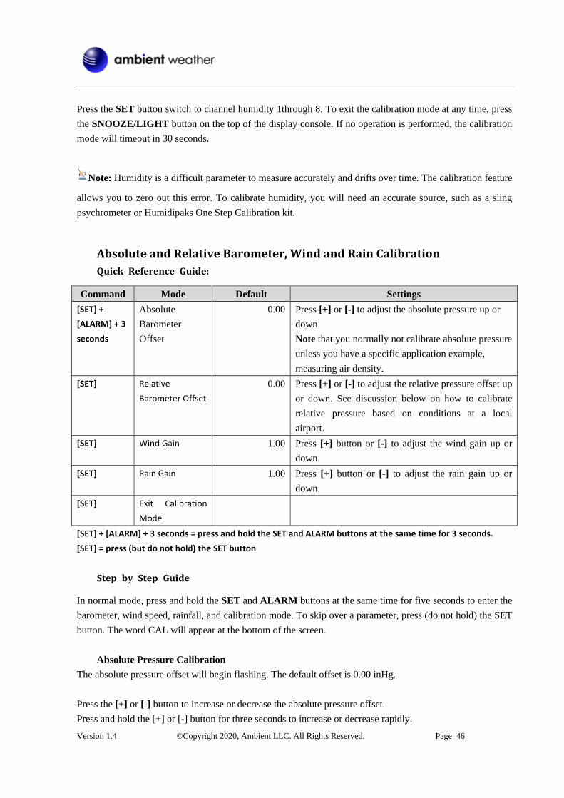
Absolute and Relative Barometer, Wind and Rain Calibration
Quick Reference Guide:
Command Mode Default Settings
[SET] +
[ALARM] + 3
seconds
Absolute
Barometer
Offset
0.00
Press [+] or [-] to adjust the absolute pressure up or
down.
Note that you normally not calibrate absolute pressure
unless you have a specific application example,
measuring air density.
[SET] Relative
Barometer Offset
0.00 Press [+] or [-] to adjust the relative pressure offset up
or down. See discussion below on how to calibrate
relative pressure based on conditions at a local
airport.
[SET] Wind Gain 1.00 Press [+] button or [-] to adjust the wind gain up or
down.
[SET] Rain Gain 1.00 Press [+] button or [-] to adjust the rain gain up or
down.
[SET] Exit Calibration
Mode
[SET] + [ALARM] + 3 seconds = press and hold the SET and ALARM buttons at the same time for 3 seconds.
[SET] = press (but do not hold) the SET button
Step by Step Guide
In normal mode, press and hold the SET and ALARM buttons at the same time for five seconds to enter the
barometer, wind speed, rainfall, and calibration mode. To skip over a parameter, press (do not hold) the SET
button. The word CAL will appear at the bottom of the screen.
Absolute Pressure Calibration
The absolute pressure offset will begin flashing. The default offset is 0.00 inHg.
Press the [+] or [-] button to increase or decrease the absolute pressure offset.
Press and hold the [+] or [-] button for three seconds to increase or decrease rapidly.

Version 1.4 ©Copyright 2020, Ambient LLC. All Rights Reserved. Page 47
Press the ALARM button to reset current value.
Example: The calibrated pressure source measures 28.00 inHg. The display absolute pressure reads 28.83
inHg on the console.
Offset = 28.00 – 28.83 = 0.83 inHg.
Relative Pressure Calibration
Press the SET button and the relative pressure offset will flash. The default is 0.00 inHg
Press the [+] or [-] button to increase or decrease the relative pressure offset.
Press and hold the [+] or [-] button for three seconds to increase or decrease rapidly.
Press the ALARM button to reset current value.
Example: The local official barometer measures 30.00 inHg. The display absolute pressure reads 29.92 inHg
on the console.
Offset = 30.00 – 29.92 = 0.08 inHg.
Note: The display console displays two different pressures: absolute (measured) and relative (corrected
to sea-level).
To compare pressure conditions from one location to another, meteorologists correct pressure to sea-level
conditions. Because the air pressure decreases as you rise in altitude, the sea-level corrected pressure (the
pressure your location would be at if located at sea-level) is generally higher than your measured pressure.
Thus, your absolute pressure may read 28.62 inHg (969 mb) at an altitude of 1000 feet (305 m), but the
relative pressure is 30.00 inHg (1016 mb).
The standard sea-level pressure is 29.92 in Hg (1013.2hpa). This is the average sea-level pressure around the
world. Relative pressure measurements greater than 29.92 inHg (1013.2hpa) are considered high pressure
and relative pressure measurements less than 29.92 inHg are considered low pressure.
To determine the relative pressure for your location, locate an official reporting station near you (the internet
is the best source for real time barometer conditions, such as Weather.com or Wunderground.com), and set
your weather station to match the official reporting station.
Wind Gain Calibration
Press the SET button and the wind gain will flash. The default is 1.00 (the display will show 100 but it is
actually 1.00. There is no provision for the decimal point).
Press the [+] or [-] button to adjust the wind speed calibration factor from 0.75 to 1.25, where:

Version 1.4 ©Copyright 2020, Ambient LLC. All Rights Reserved. Page 48
Calibrated Wind Speed = Calibration factor x Measured Wind Speed
Press and hold the [+] or [-] button for three seconds to increase or decrease rapidly.
Press the ALARM button to reset current value.
Note: The wind gust is also affected by the wind speed calibration factor.
Discussion: Wind speed and wind gust are adversely affected by installation constraints. The rule of
thumb is to install the weather station four times the distance of the height of the tallest obstruction (for
example, a 6 m house would require an installation 24 m away).
In many instances, due to trees and other obstructions, this is not possible. The wind speed calibration allows
you to correct for these obstructions.
In addition to installation challenges, wind speed bearings (any moving part) wears over time. To correct for
wear, the correction value can be increased until the wind cups must be replaced.
Without a calibrated source, wind speed is a difficult parameter to measure. We recommend using a calibrated
wind meter and constant, high speed fan.
Rain Calibration
Press the SET button again and the Rain Calibration value will begin flashing (the default is 1.0). Press the [+]
or [-] button to adjust the rain calibration factor from 0.75 to 1.25, where:
Calibrated Rain = Calibration factor x Measured Rain
Press and hold the [+] or [-] button for three seconds to increase or decrease rapidly.
Press the ALARM button to reset current value.
Discussion: The rain collector is calibrated at the factory based on the funnel diameter. The bucket tips
every 0.01” of rain (referred to as resolution). The accumulated rainfall can be compared to a sight glass rain
gauge with an aperture of at least 4”.
Note: that debris and insects can collect inside the tipping mechanism (they make a good spider’s nest).
Carefully remove the funnel and inspect the tipping mechanism for debris prior
to calibration.
Clearing Rain Totals
While in Normal Mode, Press (do not hold) the SET button twice and the rain field will flash.
Press the CHANNEL/+ or MIN/MAX/- button to toggle between 1h, 24h, week, month and total.

Version 1.4 ©Copyright 2020, Ambient LLC. All Rights Reserved. Page 49
To clear the hourly rain, press the CHANNEL/+ until 1h is flashing. Press and hold the SET button for 5
seconds until 1h reads 0.
To clear 24-hour rain, press the CHANNEL/+ until 24h is flashing. Press and hold the SET button for 5
seconds until 24h reads 0. This will also clear 1h rain.
To clear weekly rain, press the CHANNEL/+ until week is flashing. Press and hold the SET button for 5
seconds until week reads 0. This will also clear 1h and 24h rain.
To clear monthly rain, press the CHANNEL/+ until month is flashing. Press and hold the SET button for
5 seconds until month reads 0. This will also clear 1h, 24h and week rain.
To clear total rain, press the CHANNEL/+ until total is flashing. Press and hold the SET button for 5
seconds until total reads 0. This will also clear 1h, 24h, week and total rain.
Alarm Mode
The WS-50-C includes time alarm, temperature alarm and humidity alarm features for indoor and Channel 1,
feels like and dew point alarm for Channel 1, wind speed, wind gust, rainfall (1h and 24h) and pressure
(ABS and REL) alarm.
An alarm limit is exceeded when the measured value is below the LOW alarm setting, or the measured value
is above the HI alarm setting.
Alarm Operation
When an alarm condition is exceeded, the alarm icon will flash (visual) and the alarm beeper will
sound (audible). To silence the beeper, press any button. The alarm beeper can be permanently silenced by
referencing Section 0.
Viewing the High and Low Alarms
The console includes two time of day audible alarms (AL1 and AL2), indoor, channel 1, wind speed, wind
gust, pressure, and rainfall (1h and 24h) alarms are supported. Channels 2-8 alarms are not supported.
To view the high and low alarm settings, press (do not hold) the ALARM button to enter the alarm viewing
mode.
The HI alarms will be displayed along with the Alarm 1 Time (AL1).
Press (do not hold) the SET button to toggle between
Temperature, Dew Point and Feels Like
Absolute (ABS) and Relative (REL) Pressure
1 hour and 24-hour rain
Version 1.4 ©Copyright 2020, Ambient LLC. All Rights Reserved. Page 50
Alarm 1 and Alarm 2.
Press the ALARM button again to enter the alarm viewing mode to view LOW alarms along with the Alarm
2 Time (AL2).
Press (do not hold) the SET button to toggle between
Temperature, Dew Point and Feels Like
Absolute (ABS) and Relative (REL) Pressure
Alarm 1 and Alarm 2.
Press the SNOOZE/LIGHT button at any time to return to the normal mode.
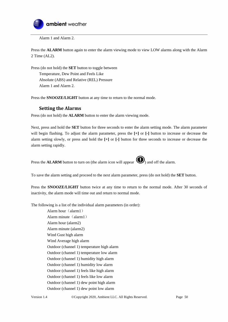
Setting the Alarms
Press (do not hold) the ALARM button to enter the alarm viewing mode.
Next, press and hold the SET button for three seconds to enter the alarm setting mode. The alarm parameter
will begin flashing. To adjust the alarm parameter, press the [+] or [-] button to increase or decrease the
alarm setting slowly, or press and hold the [+] or [-] button for three seconds to increase or decrease the
alarm setting rapidly.
Press the ALARM button to turn on (the alarm icon will appear ) and off the alarm.
To save the alarm setting and proceed to the next alarm parameter, press (do not hold) the SET button.
Press the SNOOZE/LIGHT button twice at any time to return to the normal mode. After 30 seconds of
inactivity, the alarm mode will time out and return to normal mode.
The following is a list of the individual alarm parameters (in order):
Alarm hour(alarm1)
Alarm minute(alarm1)
Alarm hour (alarm2)
Alarm minute (alarm2)
Wind Gust high alarm
Wind Average high alarm
Outdoor (channel 1) temperature high alarm
Outdoor (channel 1) temperature low alarm
Outdoor (channel 1) humidity high alarm
Outdoor (channel 1) humidity low alarm
Outdoor (channel 1) feels like high alarm
Outdoor (channel 1) feels like low alarm
Outdoor (channel 1) dew point high alarm
Outdoor (channel 1) dew point low alarm

Version 1.4 ©Copyright 2020, Ambient LLC. All Rights Reserved. Page 51
Rainfall (1h) high alarm
Rainfall (24h) high alarm
Absolute pressure high alarm
Absolute pressure low alarm
Relative pressure high alarm
Relative pressure low alarm
Indoor temperature high alarm
Indoor temperature low alarm
Indoor humidity high alarm
Indoor humidity low alarm
Alarm and Command Button Beeper ON/OFF Mode
The beeper can be silenced for both alarms and button strokes.
In normal mode, press and hold the ALARM button for three seconds to toggle the beeper on or off
(depending on the current setting).
The BUZZ ON (beeper on) or BUZZ OFF (beeper off) icon will appear in the time area for three seconds.
Press and hold the ALARM button again for three seconds to toggle the BUZZ ON or BUZZ OFF.
Wi-Fi Connection Status
When the console successfully connects to your Wi-Fi router, the Wi-Fi signal icon will appear on
the LCD display (in front of the indoor temperature). If the Wi-Fi signal is not stable or the console is trying
to connect to the router, the icon will flash. If the icon disappears, it means the console is not connected to
the Wi-Fi router.
Note: If you own a dual band router (2.4 GHz and 5.0 GHz), make sure you connect to the 2.4 GHz band,
otherwise it will fail to connect the weather station to Wi-Fi.
Time Server Sync Status
After the console has connected to the internet, it will attempt to connect to the USA's NIST internet time
server to obtain the time. Once the connection succeeds and the console's time has updated, the SYNC icon
will appear on the LCD. The time will automatically synchronize to the internet per an hour.
Wi-Fi and Internet Services
IMPORTANT NOTE: Make sure the console is plugged into AC power. It will not connect to Wi-Fi
otherwise.

Version 1.4 ©Copyright 2020, Ambient LLC. All Rights Reserved. Page 52
The WS-50-C includes a Wi-Fi chip that connects to the 2.4 GHz band on your router and sends data
automatically once per minute to our cloud services, AmbientWeather.net.
AmbientWeather.net captures, stores, and sends data to other services, such as WeatherUndergroud.com,
PWSWeather.com, IFTTT, Amazon Alexa, Google Home and more. Application Programming Interface
(API) is available for programmers and third-party programmers.
Connect your Device to the Console's Wi-Fi
Make sure your console is plugged into AC power. It will not connect to Wi-Fi otherwise.
When you first power up the console, or press and hold the MIN/MAX- button for three seconds, the Wi-Fi
icon will flash to signify that it has entered wireless access point (WAP) mode, and is ready to
connect to the console's Wi-Fi.
You can use your desktop, laptop, tablet, or smart phone to connect to the console's Wi-Fi. The console's
network name begins with WeatherHome, followed by a unique code.
Once completed, you will return your device to the normal Wi-Fi settings.
Example 1. Connect to the console Wi-Fi server with a PC.
Choose Wi-Fi network settings from Windows (or search “Change Wi-Fi Settings” from Windows), and
Connect to the WeatherHome, as shown in Figure 52 (your Wi-Fi network name may be slightly different
but will always begin with WeatherHome).
Figure 52

Version 1.4 ©Copyright 2020, Ambient LLC. All Rights Reserved. Page 53
Example 2. Connect to the console Wi-Fi server with a Mac.
Select the Settings icon and Network. Connect to the WeatherHome Wi-Fi network, as shown
in Figure 53 (your Wi-Fi network name may be slightly different but will always begin with WeatherHome).
Figure 53
Example 3. Connect to the console Wi-Fi server with an iPhone or iPad.
Tap the Settings icon and Wi-Fi. Connect to the WeatherHome Wi-Fi network, as shown in Figure 54
(your Wi-Fi network name may be slightly different but will always begin with WeatherHome).

Version 1.4 ©Copyright 2020, Ambient LLC. All Rights Reserved. Page 54
Figure 54
Example 4. Connect to the console Wi-Fi server with an Android.
From the Apps icon, tap the Settings icon and Wi-Fi. Connect to the WeatherHome Wi-Fi network, as
shown in Figure 55 (your Wi-Fi network name may be slightly different but will always begin with
WeatherHome).
Figure 55
Accessing the Console's Web Interface

Version 1.4 ©Copyright 2020, Ambient LLC. All Rights Reserved. Page 55
Once connected to the console Wi-Fi, open any web browser, and enter the following IP address into the
address bar:
http://192.168.5.1
to access the console's web interface.
Note: Some browsers will treat 192.168.5.1 as a search, so make sure you include the header http://,
or: http://192.168.5.1 not 192.168.5.1.
Enter your 2.4 GHz router name or SSID, password, time zone and Daylight-Saving Time into the web
interface (Figure 56), and tap Save.
Figure 56
Notes:
Make a note of your Mac address. You will need this to register at AmbientWeather.net.

Version 1.4 ©Copyright 2020, Ambient LLC. All Rights Reserved. Page 56
If you have a hidden SSID, enter the SSID manually.
Time Zone Settings (default: 0h). based on the number of hours from Coordinated Universal Time, or
Greenwich Mean Time (GMT).
The following table provides times zones throughout the world. Locations in the eastern hemisphere are
positive, and locations in the western hemisphere are negative.
Hours from
GMT
Time Zone Cities
-12 IDLW: International Date Line West ---
-11 NT: Nome Nome, AK
-10 AHST: Alaska-Hawaii Standard
CAT: Central Alaska
HST: Hawaii Standard
Honolulu, HI
-9 YST: Yukon Standard Yukon Territory
-8 PST: Pacific Standard Los Angeles, CA, USA
-7 MST: Mountain Standard Denver, CO, USA
-6 CST: Central Standard Chicago, IL, USA
-5 EST: Eastern Standard New York, NY, USA
-4 AST: Atlantic Standard Caracas
-3 --- São Paulo, Brazil
-2 AT: Azores Azores, Cape Verde Islands
-1 WAT: West Africa ---
0 GMT: Greenwich Mean
WET: Western European
London, England
1 CET: Central European Paris, France
2 EET: Eastern European Athens, Greece
3 BT: Baghdad Moscow, Russia
4 --- Abu Dhabi, UAE
5 --- Tashkent
6 --- Astana
7 --- Bangkok
8 CCT: China Coast Bejing
9 JST: Japan Standard Tokyo
10 GST: Guam Standard Sydney
11 --- Magadan
12 IDLE: International Date Line East
NZST: New Zealand Standard
Wellington, New Zealand
Once the setup is complete, disconnect your device from the console Wi-Fi. Otherwise, the console will
automatically exit WAP mode.

Version 1.4 ©Copyright 2020, Ambient LLC. All Rights Reserved. Page 57
Figure 57
If the connection is successful, the Wi-Fi console's Wi-Fi icon will stop flashing and remain on.
When the console successfully connects and uploads to AmbientWeather.net, the data signal icon will
appear above the Wi-Fi icon. If the data signal icon is flashing, the console is currently uploading to
the server. If the icon disappears, the console is not connected to the weather server for more than 30
minutes.
AmbientWeather.net
Registering with AmbientWeather.net
Visit: www.AmbientWeather.net to create an account and select Add Device, as shown in Figure 58.
Figure 58
Next, enter the MAC address found on your Weather Station Web Interface (Figure 29). Note that

Version 1.4 ©Copyright 2020, Ambient LLC. All Rights Reserved. Page 58
55:55:55:55:55:55 is an example only and your MAC address will be different.
Figure 29
Register an account on AmbientWeather.net (email address and password).
Once registered, select the dashboard to view your data, as shown in Figure 59.
Figure 59
Ambient Weather Apps
You can view your device online either through a web browser, or apps for Android and iOS devices.
AmbientWeather.net is a responsive design and mobile friendly, so there is no need for an app on your
desktop, laptop, tablet, or mobile device. Simply open your web browser, browse to AmbientWeather.net,
and bookmark your dashboard.

Version 1.4 ©Copyright 2020, Ambient LLC. All Rights Reserved. Page 59
The Ambient Weather Dashboard app is available on both Android and iOS. Search the Google or
Apple Store for Ambient Weather Dashboard.
Third Party Public Websites
WeatherUnderground.com and PWSWeather.com are third party public websites.
You can also report to these websites through the AmbientWeather.net hosting service. To register and send
data to the websites, go to the Devices panel on your AmbientWeather.net dashboard:
https://dashboard.ambientweather.net/devices
Note: The current temperature and humidity data is the transmitter of CH1 (so it must on the outside).
AmbientWeather.net Works with and Community
AmbientWeather.net works with IFTTT, Amazon Alexa, Google Home, Home Assistant, SmartThings, and
a variety of other third-party apps. There is also an API for developers.
Learn more at:
https://www.ambientweather.com/community.html
Updating Firmware
To find firmware updates, please visit:
https://ambientweather.net/product/WS-50-C/
Note that you must download the firmware update file to your PC or Mac. You cannot download a file to
your tablet or mobile phone.
When you first power up the console, or press and hold the MIN/MAX- button for three seconds, the Wi-Fi
icon will flash to signify that it has entered wireless access point (WAP) mode, and is ready to
connect to the console's Wi-Fi.
Connect to the console's Wi-Fi. The console's network name begins with WeatherHome, followed by a
unique code.
Once completed, you will return your device to the normal Wi-Fi settings.

Version 1.4 ©Copyright 2020, Ambient LLC. All Rights Reserved. Page 60
Once connected to the console Wi-Fi, open any web browser, and enter the following IP address into the
address bar:
http://192.168.5.1/upgrade.html
to access the console's upgrade web interface.
Tap Select File and browse to the binary (bin) file you downloaded to your PC or Mac.
Figure 60
Once complete, you must reset the console to factory default:
1. Unplug the power adaptor,
2. Press and hold the MIN/MAX/- button and plug in the power adaptor,
3. Wait three seconds after plugging in the AC adapter to let go of the MIN/MAX/- button.
Glossary of Terms

Version 1.4 ©Copyright 2020, Ambient LLC. All Rights Reserved. Page 61
Term Definition
Accuracy Accuracy is defined as the ability of a measurement to match the
actual value of the quantity being measured.
Hygrometer A hygrometer is a device that measures relative humidity. Relative
humidity is a term used to describe the amount or percentage of
water vapor that exists in air.
Range Range is defined as the amount or extent a value can be measured.
Resolution Resolution is defined as the number of significant digits (decimal
places) to which a value is being reliably measured.
Wind Vane A wind vane is a device that measures the direction of the wind. The
wind vane is usually combined with the anemometer. Wind direction
is the direction from which the wind is blowing.
Absolute Barometric
Pressure
Relative barometric pressure corrected to sea-level. To compare
pressure conditions from one location to another, meteorologists
correct
pressure to sea-level conditions. Because the air pressure decreases
as
you rise in altitude, the sea-level corrected pressure (the pressure
your
location would be at if located at sea-level) is generally higher than
your
measured pressure.
Relative Barometric
Pressure
Measured barometric pressure relative to your location or ambient
conditions.
HectoPascals (hPa) Pressure units in SI (international system) units of measurement.
Same
as millibars (1 hPa = 1 mbar)
Inches of Mercury (inHg) Pressure in Imperial units of measure.
1 inch of mercury = 33.86 millibars
Specifications
Wireless Specifications
Line of sight wireless transmission (in open air): 300 feet, 100 feet under most conditions
Frequency: 433 MHz
Update Rate: 60 seconds for rain sensor and thermo-hygrometer sensor, 16 seconds for wind sensor.
Measurement Specifications

Version 1.4 ©Copyright 2020, Ambient LLC. All Rights Reserved. Page 62
The following table provides specifications for the measured parameters.
The following table provides specifications for the measured parameters.
Measurement Range Accuracy Resolution
Indoor Temperature 32 to 140 °F ± 1 °F 0.1 °F
Outdoor Temperature -40 to 140 °F ± 1 °F 0.1 °F
Indoor Humidity 10 to 99 % ± 5% (only guaranteed
between 20 to 90%)
1 %
Outdoor Humidity 10 to 99% ± 5% (only guaranteed
between 20 to 90%)
1 %
Rain 0 to 396in <0.6in: ±0.04in,
0.6in to 396in: ±7%
<39.4in (0.012 in)
>39.4in (0.04 in)
Wind Direction 0 - 360 º 45º (8-point compass) 45º (8-point
compass)
Wind Speed 0 to 112mph 4.5 mph ~22.4mph: ±
6.7mph, 22.4mph ~112mph:
±10% (whichever is greater)
0.1mph
Barometric Pressure:
8.85 to 32.50 inHg
± 0.08 inHg
inHg
Power Consumption
Display Console: 4 x AAA 1.5V Alkaline or Lithium batteries (not included)
Adaptor: 6V~ 500mA
Thermo-Hygro Sensor: 2 x AAA alkaline batteries or Lithium batteries (not included)
Rain sensor: 4 x AAA alkaline batteries or Lithium batteries (not included)
Wind sensor: 4 x AAA alkaline batteries or Lithium batteries (not included)
Battery life: Minimum 12 months for base station with excellent reception. Intermittent reception
and multiple sensors may reduce the battery life.
Minimum 12 months for sensors (use lithium batteries in cold weather climates less than -4 °F)
Wi-Fi Specifications
WIFI Standard: 802.11 b/g/n
Wi-Fi Console Wi-Fi Frequency: 2.4 GHz
Setup User Interface (UI) support setup device: Build-in Wi-Fi with WAP mode smart device,
including desktops, laptops, tablets, or mobile devices
Recommend web browser for setup UI: Web browser support of HTML 5, such as the latest
versions of Chrome, Safari, IE, Edge, Firefox, Mozilla, or Opera.
Line of sight Wi-Fi RF transmission (in open air): 80 feet

Version 1.4 ©Copyright 2020, Ambient LLC. All Rights Reserved. Page 63
Maintenance
Clean the rain gauge once every 3 months. Pull out the Rain Gauge Filter drawer, as shown in Section
6.2.1.
Replace the wind, rain, and thermo-hygrometer transmitter batteries once every 1-2 years
Clean the anemometer solar panel once every 3 months.
Accessories
The following software and hardware accessories are available for this weather station at
www.AmbientWeather.com .
Accessory Description
Energizer AAA Lithium
Battery (2-pack) - Batteries
for Long Life and Cold
Climates
AAA lithium batteries for cold weather climates.
Energizer AA Lithium
Battery (2-pack) - Batteries
for Long Life and Cold
Climates
AA lithium batteries for cold weather climates.
Ambient Weather
SRS100LX Temperature
and Humidity Solar
Radiation Shield
Solar Radiation Shield improves temperature accuracy for hot weather
climates. Install over thermo-hygrometer.
Ambient Weather Humidity
Calibration Kits
One step calibration kits for digital hygrometers use salt slurry formula
to accurately calibrate the indoor and outdoor hygrometers.
Liability Disclaimer
Please help in the preservation of the environment and return used batteries to an authorized depot.
The electrical and electronic wastes contain hazardous substances. Disposal of electronic waste in wild
country and/or in unauthorized grounds strongly damages the environment.
Reading the “User manual” is highly recommended. The manufacturer and supplier cannot accept any
responsibility for any incorrect readings and any consequences that occur should an inaccurate reading take
place.
This product is designed for use in the home only as indication of weather conditions. This product is not to
be used for medical purposes or for public information.
The specifications of this product may change without prior notice.

Version 1.4 ©Copyright 2020, Ambient LLC. All Rights Reserved. Page 64
This product is not a toy. Keep out of the reach of children.
No part of this manual may be reproduced without written authorization of the manufacturer.
Ambient, LLC WILL NOT ASSUME LIABILITY FOR INCIDENTAL, CONSEQUENTIAL, PUNITIVE,
OR OTHER SIMILAR DAMAGES ASSOCIATED WITH THE OPERATION OR MALFUNCTION OF
THIS PRODUCT.
FCC Statement
Statement according to FCC part 15.19:
This device complies with part 15 of the FCC rules. Operation is subject to the following two conditions:
This device may not cause harmful interference.
This device must accept any interference received, including interference that may cause
undesired operation.
Statement according to FCC part 15.21:
Modifications not expressly approved by this company could void the user's authority to operate the
equipment.
Statement according to FCC part 15.105:
NOTE: This equipment has been tested and found to comply with the limits for a Class B digital device,
pursuant to Part 15 of the FCC Rules. These limits are designed to provide reasonable protection against
harmful interference in a residential installation. This equipment generates, uses, and can radiate radio
frequency energy and, if not installed and used in accordance with the instructions, may cause harmful
interference to radio communications.
However, there is no guarantee that interference will not occur in an installation. If this equipment does
cause harmful interference to radio or television reception, which can be determined by turning the
equipment off and on, the user is encouraged to try to correct the interference by one or more of the
following measures:
Reorient or relocate the receiving antenna.
Increase the separation between the equipment and receiver.
Connect the equipment into an outlet on a circuit different from that to which the receiver is
connected.
Consult the dealer or an experienced radio/TV technician for help.
Warranty Information
Ambient, LLC provides a 1-year limited warranty on this product against manufacturing defects in materials
and workmanship.
This limited warranty begins on the original date of purchase, is valid only on products purchased and only
to the original purchaser of this product. To receive warranty service, the purchaser must contact Ambient,
LLC for problem determination and service procedures.

Version 1.4 ©Copyright 2020, Ambient LLC. All Rights Reserved. Page 65
Warranty service can only be performed by Ambient, LLC. The original dated bill of sale must be presented
upon request as proof of purchase to Ambient, LLC.
Your Ambient, LLC warranty covers all defects in material and workmanship with the following specified
exceptions: (1) damage caused by accident, unreasonable use or neglect (lack of reasonable and necessary
maintenance); (2) damage resulting from failure to follow instructions contained in your owner's manual; (3)
damage resulting from the performance of repairs or alterations by someone other than an authorized
Ambient, LLC authorized service center; (4) units used for other than home use (5) applications and uses
that this product was not intended (6) the products inability to receive a signal due to any source of
interference or metal obstructions and (7) extreme acts of nature, such as lightning strikes or floods.
This warranty covers only actual defects within the product itself and does not cover the cost of installation
or removal from a fixed installation, normal set-up or adjustments, claims based on misrepresentation by the
seller or performance variations resulting from installation-related circumstances.
California Prop 65
WARNING: Use of the Ambient Weather Products can expose you to chemicals, including lead and lead
compounds, which are known to the State of California to cause cancer and bisphenol A (BPA), and
phthalates DINP and/or DEHP, which are known to the State of California to cause birth defects or other
reproductive harm.
Can I Trust that Ambient Weather Products are Safe Despite this Warning?
In 1986, California voters approved the Safe Drinking Water and Toxic Enforcement Act known as
Proposition 65 or Prop 65. The purpose of Proposition 65 is to ensure that people are informed about
exposure to chemicals known by the State of California to cause cancer, birth defects and/or other
reproductive harm. A company with ten or more employees that operates within the State of California (or
sells products in California) must comply with the requirements of Proposition 65. To comply, businesses
are: (1) prohibited from knowingly discharging listed chemicals into sources of drinking water; and (2)
required to provide a "clear and reasonable" warning before knowingly and intentionally exposing anyone to
a listed chemical. Proposition 65 mandates that the Governor of California maintain and publish a list of
chemicals that are known to cause cancer, birth defects and/or other reproductive harm. The Prop 65 list,
which must be updated annually, includes over 1,000 chemicals, including many that are commonly used in
the electronics industry.
Although our manufacturing process is "lead-free" and RoHS compliant, it remains possible that trace
amounts of lead could be found in components or subassemblies of Ambient Weather Products. Bisphenol A
(BPSA) could conceivably be present in minute amounts in our plastic housings, lenses, labels, or adhesives,
and DEHP & DINP (phthalates) could possibly be found in PVC wire coatings of our cables, housings, and
power cords. Unlike RoHS, Prop 65 does not establish a specific threshold for reporting on the substances of
concern and instead sets forth a much less definitive standard requiring that the business demonstrate with
certainty that there is "no significant risk" resulting from exposure. With respect to carcinogens, the "no

Version 1.4 ©Copyright 2020, Ambient LLC. All Rights Reserved. Page 66
significant risk" level is defined as the level which is calculated to result in not more than one excess case of
cancer in 100,000 individuals exposed over a 70-year lifetime. In other words, if you are exposed to the
chemical in question at this level every day for 70 years, theoretically, it will increase your chances of
getting cancer by no more than 1 case in 100,000 individuals so exposed. With respect to reproductive
toxicants, the "no significant risk" level is defined as the level of exposure which, even if multiplied by
1,000, will not produce birth defects or other reproductive harm. In other words, the level of exposure is
below the "no observable effect level," divided by 1,000. (The "no observable effect level" is the highest
dose level which has not been associated with observable reproductive harm in humans or test animals.)
Proposition 65 does not clarify whether exposure is to be measured only in normal operation, or in the event
of misuse such as intentionally damaging, incinerating or
consuming an Ambient Weather Product or component and Ambient Weather has not attempted to evaluate
the level of exposure.
A Proposition 65 warning means one of two things: (1) the business has evaluated the exposure and has
concluded that it exceeds the "no significant risk level"; or (2) the business has chosen to provide a warning
simply based on its knowledge about the presence of a listed chemical without attempting to evaluate the
exposure. The California government has itself clarified that "The fact that a product bears a Proposition 65
warning does not mean by itself that the product is unsafe." The government has also explained, "You could
think of Proposition 65 more as a 'right to know' law than a pure product safety law."
While using Ambient Weather Products as intended, we believe any potential exposure would be
negligible or well within the "no significant risk" range. However, to ensure compliance with
California law and our customers' right to know, we have elected to place the Proposition 65 warning
signs on Ambient Weather Products.
For further information about California's Proposition 65, please
visit https://oehha.ca.gov/prop65/background/p65plain.html