Ffff fisheries and finance presentation 2013 tasha sutcliffe
Upload
ambrose-hodgesCategory
view
225download
4
Amateur Radio Digital Modes
Gary Sutcliffe, W9XTJanuary 14, 2015

What Are Digital Modes?• The digital modes use a computer to generate and
decode the transmitted signals.• Traditionally this was done by circuits with capacitors,
inductors, resistors, amplifiers, etc.• Most of these use the sound card as a digital signal
processor (DSP).

Some Common Digital Modes
Originally Analog● RTTY● SSTV● Fax● Hellscriber
Developed for PC
PSK31
JT65
FSK441
WSPR

What is Digital? • Let’s start with what is analog?
• It is continuous – there are an infinite number of points between any arbitrary two points
• In theory you can measure the voltage to any resolution
V= 1.643094128441…
Infinite number of points between these points

Let’s digitize the signal
Measure the voltage at regular intervals
Samples are taken with an Analog to Digital (A/D) Converter which is essentially a voltmeter.

With a digitized signal
We can perform math on the data, and then convert the results back to a voltage with a Digital to Analog (D/A) converter.

A simple digital low pass filter
1. Digitize the signal2. For each point, add the value of the point, the previous point andthe next point and divide by 33. Convert the new values back to a voltage
0.185424
0.549383
0.651308
0.888572
0.831386
1.052738
1.033471
0.831724
0.849558
0.585576
0.459885
0.245268
-0.10869
-0.39857
0.244936
0.462038
0.696421
0.790422
0.924232
0.972532
0.972644
0.904917
0.755619
0.631673
0.430243
0.198822
-0.08733
-0.35708
Original Averaged
Noisy input Filtered output

If• You have fast enough A/D and D/A circuits with enough
resolution• You have a fast enough computer• You are good enough with the math
You can• Create extraordinary filters, very narrow, no ringing• Convert from the time domain to frequency domain
(spectral analysis)• Pull weak signals out of the noise• Modulate/demodulate signals• Do all sorts of other magic

Why is DSP Better Than Analog Circuits?
DSP• Can change function with just a software change
• Frequency reference is the only part that might age
Analog components• Need to be tuned
• Change value with age, temperature, etc.
• Can be expensive and bulky

Some DSP rules of thumb• If you sample the signal at least twice the highest
frequency present, you can reproduce it (Nyquist Criteria)• The more you know about the signal, the deeper you can
pull it out of the noise.• The slower the signal changes (in frequency and/or
amplitude), the deeper you can pull it out of the noise.
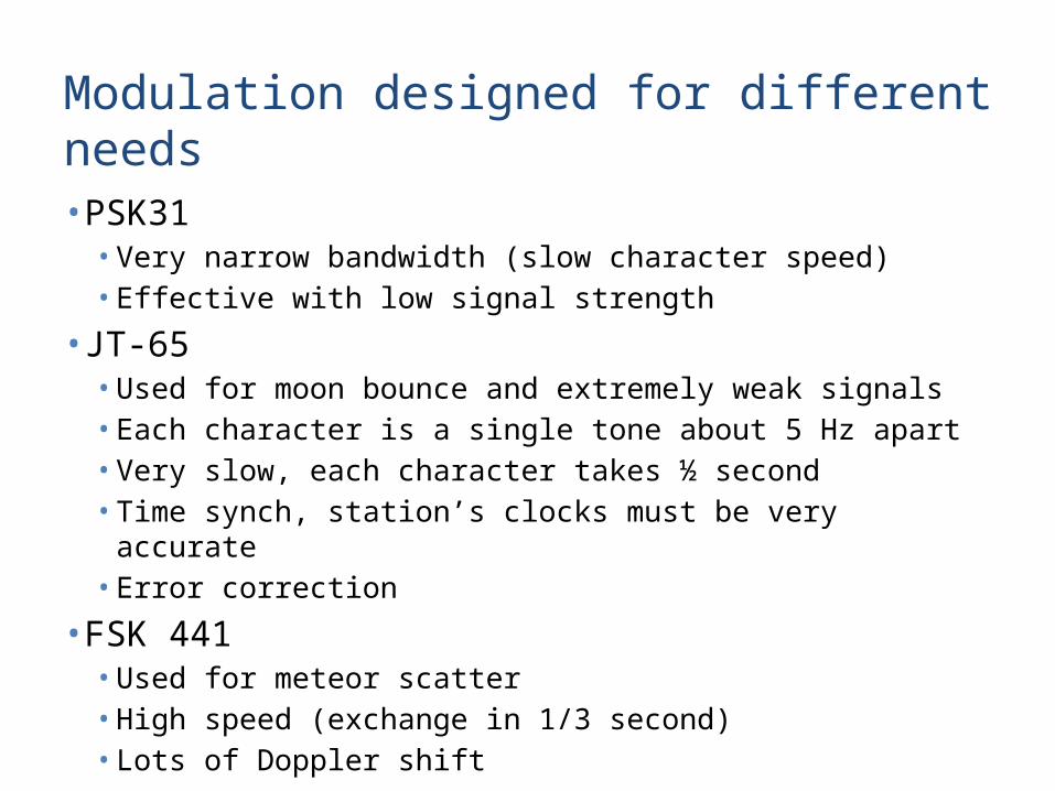
Modulation designed for different needs
• PSK31• Very narrow bandwidth (slow character speed)• Effective with low signal strength
• JT-65• Used for moon bounce and extremely weak signals• Each character is a single tone about 5 Hz apart• Very slow, each character takes ½ second• Time synch, station’s clocks must be very accurate• Error correction
• FSK 441• Used for meteor scatter• High speed (exchange in 1/3 second)• Lots of Doppler shift

Enough theory!
On to the fun stuff!

What do you need to go digital?
•Stuff you probably already have•Radio – SSB capable•Computer with sound card
•Stuff you need to get•Computer to radio interface (build or buy)•Software – most is free!

Computer-Radio Interface
Schematic and photo courtesy of Unified Microsystems www.unifiedmicro.com

Digital modes use SSB to transmit
But most of the digital modes are out of the phone band. Isn’t that illegal?

Digital Modes Used at W9XT• There are other modes I have not yet tried• The following programs are the ones I use. There are
others available that you might like better

RTTY• Uses BAUDOT code • Goes back to first mechanical printers• Probably most popular digital mode• Can be a plug-in to some logging programs

MMTTY - RTTY program

PSK31• Very narrow banded• Excellent weak signal effectiveness• Popular – set off the PC/sound card digital mode
revolution in 1999• Sensitive to phase distortion on long paths• Somewhat slow – a good typist can go faster than
transmission rate

Digipan - PSK 31Program

JT-65 • Developed for moon bounce by K1JT• Extremely low signal levels, slow Doppler shift• Excellent weak signal, detect ~28 dB below RX noise• 65 tones, 5 HZ apart, ½ second dwell time• Each tone is a character• Very slow, about 1 minute to send calls & exchange• Requires accurate clocks at both stations• QSOs usually scheduled • Structured QSO sequence• Also being used on HF

JT-65 - Moon bounce program

FSK441• Developed for meteor scatter• Fairly strong signals• Short infrequent bursts – exchanges sent fast, repeated• Large Doppler shift• Takes advantage of short pings, increasing success rate• 30 second XMT/RX cycle• Structured QSO sequence• QSOs usually scheduled

FSK441 – Meteor scatter program

Summary• The digital modes are the cutting edge of technology in
ham radio• They lower the bar for power and antenna requirements
for some types of communications• There are additional modes not covered here• You can get on them for very little money