amaco.com AMACO KILNSamacofiles.com/files/amaco-kiln-manual-web.pdfManual Kiln Operation.....2936...
48
American Art Clay Co., Inc. • 6060 Guion Road, Indianapolis, Indiana 46254 AMACO ® KILNS OPERATING MANUAL amaco.com
Transcript of amaco.com AMACO KILNSamacofiles.com/files/amaco-kiln-manual-web.pdfManual Kiln Operation.....2936...

American Art Clay Co., Inc. • 6060 Guion Road, Indianapolis, Indiana 46254
AMACO® KILNS OPERATING MANUAL
amaco.com
Intr
oduc
tion
WelcomeYou have selected your kiln after much deliberation, and this booklet is planned to assist you in its installation, operation and maintenance.All electric kilns sold by AMACO® are safe and well built. All AMACO® kilns are listed with Un der writ ers Lab o ra tories, Inc. You can be assured that the com plete unit—not just switch es and certain parts—has met their rigid standards for safe ty in regard to ca su al ty and fire haz ards. Most schools and in sti tu tions re quire the UL seal on all elec tri cal equip ment. Important: Read this entire manual before doing anything else. Whether you have owned an elec tric kiln before or not, please take the time to read this manual from cover to cover. We think even the most ex pe ri enced veteran will learn a few new tips.
Limited WarrantyAll AMACO® kilns are guaranteed by AMACO® against defects in ma te ri als and workmanship to the original purchas er for a period of five years that covers parts and labor subject to these exclusions:Exclusions1. Damage due to misuse, including but not lim it ed to,
overfiring, improper installation, rough han dling, improp er stacking, malfunction of cut offs and start ers.
2. The KILNSITTER® (if equipped) is sep a rate ly warrant ed by its manufacturer, W.P. Dawson, Inc., 6441 S. E.Johnson Creek Blvd., Portland, OR 97206, (503) 7746000.
3. Shipping damage.4. The warranty period has expired.5. Repair or service is done by an unauthorized dealer.6. Damage or failure due to acts of God such as, fire,
flood, electrical storms, etc.7. Damage due to overfiring, reduction or salt glaz ing.8. Use for other than ceramic materials.9. Normal wear as experienced in the ceramic pro cess.10. Units modified in any manner.This warranty does not cover damage caused by failure of these in stru ments. The buyer’s sole and ex clu sive remedy shall be for the repair and/or re place ment of defective parts as provided herein. The buyer agrees that no other remedy (including, but not limited to, lost profits, lost sales, damage to property, or any other in ci den tal or consequential loss) shall be available to the buyer.
Warranty Repair InstructionsAll warranty claims must be approved and serviced by an authorized AMACO® dealer. If there is not an authorized AMACO® dealer in your area, contact AMACO® directly for authorization, however labor costs will not be covered. If you exprience a problem with your equipment:1. Contact the dealer or representative from whom you
made your purchase.2. If the dealer is unauthorized to perform repair or un
able to correct the problem: a. Call the AMACO® Support Department toll free @
18003741600 or 3172446871 (local). b. Email the AMACO/brent Technical Support Depart
ment at [email protected]. Provide the following information and the Technical
Support Agent will provide further assistance: a. Model number of item b. Serial number of item c. Voltage and phase of item d. Date purchased e. From whom purchased f. Nature of problemAMACO® recommends that all maintenance and repairs to kilns be performed by an Authorized AMACO® Service Technician, however if this is not possible AMACO® recommends that the owner work closely with our Technical Services representatives to ensure the diagnosis and repair are correct and performed safely. Normally, simple repairs can be made over the phone with our trained Technical Service Staff Monday–Friday 7:00 am–5:30 pm EST. If it is necessary to mail or ship parts to AMACO® for further inspection, parts must be sent prepaid. For your protection, insure all parts. The equipment and part serial number must accompany the defective item. Repair parts will be sent with a full refund on the invoice if examination confirms a de fect in materials or workmanship.If repairs must be made at the factory, it will be done at no charge for parts and labor provided all ship ping costs are supplied by the purchaser. Do not return any merchan dise without authorization. This warranty gives you specific legal rights. You may have other rights which vary from state to state.Your kiln is registered. We keep a per ma nent record of the serial number, model number and purchaser of every kiln sold. With this information, we can supply the necessary replacement parts for your par tic u lar kiln. Keep your papers in a safe place. You will want to refer to this instruction booklet, special kiln instructions, wiring di a gram and catalog. File them in a safe place for handy reference.
Thank You!Congratulations! You’ve made a great choice from the proven AMACO® kiln line.
1
Table of Contents
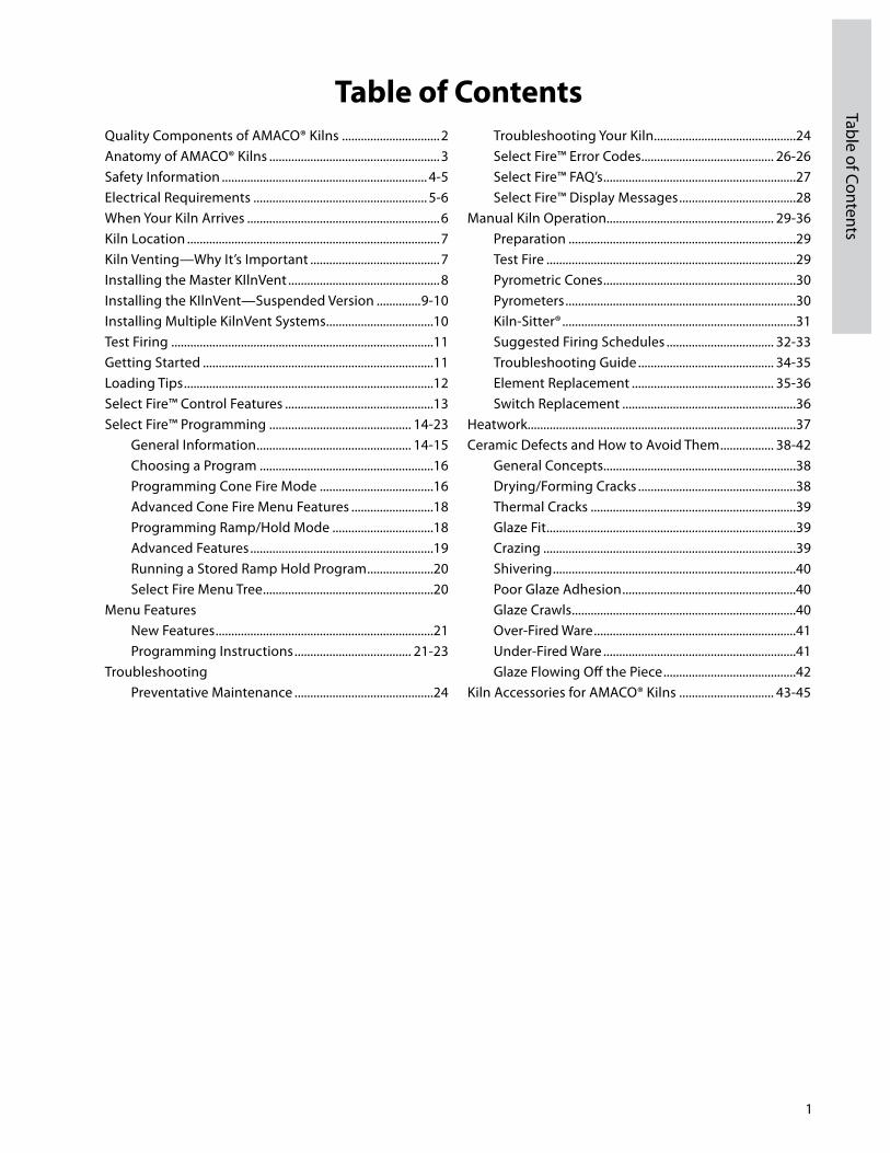
Table of ContentsQuality Components of AMACO® Kilns ...............................2Anatomy of AMACO® Kilns ......................................................3Safety Information ................................................................. 45Electrical Requirements ....................................................... 56When Your Kiln Arrives .............................................................6Kiln Location ................................................................................7Kiln Venting—Why It’s Important .........................................7Installing the Master KIlnVent ................................................8Installing the KIlnVent—Suspended Version ..............910Installing Multiple KilnVent Systems ..................................10Test Firing ...................................................................................11Getting Started .........................................................................11Loading Tips ...............................................................................12Select Fire™ Control Features ...............................................13Select Fire™ Programming ............................................. 1423 General Information ................................................. 1415 Choosing a Program .......................................................16 Programming Cone Fire Mode ....................................16 Advanced Cone Fire Menu Features ..........................18 Programming Ramp/Hold Mode ................................18 Advanced Features ..........................................................19 Running a Stored Ramp Hold Program .....................20 Select Fire Menu Tree ......................................................20Menu Features New Features .....................................................................21 Programming Instructions ..................................... 2123Troubleshooting Preventative Maintenance ............................................24
Troubleshooting Your Kiln .............................................24 Select Fire™ Error Codes .......................................... 2626 Select Fire™ FAQ’s .............................................................27 Select Fire™ Display Messages .....................................28Manual Kiln Operation..................................................... 2936 Preparation ........................................................................29 Test Fire ...............................................................................29 Pyrometric Cones .............................................................30 Pyrometers .........................................................................30 KilnSitter® ..........................................................................31 Suggested Firing Schedules .................................. 3233 Troubleshooting Guide ........................................... 3435 Element Replacement ............................................. 3536 Switch Replacement .......................................................36Heatwork.....................................................................................37Ceramic Defects and How to Avoid Them ................. 3842 General Concepts.............................................................38 Drying/Forming Cracks ..................................................38 Thermal Cracks .................................................................39 Glaze Fit ...............................................................................39 Crazing ................................................................................39 Shivering .............................................................................40 Poor Glaze Adhesion .......................................................40 Glaze Crawls .......................................................................40 OverFired Ware ................................................................41 UnderFired Ware .............................................................41 Glaze Flowing Off the Piece ..........................................42Kiln Accessories for AMACO® Kilns .............................. 4345

2
Qua
lity
Select Fire™ Controller (if equipped)At the heart of your new kiln is the Select Fire™ con trol ler. This unit allows you much greater con trol over your kiln than ever before. It is es sen tial ly two con trol lers in one. You can fire by cone numbers or spec i fy your own firing profile with multiple ramps and holds.The wall mounted Select Fire™ is an option that functions in the same manner as the builtin version with the ex cep tion that it can be moved from one kiln to another. While the wall mounted version can not fire more than one kiln at a time, it can control any number of kilns a studio op er ates provided they have the same cord plug and re cep ta cle configuration.
BrickAMACO® kilns are constructed of the fin est in sulat ing firebrick available today, offering strength, clean li ness and long life. All bricks are precision cut and grooved to assure tight fit, per fect element support and ease of re place ment. Because of their porous com po si tion, in su lat ing fire brick are fragile. Always handle your kiln and its brick with care. The brick in your kiln may begin to show some fine cracks after the first few firings, es pe cial ly after Cone 10 high firings. This is normal and does not harm the structural integrity of the kiln or im pair its func tion ing.
InsulationThe superior combination of insulated firebrick and block insulation means greater firing efficiency, lower radiant temperature, and lower electricity costs. AMACO® kilns are manufactured with up to 8" of insulation keeping exterior heat radiation to a minimum, making them ideal for the classroom and any area where safety is a prime concern.
ElementsThe highest quality ironalu mi numchro mi um (Kanthaltype A1) element wire is used in all AMACO® kilns. El e ments are thoroughly test ed both before and af ter in stal la tion for assured per for mance and even fir ing.Element life varies depending on whether the kiln will be primarily used for low fire bisque and greenware or high fire stoneware and porcelain (firing stoneware and porcelain requires a high fire rated kiln). As a general rule, elements last longer when used for low fire work than elements used for high fire work. Elements will last for many firings if treated care ful ly. Remember these points. 1. Keep the el e ment grooves free of debris: bits of bisque, glaze, cones, metal, or high fire kiln wash will im me di ate ly fuse to an element and pro ceed to eat through it. El e ments be come brittle after repeated firings, so be ex treme ly careful not to break them. 2. Do not attempt to fire beyond the rating on your kiln.
Easy-to-Change Element ConnectorsAMACO® kilns use corrosion resistant element lug connectors which allow for easy replacement of elements without having to cut wires and solder back together. All you need is a screwdriver to remove the element and reconnect the new one!
Quality Components That Make AMACO® Kilns a Smart Choice

3
Anatom
y of AM
ACO® Kilns
Anatomy of AMACO® Kilns
Lid Handles
Pyrometer
Select Fire™ Computer Control
Infinite Control Knobs
AH25 with Select Fire™
KilnSitter®
Power Cord
Front-loading Models
Top-loading Models
Door Handles
Select Fire™ Computer Control
Spring Door Latch and Handle
Builtin Storage Cabinet
Low/Medium/High Switches
Spring Door Latches
Builtin Stand with Dividers
Spring Door Latches
Pyrometer
AH10 shown with KilnSitter® and Pyrometer (also available with Select Fire™)
HF101 shown with KilnSitter® and Pyrometer (also available with Select Fire™)
HF105 with Select Fire™
Insulating Fire Brick
Insulating Fire Brick
Fiber Gasket
Peepholes with Covers

Tens of thousands of kilns are used safely in homes, schools, and professional studios throughout the world. With a good understanding of your kiln and a little common sense you can avoid any accidents. Please observe the following safety recommendations:
Operation• AMACO® kilns are manufactured with up to 8" of insulation. At top temperature, the outside temperature of the kiln may reach up to 300ºF. Be careful when working close to the kiln to avoid the possibility of severe burns. AMACO® recommends posting warning signs of this potential hazard in the kiln room. • Keep anyone who cannot understand warning signs such as small children and pets away from the kiln when it is firing. • Always use fire rated gloves when opening the kiln door while it is heated and keep unprotected skin and loose clothing away from the kiln. • DO NOT insert metal objects or any part of your body in the kiln when it is firing or when the power is still turned on to the kiln. • It is recommended to be present when the kiln is scheduled to complete firing. • DO NOT store any combustible material in the kiln room. In general, the kiln room should be clean and uncluttered.• Use IR and UV protective glasses when looking in the kiln during firing. Use #3 welders green or gray glasses to protect your eyes.• Be cautious of intense heat around the peepholes when the covers are open. • In severe weather, disconnect your kiln from the power source. Electrical surges can damage the circuit board in the kiln’s controls.• Kiln lids on top loader styles are heavy, so make sure the kiln lid is raised at least 8" for the springbalanced lid to be secure before releasing the lid. • Do not fire anything you are unsure of, certain items may explode, melt, or release toxic fumes. • Never allow your kiln to exceed the temperature rating on the serial plate. • Do not unload the kiln before it reaches at least 150ºF. Use good quality gloves to remove hot ware to protect against burns and possible cuts from broken ware.• Always be sure to unplug the kiln before working on the electrical components. If the kiln is hard wired, turn off the circuit breaker.
Installation• Use only properly sized and rated copper wire when installing the power supply for your kiln (see page 5). This work should be done by a licensed electrician. • Kilns should always be located in a dry place to prevent electrical shock and corrosion (see page 7).
• Follow all instructions for installation in this manual, always observe fire, building and safety codes when installing any AMACO® product.• Take care to rate the sprinkler system high enough so it will not trigger when the kiln is at peak temperature.• We recommend having a fire extinguisher rated for electrical fires easily accessible near the kiln.• AMACO® will not assume liability for injury or damages caused by variations from the instructions in this manual. • Ventilation is key to maintaining a healthy work environment and proper room temperature (see Venting, Why it is Important, page 7). Observe all installation information of the recommended kiln venting system. To ensure proper room temperature is maintained consult with a qualified HVAC professional. • Never use an extension cord. • Route the power cord so that it does not touch any part of the kiln. The kiln may get hot enough to melt the protective coating on the wire. • Kilns get hot. Observe all instructions to ensure proper clearances from flammable or temperature sensitive objects and living things.• The proper placement of thermocouples is crucial to the proper operation of all automatically controlled kilns. Check all thermocouples for damage and correct placement. Thermocouples must protrude into the kiln chamber at least 2" to ensure an accurate reading.• Be careful of pinch hazards when working on or assembling the kiln.
Maintenance• Disconnect the power source before performing any service to the kiln. Unplug or shut off power to the kiln if it will not be used for a long period of time.• Replace any electrical components that become discolored, brittle or corroded.• Use only AMACO® replacement parts. Improperly sourced parts can pose a hazard to your kiln and void the warranty. • Never modify your kiln without first consulting AMACO®.
Precautions for the Select Fire™ Controller • The controller is a temperature control device. It is not a safety device.• The maximum operating temperature is 160˚F (71˚C) and the minimum temperature is 33˚F (1˚C). This temperature refers to the room temperature while the kiln is firing and does not pertain to the internal temperature of the kiln.
4
Safe
ty In
form
atio
n
Safety Information
• The controller contains static-sensitive parts that may be damaged by static electricity. Use caution to avoid creating static that may damage the equipment. In areas
where static electricity is common, or during dry times of the year throughout the country, touch the kiln lid handle before touching the controller to discharge the static.
5
Safety Information/
Electrical Requirements
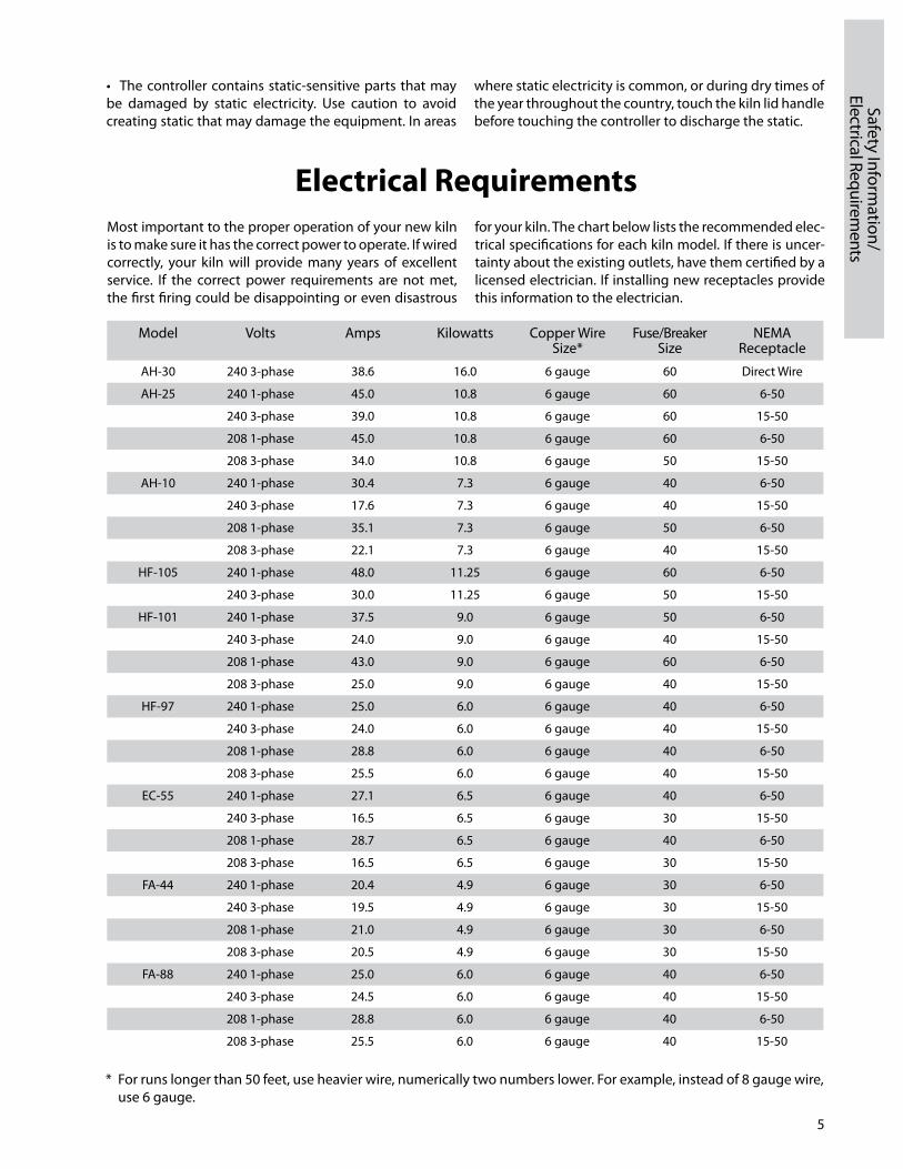
Electrical RequirementsMost important to the proper operation of your new kiln is to make sure it has the correct power to operate. If wired correctly, your kiln will provide many years of excellent service. If the correct power requirements are not met, the first firing could be disappointing or even disastrous
for your kiln. The chart below lists the recommended electrical specifications for each kiln model. If there is uncertainty about the existing outlets, have them certified by a licensed electrician. If installing new receptacles provide this information to the electrician.
Model Volts Amps Kilowatts Copper Wire Size*
Fuse/Breaker Size
NEMA Receptacle
AH30 240 3phase 38.6 16.0 6 gauge 60 Direct Wire
AH25 240 1phase 45.0 10.8 6 gauge 60 650
240 3phase 39.0 10.8 6 gauge 60 1550
208 1phase 45.0 10.8 6 gauge 60 650
208 3phase 34.0 10.8 6 gauge 50 1550
AH10 240 1phase 30.4 7.3 6 gauge 40 650
240 3phase 17.6 7.3 6 gauge 40 1550
208 1phase 35.1 7.3 6 gauge 50 650
208 3phase 22.1 7.3 6 gauge 40 1550
HF105 240 1phase 48.0 11.25 6 gauge 60 650
240 3phase 30.0 11.25 6 gauge 50 1550
HF101 240 1phase 37.5 9.0 6 gauge 50 650
240 3phase 24.0 9.0 6 gauge 40 1550
208 1phase 43.0 9.0 6 gauge 60 650
208 3phase 25.0 9.0 6 gauge 40 1550
HF97 240 1phase 25.0 6.0 6 gauge 40 650
240 3phase 24.0 6.0 6 gauge 40 1550
208 1phase 28.8 6.0 6 gauge 40 650
208 3phase 25.5 6.0 6 gauge 40 1550
EC55 240 1phase 27.1 6.5 6 gauge 40 650
240 3phase 16.5 6.5 6 gauge 30 1550
208 1phase 28.7 6.5 6 gauge 40 650
208 3phase 16.5 6.5 6 gauge 30 1550
FA44 240 1phase 20.4 4.9 6 gauge 30 650
240 3phase 19.5 4.9 6 gauge 30 1550
208 1phase 21.0 4.9 6 gauge 30 650
208 3phase 20.5 4.9 6 gauge 30 1550
FA88 240 1phase 25.0 6.0 6 gauge 40 650
240 3phase 24.5 6.0 6 gauge 40 1550
208 1phase 28.8 6.0 6 gauge 40 650
208 3phase 25.5 6.0 6 gauge 40 1550
* For runs longer than 50 feet, use heavier wire, numerically two numbers lower. For example, instead of 8 gauge wire, use 6 gauge.
6
Elec
tric
al R
equi
rem
ents
/ W
hen
Your
Kiln
Arr
ives
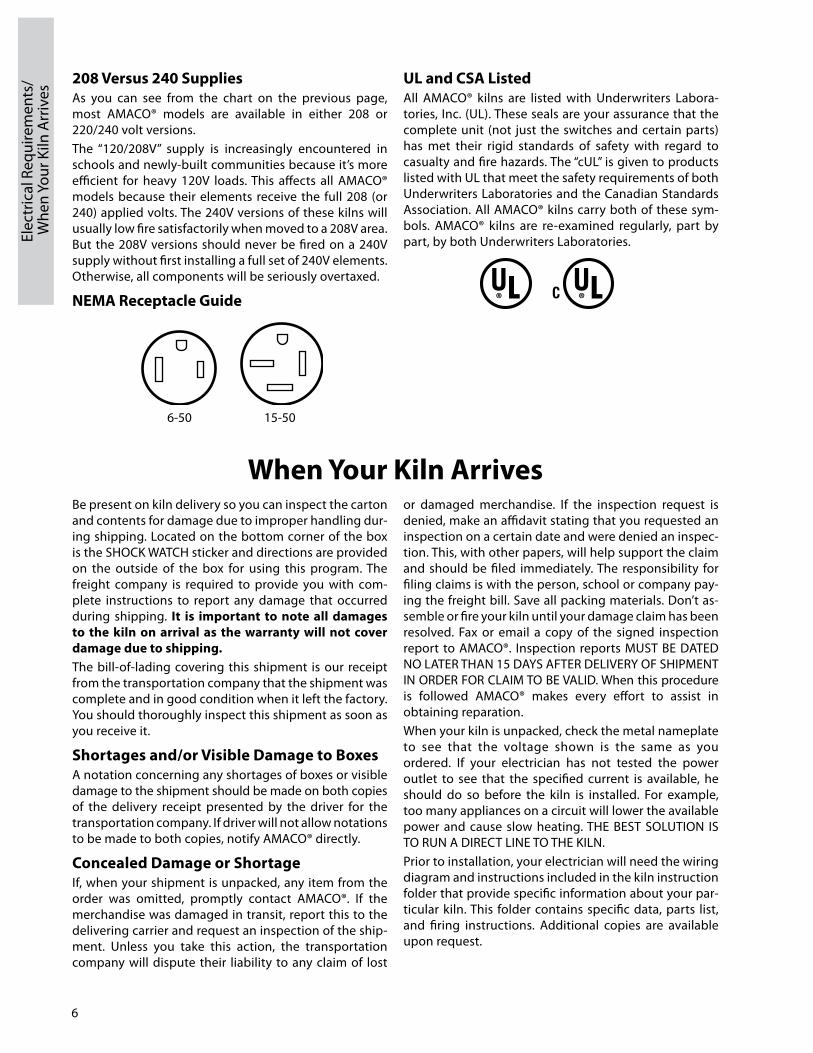
208 Versus 240 SuppliesAs you can see from the chart on the previous page, most AMACO® models are avail able in ei ther 208 or 220/240 volt ver sions.The “120/208V” supply is increasingly en coun tered in schools and newlybuilt com mu ni ties be cause it’s more efficient for heavy 120V loads. This affects all AMACO® models because their elements receive the full 208 (or 240) applied volts. The 240V versions of these kilns will usually low fire sat is fac to ri ly when moved to a 208V area. But the 208V ver sions should never be fired on a 240V supply with out first installing a full set of 240V elements. Oth er wise, all com po nents will be se ri ous ly overtaxed.
NEMA Receptacle Guide
UL and CSA ListedAll AMACO® kilns are listed with Underwriters Laboratories, Inc. (UL). These seals are your assurance that the complete unit (not just the switches and certain parts) has met their rigid standards of safety with regard to casualty and fire hazards. The “cUL” is given to products listed with UL that meet the safety requirements of both Underwriters Laboratories and the Canadian Standards Association. All AMACO® kilns carry both of these symbols. AMACO® kilns are reexamined regularly, part by part, by both Underwriters Laboratories.
650 1550
When Your Kiln ArrivesBe present on kiln delivery so you can inspect the carton and contents for damage due to improper handling during shipping. Located on the bottom corner of the box is the SHOCK WATCH sticker and directions are provided on the outside of the box for using this program. The freight company is required to provide you with complete instructions to report any damage that occurred during shipping. It is important to note all damages to the kiln on arrival as the warranty will not cover damage due to shipping. The billoflading covering this shipment is our receipt from the transportation company that the shipment was complete and in good condition when it left the factory. You should thoroughly inspect this shipment as soon as you receive it.
Shortages and/or Visible Damage to BoxesA notation concerning any shortages of boxes or visible damage to the shipment should be made on both copies of the delivery receipt presented by the driver for the transportation company. If driver will not allow notations to be made to both copies, notify AMACO® directly.
Concealed Damage or ShortageIf, when your shipment is unpacked, any item from the order was omitted, promptly contact AMACO®. If the merchandise was damaged in transit, report this to the delivering carrier and request an inspection of the shipment. Unless you take this action, the transportation company will dispute their liability to any claim of lost
or damaged merchandise. If the inspection request is denied, make an affidavit stating that you requested an inspection on a certain date and were denied an inspection. This, with other papers, will help support the claim and should be filed immediately. The responsibility for filing claims is with the person, school or company paying the freight bill. Save all packing materials. Don’t assemble or fire your kiln until your damage claim has been resolved. Fax or email a copy of the signed inspection report to AMACO®. Inspection reports MUST BE DATED NO LATER THAN 15 DAYS AFTER DELIVERY OF SHIPMENT IN ORDER FOR CLAIM TO BE VALID. When this procedure is followed AMACO® makes every effort to assist in obtaining reparation.When your kiln is unpacked, check the metal nameplate to see that the voltage shown is the same as you ordered. If your electrician has not tested the power outlet to see that the specified current is available, he should do so before the kiln is installed. For example, too many appliances on a circuit will lower the available power and cause slow heating. THE BEST SOLUTION IS TO RUN A DIRECT LINE TO THE KILN.Prior to installation, your electrician will need the wiring diagram and instructions included in the kiln instruction folder that provide specific information about your particular kiln. This folder contains specific data, parts list, and firing instructions. Additional copies are available upon request.

7
Kiln Location/Kiln Venting—
Why it is Im
portant
Kiln Location• Locate your kiln near your present electrical outlet or where a new circuit can be installed. Position the kiln to the left of your electrical outlet so the cord will have an easy run and will not place a strain on the plug or outlet.• Place the kiln in a room large enough to allow for adequate air flow and if the room is under 10' x 10', make sure there is a way for air to enter the room. • Install it in a well ventilated, sheltered area such as a garage, utility or hobby room. Allow a MINIMUM 18 INChES (46 cm) of space between your kiln and adjacent walls, other kilns, shelving, etc. When multiple kilns will be installed in the same room, make sure the control boxes on the kilns are not facing adjacent kilns. Radiant heat from nearby kilns can damage the controller.• In front loading kilns, make sure there is adequate space for a service technician to access the back of the kiln. Warranty service will not be covered by AMACO® if adequate space for repairs and a safe working environment is not provided for service technicians.• For small rooms, monitor the firing so room temperature does not exceed 100˚F (38˚C). Do not fire if room temperatures are 32˚F (0˚C) or less as damage to the electronic components may result. An example of a typical room layout is shown at right. • Locate the kiln in a room with a bare cement floor. If a bare cement floor is not available, the uniform mechanical code requires two inches of masonry below the kiln extending a minimum of 12" (31 cm) beyond the outside circumference of the kiln.
• Never fire your kiln within a four sided cabinet or closet. The fourth side must always be open to room air to prevent the kiln from overheating surrounding surfaces. It is best to leave at least two sides open for easy access to controls and peepholes.• When installing a kiln in a room with a fire control sprinkler system, do not place kilns within a 10 ft. (3m) radius below sprinkler heads. If this is not possible, contact AMACO® for alternative solutions before installing.• All kilns are vulnerable to the highly corrosive effects of marine air. If you live near salt water, locate the kiln indoors and protect it from the damp air.• Keep curtains, aprons, plastic or other flammable materals away from your kiln.
Safer Work Areas Successful firings and safe healthy work environments depend on clean circulated air in the kiln room as well and the firing chamber. It is recommended that all AMACO® kilns use a direct, down draft venting system like the Master KilnVent (all AMACO® kilns) or the KilnVent Suspended Version (top loading AMACO® kilns only). These systems take the fumes from the kiln chamber, mix them with room air and vent them to an outside source, insuring that the gasses do not reach the work area. The venting systems will not reduce the temperature in the kiln and actually improve the uniformity of the kiln firing by increasing the circulation inside the chamber. Cooldown time is reduced by 24 hours often allowing firing the very next day.Testing has shown that gasses generated by the use of unvented kilns exceed OSHA levels for carbon monoxide and should be removed from the kiln room. The AMACO® kiln vent systems effectively mix hot gas from the kiln
with room air to provide a cool exhaust that is safely vented outdoors. In addition to making the kiln room more comfortable, accidental burns and jarring of the ware are reduced because the lid stays closed throughout the firing.
Better Finished ResultsDown draft, direct venting systems produce truer colors, uniform firings and less glaze flaws. 1) Carbon monoxide is reduced while adding oxygen for reds, greens, gold and yellows. Colors are brighter and more vibrant and different colors can be fired at the same time. 2) Venting also produces more even firings and uniform colors by circulating the hot gasses. The items on the bottom of the kiln receive the same heat as items on the top. 3) Providing oxygen in the kiln chamber helps to burn out carbon and organic compounds in the clay body, reducing pinholes, glaze craters, and bubbles.
Kiln Venting—Why it is Important

8
Inst
allin
g th
e M
aste
r Kiln
Vent Installing the Master KilnVent
The Master KilnVent can be used for all AMACO® front and top loading square kilns to vent gasses from the kiln to the outside via flexible metal ducting. It can be mounted to both side, bottom or top of all AMACO® front loading kilns or in the center or bottom of all AMACO® top loading kilns.
A. High temperature hose with clamp B. Blower/motor with 6' power cord C. Connector cup D. Adjustable height foot/coupling nut/wing nut E. GasketNot shown—additional parts and tools required (not supplied with vent):(4) #10 3/4" sheet metal screws(4) #10 1" dry wall screws4" Dia. flexible metal ducting (60' maximum)6" or longer 1/4" diameter drill bit (use 10" long, 1/4" diameter drill bit for AH30)Electric drillFlat head screwdriverPhillips head screwdriverVacuum cleaner
1. AMACO® kilns are predrilled to accept the Master KilnVent.2. Place insulation piece provided in kit over connector cup and mount cup centered over hole configuration with 3/4" sheet metal screws. Screws will enter directly into metal outer shell of kiln.3. Connect high temperature hose to connector cup using hose clamps provided, with flat head screwdriver.4. Connect black high temperature hose to Master Kiln Vent motor/blower with hose clamps provided. IMPOR-TANT: Cover extra high temperature receptacle if not venting two kilns.5. Master KilnVent motor can be mounted to the wall, stored in underside of kiln stand or placed on top of kiln.6. If mounting Master KilnVent motor to wall, use 1" sheet rock or appropriate screws.7. Attach 4" ducting to motor exhaust receptacle using hose clamps (not provided) and vent to outside source or existing ducting if under 60 feet. DO NOT have more than four 90° bends in ducting.8. Vacuum any brick dust that was generated during drilling.
Note: While the AMACO® vents are key to creating safe work environments and better work, these systems will not reduce the kiln temperature or the ambient heat the kiln radiates into the room. The kiln room area must be adequately sized and exhausted to keep the space under 100°F during peak temperatures and at least 18 inches of clearance must exist around all sides of the kiln. Sprinkler systems in kiln area should be rated so that they will not trigger when the kiln is at peak temperature.
A
B C
DE

9
Installing the KilnVent—
Suspended Version
31⁄2"Rear View
8" Figure 1
4"
This KilnVent is primarily designed to be used with AMACO® top loading kilns. The unit is tightly suspended on the bottom of the kiln using the hooks and springs provided.
A. Plenum B. Blower/motor with 6' power cord C. Blower adapter D. (2) 6" drill bits (1/4" and 5/32" dia.) E. 4" flexible aluminum duct (8' long) F. (2) springs (8" and 15" long) G. (3) hooks and (3) 5/8" sheet metal screws H. 4" hose clamp
Preparing the Kiln Be sure that your kiln has been prepared by drilling ventilation holes according to the directions in your KilnVent owners manual.
Installing the Rear hooks (for spring)• Mark two points, 31/2" up from the bottom of the kiln and 4" right and left of the center of the kiln as shown in figure 1:
• Drill a hole in the metal using the smaller of the two drill bits provided (5⁄32")• Attach two of the hooks using the sheet metal screws provided.
Installing the Front hook (for spring)• Mark a point that is 35⁄32" up from the bottom of the kiln and centered left to right.• Drill a hole in the sheet metal using the small drill bit (5⁄32").• Attach the remaining hook using the sheet metal screw provided.
Attaching the KilnVentThe KilnVent comes with a long spring (15") and a short (8") spring.• Attach the short spring to the front of the metal plenum by hooking the open end of the spring into the small hole located at the bottom front. (See figure 2.)• Place the KilnVent assembly under the kiln with the motor to the rear and facing up. Locate it so the angle on the plenum will rest up against the rear of the kiln. The fiberglass gasket will be between the kiln and KilnVent. The gasket will provide a seal and minimize vibration of the kiln. Make sure the plenum is aligned so that the holes in the bottom of the kiln floor are over the opening in the KilnVent and gasket.• Attach one end of the long (15") spring to one of the hooks. Holding the plenum up against the kiln, pull the spring under the plenum and attach it to the other hook. (See figure 2).
• The front of the metal plenum should be under the kiln with the small (8") spring attached. If the spring is not attached to the metal plenum, do this now.
• Pull the spring and attach it to the hook on the front of the kiln.• Adjust the metal plenum at the rear so that it rests flush with the back and bottom of the kiln.• No gap should exist between the bottom of the kiln and the top of the metal plenum. It is important that the gasket around the plenum hole be flush against the kiln bottom. If it is not, call AMACO®. We can provide an adaptor kit which can seal up to 11⁄2".
Installing the Flexible DuctingPlace the clamp over the 4" dryer ducting and install the ducting on the KilnVent at the end of the output tube. The ducting should go on the outside of the tube adaptor. Use the clamp provided to hold the ducting in place. Install the dryer vent flap using the instructions provided
Figure 2
Back Sideof Kiln
Sheet Metal Screws and Hooks
Gasket
15" Spring
Plenum
8" Spring
Installing the KilnVent—Suspended Version
A
B
C
D
E
H
H G F

10
Inst
allin
g th
e Ki
lnVe
nt—
Susp
ende
d
Vers
ion/
Mul
tiple
Kiln
vent
Sys
tem
s
by the manufacturer and with attention to your local and state codes and regulations.Once the dryer flap vent is installed, carefully stretch the flexible aluminum ducting and clamp it to the flap vent tube. When stretching the ducting, avoid sharp 90° bends (gentle, 45º bends are recommended) and do not twist or compress the ducting. Up to 60' of ducting containing 4 bends may be safely used with no drop in static air flow at the duct exhaust point or reduction in draw at the kiln. Seal any connections or punctures with silicone sealant or wrap with duct tape.
Finishing InstallationAttach the Reminder Tag to your kiln on the switch box where it will always be seen before firing. Plug the Kiln
Vent into a standard 120V outlet. Operate the switch to check out blower operation.You are now ready for your first test firing. Refer to the kiln owner’s manual or KilnVent for recommendations using the test cones provided.
Note: While the AMACO® vents are key to creating safe work environments and better work, these systems will not reduce the kiln temperature or the ambient heat the kiln radiates into the room. The kiln room area must be adequately sized and exhausted to keep the space under 100°F during peak temperatures and at least 18 inches of clearance must exist around all sides of the kiln. Sprinkler systems in kiln area should be rated so that they will not trigger when the kiln is at peak temperature.
Installing Multiple KilnVent SystemsIf you have the Master KilnVent with Expansion Kit or more than one AMACO® KilnVent—Suspended Version, you can install them individually or connect each unit to a central duct to remove the gases. For best air flow, a 45° elbow should be used. The recommended central duct diameter is 6" for two KilnVent Systems, 8" for three or four systems, and 10" for five or six KilnVent Systems.
Two kiln ventilation systems can be vented to a single exhaust point using a “Y” adaptor. However, a damper should be installed in each duct line and left closed when that ventilation system is not in use. See illustration below:
8" central duct to outside
4" d
uct f
rom
Kiln
Vent
#1
45º elbow
4" d
uct f
rom
Kiln
Vent
#2
4" d
uct f
rom
Kiln
Vent
#3
closed damper
4" duct to outside
4" duct from KilnVent #1
"Y" adaptor
open damper
4" duct from
KilnVent #2

11
Getting Started/Test Firing
Getting StartedThis page is a memory aid, not a substitute to reading and understanding the manual.Activate the power source by plugging in the kiln or controller. After plugging in the kiln, the display will read WAIT for approximately 10 seconds while power is restored to the kiln. It will then switch to Idle Mode. In Idle Mode the display will flash the kiln temperature alternating with IdLE. Begin all programming in Idle Mode.Be sure the programmer is set to the right temperature scale before proceeding (Fahrenheit or Celsius).
Cone Fire ModeStep 1 – Press CONE FIRE.
Step 2 – Input PREhEAT time. Press ENTER.
Step 3 – Input Cone number. Press ENTER.
Step 4 – Input a SPEED. Press ENTER.
Step 5 – Input hOLD time. Press ENTER.
Step 6 – Press START.
Ramp hold ModeStep 1 – Press RAMP/hOLD.
Step 2 – Input the PROG number. Press ENTER.
Step 3 – Input the number of segments. Press ENTER.
Step 4 – Input the first heatng rate. Press ENTER.
Step 5 – Input the first temperature to reach. Press ENTER.
Step 6 – Input hOLD time. Press ENTER.
Step 7 – Repeat steps 4 through 6 until alarm flashes. Press ENTER.
Step 8 – Press START.
Important: To effectively use Ramp/Hold mode, it is imperative to understand heatwork theory. If you know the theory well, and if you have had experience with other programmable kilns or controllers, then the Quick Start instructions will be use ful.If not, please read the complete Ramp/Hold in struc tions beginning on page 16 and page 18 for de tails.The Ramp/Hold Mode can be used for all fir ing ap pli cations including glass and, in high fire kilns, por ce lain and stone ware. This op tion al lows you to cre ate your own pro files with up to six ramp and hold seg ments. A segment has three com po nents: heat ing rate, tem per a ture and hold. It is easy to pro gram. Be sure to see page 37 for in for ma tion on heat work.
Test FiringOnce appropriately installed, the kiln is ready for the test fire. Test firing is important to operation of the kiln as it will help to identify any installation errors that may have occurred, burn off the protective coating on the elements, and properly oxidize them to maximize their life.
Preparations before test fireVacuum out the kiln to remove dust and packing material that may be present from shipping. Prep all shelves. Wipe clean all new shelves with a damp sponge. Mix AMACO® Kiln Shelf Wash (supplied) with water, to the consistency of whole milk, then apply three even coats to shelves and let dry. Apply Kiln Shelf Wash to one side of the shelves and leave a ¼ margin from the outside edge of the shelf. Never use Kiln Shelf Wash on the interior of the kiln.
Test Firing Follow the loading guidelines on page 12 without ware. Place Orton Self Supporting cones on each shelf, staggering the placement to ensure full kiln temp test coverage.
Select Fire™ ModelsIf your kiln is equipped with the Select Fire™, refer to page 16 (Programming Cone Fire Mode) and program the kiln for a cone 04 medium speed test fire with no hold and no preheat. The kiln should complete firing in approximately 8 hours.
Models with Infinite Control SwitchesIf your kiln has infinite control switches and Dawson KilnSitter®/Limit Timer, refer to page (29) to complete a Cone 04 fast speed cone fire test which takes approximately 8 hours.Once the test fire is complete and kiln has cooled check that the cones have all bent correctly.Your kiln is now ready to fire work!

12
Load
ing
Tips
Loading TipsBalance the LoadWhen planning how to load your kiln, keep in mind that the center of the kiln is generally the hottest. Therefore, you will want to distribute the load with the larger, thicker pieces towards the middle and the smaller, thinner pieces towards the top and bottom. In addition, if half your load consists of small, heavy pieces and the other half is large, thinwalled pieces, don’t group them all in one section. Mix them so there is a balance of each type throughout the kiln.
Allow the Kiln to BreatheMany studios work with glazes that require oxygen to develope properly. Providing adequate space between pieces allows the kiln to “breathe”. If the firing chamber of your the is larger than 18" x 18", the recommended furniture kit will contain smaller (half ) shelves for staggered shelf configurations. Allowing a minimum ¼" gap between half shelves will increase the flow of oxygen in the firing chamber, especially when using a kiln vent system.
Allow for Proper Clearances Kilns lose most of their heat from the lid/door. Ideally, there should be at least two inches of space between the lid and the nearest piece. DO NOT SET PIECES DIRECTLY ON THE KILN FLOOR. Place a shelf on 1" posts on the floor of the kiln. For best results, ware should not be placed within 1" of an element. Large flat
pieces like plates should have their rims positioned between two elements. When using an AMACO® Kilnvent System, the vents or “peepholes” in the front of the kiln allow air to be drawn into the firing chamber. Avoid placing ware directly under one of these holes, as this could create flaws in the glaze.
DO NOT crowd the Kiln-Sitter® or ThermocoupleKeep shelves at least ¼" from the sensing rod, and ware at least ½" away. If your load should shift during firing there will be less danger of jamming the KilnSitter® or having ware resting against the thermocouple causing inaccurate temperature readings or damage to the ware.
DO NOT load damp ware into your KilnMake sure all the ware is bone dry before loading it into the kiln. It should feel close to room temperature—if it feels colder, water is still evaporating from it.
DO NOT Rush Take the time to properly load the kiln. Dropped ware or shelves can cause damage. Take special care to protect the bottom elements on kiln models that have them. Check each piece to insure that excessive glaze or an unsteady placement will not cause problems during the firing. A few extra minutes could save a lot of frustration.
Front Loading Kiln
Top Loading Kiln

13
Select Fire™ Control Features
Select Fire™ Control Features (if equipped)
Digital ReadoutShows prompts, messages and tem per a ture
throughout firing and cool down.
TouchpadSmooth surface pads are
easy to clean and have no moving parts.
Delay OptionLets you delay start of
firing for convenient operation.
AlarmYou can set alarm
to sound at any tem per a ture.
Cone Fire ModeLets you fire by simply
en ter ing the desired Cone number.
Firing SpeedsChoose from Slow,
Medium or Fast heat ing.
ReviewReviews your current
firing program.
MenuLets you accesses menu diagnostics feature and advanced settings.
Action ControlsLets you start or stop kiln operation.
Ramp/hold ModeLets you select up to eight segments of tem per a ture change and hold.
View Current SegmentShows you what Ramp/Hold segment the kiln is currently in.
Cone TableConverts Cone numbers to temperature.
14
Prog
ram
min
g
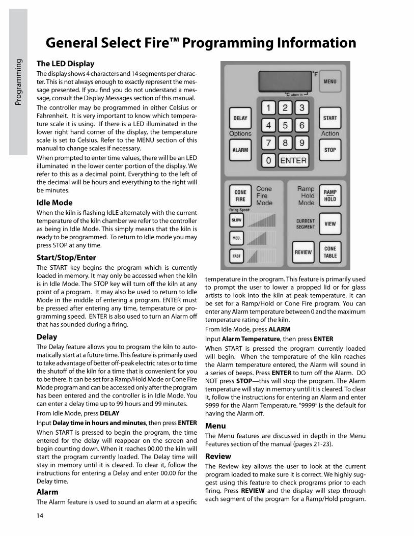
General Select Fire™ Programming InformationThe LED DisplayThe display shows 4 characters and 14 segments per character. This is not always enough to exactly represent the message presented. If you find you do not understand a message, consult the Display Messages section of this manual.The controller may be programmed in either Celsius or Fahrenheit. It is very important to know which temperature scale it is using. If there is a LED illuminated in the lower right hand corner of the display, the temperature scale is set to Celsius. Refer to the MENU section of this manual to change scales if necessary.When prompted to enter time values, there will be an LED illuminated in the lower center portion of the display. We refer to this as a decimal point. Everything to the left of the decimal will be hours and everything to the right will be minutes.
Idle ModeWhen the kiln is flashing IdLE alternately with the current temperature of the kiln chamber we refer to the controller as being in Idle Mode. This simply means that the kiln is ready to be programmed. To return to Idle mode you may press STOP at any time.
Start/Stop/EnterThe START key begins the program which is currently loaded in memory. It may only be accessed when the kiln is in Idle Mode. The STOP key will turn off the kiln at any point of a program. It may also be used to return to Idle Mode in the middle of entering a program. ENTER must be pressed after entering any time, temperature or programming speed. ENTER is also used to turn an Alarm off that has sounded during a firing.
DelayThe Delay feature allows you to program the kiln to automatically start at a future time. This feature is primarily used to take advantage of better offpeak electric rates or to time the shutoff of the kiln for a time that is convenient for you to be there. It can be set for a Ramp/Hold Mode or Cone Fire Mode program and can be accessed only after the program has been entered and the controller is in Idle Mode. You can enter a delay time up to 99 hours and 99 minutes.From Idle Mode, press DELAYInput Delay time in hours and minutes, then press ENTER When START is pressed to begin the program, the time entered for the delay will reappear on the screen and begin counting down. When it reaches 00.00 the kiln will start the program currently loaded. The Delay time will stay in memory until it is cleared. To clear it, follow the instructions for entering a Delay and enter 00.00 for the Delay time.
AlarmThe Alarm feature is used to sound an alarm at a specific
temperature in the program. This feature is primarily used to prompt the user to lower a propped lid or for glass artists to look into the kiln at peak temperature. It can be set for a Ramp/Hold or Cone Fire program. You can enter any Alarm temperature between 0 and the maximum temperature rating of the kiln.From Idle Mode, press ALARMInput Alarm Temperature, then press ENTER When START is pressed the program currently loaded will begin. When the temperature of the kiln reaches the Alarm temperature entered, the Alarm will sound in a series of beeps. Press ENTER to turn off the Alarm. DO NOT press STOP—this will stop the program. The Alarm temperature will stay in memory until it is cleared. To clear it, follow the instructions for entering an Alarm and enter 9999 for the Alarm Temperature. “9999” is the default for having the Alarm off.
MenuThe Menu features are discussed in depth in the Menu Features section of the manual (pages 2123).
ReviewThe Review key allows the user to look at the current program loaded to make sure it is correct. We highly suggest using this feature to check programs prior to each firing. Press REVIEW and the display will step through each segment of the program for a Ramp/Hold program.

15
Programm
ing
It will also let you know if there are Alarm temperatures or Delay times entered and whether or not the Error Codes feature is ON or OFF. Below is a sample Review of a Cone Fire program.Sample Cone Fire Review1. Cone 04 Cone Number2. F 1920 Actual temperature when kiln shut off3. SPD FAST Cone fire speed4. HOLD 0.00 Length of hold at top temperature5. PRHT 0.00 Preheat time (Will only be displayed if
preheat is set to ON)6. DELA 0.00 Delay Time 7. ALRM 9999 Alarm Temperature8. ERCD ON Error Codes On or Off
ViewThe View key allows you to determine what segment of a Ramp/Hold program the controller is currently running. While a Ramp/Hold program is firing press VIEW. The display will show the current segment, the traveling set point, and the circuit board temperature. The segment number is prefixed by either “RA” (Rate) or “HLd” to indicate whether the kiln is heating (or cooling) or holding temperature. The traveling setpoint indicates the target temperature of that segment.
Cone TableThe Cone Table key allows the user to look up the temperature equivalent of Cone values. To use simply press Cone Table from Idle Mode, enter a cone value and press ENTER . This key may also be used to insert a Cone Value for the peak temperature of a Ramp/Hold program. This Cone Value will be automatically adjusted (Cone Correlation) based on the performance of the kiln. To use this feature press Cone Table when prompted to enter the peak temperature of your program, enter a Cone value and press ENTER.
During the Firing You will see the internal temperature of the kiln displayed as the temperature increases. The options available during the firing are:• Review program at any time.• View Current Segment of RAMP/hOLD Program.• Press Stop to interrupt a firing for any reason.Note: It is common to see smoke come out of your kiln on the first firing. This is normal; the elements are burning off a coating.
After the Firing • When completed, the display will show “CPLt” alternately with the firing time in hours and minutes and the current temperature of the kiln. Press ENTER to return to Idle Mode.
• When a Cone Fire Mode program (or a Ramp/Hold program which uses the Cone Correlation feature) is run, the controller may alter the peak temperature of the program based on the kilns ability to achieve the final temperature rate. This is done to insure the heatwork remains constant. If you are interested in knowing if that temperature changed, press REVIEW after the program is complete. This temperature value will only appear in a review once after the firing so be sure to pay attention.• Allow the kiln to cool naturally. Never unplug additional peepholes or post the lid until the ware is cool enough for barehanded unloading, about 130˚F (54˚C).• When unloading, be sure to examine the self-supporting cones on the shelf to determine if the kiln is firing correctly.• It is not necessary to unplug the kiln when not in use (unless severe storms are expected). Continuous plugging and unplugging may cause components in the plug and receptacle to loosen up over time. Loose components in electrical connections create heat and can pose a fire hazard.
Fine Tuning Your KilnIf after inspecting your witness cones you find that the kiln fired a little hot, a little cold, or a little uneven, there are certain things you can do to fine tune the kiln before your next firing. Always be sure you use self supporting 108˚F (42˚C) witness cones. Cones should be placed about 2 inches (4.8 cm) from the kiln wall and or thermocouple. Never place cones directly on the bottom slab.
Too CoolAdd more Hold Time to a Cone Fire program. If the target cone did not bend at all, try adding 15 minutes to the Hold Time. If the Cone has started to bend, add time in 5 minute increments. If hold times begin exceeding 30 minutes contact AMACO® or your distributor for more information.
Too hotIf the Cone is knuckled down on the shelf, reduce the Hold Time by 15 minutes. If the tip of the Cone has just started to touch the shelf, reduce Hold Time in 5 minute increments. If hold times are already set to zero, contact AMACO® or your distributor for more information. Thermocouples drift towards an over fire as they age so if the problem persists or requires excessive changes to correct, it may be time to change the thermocouple.
Uneven heat DistributionVenting systems such as the AMACO® Master KilnVent or KilnVent—Suspended Version help with uneven heating by mixing the air within the kiln chamber.

16
Prog
ram
min
g
Choosing a ProgramThe first step in programming your kiln is to decide which “Programming Mode” to use. Before making this decision it helps to have a good understanding of Firing Programs. A Firing Program consists of a series of program segments. Each segment consists of a Rate, a Temperature and a Hold Time. These segments determine the rate at which the kiln will heat up or cool down and how much Heatwork the pieces in the kiln will receive. For more information on Heatwork see page 37.
Cone Fire ModeWith Cone Fire Mode the programs are written for you. You simply give the controller some key information regarding the pieces you are firing and it accesses a program which best suits your project. This is the most commonly used mode of programming. The programs were created by Ceramic Engineers and are designed to minimize problems that can occur during critical stages in the firing process.Cone Fire Mode is incredibly easy to use however, the software itself is extremely advanced. Cone Fire Mode uses complex algorithms to simulate the heatwork of a Pyrometric Cone. What is impressive is that it automatically makes adjustments to the firing profile based on your kiln's performance. Cone values are based on heatwork and heatwork is a function of time and temperature. Therefore, if your kiln is firing slow due to a heavy load or aging elements, Cone Fire Mode automatically adjusts the peak temperature down so you get the perfect amount of heatwork. There are very few reasons not to use this mode of programming.
RAMP/hOLD ModeRAMP/HOLD Mode allows you to write your own programs when the results you want cannot be achieved through Cone Fire Mode. It is a perfect tool for:• Fusing and slumping glass• Annealing metal and glass• Firing Precious Metals • Clay• Specialized glaze formulations and techniquesRamp/Hold is generally considered an advanced form of programming. It requires indepth knowledge of heatwork and a good feel for how your kiln performs under a range of conditions. Below is an example of a simple glass fusing Ramp/Hold program.
Programming Cone Fire ModeProgramming StepsStep 1 – From Idle Mode. Press CONE FIRE. Display will read PRHT alternately with 00.00.
Step 2 – Input a PREhEAT TIME IN hOURS AND MIN-UTES. Press ENTER. (See page 23 for more information on Preheat.) Display will read CONE alternately with the last Cone Value entered.
Step 3 – Input a CONE VALUE. Press ENTER. Display will read Spd alternately with the last Speed entered.
Step 4 – Press a SPEED (SLOW, MED or FAST). Press ENTER. Display will read HOLD alternately with a Hold time value.
Step 5 – Input a hOLD TIME if one is desired. Press ENTER. Display will flash CPL, then will return to Idle
Mode. At this point the program is loaded and ready to start. Before pressing START, it is a good idea to press REVIEW to make sure the program was input correctly. Also, verify that the lid latch is engaged if your kiln is equipped with a lid lifter and check to see the area is clear of all combustible materials.
Step 6 – Press START. Display will read ON briefly and then display the current temperature of the kiln. If a delay start has been entered the display will begin counting down the time entered.When the firing is complete the display will read CPLT alternately with the current temperature of the kiln and the time it took to complete the program. To clear this data and return to Idle Mode, press ENTER.
17
Programm
img
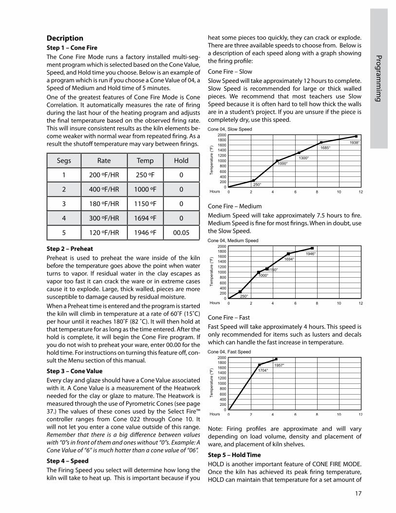
DecriptionStep 1 – Cone Fire The Cone Fire Mode runs a factory installed multisegment program which is selected based on the Cone Value, Speed, and Hold time you choose. Below is an example of a program which is run if you choose a Cone Value of 04, a Speed of Medium and Hold time of 5 minutes.One of the greatest features of Cone Fire Mode is Cone Correlation. It automatically measures the rate of firing during the last hour of the heating program and adjusts the final temperature based on the observed firing rate. This will insure consistent results as the kiln elements become weaker with normal wear from repeated firing. As a result the shutoff temperature may vary between firings.
Step 2 – Preheat Preheat is used to preheat the ware inside of the kiln before the temperature goes above the point when water turns to vapor. If residual water in the clay escapes as vapor too fast it can crack the ware or in extreme cases cause it to explode. Large, thick walled, pieces are more susceptible to damage caused by residual moisture.When a Preheat time is entered and the program is started the kiln will climb in temperature at a rate of 60˚F (15˚C) per hour until it reaches 180˚F (82 ˚C). It will then hold at that temperature for as long as the time entered. After the hold is complete, it will begin the Cone Fire program. If you do not wish to preheat your ware, enter 00.00 for the hold time. For instructions on turning this feature off, consult the Menu section of this manual.
Step 3 – Cone ValueEvery clay and glaze should have a Cone Value associated with it. A Cone Value is a measurement of the Heatwork needed for the clay or glaze to mature. The Heatwork is measured through the use of Pyrometric Cones (see page 37.) The values of these cones used by the Select Fire™ controller ranges from Cone 022 through Cone 10. It will not let you enter a cone value outside of this range. Remember that there is a big difference between values with “0”s in front of them and ones without “0”s. Example: A Cone Value of “6” is much hotter than a cone value of “06”.
Step 4 – SpeedThe Firing Speed you select will determine how long the kiln will take to heat up. This is important because if you
heat some pieces too quickly, they can crack or explode. There are three available speeds to choose from. Below is a description of each speed along with a graph showing the firing profile:
Cone Fire – Slow Slow Speed will take approximately 12 hours to complete. Slow Speed is recommended for large or thick walled pieces. We recommend that most teachers use Slow Speed because it is often hard to tell how thick the walls are in a student’s project. If you are unsure if the piece is completely dry, use this speed.
Cone Fire – MediumMedium Speed will take approximately 7.5 hours to fire. Medium Speed is fine for most firings. When in doubt, use the Slow Speed.
Cone Fire – FastFast Speed will take approximately 4 hours. This speed is only recommended for items such as lusters and decals which can handle the fast increase in temperature.
Note: Firing profiles are approximate and will vary depending on load volume, density and placement of ware, and placement of kiln shelves.
Step 5 – hold TimeHOLD is another important feature of CONE FIRE MODE. Once the kiln has achieved its peak firing temperature, HOLD can maintain that temperature for a set amount of
Segs Rate Temp Hold
1 200 ºF/HR 250 ºF 0
2 400 ºF/HR 1000 ºF 0
3 180 ºF/HR 1150 ºF 0
4 300 ºF/HR 1694 ºF 0
5 120 ºF/HR 1946 ºF 00.05

18
Prog
ram
min
g
time. This allows the user to make fine tune adjustments to the firing process by introducing more heatwork which can help witness cones reach maturity. Additionally, a HOLD permits the kiln to equalize temperature, allowing for even firings and firings that fall between cone temperatures, for example Cone 05.5.
CAUTION: Excessive hold time can result in over firings. A common mistake is to enter ten hours when a tenminute
hold is desired. 00.10 equals ten minutes, 10.00 equals ten hours.Step 6 – StartStart initiates the CONE FIRE MODE firing program. If a Delay is entered the kiln will start a countdown from the amount of entered delay time. Before pressing START, verify that the lid latch is engaged, and that all combustible materials are moved out of the vicinity.
Advanced Cone Fire Menu FeaturesIn Cone Fire Mode, the operator has the ability to modify the firing program. They can do this in one of two ways. The first method allows the user to program custom Cone Fire programs. The second involves controlling the rate in which the kiln cools down.
Writing Custom Cone Fire ProgramsThis new feature on the 700 Board allows you to utilize the cone correlation benefits of Cone Fire Mode coupled with the flexibility of RAMP/HOLD Mode. To use Cone Correlation to calculate your final temperature during a RAMP/
HOLD program press CONE TABLE instead of entering a temperature for your final heating segment. Input the Cone Value you would like to correlate and Press ENTER.
Slow Cooling (Cone Fire Controlled Cooling) COOL is a feature that allows you to add a 1segment cooling program to the end of a Cone Fire program. When COOL is toggled “ON” it will prompt you to enter a “Rate”, “Temperature”, and “Hold Time” after you finish entering the Hold Time for a Cone Fire program. This is helpful when trying to achieve certain glaze effects.
Programming the Ramp/hold ModeProgramming StepsStep 1 – From Idle Mode, press RAMP/hOLD. Display will show PROG alternating with a number between 1 and 6.
Step 2 – Input the PROG Number of the Program you wish to create or run. (This is a number between 1 and 6 that you assign to a program which will be stored in permanent memory until it is replaced.) Press ENTER. Display will show SEGS.
Step 3 – Input the total number of segments for your program. Press ENTER. Display will show RA 1.
Step 4 – Input the first heating rate in degrees per hour. Press ENTER. Display will show ˚F 1 (or ˚C 1 if using Celsius).
Step 5 – Input the first temperature to reach. Press ENTER. Display will show HLD 1.
Step 6 – Input the amount of hold Time in hours and minutes. Press ENTER. Display will show ALRM if this is the last segment you are entering, otherwise it will show RA 2.
Step 7 – Repeat steps 4 through 6 until all segments have been completed. The display will then flash ALRM (Alarm) alternately with the current Alarm temperature. The default setting for no alarm is 9999. Enter the desired alarm setting. Press ENTER. Display will briefly flash CPL.
Step 8 – Prepare Venting (See description on pages 810.)
Step 9 – The display will return to Idle mode. At this point the program is loaded and ready to start. Before pressing START, it is a good idea to press REVIEW to make sure the
program was input correctly. Be sure to check that the lid latch is secure on kilns that are equipped with lid lifters. Press START and the program will begin firing.Display will briefly show ON and then will show the internal temperature of the kiln chamber unless a DELAY START has been programmed in which case it will begin counting down minutes from the designated delay time.
DescriptionStep 1 – RAMP/hOLDRamp/Hold Mode is a mode of programming that allows you to write your own firing program. When you are entering your program you will notice data already stored. Simply write over this information. If you misenter data you may either press zeros to clear the data and reenter it or press STOP to start from the beginning.
Step 2 – Program Number (PROG)You have the option of storing up to six firing programs. You may recall these programs at any time for future use. We recommend that you write down which number you have assigned each program so that you do not overwrite existing programs you have stored.
Step 3 – Segments (SEGS)This step is prompting you to input the total number of segments you wish to use in your program. Each segment consists of a heating or cooling rate, a target temperature, and a hold time at that target temperature if one is desired. You may program up to eight

19
Programm
ing
segments. Two programs may be connected to achieve 16 segment programs. See instructions below.
Step 4 – Rate (RA#) This step is prompting you to input a Temperature Rate. The display will show RA along with the current segment number you are programming alternately with the previous data entered. You may enter any rate between 1ºF/hr (1ºC/hr) to 9999ºF/hr (9999ºC/hr). This can be a cooling rate or a heating rate. The controller distinguishes between the two by checking to see if the temperature entered in the next segment is hotter or cooler than the previous segment.Just because you enter a rate does not mean the kiln is capable of achieving that rate. Things such as element age, load density, and temperature range will all affect the kilns ability to heat. Conversely, the kiln’s insulation will influence its ability to cool. A rate must be entered for each segment.
Step 5 – Temperature (ºF#) or (ºC#)This prompt is asking you to enter a temperature to go to. When it gets to that temperature it will either hold at that temperature or switch to a new rate and aim for a new temperature. If you are programming in Celsius it will read ºC instead of ºF. The controller will allow you to program temperatures between 32ºF (0ºC) and 2400ºF (1315ºC). A temperature should not be entered which exceeds the kilns temperature rating.
Step 6 – hold Time (hOLd)A HOLD time is generally entered to allow the kiln time to balance out and all of the pieces in the kiln to reach the input temperature before the kiln moves to the next segment. You may enter hold times of 00.00 to 99.99. A Hold at peak temperature can be used for this reason or to gain additional heatwork to fine tune cone bends or to fire inbetween cones. Remember that everything to the left of the decimal point on the display is Hours and everything to the right is Minutes. Excessive Hold times may cause overfires.
Step 7 – RepeatContinue to enter a rate, a temperature, and a hold time for all the segments. When the last segment has been entered the display will prompt you to enter an Alarm temperature. The default is 9999 for no alarm. Input an Alarm temperature and Press ENTER. The display will briefly flash CPL for “complete” and then return to Idle Mode. The program is now loaded.
Steps 8 and 9 – Prepare venting and StartBefore starting the program it is always a good idea to press REVIEW and make sure the data was entered correctly. If you find an error simply press RAMP/HOLD and continue to press ENTER until you find the error and are able to correct it. If there is a Delay entered, when you press start the kiln will begin counting down from the input time. Remember to turn on your vent before pressing START.
Advanced Features16-SegmentWhen the 16Segment feature is toggled ON, the controller links programs #5 and #6. Now, when you run program #5, it will automatically run program #6 to continue the firing after program #5 has completed. Due to requirements of the software, the first segment of Program #6 must be increasing in temperature. Here is how to use this feature:
Step 1 – Input a 1 to 8 segment RAMP/HOLD Program in PROG #5.
Step 2 – Input a 1 to 8 segment RAMP/HOLD Program in PROG #6.
Step 3 – Press RAMP/hOLD, press 5. Press ENTER. Press STOP.
Step 4 – Press MENU. The Display will show SET. Press ENTER. The Display will show PRHT. Press MENU until the display shows 16S then press ENTER. The display will show OFF. Toggle to ON using the 1 key, then press ENTER.
Step 5 – Press REVIEW. Press START. IMPORTANT: Program #5 must be cued prior to toggling the feature, ON. Once both programs have run, the controller automatically toggles OFF the 16segment feature.
Skip StepSkip any segment in a Ramp/Hold Program by pressing VIEW quickly followed by pressing ENTER. If done quick enough you will see SKIP in the display. Immediatly press ENTER again.
Cone CorrelationThe 700 Board allows you to utilize the cone correlation benefits of CONE FIRE Mode coupled with the flexibility of RAMP/hOLD Mode. To use Cone Correlation to calculate your final temperature during a RAMP/HOLD program, press CONE TABLE instead of entering a temperature for your final heating segment. Input the Cone Value you would like to correlate and press ENTER.

20
Prog
ram
min
g/M
enu
Tree
Select Fire™ Menu Tree
Running a Stored Ramp hold ProgramStep 1 – Press RAMP/hOLD.
Step 2 – Input disired stored program number.
Step 3 – Press STOP.
Step 4 – Press REVIEW.
Step 5 – Press START.

21
Menu Features
New FeaturesAmong other changes, the 700 Board in the Select Fire™ controller has the ability to do selfdiagnostics. It can now show the voltage and amperage directly from the display, eliminating the need for expensive test equipment or having to hire a technician. Look through the entire MENU selection to become familiar with the options available to you.
New Menu LayoutWith the exception of the new green 14segment LED display, you will notice that the board and all of the function keys look exactly the same. All of the changes have been made in the MENU key. There are now four option headings under the MENU key. They are:
• SET Settings• dIAG Diagnostics• CNFG Configurations• Other – – – –
Menu Programming TipsTo access the Menu Headings, press MENU. You can toggle though the Menu Headings by continuing to press the MENU key. When you reach the one you wish to access press ENTER This will take you to the first option in that submenu. As before, if you want to toggle through the various options under the selected Heading, press MENU. When you reach the option you wish to access, press ENTER.When you select an option, you are asked to either:• Toggle the option ON/OFF• Input a value• Choose a valueTo toggle options ON/OFF, press 1. When you get to the desired setting, press ENTER.To Input a value such as a Delay time or an Alarm temperature, input the value and press ENTER.To select a value, press the MENU key until your selection is displayed, and then press ENTER.
Programming InstructionsSET (Settings) SET, is where all of the commonly used options are located. The following options are available under the SET heading menu:
PRhT (Preheat)This feature allows you to toggle the Preheat feature ON or OFF. The Preheat feature allows you to Input an amount of time to hold at 180˚F (82˚C) prior to running a CONE FIRE Program. This feature is recommended when firing large, thickwalled, or potentially damp ware. When the feature is toggled ON, it will prompt you to input a hold time value after the CONE FIRE key is pressed.
COOL (CONE FIRE Controlled Cooling)This feature allows you to add a 1segment cooling program to the end of a CONE FIRE program. When it is toggled “ON”, it will prompt you to input a “Rate”, “Temperature”, and “Hold Time” after you input the Hold Time for a CONE FIRE program. This is helpful when trying to achieve certain glaze effects.
ChG ° (Change from Fahrenheit to Celsius Scale) The controller can display temperature values in Fahrenheit or Celsius. If the scale is set to display in Celsius an LED dot will illuminate in the bottom right hand corner of the display. To select a new scale, press ENTER, and it will automatically toggle to the alternate scale. “ °C ” represents Celsius and “ °F “ represents Fahrenheit.
16-S (16-Segment) This option links the RAMP/HOLD programs stored in memory positions 5 and 6 to create a 16segment pro
gram. Normally a program is limited to 8 segments. This feature will only display when a CONE FIRE Mode program or the number 5 Ramp/Hold program is loaded. See page 19 for programming instructions.
dIAG (Diagnostics)“dIAG” or Diagnostics, is where all of the diagnostic tools are located. The following options are available under the “dIAG” menu:
ERTF (Err Temp & Time of Last Firing)This feature will display the temperature and the point of time in the firing at which the last Error occurred. This information is helpful in troubleshooting the problem which created the error. Once “ERTF” is selected, it will first flash the temperature at which the error occurred and then the time into the firing it occurred. The ERTF information will also appear automatically when an error alarm sounds and the program is terminated. Pressing any key, will show the temperature and elapsed time at which the error occurred.
VOLT (Voltage)This feature is used to test the voltage supply to your kiln. It tests the voltage first with the elements off , “No Load” and then again with the kiln on, or “Full Load”. Select “VOLT” from the “dIAG” menu and press ENTER. After the “NOLd” reading is displayed, press ENTER to receive the “FLLd” reading. The power to the kiln will be switched on for a brief moment when the voltage under load is checked. Our technicians can use this information to help you troubleshoot voltage related problems over the phone. When the voltage readings appear on your display, write
22
Men
u Fe
atur
es
them down. Often times voltage related problems can happen only at certain times of day, so try to obtain the readings at the same general time your kiln would be firing.
AMPS (Amperes) This is probably the most useful diagnostic tool available to you. All Select Fire™ controllers produced after 3/20/2006 are equipped with a current sensor in the control box. This allows us to test the current of each output to the kiln. This is very helpful in determining if a relay or element needs replacing.When you select “AMPS” under the “dIAG” menu, it will give you an ampere reading for each output of the kiln (except the accessory and safety output). Which elements these outputs control will vary by model. If your kiln uses only one or two outputs it will still give you three readings but the unused outputs will give a reading of zero.
LEd (LED Display)This feature, when activated, lights up all of the segments in the LED display. This is helpful in locating any segments in the display that may have gone bad and may explain why some indicated readings are not correct.
bd T (Board Temperature)The electronics on the controller’s circuit board may be damaged if the board exceeds 160˚F (71˚C). This should not occur under normal conditions. However, if the kiln is located in a small enclosure with poor ventilation or in areas where the temperatures are unusually hot, it is possible. Using this feature will tell you if your controller temperature is approaching potentially harmful levels.If you find that your board temperature is consistently over 150˚F (65˚C), you may want to consider improving air circulation to the kiln room. A box fan blowing on the controller can help considerably.
SW V (Software Version) At AMACO®, we are continually working on ways of improving our products. This feature will indicate the software version your controller is using.
OUTS (Output Test) There are four outputs that can be used on the board. There are three designated for elements and one designated to run an accessory. This feature allows you to test each output individually to see if it is operating correctly.When activated this feature will test each output beginning with Output 1 and ending with Output 4. It will cycle each output on for approximately two minutes. You can advance to the next output at any time by pressing ENTER. To see if the elements are cycling ON, you can place a small piece of paper on each element. If the paper is burned, then the element came on. Important: Be sure that the control box and kiln lid are closed before you use this feature in order to avoid electrical shock. CNFG (Configuration)Caution: Be sure to consult with an AMACO® technician before making any configuration setting changes. Unadvised changes can cause permanent damage to your kiln and the ware inside it.
“CNFG” or Configuration, is where all of the controller configuration tools are located. The following options are available under the “CNFG” menu:
ERCd (Error Codes ON/OFF) Error codes are designed to help protect you, your kiln, and your ware when something goes wrong with the firing. There are times however, where you may wish to try a new technique which would trigger an error code under normal conditions. When error codes are turned off, the following codes are disabled:Error 1 - Terminate firing when kiln temperature is increasing at a rate slower that 12˚F (11˚C)/hr.Error 2 - Kiln Temperature 50˚F (10˚C) degrees above hold temperature.Error 3 - Kiln Temperature 50˚F (10˚C) degrees below hold temperature.Error 4 - Kiln Temperature 50˚F (10˚C) degrees above previous hold when ramping down. Error 5 - Kiln Temperature 50˚F (10˚C) degrees below traveling set point when ramping down. Error D - Kiln Temperature 50˚F (10˚C) degrees above traveling set point.
TCOS (Thermocouple Offset) This feature allows you to calibrate the thermocouple when it is reading consistently and predictably incorrect. It is extremely important to consult with an AMACO® technician before making thermocouple offset adjustments. Incorrect adjustments to the thermocouple offset can cause permanent damage to your kiln. Adjustments made to the thermocouple offset will affect all RAMP/hOLD and CONE FIRE programs.If you are experiencing problems with CONE FIRE Mode, check to see if the ending temperature and hold time of the programs you are running have not been significantly altered from the factory programs before making thermocouple offset adjustments.Access the TCOS setting through the CNFG menu. The display will flash °F0S alternately with the current offset setting. °F0S represents degrees Fahrenheit Offset. If the controller was programed to display in Celsius, the “F” would be replaced by a “C”. If there is currently an offset input, this could be the problem. To be safe, make adjustments in small increments and then run a test fire with SelfSupporting Cones.To Make The Kiln Fire Cooler – Input 00 followed by the number of degrees you wish to offset the thermocouple.Press ENTER. Example: “0010” makes the kiln fire 10 degrees cooler.To Make The Kiln Fire hotter – Input 90 followed by the number of degrees you wish to offset the thermocouple.Press ENTER. Example: “9010” makes the kiln fire 10 degrees hotter.
Id (Control Interface System ID) CIS is an optional accessory that allows you to program and monitor multiple kilns from a PC. Each kiln hooked up to the CIS system needs to be identified with a unique number so the software can distinguish it from the oth

23
Menu Features
er kilns. To set the identifying CIS number for each kiln access the “Id” setting through the “CNFG” menu, select a number between 1 and 99 and press ENTER.OUT4 (Output 4 Settings) There are three standard outputs, one safety output and one accessory output on your Select Fire™ controller. The accessory output is designated as Output 4 and can control a number of optional accessories including vents, alarms and autodialers. Output 4 will cycle these accessories on and off at different times depending on the program you are running and the way you configure it under the “OUT4” feature setting. There are five different options for OUT4.Note: “ALR4” is the factory default setting. When you access the Output 4 feature the feature options will appear in the order listed below. The first option listed is not necessarily the current setting.
ALR4 (Alarm 4) This is the factory default setting. If Output 4 is not being utilized this is the setting that should be selected. This feature can also control an external alarm or autodialer to initiate if an Error Code is generated or if the internal temperature of the kiln reaches the temperature programmed for the ALARM setting of the program. To deactivate the alarm press ENTER.
PCT (Percent On) Output 4 is an auxiliary output used for accessories that need to be linked to the computer. Contact AMACO® technical services for more information.OP A (Option A) When option A is selected Output 4 will turn on when a CONE FIRE Mode program is started. When the program has run and the kiln has cooled to 150˚F (65˚C), output 4 will turn off. When a RAMP/HOLD program is inputted it will ask whether you want the fan (or other accessory) on for each segment you program. After you Input the hold time for each segment the display will show “FAN” along with the number of the segment you are programming. Alternately it will flash the current setting, either “OFF” or “ON”. To change the setting toggle it with the 1 key and press ENTER to select that setting.OP b (Option B) During a CONE FIRE program Output 4 will turn on when START is pressed. It will then turn off at 1450˚F (788˚C). It will turn back on when the kiln is cooling and the temperature drops below 1000˚F (538˚C). It will then turn off when the kiln cools to 150˚F (65˚C).When a RAMP/HOLD program is inputted it will ask whether you want the fan (or other accessory) on for each segment you program. After you Input the hold time for each segment the display will show “FAN” along with the number of the segment you are programming. Alternately it will flash the current setting, either “OFF” or “ON”. To change the setting toggle it with the 1 key and press ENTER to select that setting.
OP C (Option C) When Option C is selected Output 4 does not come on during any portion of a CONE FIRE Mode program.When a RAMP/HOLD program is inputted it will ask whether you want the fan (or other accessory) on for each segment you program. After you Input the hold time for each segment the display will show “FAN” along with the number of the segment you are programming. Alternately it will flash the current setting, either “OFF” or “ON”. To change the setting toggle it with the “1” key and press ENTER to select that setting.
MAX (Maximum Programmable Temperature) The Maximum Programmable Temperature setting is a great feature to use when other people may be programming the kiln. It helps protect against an over fire by not allowing the programmer to input any value over the designated limit. To set your firing limit access the “MAX” setting through the “CNFG” menu, Input your desired limit and press ENTER.
2KEY (2 Keys to Start Kiln) The “2KEY” feature allows you to set the controller so it takes two key presses to start the kiln. This helps protect against accidentally starting the kiln. When activated it will be necessary to press START then ENTER to start the program. To activate this feature access the “2KEY” setting through the “CNFG” menu, use the “1” key to toggle the setting to ON and press ENTER. Now when you press START to begin the program you will see – – – – on the display. At this point, press ENTER to begin the program.
dTCT (Detect Current Sensor Rating) This feature indicates the maximum amperage rating for the current sensor installed in your kiln. The current sensor is the hardware installed in your kiln which allows the controller to read the current from the outputs. This feature should not be modified without consulting an AMACO® technician. Changing this setting will alter how the board interprets the current signal and will cause the board to produce erroneous current readings.
RSET (Reset To Factory Settings) Sometimes it is difficult to diagnose a kiln problem when factory settings have been modified. To reset the factory settings access the “RSET” setting through the “CNFG” menu and press ENTER. The following settings will be restored:• Error codes on• TC offset set to zero• Cone offset set to zero.
(Other) – – – –The features contained in this menu heading are accessible only through direct contact with an AMACO® technician. If you change from a Type S thermocouple to a Type K thermocouple or viceaversa you will need to change a feature setting in this menu section.

24
Trou
bles
hoot
ing
Troubleshooting Your KilnWarranty Work All AMACO® Kilns come with a Five Year Warranty which covers parts and labor. All warranty claims must be approved and serviced by an Authorized AMACO® Distributor. If there is not an Authorized AMACO® Representative in your area, contact AMACO® directly for authorization, however, labor costs will not be covered.
Non-Warranty Work Once the warranty has expired, many AMACO® owners prefer to work on their own kilns to save money. We still recommend that you work closely with an AMACO® representative to insure the diagnosis and repair are correct and done safely. There are a number of resources available to help you troubleshoot the problem efficiently and effectively.
Your Local AMACO® Distributor Your local AMACO® Distributor should have a kiln repair technician on staff and replacement parts in stock. This is the best place to start since the call is local and you can often pick up parts that same day.
The AMACO® Factory AMACO® has a welltrained staff at your disposal for technical support and information Monday through Friday from 7:00 AM to 5:30 PM EST. We will be happy to assist you with installation questions and troubleshooting of technical problems.
Preventative MaintenanceAll Kilns• Vacuum floor and element grooves regularly. Carefully vacuum around thermocouple and elements. Leave Select Fire™ kilns plugged in when you are vacuuming to ground any static charges that may occur at the nozzle tip of the vacuum. Try to keep the vacuum away from the touch pad area. • Inspect plug and wall receptacle for any indication of excessive heat. Replace both plug and receptacle if necessary.
Kilns with Select Fire™ • Inspect the thermocouple for cracks or bends which could cause failure. Check and tighten thermocouple screw connections at the porcelain block. The thermo
couple electronic circuitry may drift out of calibration. You can monitor the performance of your kiln with witness cone placed in the kiln. If the controller needs adjustment to fire hotter or cooler you can program a cone fire offset adjustment on the controller.
Manual Control Models• The tube assembly should be inspected and cleaned of any debris in the tube. The sensing rod should move freely in the tube. • The sensing rod should be replaced if the tip is worn too thin or otherwise damaged.• The falling weight and claw adjustments should be checked with the gauge washer periodically.

25
TroubleshootingError Code Description Cause Correction
E- 0 Software Error.
Hardware or electrical noise, electrical spikes, surges, or arcing across the relay
Recheck the selected program and reprogram if necessary.
E- 1
The temperature is increasing less than 12 degrees per hour during a ramp segment, where the temperature is programmed to increase. This slow rate must persist for 22.5 minutes before the error is displayed.
Worn or old heating elementsLow voltage to the kilnA broken heating element or faulty relayBurned or broken wires to the elements or relaysElectrical noise
Check elements.Check relays.Use VOLT Menu feature to check voltage.
E- 2
During a hold segment the temperature rises to greater than 50 degrees above the hold temperature which was set. The temperature must stay 50 degrees above this set temperature for 18 seconds before the error is displayed.
Stuck relay
If only one section (or relay) remains on then it is a stuck relay. Turn off breaker to shut off power to the kiln. Replace relay.
E- 3
During a hold segment the temperature is more than 50 degrees below the hold temperature which was set. The temperature must stay 50 degrees below this set temperature for 18 seconds before the error is displayed.
Door or lid of the kiln was opened.Relay or element failed during firing.
Check relays.Check elements.
E- 4
The firing is in a ramp segment where the temperature is programmed to decrease and temperature is more than 50 degrees above the previous hold temperature. The temperature must remain 50 degrees above the hold temperature for 18 seconds before the error is displayed. E 4 is the same as E 2 except that E 4 occurs during a ramp phase rather than a HOLD.
Stuck relaySkipped step feature
Check relay.If E 4 occurs when skipping a ramp phase, press a key to clear the error.Allow the kiln to cool to within 50 degrees of the next hold temperature.Restart kiln and skip steps until you get to the segment you want.
E- 5
The temperature is more than 50 degrees below the local setpoint temperature during a ramp segment where the temperature is programmed to decrease. The temperature must stay 50 degrees below this set temperature for 18 seconds before the error is displayed.
Open door or lidBad elementsBad relay
Check elements.Check relays.
Error CodesError Codes are designed to protect your kiln and the ware inside your kiln if there is a problem with the firing. In most cases when an error is triggered the kiln will shutoff and display E followed by the Error Code that describes the error that occurred. Noncritical errors will
not stop the firing but they will display a code to notify you of the problem. The following tables describe the error codes, their probable cause, and recommended solutions. If you run across a code that is not listed or you need help explaining, please give AMACO® or your local distributor a call.
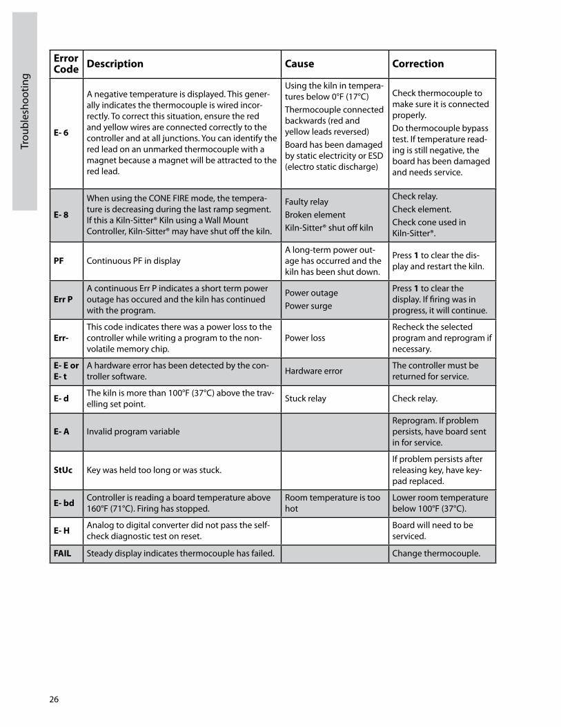
26
Trou
bles
hoot
ing
Error Code Description Cause Correction
E- 6
A negative temperature is displayed. This generally indicates the thermocouple is wired incorrectly. To correct this situation, ensure the red and yellow wires are connected correctly to the controller and at all junctions. You can identify the red lead on an unmarked thermocouple with a magnet because a magnet will be attracted to the red lead.
Using the kiln in temperatures below 0°F (17°C)Thermocouple connected backwards (red and yellow leads reversed)Board has been damaged by static electricity or ESD (electro static discharge)
Check thermocouple to make sure it is connected properly.Do thermocouple bypass test. If temperature reading is still negative, the board has been damaged and needs service.
E- 8
When using the CONE FIRE mode, the temperature is decreasing during the last ramp segment. If this a KilnSitter® Kiln using a Wall Mount Controller, KilnSitter® may have shut off the kiln.
Faulty relayBroken elementKilnSitter® shut off kiln
Check relay.Check element.Check cone used in KilnSitter®.
PF Continuous PF in displayA longterm power outage has occurred and the kiln has been shut down.
Press 1 to clear the display and restart the kiln.
Err PA continuous Err P indicates a short term power outage has occured and the kiln has continued with the program.
Power outagePower surge
Press 1 to clear the display. If firing was in progress, it will continue.
Err-This code indicates there was a power loss to the controller while writing a program to the nonvolatile memory chip.
Power lossRecheck the selected program and reprogram if necessary.
E- E or E- t
A hardware error has been detected by the controller software. Hardware error The controller must be
returned for service.
E- d The kiln is more than 100°F (37°C) above the travelling set point. Stuck relay Check relay.
E- A Invalid program variableReprogram. If problem persists, have board sent in for service.
StUc Key was held too long or was stuck.If problem persists after releasing key, have keypad replaced.
E- bd Controller is reading a board temperature above 160°F (71°C). Firing has stopped.
Room temperature is too hot
Lower room temperature below 100°F (37°C).
E- h Analog to digital converter did not pass the selfcheck diagnostic test on reset.
Board will need to be serviced.
FAIL Steady display indicates thermocouple has failed. Change thermocouple.

27
Troubleshooting
Select Fire™ FAQ'show can I correct a value that’s been incorrectly typed before pressing Enter?Clear the display by pressing all zeros, then input the correct number and press ENTER. When a cone value has been incorrectly entered the process is slightly different. After pressing 0000, press ENTER. The display will again ask for a preheat value and then a cone value. how can I change only one value for a RAMP/hOLD firing profile without re-entering the whole program?Follow the instructions for entering a new program and just press ENTER for every value that will remain the same. Make a change in the value that is incorrect, then continue.
how can I change the program after it has already started?Press the STOP key. This will stop the firing. Use either the CONE FIRE MODE or RAMP/HOLD mode to input the new firing profile for the remaining portion of the firing. Press START to resume the firing. The controller will automatically determine where to start the program (based on the current internal temperature) and proceed with the adjusted program.
The kiln shuts off too early.The kiln can be restarted if the cones on the shelf indicate an underfired load. (This should be used only if you were present when the kiln shut off.) The cones are no longer accurate if they have cooled much from the time of shut off. To restart, follow these steps:• Press CONE FIRE or RAMP/hOLD to view the firing just completed.• Press ENTER to accept any of the segments that are correct until the point where the cone number or final firing temperature is requested.• Program in a hotter cone or higher firing temperature. You could also add a few minutes of hold time at the final firing temperature.• Press START after the reprogramming is complete. The kiln will begin firing based on current temperature and will fire to completion using the newly programmed data.• Helpful hint: If the firing is just slightly under fired, program five minutes of hold time at the final firing temperature. This will allow the sections of the kiln that are somewhat cooler to catch up to the hotter sections.
The kiln displays CPLt but the kiln won’t cool off.Check the elements to see if any are still glowing inside the kiln. If a whole section of the kiln is glowing, a relay is stuck. Unplug the kiln and contact your distributor for further information.
At night I see a blue flash coming out of the control box when it clicks. Is it serious?
The flash occurs when the contacts open causing a small arc. This is a normal occurrence and should not be a concern.I programmed a RAMP/hOLD profile and when I pressed Start, the alarm sounded.Review the program to ensure that all segments of the profile have a value entered. Also, check the alarm to see if a value has been entered that is lower than the room temperature. The default setting for no alarm to sound is 9999.
The kiln is plugged in, but there is nothing on the display. First check your circuit breaker to ensure it has not tripped. If the circuit breaker is okay, check the fuse. The fuse is located on the bottom of the Select Fire™ Wall Mount Controller and on the lower left side of the kiln mounted controller. Turn the knob a quarter turn counterclockwise to remove the fuse. Check the fuse wire, and if broken, replace the fuse. If the fuse is smoky, replace it. After the fuse is replaced, if the new fuse blows, check for other possible causes. A blown fuse may be caused by a short in the circuit or a power surge.
Some segments of the display are dimmer than others.When a few segments of the LEDdisplay become dimmer than the others, the problem may be the result of age, indicating the circuit board may soon fail. Another possible cause is exposure of the controller to high heat. This situation needs attention. Do not use the kiln when this problem is present. Contact your AMACO® distributor.
The thermocouple is flaking.Flaking is normal with Type K thermocouples, especially when high fired. Use a soft bristle toothbrush to remove the flakes and vacuum them from the kiln so they do not attach to your ware. Remove the thermocouple element periodically and check it for thinning.
The end firing temperature is different now than when I first got my kiln and the results do not seem quite right. What should I do?After about 50 Cone 6 firings, or 150 Cone 04 firings, it is necessary to replace the thermocouple element. When the temperature seems to drift, it is an indication that the thermocouple is becoming thinner and wearing out. Another possibility is a cone correlation difference. As elements age it takes longer and longer for the kiln to reach temperature. Cone Fire Mode programs will automatically lower the ending temperature to compensate for the added heatwork induced by the increased time.
I pressed a number but the new cone number is not displayed.Be sure the power is on and the touchpad is active. After entering new values for any step in programming, it is necessary to press ENTER.

28
Dis
play
Mes
sage
s
Select Fire™ Display MessagesMessages displayed while accessing menu functions are described in the menu section of the manual (pages 2123). They are not listed below.
Primary Display MessagesALRM The controller is asking for an alarm temperature to be entered between 0° and 9999° that will alert the operator to take action.CONE The kiln is in CONE FIRE MODE and needs the operator to input an appropriate Cone value from 022 to 10.CPLt The controller has completed a firing profile. The firing time in hours and minutes is displayed along with the current internal temperature of the kiln. Press ENTER to return to Idle Mode.dELA This is a prompt to enter a time in hours and minutes to delay the firing before starting the program. Enter a time or all zeros for no delay.E-## A software error has occurred. Press any key to display the elapsed firing time and the temperature when the error occurred. Consult section on Error Codes for troubleshooting information.F1, F2, F3, F4, F5, F6, F7 or F8 The controller is in RAMP/HOLD mode. The user needs to input an end temperature in °F or °C for each segment of the firing profile.FAIL The thermocouple and controller are not properly connected. Fix the connection, then press ENTER to display the kiln’s current temperature. Press Start after the connection is fixed. The thermocouple could be damaged. Check the connections, if still no luck you may need a new thermocouple.hOLd Indicates a holding time in hours and minutes at the end of a CONE FIRE program.hLd1, hLd2, hLd3, hLd4, hLd5, hLd6, hLd7 or hLd8The controller is in RAMP/HOLD programming mode. The user needs to input a period of time in hours and minutes that the controller should maintain for each segment of the firing profile.-ON- Briefly displayed at the beginning of firing to indicate that the kiln has started
PROG A prompt at the beginning of a RAMP/HOLD program which allows the user to select a stored program.RA1, RA2, RA3, RA4, RA5, RA6, RA7 or RA8 The controller is in RAMP/HOLD programming mode. The user needs to input an appropriate temperature in °F/hr or °C/hr for each segment in the profile.SEGS (Looks like SE65) The controller is in RAMP/HOLD mode. The user needs to Input the number of segments in the profile being programmed.SKIP Short for Skip Step. Can be selected during a RAMP/HOLD program when one feels that adequate heatwork has been done in the current segment. Immediately advances the program to the next segment.SPd The controller is in CONE FIRE MODE. The user needs to Input the appropriate speed; slow, medium or fast for this firing.STOP Designates the intentional termination of a program while in operation.WAIT Displays at the time the kiln is initially powered up. Wait for the display to return to Idle Mode.
Miscellaneous Display MessagesFlashing temperature and IdLE The kiln is in IdLE Mode. The kiln is off and the display is showing the kiln’s current temperature. Alternating display of time and temperature The kiln is in a RAMP/HOLD firing profile and is in the soak stage. The display is indicating the kiln’s internal temperature and the remaining Hold time for that segment.Decreasing time The kiln is in a Delay start segment of a CONE FIRE or RAMP/HOLD mode. The display is showing the remaining time before the kiln starts to heat.Steady temperature The kiln is in the ramping stage of either a CONE FIRE or RAMP/HOLD fire profile. Decimal point between 10’s and 100’s Hours are to the left of the decimal and minutes are to the right.Right hand decimal point onKiln is operating in Celsius temperature scale. To change back to Fahrenheit temperature scale consult the MENU Options.

29
Manual Kiln O
peration
PreparationRemove any brick chips or other foreign matter from around the elements. Bits of bisque and glaze will eat through elements and our warranty cannot cover such accidents. We recommend that you vacuum the inside of the kiln to remove any dust that accumulated during shipment.Wipe all new shelves clean and apply a coat of AMACO® Kiln Shelf Wash to one side of each shelf. Apply a thin coating of Kiln Shelf Wash in one direction and allow to dry. Apply another thin coating in the opposite direction leaving a 1/4" margin from the outside edge of the shelf. A new coat is seldom needed—just spotpatch and sand off the surface evenly with coarse sandpaper wrapped around a wooden block. A fresh coat may be needed before a porcelain firing if glaze has dripped onto the shelf. Never kiln wash the walls or lid of your kiln!If your kiln is fitted with a Dawson® KilnSitter®/Limit Timer, it has a manual cone operated shutoff system and infinite control switches.
Test FireOnce appropriately installed, the kiln is ready for the test fire. Test firing is important to operation of the kiln as it will help to identify any installation errors that may have occurred, burn off the protective coating on the elements, and properly oxidize them to maximize their life.1. Remove firing gauge on tube assembly located in the interior of the kiln. 2. Mix a small amount of AMACO® Kiln Shelf Wash and apply a thin coat to the cone rests and the sensing rod. Do not apply wash to the end of the porcelain tube, allow wash to dry thoroughly. Do not allow wash to accumulate.3. Raise weight up against guide plate.4. Press claw down lightly until it engages trigger.5. Insert cone, while holding claw down over trigger, carefully place the cone flat on the cone supports with the inside edge of the number circle even with the outside edge of the cone support. The large part of the cone should rest against the metal step of the cone support with the center of the cone parallel with the end of the tube.
CAUTION: Since the softening and bending of the cone shuts off the kiln, correct positioning of the cone is critical to proper firing. IF CONE IS DISLODGED BY ACCIDENT OR ALLOWED TO COME INTO CONTACT WITH THE PORCELAIN TUBE, AN OVERFIRING MAY RESULT WHICH COULD CAUSE SERIOUS DAMAGE TO YOUR KILN. 6. The cone now holds the claw engaged so that the weight is supported and your hands are free. Turn the timer to approximately ½ hour longer than anticipated time for kiln to complete the firing. Press the plunger button inside the trigger weight (see arrow) until it locks. The red light will indicate that the kiln is ready to begin firing. 7. AMACO® manually operated kilns offer toggle or infinite control switches to control how fast or slow the kiln will fire. Refer to the chart on page 3233 for firing parameters.Note: In a new kiln, often the first few firings may be accompanied by odors of paint components and moisture from firebrick. During normal firings, moisture and gasses are driven off by the heat and carry a distinct odor from the kiln. In addition, in natural clays there are often im pu ri ties which may smoke or give off odors. The best remedy for these odors is good ventilation in your kiln room.
Manual Kiln OperationTOP VIEWCone
Number
Cone Number
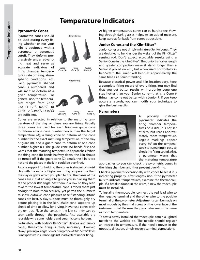
30
Tem
pera
ture
Indi
cato
rs Temperature IndicatorsPyrometric ConesPyrometric cones should be used during every firing whether or not your kiln is equipped with a pyrometer or automatic cutoff. They deform progressively under advancing heat and serve as accurate indicators of firing chamber temperatures, rate of firing, atmospheric conditions, etc. Each pyramidal shaped cone is numbered, and will melt or deform at a given temperature. For general use, the temperature ranges from Cone 022 (1112°F, 600°C) to Cone 10 (2399°F, 1315°C) are sufficient.Cones are selected in relation to the maturing temperature of the clay or glaze you are firing. Usually three cones are used for each firing—a guide cone to deform at one cone number cooler than the target temperature (A), a firing cone to deform at the cone number for the exact maturing temperature, of the clay or glaze (B), and a guard cone to deform at one cone number higher (C). The guide cone (A) bends first and warns that the maturing temperature approaches. When the firing cone (B) bends half way down, the kiln should be turned off. If the guard cone (C) bends, the kiln is too hot and the pieces in the kiln could be overfired.A cone support for holding the cones is shaped of moist clay with the same or higher maturing temperature than the clay or glaze which you plan to fire. The bases of the cones are cut at an angle to guide you in placing them at the proper 80° angle. Set them in a row so they lean toward the lowest temperature cone. Embed them just enough to hold them securely, yet permit the numbers to show. AMACO® cone plaques or self stand ing Orton® cones are best. A clay support must be thoroughly dry before placing it in the kiln. Make cone supports up ahead of time to allow for drying. Never use cones with broken tips. Place the cones in the kiln so they can be seen easily through the peep hole. Also available are reusable wire cone holders and ceramic cone holders.Fortunately, with today’s KilnSitter® devices and Junior cones, threecone firing is rarely necessary. However, always placing a single Senior firing cone at KilnSitter® level is inexpensive insurance against inadvertent underfiring.
At higher temperatures, cones can be hard to see. Viewing through dark glasses helps. As an added measure, keep ware as far back from cones as possible.
Junior Cones and the Kiln-Sitter® Junior cones are not simply miniature Senior cones. They are designed to bend under the weight of the KilnSitter® sensing rod. Don’t expect acceptable results using a Senior Cone in the KilnSitter®. The Junior’s shorter length and greater compaction make it stand longer than a Senior if placed on end, but when used horizontally in KilnSitter®, the Junior will bend at approximately the same time as a Senior standing.Because electrical power and kiln location vary, keep a complete firing record of every firing. You may find that you get better results with a Junior cone one step hotter than your Senior cone—that is, a Cone 6 firing may come out better with a Junior 7. If you keep accurate records, you can modify your technique to give the best results.
PyrometersA properly installed pyrometer indicates the firing chamber temperatures on a dial. It is not set at zero, but reads approximately room temperature. Legible markings appear every 50° on the temperature scale, making it easy to check the firing speed. Also, a pyrometer warns that the maturing temperature
approaches so you can check the pyrometric cones in the firing chamber, and thus prevent overfiring. Check a pyrometer occasionally with cones to see if it is indicating properly. After lengthy use, if the pyrometer fails to indicate temperatures, examine the thermocouple. If a break is found in the wires, a new thermocouple must be installed.To install a thermocouple, connect the red lead wire to the negative terminal and the other wire to the positive terminal of the pyrometer. Adjustments can be made on most models by the small screw on the lower face of the instrument dial. Be sure the pyrometer reads the same as room temperature.To test a newly installed thermocouple, touch a lighted match to the welded tip. The needle should register an increase in temperature. If the needle moves in the opposite direction, simply reverse terminal connections.
Guide Cone (A)
Firing Cone (B)
Guard Cone (C)
Before Firing
After Firing
Guide Cone (A)
Firing Cone (B)
Guard Cone (C)

Kiln-Sitter®The KilnSitter® is a mechanical cutoff device. A juniorsize cone mounted horizontally in the kiln, bends when the maturing temperature of the cone is attained, releasing a weighted trigger which shuts off the kiln. The KilnSitter® is designed to use only Junior Cones.The limit timer is simply a clock mechanism which you set for a time slightly longer than your anticipated firing. By keeping an accurate record of every firing, you will soon be able to estimate the length of a firing to within a half hour or less. Then, should anything go wrong with your KilnSitter®, the limit timer will turn off the kiln before overfiring can do damage.CAUTION: Automatic cutoff devices must be carefully checked and properly installed. Report any malfunction to instrument manufacturer. Since AMACO® does not manufacture these instruments, the company disclaims any liability for operational failure or resulting damage.IMPORTANT! You must adjust and test your Kiln-Sitter® on your new or repaired kiln. As good as your Kiln Sitter® is, you must calibrate and test it before you trust your ware solely to its control. Here’s what you should do before the first firing, and periodically to keep the KilnSitter® in adjustment:1. Turn switches off.2. Install the firing gauge. This metal gauge fits over the sensing rod and cone supports, positioning the rod as it should be when the KilnSitter® is properly adjusted.3. Check the clearance of the trigger and release claw. The trigger should just clear the release claw. If it strikes the claw, or has more than a few thousandths of an inch clearance, adjust the trigger height by loosening the trigger set screw. Tighten firmly when you are finished, because repeated falling can cause the trigger plate to jar out of adjustment.
4. Check the travel of the sensing rod. Remove and save your metal firing gauge. Move the sensing rod up and down. It should travel freely without touching the sides of its tube. On the outside of the kiln, the claw should move freely within the guide plate. If there is interference, loosen the guide plate screws, and center its slot so the rod and claw move freely. Tighten screws.5. Make the “2 o’clock” test. To be sure your falling weight causes the plunger to pop out, press the plunger in, raise the weight to about the “2 o’clock” position, and drop it. It should cleanly trip the plunger out.
Additional Kiln-Sitter® Notes
Your KilnSitter® is now calibrated and working properly. For trouble free operation, just remember these points.1. Never lubricate your KilnSitter®. Oils will gum up the works.2. Keep foreign objects out of the KilnSitter® tubes. Bits of ware or debris can stop the sensing rod from dropping. Check frequently.3. Keep a light coat of kiln wash on the cone sup port and sensing rod surfaces. This will be explained under the First Firing section.4. Replace bent cone supports or sensing rods. After repeated firings, these may bend. For best firing accuracy, replace them when they look distorted.5. Use only Junior cones, properly positioned as described in the Test Firing section. Tips from Senior cones will not work. After a firing, the cone should show about a 90° bend (see diagram above). Much more or less bend is a sign of in cor rect adjustment, and will cause over or underfiring.
31
Temperature Indicators
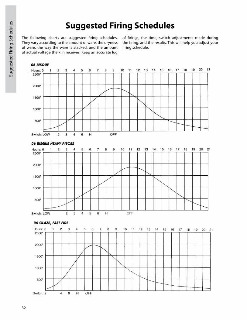
32
Sugg
este
d Fi
ring
Sche
dule
s Suggested Firing SchedulesThe following charts are suggested firing schedules. They vary according to the amount of ware, the dryness of ware, the way the ware is stacked, and the amount of actual voltage the kiln receives. Keep an accurate log
of firings, the time, switch adjustments made during the firing, and the results. This will help you adjust your firing schedule.
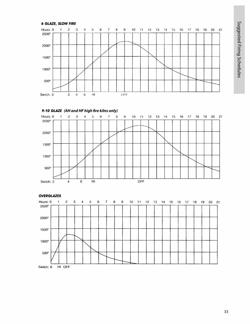
33
Suggested Firing Schedules
(AH and HF high fire kilns only)

34
Trou
bles
hoot
ing
Gui
de fo
r M
anua
lly O
pera
ted
Kiln
s Troubleshooting Guide for Manually Operated Kilns
Your AMACO® kiln is put under heavy load as it heats and cools. Like any electromechanical device, it may show signs of wear. For most home hobbyists, electrical work can be both confusing and dangerous. If this listing points to internal electrical trouble, we recommend you contact your AMACO® dealer.
Kiln-Sitter®Kiln-Sitter® consistently over or under-firing com-pared to a Senior check cone at Kiln-Sitter® level.1. Check KilnSitter® adjustments, page 31.2. Bent Junior cones from KilnSitter® deeply cracked across lower faces, indicating moisture problems. Buy new cones.
Consistently firing too hot or too cool in one section.Adjust infinite switch higher or lower on Medium and High settings to compensate.
Occasional over-firing.1. Sensing rod not accurately centered between cone rests.2. Falling weight mounting bracket bent so weight rubs against it. Refer to the Dawson KilnSitter® Timer Manual included in your packet.3. Overglaze oils or organic matter from native clays accumulated on inner face of guide plate. Remove plate, clean with lacquer thinner. Never plug top peep hole. Vent lid longer if necessary.
Senior check cone over-fired, but Junior Kiln-Sitter® cone only normally bent.1. Use magnifying glass to doublecheck numbers of both fired cones.2. Cones may erratically “freeze” if, near end of firing, the temperature rises less than 50°F (28°C) per hour or, in AMACO® kilns, when more than 1011 hours is required on High after lid is closed.
Kiln found with weight fallen but pilot light and all elements still on. Cones over-fired.1. Turn switches off. Protect hands with gloves. While kiln is still hot, perform 2 o’clock drop test, page 31, fifty times. Repeat when cooled. If plunger is released every time, you either forgot to latch the weight up when setting the cone, or the fall was impeded by the power cord or another ob struc tion.2. If any cleanly made 2 o’clock drop fails to release the plunger, contact your AMACO® dealer.
Electrical Irregular clicking noises from models equipped with Infinite Control Switches.Normal. These switches constantly cycle on and off at all settings other than High.
Elements hum at first, later do not.Normal. Kanthaltype elements are mag net ic only up to red heat. Humming then ceases.
Fuse blows or breaker trips more than one minute after switching to high.1. Fuse/breaker and wire sizes improper for the kiln. See page 5.2. Other loads on same circuit.3. Poor quality fuses or fuses loosely screwed in sockets.4. Tarnished or loose connections at a breaker or fuse socket. This can increase the temperature of either device, causing unwarranted interruptions. Contact your electrician to make the necessary repairs.Note: Your kiln will not draw more power as it ages. Aging elements can only draw less power.Fuse blows or breaker trips almost immediately after switching to high.1. Check circuit and switch box.2. Examine cord and plug for breaks.3. Check with AMACO® dealer regarding interiors of switch boxes. Power interrupted during firing, kiln is still hot.1. If still in venting stages, refire as though a fresh load, using original cones.2. If venting is completed and you know the load was never within one hour of shutoff, resume firing with the same cones, and refire as usual, except that the lid can be left closed throughout.Abrupt increase in firing time.1. Check your Senior cone, and shut off kiln manually if it is down. Check KilnSitter® thoroughly as outlined on page 31.2. If your Senior visual cone is still standing and you have confidence that it bears the correct number, check fuses or breakers. If temperature then begins to rise, complete firing as usual.3. One section not heating may mean an element has failed. When the kiln is cool, visually inspect each element for breaks. See page 35 for element replacement.4. If elements are not broken, contact your AMACO® dealer about switch box connections. 5. If problems persist, ask your power company to perform a voltage test at your wall outlet with all elements on High.

35
Troubleshooting Manual Kilns/
Element Replacem
ent
Gradually increasing firing times, often accompanied by increasingly uneven temperatures within the kiln.1. Wall receptacle defective. With main switch off, check connections, or call an electrician.2. Circuit feeding wall receptacle defective. Contact your electrician to make the repair.3. Kiln switch box connections need tightening. Contact AMACO® Technical Support for instructions specific to your kiln model. 4. Power supply problems. Power can fluctuate during peak hours—contact your local power company or a qualified electrician.5. Elements need replacement. Contact your AMACO® dealer.
Precautions and Maintenance Tips to Ensure Years of Trouble-Free Service If properly cared for and fired an AMACO® kiln will last for many years with very little maintenance but there are a few tasks that should be done regularly to ensure the kiln runs safely and effectively. • Your kiln should only be used in well ventilated areas.• Do not allow glaze or kiln wash to come in contact with heating elements.• Before each firing, brush bottom of kiln shelves and underside of the kiln lid with a soft brush.• After each bisque firing, vacuum out the element grooves, and bottom of the kiln to remove dust and stray pieces of bisque that may have broken during firing. These pieces can get caught in the elements and cause them to overheat at that point. • Periodically check your kiln shelves for cracks that run through the entire shelf. Shelves that have become this damaged are not recommended for use. • Element wire will increase in length with extended use and the coils will begin to move out of the grooves. The wire is brittle after the first fire and should not be moved or bumped when cold. Heat kiln up until red heat
(elements glow orange) for 10 minutes, disengage the power, then gently push the wire back into the grooves with a wooden tool.• The more the kiln is fired the less efficient the elements in the kiln will become. Elements in your kiln are a wearable part and will need to be replaced over time. If one element has burned out from age it is a good indication that the others will soon follow. When this happens replace all elements in the kiln. • Small cracks will appear in the soft brick of the kiln walls over time. This is to be expected and will not affect the operation of the kiln.• If it is a manual style kiln equipped with a Dawson® KilnSitter®/Limit Timer, scrape the kiln wash off the sensing rod and the cone supports and reapply every three to four firings to keep the cone from sticking to the sensing rod and over firing. • Check that all electrical connections are tight and remove any oxidation that has formed on the wires or connectors. • If it is necessary to lean over kiln while loading, be careful not to place pressure on the top inside edge of the brick. The brick is extremely fragile due to its insulating ability and can be cracked easily if one’s body weight is pressed against it.• Approximately once a month, spin all switches seven times counterclockwise and seven times clockwise. This will help to keep switch contacts clean and operating properly.• Always place a kiln shelf on the base of the kiln, supported by one inch posts to protect the base of the kiln.• During the firing process, steam and vapors vented from the kiln will cause rust and corrosion around the door and peephole. This is not a major problem with AMACO® kilns because they are fabricated of heavy gauge steel; however, occasional removal of any accumulative material will keep your kiln looking neat and attractive. Use a wire brush and sandpaper, and sand down to the bare metal. Retouch the area with heat resistant paint.
Element ReplacementWire coils in top loading kilns have a tendency to increase in length with extended use. This expansion causes the wire to slip from the grooves. Because the Kanthal wire, due to past high temperatures is brittle when cold, turn the kiln on “high” until coils glow red (about 10 minutes) then turn the kiln off. With a wooden tool, gently push the wire coils back into the grooves. It is important to turn the kiln off, and to use wood or some other nonconducting material since the coils are heated electrically. The above precautions are advised when working with high voltages and temperatures. Kanthal staples can then be used to hold element coils in place.Temperatures reached in kilns are so extreme that even Kanthal wire cannot last indefinitely; therefore, it is
important to know how to change element plates and wire in your kiln. Do not attempt to weld, splice or otherwise patch damaged wire for results will be unsatisfactory. It is also important to clean any glaze or foreign matter from element holders or element grooves, since presence of such matter can shorten element life.
Front Loading KilnsImportant: Disconnect power to the kiln before work-ing on kiln elements.In most front loading kilns, the Kanthal wires are protected by removable, high fire refractory holders. Complete plates or only wire coils may be ordered for replacements. A refractory holder need not be replaced
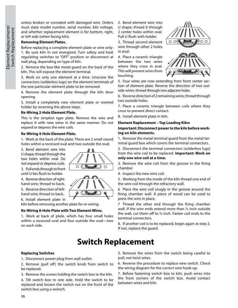
unless broken or corroded with damaged wire. Orders must state model number, serial number, kiln voltage, and whether replacement element is for bottom, right, or left side (when facing kiln).Removing Element Plates.Before replacing a complete element plate or wire only: 1. Be sure kiln in not energized. Turn safety and heat regulating switches to “OFF” position or disconnect at wall plug, depending on type of kiln.2. Remove the boxlike metal guard on the back of the kiln. This will expose the element terminal.3. Work on only one element at a time. Unscrew the connectors (solderless lugs) on the element terminals of the one particular element plate to be removed. 4. Remove the element plate through the kiln door opening. 5. Install a completely new element plate or rewired holder by reversing the above steps.Re-Wiring 2-hole Element Plate.This is the simplest type plate. Remove the wire and replace it with new wires in the same manner. Do not expand or depress the wire coils.
Re-Wiring 4-hole Element Plate.1. Work at the back of the plate. There are 2 small round holes within a recessed oval and two outside the oval.2. Bend element wire into U shape; thread through the two holes within oval. Do not expand or depress coils.3. Pull ends through to front until U lies flush to holder.4. Reverse direction of right hand wire; thread to back.5. Reverse direction of lefthand wire; thread to back.6. Install element plate in kiln before removing another plate for rewiring.
Re-Wiring 8-hole Plate with Two Element Wires.1. Work at back of plate, which has four small holes within a recessed oval and four outside the oval—two on each side.
2. Bend element wire into U shape; thread it through 2 center holes within oval. Pull U flush with holder.3. Thread second element wire through other 2 holes in oval.4. Place a ceramic triangle between the two wires where they cross in oval. This will prevent wires from touching.5. Four wires are now extending from front center section of element plate. Reverse the direction of two outside wires; thread through two adjacent holes.6. Reverse direction of 2 remaining wires; thread through two outside holes.7. Place a ceramic triangle between coils where they cross to prevent direct contact.8. Install element plate in kiln.
Element Replacement – Top Loading KilnsImportant: Disconnect power to the kiln before work-ing on kiln elements.1. Remove the metal terminal guard from the metal terminal guard box which covers the terminal connectors.2. Disconnect the terminal connectors (solderless lugs) from the wire coil to be replaced. Important: Work on only one wire coil at a time. 3. Remove the wire coil from the groove in the firing chamber.4. Inspect the new wire coil.5. Working from the inside of the kiln thread one end of the wire coil through the refractory wall.6 Place the wire coil snugly in the groove around the firing chamber wall. A piece of wood can be used to press the wire in place.7 Thread the other end through the firing chamber wall. If the wire ends extend more than ½ inch outside the wall, cut them off to ½ inch. Fasten coil ends to the terminal connectors.8. If another coil is to be replaced, begin again at step 2. If not, replace the guard.
36
Elem
ent R
epla
cem
ent/
Sw
itch
Repl
acem
ent
Replacing Switches1. Disconnect power plug from wall outlet.2. Remove (pull off ) the switch knob from switch to be replaced.3. Remove the screws holding the switch box to the kiln.4. Tilt switch box to one side. Hold the switch to be replaced and loosen the switch nut on the front of the switch box using a wrench.
5. Remove the wires from the switch being careful to pull, not twist wires.6. Reverse the procedure to replace new switch. Check the wiring diagram for the correct wire hookup.7. Before fastening switch box to kiln, push wires into the front corners of the switch box. Avoid contact between wires and kiln.
Switch Replacement

37
Heatw
ork
heatworkHeatwork is the measurement of the effects of time and temperature. In ceramics, this measurement is gauged through the use of Pyrometric Cones. They are composed of materials which are carefully measured and compressed into the shape of a tetrahedron. The cones are placed in the kiln on a shelf with your ware, and when they have received the proper amount of heatwork, they bend over indicating that it is time to turn off the kiln. Pyrometric Cones come in a variety of shapes and sizes. Each size and shape has a different temperature chart associated with it. The chart below is based on a Large SelfSupporting Cone and has become the standard for commercial clay bodies, glazes, and controller software.All clay bodies and glazes are designed to fire to a certain cone value. In a kiln with Select Fire™ the computer calculates the heatwork and shuts the kiln off at the proper heat and time combination. This is called Cone Correlation. Cone Fire Mode programs all are controlled by Cone Correlation, Ramp/Hold Programs are not.AMACO® Kilns are designed to fire a range of cone values from 022 to 10. As you can see by the chart at right, the temperature associated with each cone value gradually increases from 022 to 10. It is very important not to forget to add the leading zero when entering a cone value (if it is required) or the kiln will fire much hotter than you want it to.Remember that heatwork is the combination of time and temperature. This is most important during the last 200°F of the firing. If the kiln is firing very slow during this period, the controller will automatically adjust the temperature down to ensure the ware does not receive too much heatwork. The cone values listed in
the chart are only valid if the kiln is firing at exactly 108°F/hr. during the last 200°F of the firing. That is why it is very important to know the capabilities of your kiln when writing Ramp/Hold Programs or entering Hold times. We recommend that you still use Self Supporting Witness Cones on every firing to monitor the accuracy of your kiln. Place the appropriate cone on a shelf approximately 2 inches from the kiln wall and two inches from the tip of the thermocouple. Make sure the space between the thermocouple and cone is unobstructed.The Cone Measuring Template shown here can be used to determine the exact bend measured in degrees of angle. A perfect bend is considered to be at 90 degrees. See Cones and Firing brochure from Orton included with your kiln.For additional cone and firing information see the “Cones and Firing” brochure included with your kiln. Cone
No. ºF ºC
022 1087 586021 1112 600020 1159 626019 1252 678018 1319 715017 1360 738016 1422 772015 1456 791014 1485 807013 1539 837012 1582 861011 1607 875010 1657 90309 1688 92008 1728 94207 1789 97606 1828 998
051/2 1859 101505 1888 103104 1945 106303 1987 108602 2016 110201 2046 11191 2079 11372 2088 11423 2106 11524 2124 11625 2167 1186
51/2 2197 12036 2232 12227 2262 12398 2280 12499 2300 1260
10 2345 1285

38
Cera
mic
Def
ects
Ceramic Defects—Their Causes and how to Avoid Them
The first and most important aspect of troubleshooting defects is to be familiar with the clays, glazes and kilns used in the studio. Completely understanding how each works, the parameters of the materials, and what the “norm” for the studio is will help figure out what went wrong when pieces do not look as expected. There are many different defects that can be caused by numerous things. This section will discuss some of the most common glaze flaws and some simple inexpensive things that can be done to help reduce the occurrence of defects.
General Concepts 1. Most defects are not seen until the piece comes out of the kiln, so knowing that the kiln performed as expected is important. Even if the kiln is computer controlled, placing cone packs or selfsupporting cones will allow the user to accurately know if the kiln completed the firing as programmed. Unlike pyrometers that only measure heat, cones measure both heat and time at heat which is key to how the glaze and clay will look. Knowing that the kiln fired properly is just as valuable as knowing it didn’t when you are troubleshooting.2. Know how long your kiln cycle actually takes. If the kiln cycle normally takes 6 hours to fire and now it is taking 8½, this is a sign that perhaps elements are wearing out or possibly one or more have burned out.3. Know how the weather where you live changes by the season. These changes may be dramatic depending on locale and may affect how your clay pieces dry after forming. Drying is a function of temperature, humidity and air movement. Anything that alters these variables can cause problems. Also what works in Tampa may not work in Phoenix.4. Keep your work area clean from dust, oils, and anything that may contaminate your ceramic pieces.5. Keep your glaze containers clean and sealed to prevent bacterial growth. The same goes for the brushes used to apply the glaze.6. Watch how old the glazes are and more importantly know how they apply and dry when they are new. Older glazes (especially ones that have been poorly cared for) will tend to start to dry faster and this causes issues.7. Learn what the bisque ware pieces sound like when tapped lightly with a metal object. The sound a good piece makes is distinct and knowing that, you can determine the “clunky” dull tone of a damaged piece. Everyone can see major cracks but many cracks are small or the piece may simply have weak areas that will break when glaze fired. Knowing that a piece is not good at this point will avoid waste of decorating time, glaze and kiln space.
Drying/Forming Cracks
The causes for cracking are many and can be elusive. Listed here are some general tips for forming and drying pieces:1. Do not use excess water when wheel throwing or handbuilding pieces and attempt to keep the moisture level as even as possible throughout the piece.2. Avoid areas on a piece that are thick in some areas and thin in others. If this must be done to achieve a certain look, make sure to slow the drying process way down. This can be done by loosely covering the piece with plastic. This will take trial and error to determine how much time it will take and time will vary depending on your studio conditions. But remember that drying it too long is always better than not enough.3. Avoid sharp interior or exterior corners. Rounded corners are always better as exterior corners always dry faster than the interior of the piece. Interior corners are natural areas where stresses can be focused and start to crack.4. Avoid sharp interior and exterior edges. Same reasoning as above.5. Simple shapes like a 6" plate are much easier to dry than a 36" platter; the larger the piece the slower the drying time.6. Incising may cause stresses due to variations in thickness.7. Applied decorations need good scoring, good application of slip and slower drying to avoid cracks.8. Be careful not to unduly flex wet shapes as clay has “memory” and it will tend to go back to the warped shape even if you smooth out the warps. This may cause stress cracks.9. Throwing thick bases on pots can lead to “S” cracks on the bottom of the piece.10. In general, the more complex the shape the slower the drying process needs to be.

39
Ceramic D
efects
11. Avoid drying pieces in direct sunlight, excessively arid environments, and avoid the temptation to use fans to dry pieces. Many expert potters will use all of the techniques that were suggested to avoid, learning to push the boundaries of what can be done with ceramics comes with experience and experimentation.12. Sometimes it is important to determine if a crack occurred during the heating of a glaze firing or during the cool down phase. If a crack occurs during the heat up, it is possible to closely examine the crack to see if the glaze has run into the crack (very fluid glazes) or has at least rounded over at the edge (stiffer glazes). If it is determined that the crack has occurred during heat up of a glaze firing, one must consider slowing down the heating of the glaze firing, slowing down the cooling of the bisque firing and even looking as far back as the forming and drying of the piece.
Thermal Cracks
The causes of thermal cracks are simple; it is the rapid heating or cooling of a piece through the quartz inversion stage. The temperature at which this takes place is 1063°F. Without going into great detail, silica crystals go through a radical physical change at this temperature. If a fired piece of pottery goes through this temperature rapidly, it will not be able to adjust to the change and the piece will crack. These cracks are usually very tight and are sometimes only found by tapping on the piece to listen to the ring. In severe cases the piece will split apart into several smaller sections. It is always important when cooling the kiln to allow the temperature to fall slowly through this temperature range. When glaze and bisque firing ware, it is important to heat and cool the kiln slowly through this temperature range. Listed below are some key points to remember when firing:1. The thicker the piece, the slower the temperature rise or fall through the quartz inversion should be. Remember that when heating the kiln, the temperature of the pieces will lag behind the temperature of the kiln that the thermocouple is measuring. When cooling the kiln the opposite holds true, the piece is actually hotter than the air inside the kiln.
2. With programmable kilns it is not a problem to change the firing speed. You can select any temperature rate you desire by simply writing your own program.3. The more “open” a clay body is when it is fired, the less prone to these types of issues. Conversely, porcelains or denser clay bodies are much more prone to having thermal issues. The Raku process takes the ware through this stage very fast which is why Raku clays are normally very open, high grog content type bodies. Even with this quartz inversion, cracks are pretty common when firing Raku.
Glaze FitGlaze fit problems are simply a matter of matching the thermal expansion of the clay body and the glaze so that the glaze is slightly lower in expansion than the body. This puts the entire system into slight compression. Thermal expansion has NOTHING to do with shrinkage. All materials will expand and contract when heated and cooled. Clay bodies expand when heated and contract when cooled. We need only be concerned with glazes contracting when cooled as they are not a solid mass when heating them in the glaze firing. If the thermal fit is good the piece will be durable and stable.
Crazing
Crazing occurs when the glaze contracts more than the clay body. The glaze attempts to contract to a smaller size than the body, but the body is preventing the full contraction. Stresses build up in the system and the glaze is actually split apart to relieve the stress. These are the small thin cracks we have all seen in old china. If the mismatch is only slight, only a few large craze marks will be seen. If the mismatch is severe, many craze marks will be seen and they will be very close to each other. It is easy to see crazing on some glazes and much harder to see on others. Rubbing some India Ink onto the glaze surface will help make crazing more obvious. It should be remembered that crazing may not show up when the piece is first taken from the kiln. It may in fact take several days for crazing to appear. This is true when the mismatch is only slightly wrong. If the mismatch is severe, the crazing will happen as soon as the piece is

40
Cera
mic
Def
ects
removed from the kiln and it may in fact have started to craze while still in the kiln.Crazing never occurs because the piece was removed from the kiln too soon, it is just more apparent because the crazing is accelerated as the piece contracts. Crazing can have a delayed reaction and not show in a piece for years.
Shivering
Shivering is the exact opposite of crazing. During shivering, the glaze is actually put into compression as it is supposed to be, but it is put into too much compression. This is because the glaze wants to contract less than the clay body, but the clay body is preventing this. Stresses build up in the system until the glaze is in so much compression that it is forced to “pop” from the clay body to relieve the stress. If the shivering is only slight, this will cause small, very sharp places where part of the glaze is forced up and protrudes higher than the rest of the glaze surface. If the shivering is severe, small pieces of glaze will actually be pushed totally from the clay piece. Note: See below for more information. This should not be confused with poor adhesion of the glaze to the clay.When using commercially made products, the best way to remedy these issues is to switch clay bodies. If you have crazing, you will need a clay body with a higher thermal expansion. If you have shivering you need a body with a lower thermal expansion. As a general rule (but certainly not always true), high gloss glazes tend to have higher thermal expansions and matte glazes and underglazes tend to have lower thermal expansions. ALWAYS run test tiles of new glazes on your clay body, or if you are changing clay bodies, always test your glaze palette on it. Nothing is worse than opening the kiln to find it full of crazed and shivered pieces.
Poor Glaze AdhesionThis is a problem that most potters fail to understand fully, yet it is one of the most common problems encountered. It is important that when glazing a bisque piece or if applying an engobe or underglaze onto greenware, that the bond between the clay and the glaze be strong. Glazes are made with organic binders that help
this process by slowing the drying of the glaze to allow it to bond better to the clay and adding organic fibers to the system that helps hold the glaze to the clay. If the glaze dries too fast when applying it (especially the first layer) the bond between the glaze and the clay will be weak and it can easily be separated during the drying of the piece or in the early part of the firing schedule. The organic binders act as “food” for bacteria and if the binder is all consumed by the bacteria, the drying time will speed up and glaze popping may occur. Most commercial glazes have chemicals added to keep bacteria from growing. The bacteria eat this material and it kills them. When the entire amount of chemical is gone, the bacteria will grow. One can tell that the bacteria are growing by seeing it in the glaze or the glaze starts to have a bad smell to it. Keeping the lid on your glazes when not in use, only using clean brushes, using glaze in a timely manner, etc will keep glazes working longer.Users of glazes should mentally keep track of how their glazes dry. It will take several seconds for the glaze to lose its sheen after application. If the glaze starts to dry faster, this is a sign that problems may be ahead. AMACO® Gum Solution is a combination of binders and bactericide designed to add more organic binder into the system to replace what has been lost and bactericide to prevent future rotting. Gum solution may be added in the quantity needed to bring the glazes drying properties back to its original condition. It is impossible to recommend an amount to add to a glaze because it depends on how “bad” the drying properties of the glaze have gotten. Adding too much gum solution can cause the glaze to dry so slowly that it becomes an issue. Always add this material in small amounts until you get the glaze where you need it to be. After using it a few times you will develop a good feel for how much to add. Remember that when adding gum solution or water to a glaze, you are reducing the amount of solids you are applying to your artwork so you may want to add a little extra glaze thickness to your piece.The issue of poor glaze adhesion can happen to any type of glaze. The thicker the application of glaze or underglaze, the more likely it is for glazes to pop off. Glazes with high percentages of clay (which leads to high shrinkage of the glaze when drying) will tend to be more prone to this issue. Poor adhesion is often the case with underglaze decorations that pop off the piece as they tend to have higher amounts of clay. Many people will think that something has changed with a glaze when in fact it has simply been depleted of its organic binder. Replenishing the binder will make older glazes usable again with good results.
Glaze CrawlsGlaze crawls may be caused by many things but are usually seen as areas where the glaze has peeled back from the clay body during firing, creating a clump of glaze. Due to the surface tension of the glaze, it will not move

41
Ceramic D
efectsCeram
ic Defects
back over the bare spot. This is a very difficult defect to repair. You can attempt to grind the piled up glaze down to a level surface with the rest of the glaze, fill the hole with glaze and refire to temperature again. The defective area is usually visible even through the repair. The more important concern is to determine why the glaze crawled. There are many chemical reasons that cause glaze crawls if you formulate your own glazes. Over grinding glazes may also cause crawls. In commercially prepared glazes there are a few main causes:1. Poor adhesion of the glaze to the clay body. See the section above for possible solutions.2. Poorly cleaned bisque ware. Glazing over dusty bisque can easily cause glaze crawls. The dusty area will cause areas where glaze adhesion will be poor and cause crawls. All bisque and for that matter greenware should be totally free from loose dust.3. Do not handle greenware or bisque with any kind of grease, oil, or hand lotion on your hands. The net result of getting these materials on your pieces will again be poor glaze adhesion to the clay body. Save hand lotions for after cleanup of the area at the end of the day.4. Keeping a tidy work area and using good habits when handling greenware, bisque, your glazes and equipment will all help prevent crawls.
Over-fired WarePyrometric cones can also be important in determining if a load has been overfired. Pieces that have been overfired are usually lost. Applying a thin coat of glaze and refiring can be attempted, but this usually doesn’t fix the problem. Determining WHY the kiln overfired is important so that the problem doesn’t occur in the next firing.1. Make sure the kiln was programmed correctly and that the correct cone value was selected.2. Check the thermocouple to make sure it isn’t old and corroded. This can cause the temperature reading of the controller to be different than the actual temperature in the kiln.3. Check that the thermocouple is protruding into the kiln chamber at least 2 inches, otherwise the temperature can be inaccurate.4. Check for broken elements. A broken or weak element
near the thermocouple may cause that area to read colder than the rest of the kiln load. See Troubleshooting Guide, page 34 for additional solutions.
Under-fired Ware (Bubbles in Fired Glaze, Pinholes, Blisters)
It is ALWAYS a good idea to have a set of pyrometric cones in every kiln firing. They cost only a few pennies each and can be critical in determining if a kiln load is underfired. Underfired ware can be caused by kiln issues like weak elements or nonfunctional elements. A kiln load that is over filled may cause areas of the kiln to be underfired.Usually simply refiring the pieces to the correct temperature can correct the problem. Some potters like to apply a thin coat of glaze to the piece before refiring simply to make the glaze a little more reactive and to help it melt easier.The causes of these issues can be many but the most likely cause is offgassing of material in the clay body that cause air bubbles to either pop on the surface of the glaze or become trapped inside the glaze when it solidifies. The key is to have the gases escape from the body before the glazes melts enough to seal off the escape route of the gases. This is not always an easy thing to do because the actual cause will depend on the system the potter is using. Sometimes firing the load faster can
Pinholes
Blisters

42
solve the problem, sometimes a slower firing will work, and sometimes simply putting a thinner layer of glaze on will work. 1. Offgassing of carbonates and sulfates in stoneware bodies can be problematic if they are given off after the glaze has sealed the body over. Looking at different clay bodies may be a solution where these materials are not present. Changing glazes to ones that melt later may also solve the problem.2. Many times the bubbles will actually form in the glaze and float to the top surface of the molten glaze, the bubbles pop and the glaze surface smoothes itself out. If the glaze is applied too heavy, this extra glaze thickness may cause all the bubbles to not be liberated.3. Sometimes the issue will only happen with certain clay bodies that tend to be much more reactive. Examples of this might be red clay bodies or bodies with speckles that tend to react with glaze due to the iron or manganese and cause bubbles to form. Severe bubbles may look like large blisters. Switching to a clay body without these elements may totally eliminate the problem.4. If the glaze surface looks like most of the bubbles have popped and many have smoothed over, the solution may be a little more heat, a slower approach rate to the peak temperature or a small hold at peak.5. If the glaze surface looks like most of the bubbles are still in the glaze and only a few have popped, it might work to fire at a slightly lower temperature, approach the peak temperature at a faster rate or eliminate any hold at peak.
6. Sometimes certain glazes and clay bodies will simply not work together. It is always important to run trials on new clays or glazes. Remember that glazing a cup where almost the entire surface of the clay is covered with glaze is very different then glazing a tile which only has glaze on one surface. Gases will always attempt to find the easiest path to get out of the clay. The easiest areas for gases to escape are where the piece is not glazed.
Glaze Flowing Off the PieceAll glazes are made to work the same at peak temperature. Some glazes are formulated to flow a lot during firing to produce certain effects and some are formulated to move very little for a different aesthetic and not all glazes can be applied the same. Understanding how much your glaze will flow (move down a vertical surface) is important in determining how to glaze the piece. Running test tiles that have a vertical face is critical to understanding how the glaze will flow in the kiln. A stiff glaze may be glazed with an even applied thickness all the way down to just above the foot or all the way to the bottom if the piece is to be stilted. A very fluid glaze presents some issues that must be trialed. Glaze may need to be applied thinner near the bottom of the piece to compensate for the movement of the glaze towards the foot. In extreme cases glaze may have to not be applied near the bottom of the piece at all. If glaze flows off the piece it may cause the piece to stick to the kiln shelf which may ruin the piece and the kiln furniture. Always use liberal coats of kiln wash when working with very fluid glazes just in case.
Cera
mic
Def
ects

43
Kiln Accessories
Brent® Kiln Shelf CartNew and Improved Design!Welded bottom support rails offer added strength and stability. Powder coated steel frame with swivel, locking casters. Steel rods store (16) kiln shelves (up to 20") vertically and sep a rat ely. Includes three storage shelves. Assembled dimensions: 473/4"h x 36"l x 141/2"w.ONE YEAR WARRANTY.11779F Kiln Shelf Cart Shipping Weight 63 lbs.
Ware Cart EX Features• Top/bottom frame supports bolt into place• 1" steel pipe and welded shelf supports • Powder coated frame for greater durability and
improved scratch and corrosion resistance• heavy duty, swivel and locking casters
offer stability and easy maneuvering• Easy assembly one person can assemble alone• 9 shelf supports for greater stacking versatility• Assembled dimensions: 723/4"h x 35"w x 24"d • Optional set of (6 or 12) shelves
12" x 32" x 1/2" exterior plywood • Durable plastic cover • ONE YEAR WARRANTY
Brent® Ware Cart EX The Strongest, Most Versatile Ware Cart22633P Ware Cart EX with Plastic Cover Shipping Weight 95 lbs.22892F Set of six plywood shelves Shipping Weight 21 lbs.22634R Set of (12) plywood shelves Shipping Weight 47 lbs.22832J Ware Cart EX with set of (12) plywood shelves Shipping Weight 127 lbs.22827F Ware Cart Replacement Cover Shipping Weight 2 lbs.
Brent® Compact Ware CartMove Clay Projects Between RoomsPowder coated steel frame with welded shelf supports. Swivel/lockable casters. Optional set of (6) exterior plywood shelves. Assembled dimensions: 341/2"w x 24"d x 48"h.ONE YEAR WARRANTY.22866E Compact Ware Cart Shipping Weight 65 lbs.22928Y Compact Ware Cart, with set of (6) plywood shelves Shipping Weight 83 lbs.22892F Set of (6) plywood shelves, 12" x 32" x 1/2" Shipping Weight 21 lbs.22893H Replacement Cover Shipping Weight 1 lb.
AMACO® Kiln Accessories
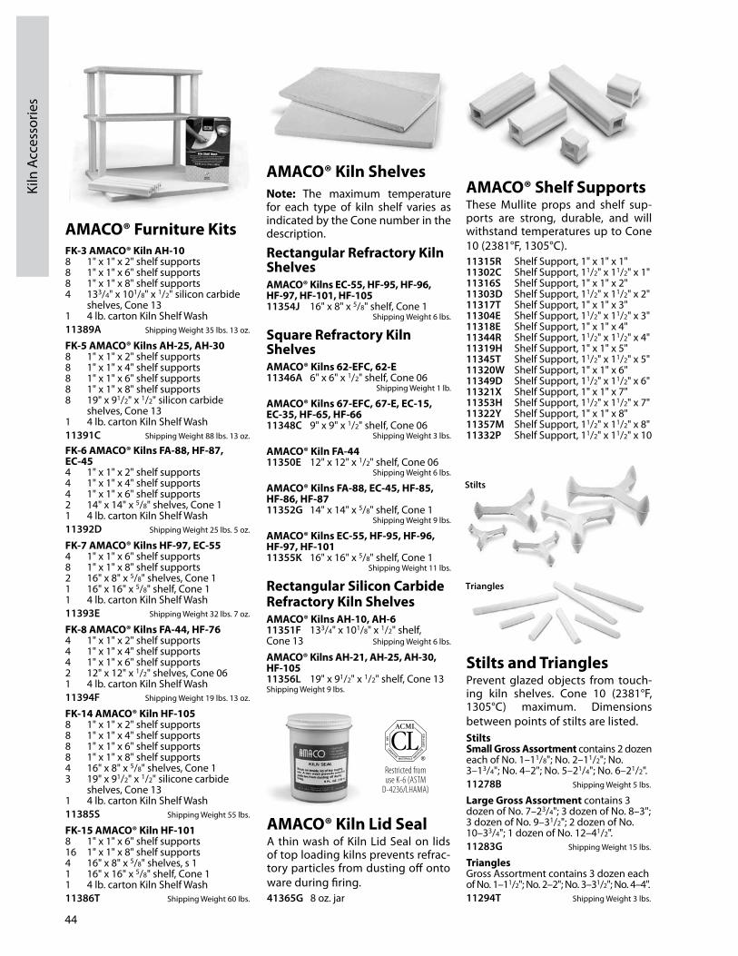
44
Kiln
Acc
esso
ries
AMACO® Kiln ShelvesNote: The maximum temperature for each type of kiln shelf varies as indicated by the Cone number in the description.
Rectangular Refractory Kiln ShelvesAMACO® Kilns EC-55, hF-95, hF-96, hF-97, hF-101, hF-10511354J 16" x 8" x 5/8" shelf, Cone 1
Shipping Weight 6 lbs.
Square Refractory Kiln ShelvesAMACO® Kilns 62-EFC, 62-E11346A 6" x 6" x 1/2" shelf, Cone 06
Shipping Weight 1 lb.
AMACO® Kilns 67-EFC, 67-E, EC-15, EC-35, hF-65, hF-6611348C 9" x 9" x 1/2" shelf, Cone 06
Shipping Weight 3 lbs.
AMACO® Kiln FA-4411350E 12" x 12" x 1/2" shelf, Cone 06
Shipping Weight 6 lbs.
AMACO® Kilns FA-88, EC-45, hF-85, hF-86, hF-8711352G 14" x 14" x 5/8" shelf, Cone 1
Shipping Weight 9 lbs.
AMACO® Kilns EC-55, hF-95, hF-96, hF-97, hF-10111355K 16" x 16" x 5/8" shelf, Cone 1
Shipping Weight 11 lbs.
Rectangular Silicon Carbide Refractory Kiln ShelvesAMACO® Kilns Ah-10, Ah-611351F 133/4" x 101/8" x 1/2" shelf, Cone 13 Shipping Weight 6 lbs.
AMACO® Kilns Ah-21, Ah-25, Ah-30, hF-10511356L 19" x 91/2" x 1/2" shelf, Cone 13Shipping Weight 9 lbs.
AMACO® Furniture KitsFK-3 AMACO® Kiln Ah-108 1" x 1" x 2" shelf supports8 1" x 1" x 6" shelf supports8 1" x 1" x 8" shelf supports4 133/4" x 101/8" x 1/2" silicon carbide
shelves, Cone 131 4 lb. carton Kiln Shelf Wash11389A Shipping Weight 35 lbs. 13 oz.
FK-5 AMACO® Kilns Ah-25, Ah-308 1" x 1" x 2" shelf supports8 1" x 1" x 4" shelf supports8 1" x 1" x 6" shelf supports8 1" x 1" x 8" shelf supports8 19" x 91/2" x 1/2" silicon carbide
shelves, Cone 131 4 lb. carton Kiln Shelf Wash11391C Shipping Weight 88 lbs. 13 oz.
FK-6 AMACO® Kilns FA-88, hF-87, EC-454 1" x 1" x 2" shelf supports4 1" x 1" x 4" shelf supports4 1" x 1" x 6" shelf supports2 14" x 14" x 5/8" shelves, Cone 11 4 lb. carton Kiln Shelf Wash11392D Shipping Weight 25 lbs. 5 oz.
FK-7 AMACO® Kilns hF-97, EC-554 1" x 1" x 6" shelf supports8 1" x 1" x 8" shelf supports2 16" x 8" x 5/8" shelves, Cone 11 16" x 16" x 5/8" shelf, Cone 11 4 lb. carton Kiln Shelf Wash11393E Shipping Weight 32 lbs. 7 oz.
FK-8 AMACO® Kilns FA-44, hF-764 1" x 1" x 2" shelf supports4 1" x 1" x 4" shelf supports4 1" x 1" x 6" shelf supports2 12" x 12" x 1/2" shelves, Cone 061 4 lb. carton Kiln Shelf Wash11394F Shipping Weight 19 lbs. 13 oz.
FK-14 AMACO® Kiln hF-1058 1" x 1" x 2" shelf supports8 1" x 1" x 4" shelf supports8 1" x 1" x 6" shelf supports8 1" x 1" x 8" shelf supports4 16" x 8" x 5/8" shelves, Cone 13 19" x 91/2" x 1/2" silicone carbide
shelves, Cone 131 4 lb. carton Kiln Shelf Wash11385S Shipping Weight 55 lbs.
FK-15 AMACO® Kiln hF-1018 1" x 1" x 6" shelf supports16 1" x 1" x 8" shelf supports4 16" x 8" x 5/8" shelves, s 11 16" x 16" x 5/8" shelf, Cone 11 4 lb. carton Kiln Shelf Wash11386T Shipping Weight 60 lbs.
AMACO® Shelf SupportsThese Mullite props and shelf supports are strong, durable, and will withstand tem per atures up to Cone 10 (2381°F, 1305°C). 11315R Shelf Support, 1" x 1" x 1"11302C Shelf Support, 11/2" x 11/2" x 1"11316S Shelf Support, 1" x 1" x 2"11303D Shelf Support, 11/2" x 11/2" x 2"11317T Shelf Support, 1" x 1" x 3"11304E Shelf Support, 11/2" x 11/2" x 3"11318E Shelf Support, 1" x 1" x 4"11344R Shelf Support, 11/2" x 11/2" x 4"11319H Shelf Support, 1" x 1" x 5"11345T Shelf Support, 11/2" x 11/2" x 5"11320W Shelf Support, 1" x 1" x 6"11349D Shelf Support, 11/2" x 11/2" x 6"11321X Shelf Support, 1" x 1" x 7"11353H Shelf Support, 11/2" x 11/2" x 7"11322Y Shelf Support, 1" x 1" x 8"11357M Shelf Support, 11/2" x 11/2" x 8"11332P Shelf Support, 11/2" x 11/2" x 10
Triangles
Stilts and TrianglesPrevent glazed objects from touching kiln shelves. Cone 10 (2381°F, 1305°C) maximum. Dimensions be tween points of stilts are listed.StiltsSmall Gross Assortment contains 2 dozen each of No. 1–11/8"; No. 2–11/2"; No. 3–13/4"; No. 4–2"; No. 5–21/4"; No. 6–21/2".11278B Shipping Weight 5 lbs.
Large Gross Assortment contains 3 dozen of No. 7–23/4"; 3 dozen of No. 8–3"; 3 dozen of No. 9–31/2"; 2 dozen of No. 10–33/4"; 1 dozen of No. 12–41/2".11283G Shipping Weight 15 lbs.
TrianglesGross Assortment contains 3 dozen each of No. 1–11/2"; No. 2–2"; No. 3–31/2"; No. 4–4".11294T Shipping Weight 3 lbs.
Restricted from use K-6 (ASTM
D-4236/LHAMA)
AMACO® Kiln Lid SealA thin wash of Kiln Lid Seal on lids of top loading kilns pre vents re fracto ry par ti cles from dust ing off onto ware dur ing firing.41365G 8 oz. jar
Stilts

45
Kiln Accessories
Restricted from use K-6 (ASTM
D-4236/LHAMA)
AMACO® Kiln CementCracks and chips in kiln re frac tory can be per ma nent ly sealed with AMACO® Kiln Ce ment. WARN ING: Do not allow direct contact with ele ments and elec tri cal wiring.52774H Dry, 5lb carton 41374R Moist, 1lb jar
Zetex GlovesMade from textured silica fabric which is inert and will not burn. Withstands temperatures up to 1000°F (538°C). Lined with cotton on palm and wool on back. Zetex gloves are 14"l x 7"w.11402P Zetex Gloves, pair
General Duty GlovesMade from cowhide with cotton lining, foam back, and wing thumb. Withstands temperatures up to 450°F (232°C). Partially sewn with Kevlar® thread.11403R Ladies, pair 11404S Men, pair
Tile/Plate SettersDeeper, wider slots hold one to eight tiles or plates for firing. Thicker base means better vertical stability. Dimensions: 8 ½"x 1 ½" x 1 ½". Maximum temperature: Cone 10 (2381°F, 1305°C).11301B Plate/Tile Setter, one pair Shipping Weight 1 lb.
AMACO® Plate SetterOne set fires one plate. Additional sets in ter lock and stack to fire up to six plates. Cone 6 (2269°F, 1243°C) maximum.11300A Set of three Shipping Weight 1 lb.
AMACO® Tile SettersHigh Fire Tile Set ters stacked on top of each other fire many tiles at once. Max i mum firing temperature is Cone 8 (2320°F, 1289°C).11306G No. 1, 8" x 61/2" x 11/8" 11307H No. 2, 91/4" x 51/2" 11/8" Shipping Weight 2 lbs.
Pointed Stilt KitsVarious shapes and sizes of stoneware stilts for firing ceramics. 11287L Small Stilt Kit Shipping Weight 2 lbs.
11288M Large Stilt Kit Shipping Weight 6 lbs.
Small Kit Large KitStilt No. Pt. to Pt. Quantity QuantityA00 .............1/4" .................................3 ....................... 0A0 ................1/2" .................................3 ....................... 6A1 ................3/4" .................................3 ....................... 6A2 ................11/4" ...............................3 ....................... 6A4 ................11/2" ...............................3 ....................... 6A6 ................21/4" ...............................3 ....................... 6A8 ................23/4" ...............................1 ....................... 3A10 .............31/2" ...............................1 ....................... 3B2x9 ...........11/4" ...............................1 ....................... 2B4x6 ...........11/2" ...............................1 ....................... 2B6x12 .........21/4" ...............................1 ....................... 2B10x15 ......31/2" ...............................0 ....................... 1C12x15 ......41/4" ...............................0 ....................... 1C14x9 .........51/4" ...............................0 ....................... 1D3B .............31/4" long ....................3 ....................... 6D4B .............4" long .........................3 ....................... 6E2S ..............13/4", 11/2" rod ............1 ....................... 1E6S ..............3", 21/2" rod .................1 ....................... 0F6H .............13/8" x 13/4"high. .......1 ....................... 2Total pieces/kit ............................ 32 .....................60
AMACO® Pointed StiltsThree metal al loy points em bed ded in stone ware base leave no mark on fired pieces. Mea sure ment given is the dis tance be tween points. Cone 04 (1971°F, 1077°C) maximum. 11264L Stilt, S1 1/4" 11265M Stilt, S2 3/4" 11266N Stilt, S3 11/4" 11267P Stilt, S4 11/2" 11268B Stilt, S5 23/4"
1 lb. Jar4 lb. CartonNON-TOXICConforms to
ASTM D-4236
40 lb. BagRestricted from use K-6 (ASTM
D-4236/LHAMA)
AMACO® Kiln Shelf WashGlaze drippings are easy to remove when the shelf is coated with Kiln Shelf Wash. 52776K 1 lb. jar 52777L 4lb carton 52778M 40lb bag

American Art Clay Co., Inc. • 6060 Guion Road, Indianapolis, Indiana 46254
AMACO® has everything you need for a successful ceramic program or studio:
AMACO® Kilns brent® Potter’s WheelsAMACO® Low & High Fire Clays brent® Ware CartsAMACO® Low & High Fire Glazes brent® Slab RollersAMACO® Underglazes & Overglazes brent® Clay ExtrudersEXCEL® Kilns Warm Glass, Kilns, and SuppliesKiln & Ceramic Accessories Textured, Hump, & Slump MoldsFurniture Kits and Shelves Brushes & Tools
For more information on AMACO®/brent® products, visit www.amaco.com, call (800) 3741600 or email:
Sales: [email protected] Support: [email protected]