AM2757 Covers for Underground Structures
31
AM 2757: Specification for Covers for Underground Structures Contents 1. INTRODUCTION ..................................................................................................................... 3 1.1. Purpose of Specification .......................................................................................................... 3 1.2. Scope of Specification.............................................................................................................. 3 1.3. Key References ........................................................................................................................ 4 1.4. Cover Types and Selection....................................................................................................... 4 1.5. Features Summary ................................................................................................................... 5 2. GENERAL REQUIREMENTS ..................................................................................................... 6 2.1. Opening and Cover System Footprint ..................................................................................... 6 2.2. Above Ground Operation of Below Ground Items .................................................................. 6 2.3. Cover Labelling ........................................................................................................................ 9 2.4. Cover Level .............................................................................................................................. 9 2.5. Winch Requirements ............................................................................................................... 9 3. FABRICATED METAL COVERS ................................................................................................. 10 3.1. Requirements ........................................................................................................................ 11 3.2. Fall Protection........................................................................................................................ 12 3.3. Cover Seals............................................................................................................................. 12 3.4. Fabricated Metal Cover Examples ......................................................................................... 13 4. MULTI-PART DUCTILE IRON COVERS ..................................................................................... 15 4.1. Requirements ........................................................................................................................ 15 4.2. Hardstand Area ...................................................................................................................... 16 4.3. Fall Protection........................................................................................................................ 16 4.4. Multi-part Ductile Iron Cover Examples ................................................................................ 17 5. TURRET TOP COVERS. ............................................................................................................ 19 5.1. Turret Top Examples .............................................................................................................. 19 5.2. Turret Top Risks and Controls ............................................................................................... 20 5.3. General Requirements........................................................................................................... 21 5.4. Floor Mounting Requirements .............................................................................................. 21 5.5. Wall Requirements ................................................................................................................ 22 5.6. Cover Requirements .............................................................................................................. 22 5.7. Cover Seals............................................................................................................................. 23 5.8. Confined Space Access Requirements ................................................................................... 23 5.9. Internal Fitout Requirements ................................................................................................ 24 5.10. Turret Top Ventilation ........................................................................................................... 24 5.11. Turret Top Approved Suppliers ............................................................................................. 24 6. ASSET INFORMATION AND REGISTRATION ........................................................................... 25 7. Fibre Reinforced Polymer Cover Additional Requirements .................................................. 25 8. APPENDIX A : COVER TYPE SELECTION MATRIX .................................................................... 26 9. APPENDIX B : COVER DESIGN ILLUSTRATIONS ...................................................................... 27
Transcript of AM2757 Covers for Underground Structures
AM 2757: Specification for
Covers for Underground Structures
Contents
1. INTRODUCTION ..................................................................................................................... 3 1.1. Purpose of Specification .......................................................................................................... 3 1.2. Scope of Specification .............................................................................................................. 3 1.3. Key References ........................................................................................................................ 4 1.4. Cover Types and Selection ....................................................................................................... 4 1.5. Features Summary ................................................................................................................... 5 2. GENERAL REQUIREMENTS ..................................................................................................... 6 2.1. Opening and Cover System Footprint ..................................................................................... 6 2.2. Above Ground Operation of Below Ground Items .................................................................. 6 2.3. Cover Labelling ........................................................................................................................ 9 2.4. Cover Level .............................................................................................................................. 9 2.5. Winch Requirements ............................................................................................................... 9 3. FABRICATED METAL COVERS ................................................................................................. 10 3.1. Requirements ........................................................................................................................ 11 3.2. Fall Protection ........................................................................................................................ 12 3.3. Cover Seals............................................................................................................................. 12 3.4. Fabricated Metal Cover Examples ......................................................................................... 13 4. MULTI-PART DUCTILE IRON COVERS ..................................................................................... 15 4.1. Requirements ........................................................................................................................ 15 4.2. Hardstand Area ...................................................................................................................... 16 4.3. Fall Protection ........................................................................................................................ 16 4.4. Multi-part Ductile Iron Cover Examples ................................................................................ 17 5. TURRET TOP COVERS. ............................................................................................................ 19 5.1. Turret Top Examples .............................................................................................................. 19 5.2. Turret Top Risks and Controls ............................................................................................... 20 5.3. General Requirements ........................................................................................................... 21 5.4. Floor Mounting Requirements .............................................................................................. 21 5.5. Wall Requirements ................................................................................................................ 22 5.6. Cover Requirements .............................................................................................................. 22 5.7. Cover Seals............................................................................................................................. 23 5.8. Confined Space Access Requirements ................................................................................... 23 5.9. Internal Fitout Requirements ................................................................................................ 24 5.10. Turret Top Ventilation ........................................................................................................... 24 5.11. Turret Top Approved Suppliers ............................................................................................. 24 6. ASSET INFORMATION AND REGISTRATION ........................................................................... 25 7. Fibre Reinforced Polymer Cover Additional Requirements .................................................. 25 8. APPENDIX A : COVER TYPE SELECTION MATRIX .................................................................... 26 9. APPENDIX B : COVER DESIGN ILLUSTRATIONS ...................................................................... 27

October 2021 Page 2 of 27
Document History
Version No. Date Author Version Description
1.0 Feb 2018 R. Jagger First Revision
2.0 R. Jagger Miller product ref update
3.0 Oct 2021 R. Jagger Section 1.5 and section 2 added

October 2021 Page 3 of 27
1. INTRODUCTION
1.1. Purpose of Specification
The purposed of this specification is to document the requirements of covers for underground
structures.
Through adoption of this documented standard, SEW is looking to optimise the following:
• Cost of construction
• Prevention of falls (to workers and members of the public)
• Ergonomics of people accessing items of equipment in underground structures
• Visual considerations
• Traffic considerations
• Structural considerations
• Odour considerations
• Life expectancy considerations (ie: UV, chemical resistance etc)
• Whole of life condition assessment and asset management
1.2. Scope of Specification
This specification is to apply to all water and sewerage underground structures which contain
mechanical and / or electrical items at or near atmospheric temperature. It is relevant to
underground structures which require regular access, whether the structures be located
under a building or outdoors.
It is to be applied to all new underground structures and any underground structures which
are being upgraded.
It is not appropriate for:
• Rarely (less often than once every 2 years) opened structures such as Sewage
Maintenance Holes.
Covers for these structures are covered by MRWA-S-313
• Openings which are not horizontal
• Very large openings (ie: openings > 20m2)
• Openings over high temperature, high / low pressure or very corrosive gases
• Openings which are not at ground level (eg: elevated covers or tank side access covers).
Where prefabricated structures come with their own proprietary cover system, approval will
be required from SEW to use the proprietary cover system unless it meets the requirements
of this specification.
This specification does not include detailed designs. Each situation is unique, and each cover
system needs to be designed specifically for each site.
Registered Engineers using this standard are responsible under the Professional Engineering
Act to determine if this is a prescriptive standard. SEW guidance is that some engineering
judgement is required to use this standard and that this standard is unlikely to fulfill the
requirements of a prescriptive standard.

October 2021 Page 4 of 27
1.3. Key References
The following key references provide further information relevant to this specification:
• MRWA Products Portal (SEW products listing)
• AM2884- Pit Standard
• AM2035- Lifting of Sewer Maintenance Covers Procedure
• AM2773- Sewage Air Valve Standard
• AM2760- Stainless Steel Specification
• AM2035- Lifting of Sewer Maintenance Structure Covers Procedure
• AS 1657- Fixed Platforms, Walkways, Stairways and Ladders
• SEW Sewage Pump Station Standards Any cover requirements stipulated in standards specific to particular asset classes (eg: Air Valve, Pit or Sewage Pump Station standards) shall take precedence over the requirements stated in this standard.
1.4. Cover Types and Selection
South East Water has four design options for underground chamber covers, which includes:
1) Fabricated metal covers
2) Multi-part ductile iron covers, and
3) Turret top covers
4) FRP covers (these are not typically used except in treatment plants)
The following process shall be adopted in selecting the optimum cover system:
A. The designer shall determine the approximate location, approximate size and a concept design for the underground chamber and cover system
B. The designer shall complete the Appendix A selection matrix and submit a copy of this and the concept design plan(s) to SEW’s design team for review
C. The final location of the underground chamber and the Appendix A selection matrix is finalised and the outcome agreed to by SEW’s design team
For Design and Construction projects, this work shall be completed during the tender or costing phase so to ensure that the correct cover systems is allowed for. The main issues to consider when deciding on the optimum cover system include: • whether the covers are required to be trafficable
• life cycle cost and required asset life
• maintenance and community risks associated with the structure
• the risk of fugitive emissions from the structure
• the location of the structure relative to features in the neighbouring environment

October 2021 Page 5 of 27
1.5. Features Summary
Cover system requirements are summarised in Table 1 below:
Feature Fabricated Metal Covers
Multi-part Ductile Iron Covers
Turret Top Covers
Trafficable areas ✓
Non-trafficable areas ✓ ✓
Permanent guard rails ✓
Temporary guard rails ✓
Ground level standing area within guard rail enclosed area
✓ ✓
Fall protection davit arm insertion sleeve(s)
✓ ✓ ✓
Under cover fall arrest grating with removable sections to access items
✓
Post & winch capability for covers > 20 kg
✓ ✓
Lifting chains for covers <=20 kg ✓
Lifting handles for covers ✓ ✓
Above ground operation of chamber enclosed critical isolation valves
✓ ✓ ✓
Covers labelled with content below ✓ ✓ ✓
Restrained while open ✓
Hardstand area around the opening ✓ ✓ ✓
Lockable with standard SEW lock ✓ ✓
Cover seals ✓ ✓
Low odour risk ✓

October 2021 Page 6 of 27
2. GENERAL REQUIREMENTS
2.1. Opening and Cover System Footprint
To facilitate SEW’s consideration of the optimum cover system, the designer shall provide
SEW with an initial plan of the equipment and chamber / pit outline with preferred
dimensions of the opening’s footprint that will need to be covered.
The opening and cover system footprint shall:
• Enable high maintenance equipment in the underground structure to be replaced by raising the equipment vertically from its installed position, with a minimum clearance between the equipment’s outline and the opening’s perimeter of 100mm.
• Enable the required worker access into the structure. As per AS 1657, a 750 x 750 working space is required from the front edge of any ladder at the top and bottom of the ladder. Should worker access to the chamber be via a craned workbox, the opening shall be sufficiently large to facilitate a workbox of appropriate size being lowered into position. A minimum clearance between the craned workbox outline and the opening’s perimeter of 200mm shall be provided in such cases.
• Provide the above clearances while other fixtures and fittings (eg: pump chains, junction boxes, instruments) are located in their normal operating position.
2.2. Above Ground Operation of Below Ground Items
Where practical, below ground covered items which require frequent or critical manual operation shall be operable from ground level when the cover(s) are either open or closed. Underground chamber located items that require this include but are not limited to:
• Air Valve isolation valves
• Main in line isolation valves
• SPS non-return valve pit isolation valves
• Education point isolation valves
• Bypass valves (eg: around PRVs, flow meters, large divide valves etc)
• Penstocks and knifegate valves This typically means that such valve spindles for these items shall:
• Be extended to just below cover level (< 100 from bottom of cover level)
• Be designed so that the valve has adequate lock out – tag out capability, eg: locking tabs
• Extend to this level using permanent spindle extension(s) which are designed and fabricated in accordance with standard drawings SEWL-STD-003 and 004.
• Where the top of the pit includes both a fixed ceiling and cover(s), the spindle shall typically be brought through the ceiling to within a winding box which is cast into the ceiling/cover slab as per standard drawing SEWL-STD-004 and 006. This applies whether a turret top, fabricated metal or ductile iron cover system is used in conjunction with a ceiling.
• Where vertical spindle extensions are located within an opening, they shall be mounted such that they are 100 to 200 from the edge of an opening. This may require one or more 90 degree spindle gearboxes to enable. In this way, the valve shall be operable from ground level while cover(s) are open, with the operator able to stand outside the fall protection system, place a valve key or hand

October 2021 Page 7 of 27
wheel on the spindle and rotate the spindle without the valve key or handle interfering or clashing with any above ground assets (fall protection assets in particular).
• For fabricated metal and multi-part ductile iron covers where vertical spindle extensions are located within an opening, they shall be operable from ground level while the cover system is closed.
• Fabricated metal covers without ceilings will require a small (~100 x ~100) opening located centrally above the extension spindle with a separate hinged cover for this opening. This small hinged cover shall be constructed of metal plate and utilise a 3mm SS316 piano hinge with a recessed SS round finger edge pull insert adjacent to the edge opposite the hinge.
Figure 1: Spindle Extension to Fabricated Metal Cover Opening
• Turret Top covers without ceilings will require a handwheel with attached short spindle extension which could be placed on the permanent spindle extension (which will extend to just under bottom of cover level) for valve operation. This handwheel and short spindle extension shall be restrained to the spindle so it is accessible while standing at ground level and not able to fall. Stainless Steel crimps shall be in used in lieu of copper crimps on any braided stainless steel restraint cable. While not in operation, any handwheel with attached short spindle extension should be stored in such a way that it is secure, would not fall and would not interfere with the removal of frequently maintained items (such as submersible pumps). Typically, the best storage location is at the corner of the turret top where there is greater clearance from items during their removal. Alternatively locate the handwheel with attached short spindle extension in a nearby cabinet.

October 2021 Page 8 of 27
Figure 2: Spindle Extension to Turret Top Opening
• Multi-part Ductile Iron covers without ceilings will require a small (ie: ~50 diameter) circular opening to be cored through the cover which is to be fitted with a removable plug. Contact the cover supplier for advice on the proper location and size of holes to be cored. Typically, holes shall be cored in the “pocket” of the cover which is the space clear of structural strengthening ribs. Spacing between ribs varies, but is typically 50 (for 900 long covers) or 80 (for 450 and 600 long covers). Care should be taken to ensure support beams and cover ribs are not directly over the spindle, but that a cover’s “pocket” is directly above the spindle. Fall protection systems shall not impede or interfere with spindle operation when covers are either open or closed.
Figure 3: Spindle Extension to Ductile Iron Covered Opening

October 2021 Page 9 of 27
2.3. Cover Labelling
All multi-part covers shall be labelled with the chamber / pit contents below that cover.
Equipment naming shall be consistent with the equipment naming convention described in
AM2775- WaterShed Data Collection Details and Appendix A of AM2714- Electrical Standards.
Engraved labels with text > 10mm high are preferred to printed lables.
2.4. Cover Level
All covers shall be set at a level that is 150 above the 1 in 5 year flood level. The covered area
shall clearly drain away from the covers. Where practical, this shall be undertaken by grading
the finished surface down from the covers on all sides at a grade steeper than 1 in 60. No
ponding of water over the covered area is acceptable.
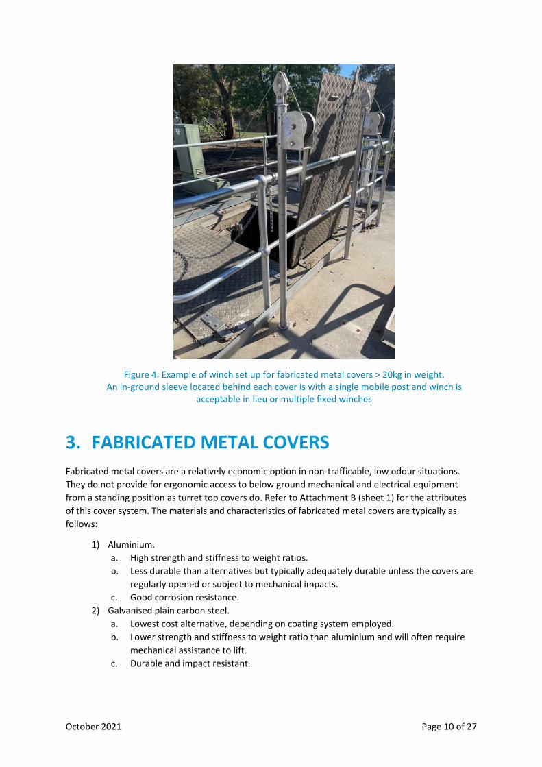
2.5. Winch Requirements
All fabricated metal and turret top covers > 20kg in weight shall be provided with the
capability to be winched open and closed with a winch system that has the following features:
• Is constructed of stainless steel (at least the structural and mechanical elements)
• Consists of a pole mounted winch where the pole can be inserted into below ground
sleeves.
• Sleeves may need to be inserted into core drilled holes within the a cover’s existing
concrete slab and shall be below ground. Sufficient clear cover of the sleeve hole and
opening shall be provided.
• Sleeves shall consist of hot dipped galvanised or stainless steel sleeve, 5mm wall
thickness, cast or epoxied in place, with a plastic soil exclusion cap.
• Provides a single sleeve directly behind every cover that is > 20kg on weight.
• Sleeve must be of the appropriate internal diameter for the pole mounted winch and
crane provided.
• Mobile pole mounted winch and crane shall be kept on site in a cabinet where practical.
Where another cabinet exists in site, it is preferred that this be extended to accommodate
the winch crane.
October 2021 Page 10 of 27
Figure 4: Example of winch set up for fabricated metal covers > 20kg in weight. An in-ground sleeve located behind each cover is with a single mobile post and winch is
acceptable in lieu or multiple fixed winches
3. FABRICATED METAL COVERS
Fabricated metal covers are a relatively economic option in non-trafficable, low odour situations.
They do not provide for ergonomic access to below ground mechanical and electrical equipment
from a standing position as turret top covers do. Refer to Attachment B (sheet 1) for the attributes
of this cover system. The materials and characteristics of fabricated metal covers are typically as
follows:
1) Aluminium.
a. High strength and stiffness to weight ratios.
b. Less durable than alternatives but typically adequately durable unless the covers are
regularly opened or subject to mechanical impacts.
c. Good corrosion resistance.
2) Galvanised plain carbon steel.
a. Lowest cost alternative, depending on coating system employed.
b. Lower strength and stiffness to weight ratio than aluminium and will often require
mechanical assistance to lift.
c. Durable and impact resistant.

October 2021 Page 11 of 27
d. Poor corrosion resistance and reliant on high quality coating systems. Refer to WSA
201 for selection and application of protective coatings. Required to be galvanised
and epoxy coated.
e. Not to be used in situations where covers are exposed to sewage, corrosive gases or
sea spray.
3) Stainless Steel.
a. Similar mechanical properties to plain steel covers.
b. Highest corrosion resistance (depending on grade- refer AM2760).
c. Highest cost alternative.
Aluminium covers are typically preferred unless covers are small (and weight not an issue even for
other cover materials) or mechanical lifting assistance is required, even if aluminium covers were
selected.
3.1. Requirements
Fabricated metal covers shall be:
• Used only where there is a low risk of odour impacts. Fabricated metal covers may warp during fabrication, warp during their operational life and the rubber seals tend to compress over time, creating gaps in the cover joins from which odours can escape. This makes fabricated metal covers inappropriate for structures which contain odour that may negatively affect customers.
• Non-trafficable. They shall only be used inside a building or within an area protected from traffic.
• Usually the best option within buildings, unless odour gases leaking from the underground chamber into the building may be a risk.
• Located at, or slightly above ground level
• Used in conjunction with permanent guardrails.
• Wherever possible be hinged and lightweight such that one person can lift the cover (ie: < 20 kg each cover). Where cover weight exceeds 20 kg, winch capability shall be provided for each cover to enable the safe operation of the cover (refer section 2.5).
• Designed to ensure that they will in no way clash or obstruct nearby structures or items when the covers are opened and closed. This can often be a problem if fabricated metal covers are located adjacent to a turret top cover system.
• Locked (as per the SEW’s Facility Security requirements) with a standard SEW shank lock when located outside to prevent unauthorised access.
• Designed to ensure that there is no more than a 5mm deflection when a 1 kN (100 kg) is placed anywhere on any cover.
• All handles and locks should be recessed below cover level so they do not sit proud and create a potential tripping hazard.
• Covers shall not be openable beyond nominal 120 degrees to avoid the cover becoming a tripping hazard when open or taking up more space than necessary. Normally, permanent guardrails limit the degree to which covers can open.
• Restrained in the open position using a quick catch / release mechanism (eg: SS wire and carabineer or galvanised steel welded link chain) which enables covers to be easily attached to the permanent guardrails. This mechanism shall be sufficiently sturdy that strong winds and large horizontal forces on the cover will not cause the restraint to fail.
• Provided with lifting chains, constructed of minimum 2mm thick galvanised or stainless steel welded link chain, fixed to the outer edge of the cover and tied off on the permanent guardrail opposite.

October 2021 Page 12 of 27
• Lifting chains and cover restraints shall consider ergonomics.
• Designed to enable items within chambers/pits to be operated as described in section 2.2.
• Inclusive of fall-from-heights protection as described below.
3.2. Fall Protection
Fall protection associated with fabricated metal covers shall:
• Be provided when the underground structure is deep (ie: > 1.5m).
• Comply with the requirements indicated in Figure 5.
• Include the provision of permanent guardrails which shall: 1. comply with AS 1657 (fixed platforms, walkways, stairways and ladders) where
practical. 2. constructed of galvanised steel to AS/NZS 4680 and AS 2309 or grade 316
stainless steel. 3. Include >100mm high kick plates at ground level. 4. Have a latched hinged gate to provide access through the guardrail to any
internal ladder within the structure. This gate shall swing outwards and be spring loaded to automatically return to the closed position after use. Gates shall be between 600 and 750mm wide.
5. Have posts securely fastened to the cover slab, each with a minimum 4 fasteners which comply as a minimum to MRWA sewerage standard figures 314-F or 314-G.
• Provide sleeve(s) for davit arm insertion which shall be: 1. Miller Flush Mount Floor Sleeve, model DH-20SS (for insertion into the top of new
concrete slabs). 2. Miller Floor Mount Sleeve, model DH-7SS (for attachment to the top surface of
existing concrete slabs). Where these are used, they shall be carefully positioned to avoid becoming a tripping hazard.
3. >100mm clearance from the side of a ladder (out of the way of the ladder) 4. As close as possible to the opening but also with at least 75mm edge distance
between the sleeve and the opening to maintain adequate structural concrete around the sleeve.
• Temporary guardrail arrangements and under cover grating (refer section on ductile iron covers) may be acceptable where permanent guardrails will adversely impact on the functionality of the site. The use of an under cover grating fall protection system used in conjunction with fabricated metal covers requires South East Water approval.
• Provide a means to attach / restrain open fabricated metal covers to the guardrail system.
3.3. Cover Seals
Cover seals shall be provided for covers over chambers which may contain sewage.
Cover seals shall:
• Be attached to covers (not the main structure).
• Provide a gas tight seal between covers &/or opening edges. The gas seal shall be sufficient that when a piece of tissue paper is held near the seal during any normal operation of the site on a windless day, it will not noticeably flutter.
• Be non-perishable and proven to be resistant to a high hydrogen sulphide environment ie: constructed from EPDM or Neoprene.

October 2021 Page 13 of 27
• Be resilient and continue to provide an effective compressed seal under continual closure for at least 10 years.
• Have seals that neatly match the entire surface to which they mate.
3.4. Fabricated Metal Cover Examples
Figure 5: Set up of Fabricated Metal Covers with Fall Protection (refer Appendix B for details)
Figure 6: Example of aluminium covers with permanent guard rails inside a building. (Note: a ground level standing area in front of the ladder inside the guardrail area has not been provided in this example but shall be provided if practical. Refer Figure 1)

October 2021 Page 14 of 27
Figure 7: Example of external aluminium covers with permanent guard rails (Note: a ground level standing area in front of the ladder inside the guardrail area has not been provided in this example but shall be provided if practical. Swing gates to enable worker entry inside the guard rail area is also required. Refer Figure 1)
Figure 8: Example of unacceptable external aluminium covers with fold up guards. (Note: This arrangement would not be acceptable because fabricated metal covers require permanent guardrails)
October 2021 Page 15 of 27
4. MULTI-PART DUCTILE IRON COVERS
For single ductile iron covers, refer to MRWA-S-313 and 313B.
South East Water preferences are as follows:
1) Non-trafficable turret top and fabricated metal cover systems be adopted. The designer shall
document and submit a compelling justification as to why any underground chamber or pit
cannot practically be located in a non-trafficable location. This justification shall include a cost
and risk assessment of the alternative options.
2) Single row multi-part ductile iron cover systems shall be utilised rather than multiple row
system which require undercover support beams. Multiple row ductile iron cover systems are
not typically permitted and require South East Water approval.
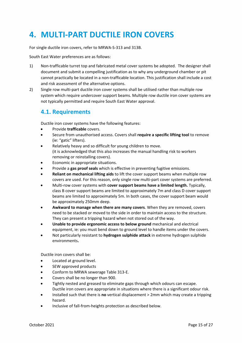
4.1. Requirements
Ductile iron cover systems have the following features:
• Provide trafficable covers.
• Secure from unauthorised access. Covers shall require a specific lifting tool to remove (ie: “gatic” lifters).
• Relatively heavy and so difficult for young children to move. (it is acknowledged that this also increases the manual handling risk to workers removing or reinstalling covers).
• Economic in appropriate situations.
• Provide a gas proof seals which is effective in preventing fugitive emissions.
• Reliant on mechanical lifting aids to lift the cover support beams when multiple row covers are used. For this reason, only single row multi-part cover systems are preferred.
• Multi-row cover systems with cover support beams have a limited length. Typically, class B cover support beams are limited to approximately 7m and class D cover support beams are limited to approximately 5m. In both cases, the cover support beam would be approximately 250mm deep.
• Awkward to manage when there are many covers. When they are removed, covers need to be stacked or moved to the side in order to maintain access to the structure. They can present a tripping hazard when not stored out of the way.
• Unable to provide ergonomic access to below ground mechanical and electrical equipment, ie: you must bend down to ground level to handle items under the covers.
• Not particularly resistant to hydrogen sulphide attack in extreme hydrogen sulphide environments.
Ductile iron covers shall be:
• Located at ground level.
• SEW approved products
• Conform to MRWA sewerage Table 313-E.
• Covers shall be no longer than 900.
• Tightly nested and greased to eliminate gaps through which odours can escape. Ductile iron covers are appropriate in situations where there is a significant odour risk.
• Installed such that there is no vertical displacement > 2mm which may create a tripping hazard.
• Inclusive of fall-from-heights protection as described below.
October 2021 Page 16 of 27
• Designed to enable items within chambers/pits to be operated as described in section 2.2
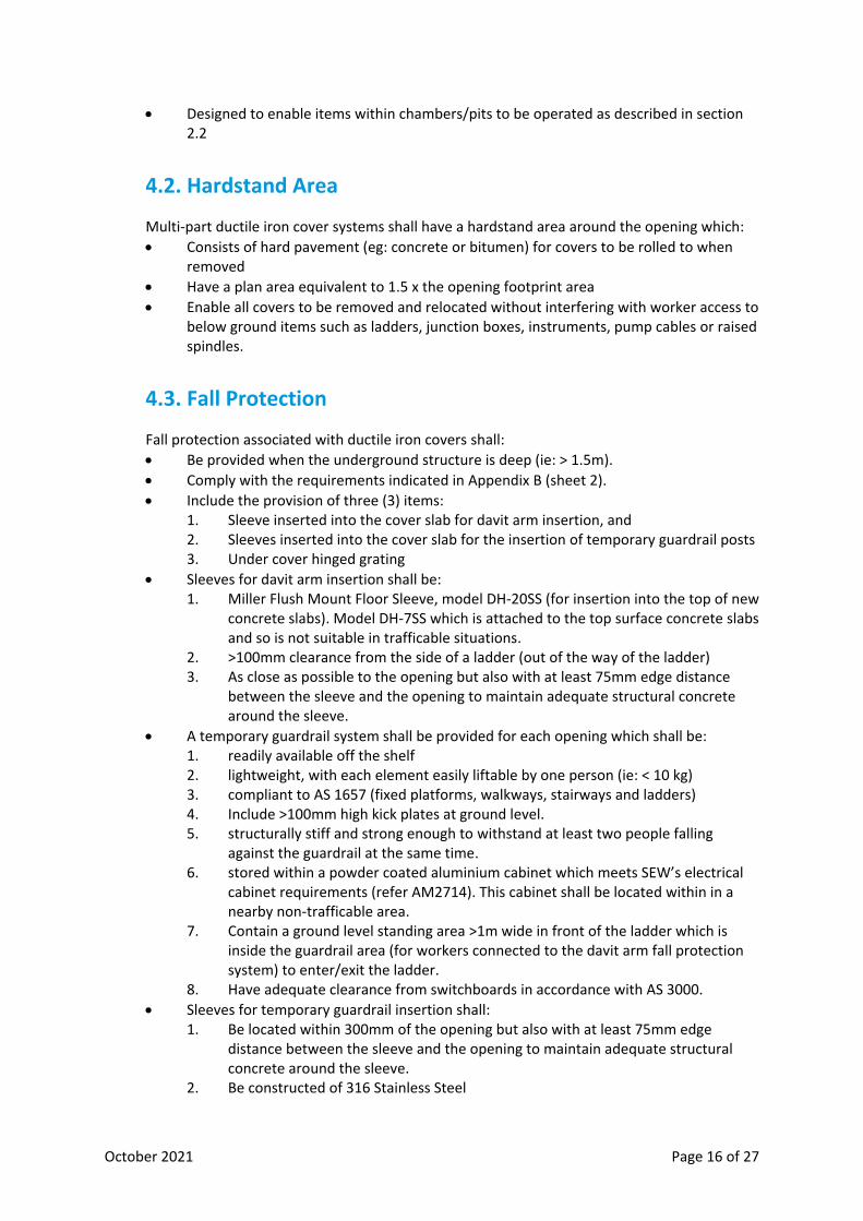
4.2. Hardstand Area
Multi-part ductile iron cover systems shall have a hardstand area around the opening which:
• Consists of hard pavement (eg: concrete or bitumen) for covers to be rolled to when removed
• Have a plan area equivalent to 1.5 x the opening footprint area
• Enable all covers to be removed and relocated without interfering with worker access to below ground items such as ladders, junction boxes, instruments, pump cables or raised spindles.
4.3. Fall Protection
Fall protection associated with ductile iron covers shall:
• Be provided when the underground structure is deep (ie: > 1.5m).
• Comply with the requirements indicated in Appendix B (sheet 2).
• Include the provision of three (3) items: 1. Sleeve inserted into the cover slab for davit arm insertion, and 2. Sleeves inserted into the cover slab for the insertion of temporary guardrail posts 3. Under cover hinged grating
• Sleeves for davit arm insertion shall be: 1. Miller Flush Mount Floor Sleeve, model DH-20SS (for insertion into the top of new
concrete slabs). Model DH-7SS which is attached to the top surface concrete slabs and so is not suitable in trafficable situations.
2. >100mm clearance from the side of a ladder (out of the way of the ladder) 3. As close as possible to the opening but also with at least 75mm edge distance
between the sleeve and the opening to maintain adequate structural concrete around the sleeve.
• A temporary guardrail system shall be provided for each opening which shall be: 1. readily available off the shelf 2. lightweight, with each element easily liftable by one person (ie: < 10 kg) 3. compliant to AS 1657 (fixed platforms, walkways, stairways and ladders) 4. Include >100mm high kick plates at ground level. 5. structurally stiff and strong enough to withstand at least two people falling
against the guardrail at the same time. 6. stored within a powder coated aluminium cabinet which meets SEW’s electrical
cabinet requirements (refer AM2714). This cabinet shall be located within in a nearby non-trafficable area.
7. Contain a ground level standing area >1m wide in front of the ladder which is inside the guardrail area (for workers connected to the davit arm fall protection system) to enter/exit the ladder.
8. Have adequate clearance from switchboards in accordance with AS 3000.
• Sleeves for temporary guardrail insertion shall: 1. Be located within 300mm of the opening but also with at least 75mm edge
distance between the sleeve and the opening to maintain adequate structural concrete around the sleeve.
2. Be constructed of 316 Stainless Steel

October 2021 Page 17 of 27
3. Be fitted with removable caps, set just below the top surface level 4. Have an internal diameter compatible with the selected temporary guardrail
posts. 5. Have a depth > 200mm while still enabling the erected guardrail structure to
achieve minimum height.
• Undercover hinged grating shall: 1. Be hinged along the outer edge so that the grating can hinge upwards and out of
the way of human entering the structure. 2. Normally rest in the horizontal closed position against a load bearing positive
stop. 3. Rest in the open position against the cover slab or temporary guardrail, with a
316 stainless steel quick catch / release mechanism (eg: SS wire and carabiner) which enables the grating to be easily restrained in the open position.
4. Consist of stainless steel (refer SEW stainless steel specification) mesh with bars (flat or round) at 100mm separation in both dimensions.
5. Be designed to ensure that there is no more than a 5mm deflection when a 1 kN (100 kg) is placed anywhere on the grating.
6. Not contain any openings / gaps wider than 200mm. 7. Contain separate non-entry smaller openings above items (eg: junction boxes,
raised spindles) that require regular access. A small hinged grate shall be provided to cover this opening, which shall be large enough to easily work on the below item but not large enough for humans to fall through (eg: < 300 diameter).
4.4. Multi-part Ductile Iron Cover Examples
Figure 9: Ductile Iron Cover and Fall Protection Arrangements.
Exploded isometric section view showing guardrail system suspended above the installed position. Refer to Appendix B for details

October 2021 Page 18 of 27
Figure 10: Example of Multipart trafficable concrete infill ductile iron covers (Guard rail system not yet installed)

October 2021 Page 19 of 27
5. TURRET TOP COVERS.
Turret top covers are the most common type of cover over pump wells. They provide safe, rapid and easy operations and maintenance access to equipment. They are typically used for larger pumps, or situations where odour risks are significant and the pumps are located in a non-trafficable area. Refer to Appendix B (sheet 3) for details. Turret top covers are:
• A bespoke metal fabrication that mounts the covers at a handrail height above an underground structure cover slab.
• Able to provide solid protection against accidental fall-from-heights and confined space entry risks, even when the covers are fully open.
• Able to prevent fugitive emissions when the rubber seals are maintained and under compression.
• Able to provide ergonomic access to mechanical plant and electrical/instrumentation equipment, which shall be mounted at waist height where practical.
• Expensive relative to fabricated metal or ductile iron covers.
• Possibly obstructive to driver / rider / pedestrian visibility when located near roads.
• Possibly detrimental to the visual aesthetics of highly public neighbourhoods.
5.1. Turret Top Examples
Figure 11: Example of turret top close up (note: missing rubber door stoppers)

October 2021 Page 20 of 27
Figure 12: Example of turret top opened-up (next to aluminium covers opened-up) (Note that fabricated metal covers shown are not compliant)
Figure 13: Turret Top Arrangements (isometric view) (refer to Appendix B for details)
5.2. Turret Top Risks and Controls
While turret tops effectively minimise work time, control fall-from-heights, control
unintentional Confined Space Entry and various ergonomic and manual handling risks, other
risks that need consideration include:
1) Traffic Risks.
When turret tops are located near roadways, they can hinder the visibility of drivers,
riders and pedestrians. Such locations can also increase the need to protect the turret
top from collisions with impact rated bollards or barriers, reducing access to the
structure. These risks increase as the proximity and volume of traffic increases. The site
layout design can reduce these risks, though in some cases trafficable covers may be
preferable. Fences, gates and bollards can be used to reduce the risk of collision.

October 2021 Page 21 of 27
2) Local aesthetic and community acceptance issues.
Turret tops may create aesthetic issues when located in or near high profile public land.
Stakeholder consultation may be required to determine if there are any special
requirements. In sensitive areas, the site layout design may be able to address such
issues or the turret top may need to be painted in a particular way. Failing that, ground
level covers may need to be utilized.
3) Overhead cables.
As a crane is required to lift heavy items, such as pumps, over the turret top wall,
clearance to overhead cables can be problematic. The designer needs to measure
heights to overhead cables, consider electrical no go zones and crane boom heights and
then calculate whether items can be safely removed with a turret top in place. If items
cannot be safely lifted, ground level covers may be a viable alternative.
4) Reduction in work space during opening of the covers.
Turret top covers need to be able to rotate through almost 270 degrees whilst still
providing adequate space for workers to stand nearby as this occurs.
5.3. General Requirements
Turret tops shall be designed and manufactured:
• To prevent unintentional or unauthorised access to underground structures.
• To enable easy access to all mechanical and electrical items in the underground
structure for maintenance activities.
• In a factory environment as much as practical.
• Such that all visible sheet metal / plate surfaces are powder coated 300 micron thick to
Colourbond Rivergum gloss G62.
• Such that all coatings are applied in a factory environment where practical. Coating
damage which occurs during transport or installation shall be checked as part of the ITP
(Inspection and Test Plan) and reported to SEW once detected. Only minor coating
damage (ie: < 5cm2) may be repaired on site.
• With folded seams / joins as much as practical. Remaining seams / joins shall be welded
where practical unless the item needs to be removable, in which case fasteners may be
used.
• Such that externally accessible fasteners are tamper proof.
• Such that stainless steel components comply with AM 2760 Stainless Steel Specification.
5.4. Floor Mounting Requirements
Turret top floor mountings shall:
• Closely matches the opening of the top slab (0 to +20mm larger than the opening in
either dimension).
• Mount entirely on the top surface slab of the underground structure.
• Have a contact surface between the turret top and top slab which is 40 to 75mm wide.

October 2021 Page 22 of 27
• Be fastened to the top slab with removable min M10 stainless steel fasteners spaced at
less than or equal to 600mm centres. Fasteners shall be removable from directly above
(i.e: not located within a recess.
• Include a min 5mm thick and >40mm wide butyl mastic seal applied around the entire
interface between the turret top and top slab (with no gaps to provide a gas seal).
• Be constructed from min 3mm thick stainless steel sheet.
• Be welded to or folded from the turret top wall.
5.5. Wall Requirements
Turret top walls shall:
• Be between 1000mm and 1100mm high, noting that the height of the wall needs to be
sufficient to enable the covers to hang nearly vertical in the open position.
• Be constructed from min 3mm thick stainless steel sheet.
• Be stiff enough to ensure that a horizontal 1 kN point load applied anywhere on the wall
causes less than a 5mm deflection.
• Be stiff enough to ensure that where ladders are fixed to walls, a 100kg person climbing
anywhere on any ladder will cause less than a 5mm deflection anywhere on the wall.
• Support all guiderails and be stiff enough to ensure that the positioning of both pumps
anywhere along the guiderails will cause less than a 5mm deflection anywhere on the
wall.
5.6. Cover Requirements
Turret top covers shall:
• Be able to be easily opened by hand (without a mechanical lifting aid) while standing on
the ground slab.
• Have sufficient open space around the covers such that the covers can be fully opened
without interfering with workers standing adjacent to the covers. Workers should be
provided with a minimum of 1000mm paved standing room between an opening cover
and any nearby obstruction.
• Be constructed from minimum 3mm thick marine grade (grade 5052, 5083 or 6064-T4) aluminium sheet.
• Wherever possible, covers shall be hinged and lightweight such that one person can lift
the cover (ie: < 20 kg each cover). Where cover weight exceeds 20 kg, a winch shall be
provided for each cover to enable the safe operation of the cover (refer section 2.5).
• Where cover openings are large and cover weights are not suitable for winch removal,
roll on – roll off covers may be a more suitable alternative. Lifting bars may also fitted to
swing covers to reduce the effort required to move them.
• Be stiff enough to ensure that a vertical 1 kN point (100 kg) load applied anywhere on a
cover causes less than a 5mm deflection (relative to the perimeter of the cover, ie:
excluding seal compression. Test would involve placing a 100kg weight anywhere on the
cover, holding a straight edge across the cover and measuring the max deflection).
• When fully open, rest against rubber stops fitted to the turret top walls. To avoid metal
or coating damage, open covers shall not contact the coated sheet metal wall surface.

October 2021 Page 23 of 27
• When open, swing covers shall hang in a near vertical alignment (i.e. nearly parallel to
the turret walls, approximately 270 degree swing) to enable workers to reach over the
covers to access items inside the turret top.
• Each be fitted with at least one lifting handle near each cover’s edge which is easily
accessible while standing on the underground structure’s cover slab.
• Have a closing mechanism which has a lever action that ensures adequate compression
of the seal. Closing mechanisms fitted to covers should be lightweight to reduce the
overall weight of covers.
• Have a closing mechanism which can be secured with padlocks, shielded to prevent bolt
cutter removal. Padlocks shall be keyed to SEW’s standard and be provided by SEW as
per SEW’s lock standards.
• Have heavy duty stainless steel hinges with hinge pinion > 6mm in diameter.
• Have hinges with a maximum 1000mm separation.
5.7. Cover Seals
Cover seals shall be provided for covers over chambers which may contain sewage.
Cover seals shall:
• Be attached to covers (not the main structure).
• Provide a gas tight seal between covers &/or opening edges. The gas seal shall be sufficient that when a piece of tissue paper is held near the seal during any normal operation of the site on a windless day, it will not noticeably flutter.
• Be non-perishable and proven to be resistant to a high hydrogen sulphide environment ie: constructed from EPDM or Neoprene.
• Be resilient and continue to provide an effective compressed seal under continual closure for at least 10 years.
• Have seals that neatly match the entire surface to which they mate.
5.8. Confined Space Access Requirements
• All ladders and associated stanchions, brackets and fasteners shall be constructed of
stainless steel.
• Ladders (stanchions excepted) shall comply where possible with the requirements of
standard drawing SEWL-STD-005 in SEW Supplementary Manual to WSA04 Sewage
Pumping Station Code.
• External ladders shall be fixed entirely to the turret top wall with at least 4 points of
contact.
• External ladders shall be located to rest on and be supported by the ground slab.
• All ground surface within 1000mm of the external ladder shall be included in the
footprint of the cover slab of the underground structure.
• All ladders shall have extendable stanchions to minimum 1.1m above the top rung of
the ladder.
• Stanchions shall be able to be raised safely from ground level.
• Inner ladders shall be located to enable safe unimpeded access to the floor of the
underground structure in a single vertical pitch.
• A minimum 5mm thick marine grade aluminium or stainless steel swing-away platform
shall be provided for traversing between the inner and outer ladders. This platform shall
October 2021 Page 24 of 27
be as long as the gap between the two ladders and as wide as the internal width of the
internal and external ladders. This platform shall be connected to the internal ladder
and rotate away from the external ladder (to enable the cover to close). This platform
shall drain, i.e. not fill or hold with water in any position.
• Provide sleeve(s) for davit arm insertion which shall be:
o Miller Flush Mount Floor Sleeve, model DH-20SS (for insertion into the top of new concrete slabs).
o Miller Floor Mount Sleeve, model DH-7SS (for attachment to the top surface of existing concrete slabs). Where these are used, they shall be carefully positioned to avoid becoming a tripping hazard.
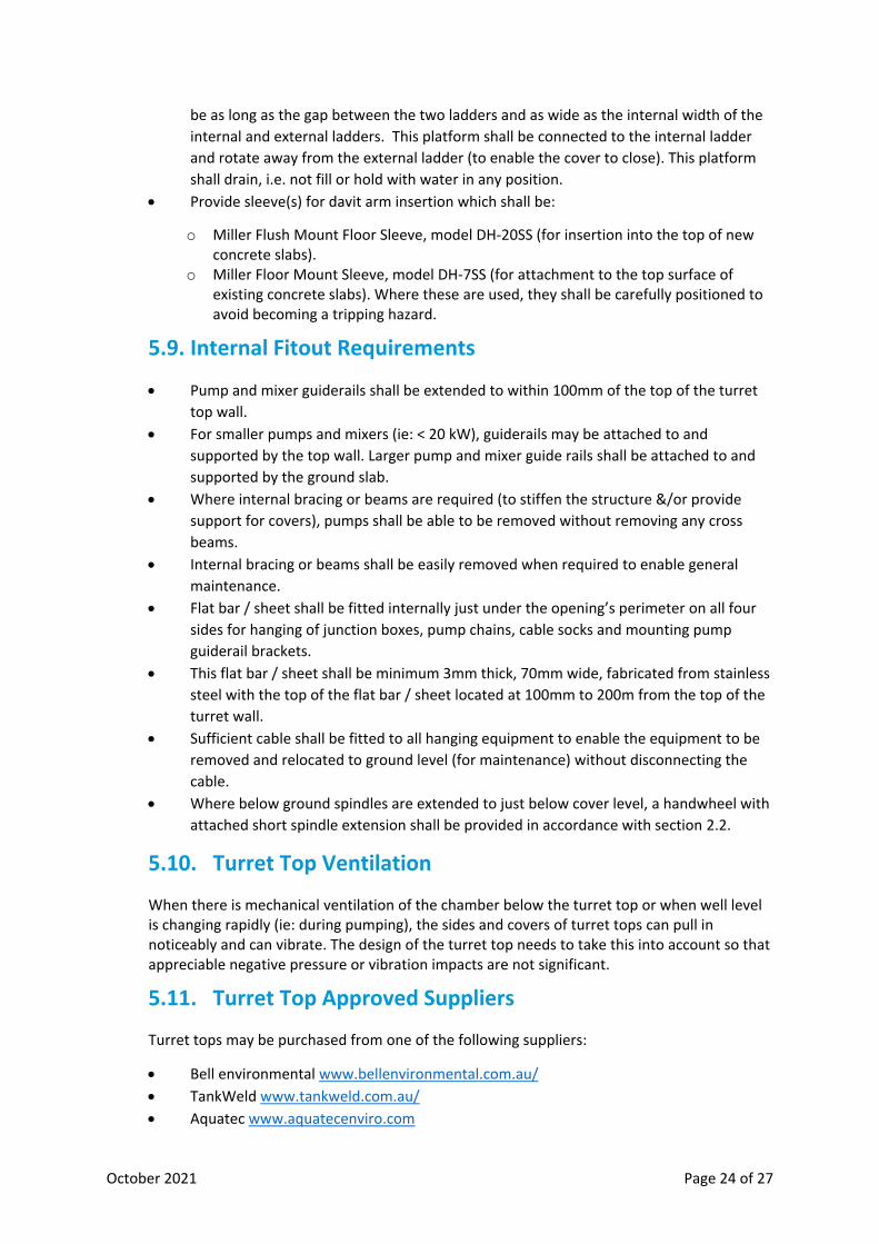
5.9. Internal Fitout Requirements
• Pump and mixer guiderails shall be extended to within 100mm of the top of the turret
top wall.
• For smaller pumps and mixers (ie: < 20 kW), guiderails may be attached to and
supported by the top wall. Larger pump and mixer guide rails shall be attached to and
supported by the ground slab.
• Where internal bracing or beams are required (to stiffen the structure &/or provide
support for covers), pumps shall be able to be removed without removing any cross
beams.
• Internal bracing or beams shall be easily removed when required to enable general
maintenance.
• Flat bar / sheet shall be fitted internally just under the opening’s perimeter on all four
sides for hanging of junction boxes, pump chains, cable socks and mounting pump
guiderail brackets.
• This flat bar / sheet shall be minimum 3mm thick, 70mm wide, fabricated from stainless
steel with the top of the flat bar / sheet located at 100mm to 200m from the top of the
turret wall.
• Sufficient cable shall be fitted to all hanging equipment to enable the equipment to be
removed and relocated to ground level (for maintenance) without disconnecting the
cable.
• Where below ground spindles are extended to just below cover level, a handwheel with
attached short spindle extension shall be provided in accordance with section 2.2.
5.10. Turret Top Ventilation
When there is mechanical ventilation of the chamber below the turret top or when well level is changing rapidly (ie: during pumping), the sides and covers of turret tops can pull in noticeably and can vibrate. The design of the turret top needs to take this into account so that appreciable negative pressure or vibration impacts are not significant.
5.11. Turret Top Approved Suppliers
Turret tops may be purchased from one of the following suppliers:
• Bell environmental www.bellenvironmental.com.au/
• TankWeld www.tankweld.com.au/
• Aquatec www.aquatecenviro.com

October 2021 Page 25 of 27
These suppliers have constructed a number of these structures and are aware of SEW’s
requirements. Standard drawings are not available for turret tops due to the need for local
and site specific variations.
6. ASSET INFORMATION AND REGISTRATION
Installed covers must have clearly marked identification labels with South East Water registered
asset identification numbers and descriptions. The contractor shall provide the below listed
information to enable covers to be registered in South East Water’s asset register. Attributes shall
include at least:
• Location (plant area)
• Size (L x W)
• Material (Aluminium, Stainless Steel, Ductile Iron, Fibre Reinforced Polymer)
• Estimated weight of covers
• Structure being covered (eg: wet well, valve pit)
• Recommended Means of Lifting (eg: crane lift, 1 person lift, 2 person lift)
• Photographic documentation of the installed covers
7. Fibre Reinforced Polymer Cover Additional Requirements
The following additional requirements shall be provided for Fibre Reinforced Polymer (FRP) covers:
• material data information which include but not limited to chemical resistance, physical, mechanical properties and design life
• standard documentation as set out in WIMES 8.05 Appendix G – FRP/GRP Cover Specification
• mechanical property information (provided in their commercial standard product sheet, engineering data and/or laboratory test data)
• Flexural strength (MPa) of the cover
• Flexural strength (MPa) of the FRP composite material
• If the FRP cover consist of a finished gel or flow coat, provide the flexural strength (MPa) of the gel, flow coat or external moulded skin
• The contractor shall supply to SEW an additional spare cover from each manufacturing batch to be held in permanent and safe storage for subsequent testing (including post-contract and long term periods) and comparative investigations. The spares shall be wrapped in plastic bags preventing exposure to sunlight while under storage.
• Sawing or cutting of any manufactured unit or module is not preferred. However in exceptional circumstances if cutting is absolutely necessary, cutting must be done with angle grinders in compliance with the manufacturer’s requirements. Appropriate gelcoat treatment shall be applied to the exposed surfaces resulting from the cut and shall meet the requirements of the manufacturer.
October 2021 Page 26 of 27
8. APPENDIX A : COVER TYPE SELECTION MATRIX
This selection matrix is available in Excel format on request.
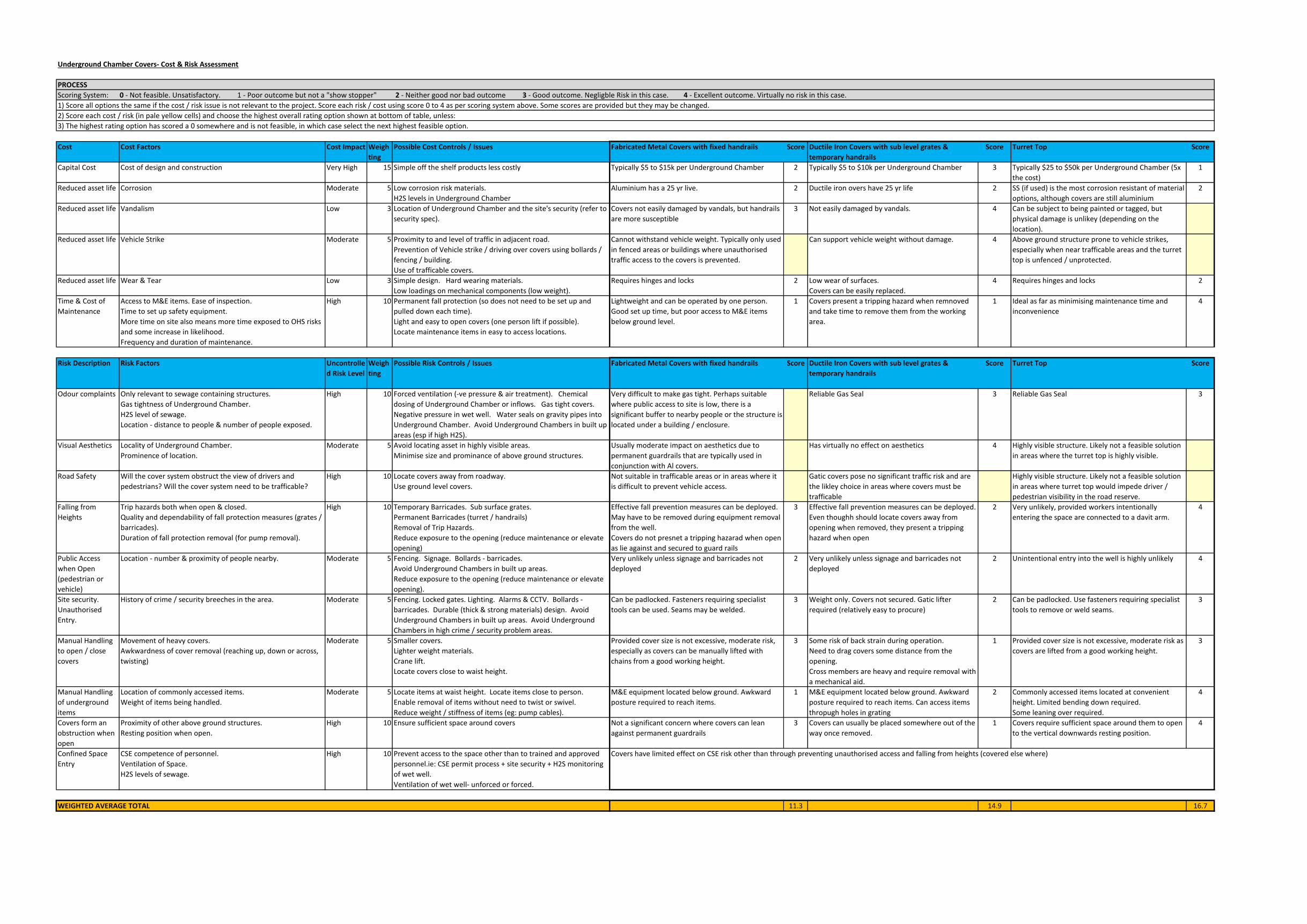
Underground Chamber Covers- Cost & Risk Assessment
PROCESS
Scoring System: 0 - Not feasible. Unsatisfactory. 1 - Poor outcome but not a "show stopper" 2 - Neither good nor bad outcome 3 - Good outcome. Negligble Risk in this case. 4 - Excellent outcome. Virtually no risk in this case.
1) Score all options the same if the cost / risk issue is not relevant to the project. Score each risk / cost using score 0 to 4 as per scoring system above. Some scores are provided but they may be changed.
2) Score each cost / risk (in pale yellow cells) and choose the highest overall rating option shown at bottom of table, unless:
3) The highest rating option has scored a 0 somewhere and is not feasible, in which case select the next highest feasible option.
Cost Cost Factors Cost Impact Weigh
ting
Possible Cost Controls / Issues Fabricated Metal Covers with fixed handrails Score Ductile Iron Covers with sub level grates &
temporary handrails
Score Turret Top Score
Capital Cost Cost of design and construction Very High 15 Simple off the shelf products less costly Typically $5 to $15k per Underground Chamber 2 Typically $5 to $10k per Underground Chamber 3 Typically $25 to $50k per Underground Chamber (5x
the cost)
1
Reduced asset life Corrosion Moderate 5 Low corrosion risk materials.
H2S levels in Underground Chamber
Aluminium has a 25 yr live. 2 Ductile iron overs have 25 yr life 2 SS (if used) is the most corrosion resistant of material
options, although covers are still aluminium
2
Reduced asset life Vandalism Low 3 Location of Underground Chamber and the site's security (refer to
security spec).
Covers not easily damaged by vandals, but handrails
are more susceptible
3 Not easily damaged by vandals. 4 Can be subject to being painted or tagged, but
physical damage is unlikey (depending on the
location).
Reduced asset life Vehicle Strike Moderate 5 Proximity to and level of traffic in adjacent road.
Prevention of Vehicle strike / driving over covers using bollards /
fencing / building.
Use of trafficable covers.
Cannot withstand vehicle weight. Typically only used
in fenced areas or buildings where unauthorised
traffic access to the covers is prevented.
Can support vehicle weight without damage. 4 Above ground structure prone to vehicle strikes,
especially when near trafficable areas and the turret
top is unfenced / unprotected.
Reduced asset life Wear & Tear Low 3 Simple design. Hard wearing materials.
Low loadings on mechanical components (low weight).
Requires hinges and locks 2 Low wear of surfaces.
Covers can be easily replaced.
4 Requires hinges and locks 2
Time & Cost of
Maintenance
Access to M&E items. Ease of inspection.
Time to set up safety equipment.
More time on site also means more time exposed to OHS risks
and some increase in likelihood.
Frequency and duration of maintenance.
High 10 Permanent fall protection (so does not need to be set up and
pulled down each time).
Light and easy to open covers (one person lift if possible).
Locate maintenance items in easy to access locations.
Lightweight and can be operated by one person.
Good set up time, but poor access to M&E items
below ground level.
1 Covers present a tripping hazard when remnoved
and take time to remove them from the working
area.
1 Ideal as far as minimising maintenance time and
inconvenience
4
Risk Description Risk Factors Uncontrolle
d Risk Level
Weigh
ting
Possible Risk Controls / Issues Fabricated Metal Covers with fixed handrails Score Ductile Iron Covers with sub level grates &
temporary handrails
Score Turret Top Score
Odour complaints Only relevant to sewage containing structures.
Gas tightness of Underground Chamber.
H2S level of sewage.
Location - distance to people & number of people exposed.
High 10 Forced ventilation (-ve pressure & air treatment). Chemical
dosing of Underground Chamber or inflows. Gas tight covers.
Negative pressure in wet well. Water seals on gravity pipes into
Underground Chamber. Avoid Underground Chambers in built up
areas (esp if high H2S).
Very difficult to make gas tight. Perhaps suitable
where public access to site is low, there is a
significant buffer to nearby people or the structure is
located under a building / enclosure.
Reliable Gas Seal 3 Reliable Gas Seal 3
Visual Aesthetics Locality of Underground Chamber.
Prominence of location.
Moderate 5 Avoid locating asset in highly visible areas.
Minimise size and prominance of above ground structures.
Usually moderate impact on aesthetics due to
permanent guardrails that are typically used in
conjunction with Al covers.
Has virtually no effect on aesthetics 4 Highly visible structure. Likely not a feasible solution
in areas where the turret top is highly visible.
Road Safety Will the cover system obstruct the view of drivers and
pedestrians? Will the cover system need to be trafficable?
High 10 Locate covers away from roadway.
Use ground level covers.
Not suitable in trafficable areas or in areas where it
is difficult to prevent vehicle access.
Gatic covers pose no significant traffic risk and are
the likley choice in areas where covers must be
trafficable
Highly visible structure. Likely not a feasible solution
in areas where turret top would impede driver /
pedestrian visibility in the road reserve.
Falling from
Heights
Trip hazards both when open & closed.
Quality and dependability of fall protection measures (grates /
barricades).
Duration of fall protection removal (for pump removal).
High 10 Temporary Barricades. Sub surface grates.
Permanent Barricades (turret / handrails)
Removal of Trip Hazards.
Reduce exposure to the opening (reduce maintenance or elevate
opening)
Effective fall prevention measures can be deployed.
May have to be removed during equipment removal
from the well.
Covers do not presnet a tripping hazarad when open
as lie against and secured to guard rails
3 Effective fall prevention measures can be deployed.
Even thoughh should locate covers away from
opening when removed, they present a tripping
hazard when open
2 Very unlikely, provided workers intentionally
entering the space are connected to a davit arm.
4
Public Access
when Open
(pedestrian or
vehicle)
Location - number & proximity of people nearby. Moderate 5 Fencing. Signage. Bollards - barricades.
Avoid Underground Chambers in built up areas.
Reduce exposure to the opening (reduce maintenance or elevate
opening).
Very unlikely unless signage and barricades not
deployed
2 Very unlikely unless signage and barricades not
deployed
2 Unintentional entry into the well is highly unlikely 4
Site security.
Unauthorised
Entry.
History of crime / security breeches in the area. Moderate 5 Fencing. Locked gates. Lighting. Alarms & CCTV. Bollards -
barricades. Durable (thick & strong materials) design. Avoid
Underground Chambers in built up areas. Avoid Underground
Chambers in high crime / security problem areas.
Can be padlocked. Fasteners requiring specialist
tools can be used. Seams may be welded.
3 Weight only. Covers not secured. Gatic lifter
required (relatively easy to procure)
2 Can be padlocked. Use fasteners requiring specialist
tools to remove or weld seams.
3
Manual Handling
to open / close
covers
Movement of heavy covers.
Awkwardness of cover removal (reaching up, down or across,
twisting)
Moderate 5 Smaller covers.
Lighter weight materials.
Crane lift.
Locate covers close to waist height.
Provided cover size is not excessive, moderate risk,
especially as covers can be manually lifted with
chains from a good working height.
3 Some risk of back strain during operation.
Need to drag covers some distance from the
opening.
Cross members are heavy and require removal with
a mechanical aid.
1 Provided cover size is not excessive, moderate risk as
covers are lifted from a good working height.
3
Manual Handling
of underground
items
Location of commonly accessed items.
Weight of items being handled.
Moderate 5 Locate items at waist height. Locate items close to person.
Enable removal of items without need to twist or swivel.
Reduce weight / stiffness of items (eg: pump cables).
M&E equipment located below ground. Awkward
posture required to reach items.
1 M&E equipment located below ground. Awkward
posture required to reach items. Can access items
thropugh holes in grating
2 Commonly accessed items located at convenient
height. Limited bending down required.
Some leaning over required.
4
Covers form an
obstruction when
open
Proximity of other above ground structures.
Resting position when open.
High 10 Ensure sufficient space around covers Not a significant concern where covers can lean
against permanent guardrails
3 Covers can usually be placed somewhere out of the
way once removed.
1 Covers require sufficient space around them to open
to the vertical downwards resting position.
4
Confined Space
Entry
CSE competence of personnel.
Ventilation of Space.
H2S levels of sewage.
High 10 Prevent access to the space other than to trained and approved
personnel.ie: CSE permit process + site security + H2S monitoring
of wet well.
Ventilation of wet well- unforced or forced.
WEIGHTED AVERAGE TOTAL 11.3 14.9 16.7
Covers have limited effect on CSE risk other than through preventing unauthorised access and falling from heights (covered else where)
October 2021 Page 27 of 27
9. APPENDIX B : COVER DESIGN ILLUSTRATIONS

SCHEMATIC ONLY
NOT TO BE USED FOR CONSTRUCTION
FIGURE A: FABRICATED METAL COVER SYSTEM- ISOMETRIC VIEWNOTES
C
DESCRIPTION
SS316LLADDER
LIFTING CHAINS
ITEM
FASTENED TO LIFTING END OF COVER AND TIED OFF AT TOP OFVERTICAL POST OF GUARDRAIL ON THE OPPOSITE SIDE. ENABLESCOVERS TO BE LIFTED FROM A STANDING POSITION
AB
ED
GF
IH
TO SEW DRAWING SEWL-STD-005
MATERIAL
SWING GATEGALVANISED WELDED LINK CHAINWITH LINKS > 2mm THICK. CARABINEERTO CLIP THROUGH LINKS
COVER SLAB
AUTO CLOSING WITH LATCH
MILLER FLUSH MOUNT SLEEVE MODEL DH-20SS
TO INCLUDE KICK PLATES. TO AS 1657PERMANENT GUARDRAILS GALVANIZED STEEL OR SS
DAVIT ARM MOUNTING SS304
REINFORCED CONCRETE OPENING SIZED TO SUIT UNDERGROUND PLANT
Notes Regarding Fabricated Metal Covers:1. This drawing is indicative only, and does not represent a fabrication or construction issue drawing.2. Each cover system needs to be individually designed so that it integrates well with the other assets
on site and enables safe and efficient operations and maintenance activities to be performed.3. These covers are non-trafficable and shall only to be used in conjunction with appropriate
measures to prevent vehicle traffic on the covers.4. These covers shall only be used in conjunction with permanent guardrails.5. These covers shall only be used where odour emissions are unlikely to be problematic.6. All dimensions in mm.
TABLE A: COMPONENTS
METAL COVER, 1ST OPEN GRADE 5052, 5083 or 6064-T6MARINE GRADE ALUMINIUM
A
B
C
D
E
F
G
H
J
METAL COVER, 2ND OPENMETAL COVER, 3RD OPEN
AS ITEM B
EACH COVER TO HAVE RECESSED HANDLE SO HANDLES DO NOT PRESENTTRIPPING HAZARD. 1ST COVER OPEN IS TO LATCH TO COVER SLAB ANDLOCK WITH STANDARD SEW LOCK. 2ND COVER TO BE HELD DOWN BY 1STCOVER, 3RD COVER BY 2ND COVER etc SO ONLY ONE LOCK REQUIRED
FIGURE B: FABRICATED METAL COVER SYSTEM- PLAN VIEW
100
> 600
100
COVER RESTRAINTS TO RESTRAIN EACH COVER TO THE GUARDRAIL WHEN OPEN, CLIPCARABINEER THROUGH A LIFTING CHAIN LINK
J
I
CARABINEER WITH SHORT SS316LEASH TO TOP OF VERTICALGUARDRAIL POST
I
APPROXIMATELOCATION OFLOCKING POINT
FIGURE C: SPINDLE EXTENSION TO DUCTILE IRON COVERED OPENING
VALVE KEYDURING
OPERATION
CHAMBER /PIT WALL
METAL COVER
SPINDLE EXTENSION
SUPPORT BRACKET
100 x 100 HOLE IN METALCOVER DIRECTLY OVERSPINDLE
~ 100
100 to200
NON HINGE EDGEOF COVER
HINGED LID WITH FINGERPULL TO COVER HOLE
(REFER FIGURE D)
FIGURE D: SPINDLE OPENINGCOVER (IN CLOSED POSITION)
MAINCOVER
MAINCOVER
SPINDLE COVER
SS FINGER PULLRECESSED INTOSPIDLE COVER
3 THICKNEOPRENEALL AROUNDOPENING
SS PIANO HINGE
> 600
AutoCAD SHX Text
H
AutoCAD SHX Text
G
AutoCAD SHX Text
F
AutoCAD SHX Text
E
AutoCAD SHX Text
D
AutoCAD SHX Text
C
AutoCAD SHX Text
B
AutoCAD SHX Text
A
AutoCAD SHX Text
12
AutoCAD SHX Text
11
AutoCAD SHX Text
10
AutoCAD SHX Text
9
AutoCAD SHX Text
8
AutoCAD SHX Text
7
AutoCAD SHX Text
6
AutoCAD SHX Text
5
AutoCAD SHX Text
4
AutoCAD SHX Text
3
AutoCAD SHX Text
2
AutoCAD SHX Text
1
AutoCAD SHX Text
12
AutoCAD SHX Text
11
AutoCAD SHX Text
10
AutoCAD SHX Text
9
AutoCAD SHX Text
8
AutoCAD SHX Text
7
AutoCAD SHX Text
6
AutoCAD SHX Text
5
AutoCAD SHX Text
4
AutoCAD SHX Text
3
AutoCAD SHX Text
2
AutoCAD SHX Text
1
AutoCAD SHX Text
OR INITIALS APPEAR PRINTED AND MARKED THUS (#) IN THE SIGNATURE BLOCKS.
AutoCAD SHX Text
THE ORIGINAL DRAWING WAS HAND SIGNED BY THE PERSON WHOSE NAME
AutoCAD SHX Text
H
AutoCAD SHX Text
G
AutoCAD SHX Text
F
AutoCAD SHX Text
E
AutoCAD SHX Text
D
AutoCAD SHX Text
C
AutoCAD SHX Text
B
AutoCAD SHX Text
A
AutoCAD SHX Text
c
AutoCAD SHX Text
SCALE:
AutoCAD SHX Text
REV
AutoCAD SHX Text
NUMERAL
AutoCAD SHX Text
DRAWING NUMBER
AutoCAD SHX Text
DATE
AutoCAD SHX Text
DESCRIPTION
AutoCAD SHX Text
ZONE
AutoCAD SHX Text
REV
AutoCAD SHX Text
PLAN TYPE:
AutoCAD SHX Text
CAD FILE NAME:
AutoCAD SHX Text
SOUTH EAST WATER CORPORATION
AutoCAD SHX Text
AutoCAD SHX Text
WatersEdge 101 Wells Street
AutoCAD SHX Text
T 61 3 9552 3000 F 61 3 9552 3001
AutoCAD SHX Text
www.sew.com.au
AutoCAD SHX Text
Frankston VIC 3199
AutoCAD SHX Text
South East Water Corporation
AutoCAD SHX Text
"THIS DOCUMENT IS AND SHALL DOCUMENT IS AND SHALL DOCUMENT IS AND SHALL IS AND SHALL IS AND SHALL AND SHALL AND SHALL SHALL SHALL REMAIN THE PROPERTY OF SOUTH THE PROPERTY OF SOUTH THE PROPERTY OF SOUTH PROPERTY OF SOUTH PROPERTY OF SOUTH OF SOUTH OF SOUTH SOUTH SOUTH EAST WATER CORPORATION. THIS WATER CORPORATION. THIS WATER CORPORATION. THIS CORPORATION. THIS CORPORATION. THIS THIS THIS DOCUMENT MAY ONLY BE USED FOR MAY ONLY BE USED FOR MAY ONLY BE USED FOR ONLY BE USED FOR ONLY BE USED FOR BE USED FOR BE USED FOR USED FOR USED FOR FOR FOR THE PURPOSE FOR WHICH IT WAS PURPOSE FOR WHICH IT WAS PURPOSE FOR WHICH IT WAS FOR WHICH IT WAS FOR WHICH IT WAS WHICH IT WAS WHICH IT WAS IT WAS IT WAS WAS WAS COMMISSIONED AND IN ACCORDANCE AND IN ACCORDANCE AND IN ACCORDANCE IN ACCORDANCE IN ACCORDANCE ACCORDANCE ACCORDANCE WITH THE TERMS OF ENGAGEMENT THE TERMS OF ENGAGEMENT THE TERMS OF ENGAGEMENT TERMS OF ENGAGEMENT TERMS OF ENGAGEMENT OF ENGAGEMENT OF ENGAGEMENT ENGAGEMENT ENGAGEMENT FOR THE COMMISSION. THIS DESIGN THE COMMISSION. THIS DESIGN THE COMMISSION. THIS DESIGN COMMISSION. THIS DESIGN COMMISSION. THIS DESIGN THIS DESIGN THIS DESIGN DESIGN DESIGN SHOULD NOT BE COPIED OR AMENDED NOT BE COPIED OR AMENDED NOT BE COPIED OR AMENDED BE COPIED OR AMENDED BE COPIED OR AMENDED COPIED OR AMENDED COPIED OR AMENDED OR AMENDED OR AMENDED AMENDED AMENDED WITHOUT WRITTEN PERMISSION FROM WRITTEN PERMISSION FROM WRITTEN PERMISSION FROM PERMISSION FROM PERMISSION FROM FROM FROM SOUTH EAST WATER. UNAUTHORISED EAST WATER. UNAUTHORISED EAST WATER. UNAUTHORISED WATER. UNAUTHORISED WATER. UNAUTHORISED UNAUTHORISED UNAUTHORISED USE OF THIS DOCUMENT IN ANY WAY OF THIS DOCUMENT IN ANY WAY OF THIS DOCUMENT IN ANY WAY THIS DOCUMENT IN ANY WAY THIS DOCUMENT IN ANY WAY DOCUMENT IN ANY WAY DOCUMENT IN ANY WAY IN ANY WAY IN ANY WAY ANY WAY ANY WAY WAY WAY IS PROHIBITED."
AutoCAD SHX Text
COPYRIGHT
AutoCAD SHX Text
200 mm
AutoCAD SHX Text
DO NOT SCALE - IF IN DOUBT, ASK
AutoCAD SHX Text
150
AutoCAD SHX Text
90
AutoCAD SHX Text
100
AutoCAD SHX Text
80
AutoCAD SHX Text
70
AutoCAD SHX Text
60
AutoCAD SHX Text
50
AutoCAD SHX Text
40
AutoCAD SHX Text
30
AutoCAD SHX Text
20
AutoCAD SHX Text
10
AutoCAD SHX Text
0
AutoCAD SHX Text
ORIGINAL SIZE
AutoCAD SHX Text
A1
AutoCAD SHX Text
DESIGNED
AutoCAD SHX Text
DES. CHK.
AutoCAD SHX Text
MELWAY REF:
AutoCAD SHX Text
APPROVED:
AutoCAD SHX Text
(FULL SIZE PLOT)
AutoCAD SHX Text
DRAWN
AutoCAD SHX Text
DRAFT CHK.
AutoCAD SHX Text
SHEET SIZE:
AutoCAD SHX Text
A
AutoCAD SHX Text
B
AutoCAD SHX Text
-
AutoCAD SHX Text
-
AutoCAD SHX Text
-
AutoCAD SHX Text
1ST REVISION
AutoCAD SHX Text
SPINDLE EXTENSION DETAIL ADDED
AutoCAD SHX Text
-
AutoCAD SHX Text
-
AutoCAD SHX Text
-
AutoCAD SHX Text
07/ 2018
AutoCAD SHX Text
08/2021
AutoCAD SHX Text
-
AutoCAD SHX Text
-
AutoCAD SHX Text
-
AutoCAD SHX Text
A3
AutoCAD SHX Text
COLIN PAXMAN
AutoCAD SHX Text
UNDERGROUND STRUCTURE COVERS SPECIFICATION
AutoCAD SHX Text
FABRICATED METAL COVERS
AutoCAD SHX Text
Sheet 1 of 3
AutoCAD SHX Text
NA
AutoCAD SHX Text
AM2757- SHEET 1
AutoCAD SHX Text
R. JAGGER
AutoCAD SHX Text
R. JAGGER
AutoCAD SHX Text
-
AutoCAD SHX Text
-
AutoCAD SHX Text
-
AutoCAD SHX Text
M. MAXWELL
AutoCAD SHX Text
J. STREET
AutoCAD SHX Text
-
AutoCAD SHX Text
-
AutoCAD SHX Text
-
AutoCAD SHX Text
R. JAGGER
AutoCAD SHX Text
R. JAGGER
AutoCAD SHX Text
-
AutoCAD SHX Text
-
AutoCAD SHX Text
-
AutoCAD SHX Text
M. MAXWELL
AutoCAD SHX Text
J. STREET
AutoCAD SHX Text
-
AutoCAD SHX Text
-
AutoCAD SHX Text
-

SCHEMATIC ONLY
NOT TO BE USED FOR CONSTRUCTION
FIGURE A: DUCTILE IRON COVER SYSTEM- ISOMETRIC VIEW
NOTES
SS316L
TO RESTRAIN EACH MESH TO THE GUARDRAIL WHEN OPEN. FIX LEASHTO MESH, FIX CARABINEER AROUND GUARDRAIL
TO SEW DRAWING SEWL-STD-005
MATERIAL
CARABINEER & SS CABLE LEASHTO STORE REMOVABLE GUARDRAIL SYSTEM. LOCKED WITH SEW LOCK
MILLER FLUSH MOUNT SLEEVE MODEL DH-20SS
TO INCLUDE KICK PLATES. TO AS 1657GALVANIZED STEEL OR SS
SS304
REINFORCED CONCRETE OPENING SIZED TO SUIT UNDERGROUND PLANT
APPROVED DI COVER
A
B
C
D
E
FG
H
AS ITEM B
NO MORE THAN ONE ROW OF COVERS PERMITTED
FIGURE B: DUCTILE IRON COVER SYSTEM- PLAN VIEW
100
100
H
I
NO OPENING GREATER THAN 200 WIDE PERMITTED. HINGED. EACH GRATE < 15 kgTO PROVIDE EASY ACCESS TO JUNCTION BOX & INSTRUMENTS. HINGED
SS316SS316
C
DESCRIPTION
LADDER
COVER RESTRAINTS
ITEMAB
ED
GF
IH STORAGE CUBICLE
COVER SLABREMOVABLE GUARDRAILS
DAVIT ARM MOUNTING
TABLE A: COMPONENTS
DUCTILE IRON COVERFALL PROTECTION MESHHATCH OVER SMALL OPENING
FIGURE C: SPINDLE EXTENSION TO DUCTILE IRON COVERED OPENING
VALVE KEYDURING
OPERATION
CHAMBER / PIT WALL
DUCTILE IRONCOVER
SPINDLE EXTENSION
Notes Regarding Ductile Iron Covers:1. This drawing is indicative only, and does not represent a fabrication or construction issue drawing.2. Each cover system needs to be individually designed so that it integrates well with the other assets on site and enables
safe and efficient operations and maintenance activities to be performed.3. These covers are for structures in trafficable areas.4. These covers shall only be used in conjunction with temporary mobile guardrails.5. All dimensions in mm.
REMOVABLE PLUG (GREASED)
SUPPORT BRACKET
FALL PROTECTION GRATEWITH HOLE AT SPINDLE
DUCTILE IRON COVER HOLE ATSPINDLE
< 50
100 to200
> 600
> 600
AutoCAD SHX Text
H
AutoCAD SHX Text
G
AutoCAD SHX Text
F
AutoCAD SHX Text
E
AutoCAD SHX Text
D
AutoCAD SHX Text
C
AutoCAD SHX Text
B
AutoCAD SHX Text
A
AutoCAD SHX Text
12
AutoCAD SHX Text
11
AutoCAD SHX Text
10
AutoCAD SHX Text
9
AutoCAD SHX Text
8
AutoCAD SHX Text
7
AutoCAD SHX Text
6
AutoCAD SHX Text
5
AutoCAD SHX Text
4
AutoCAD SHX Text
3
AutoCAD SHX Text
2
AutoCAD SHX Text
1
AutoCAD SHX Text
12
AutoCAD SHX Text
11
AutoCAD SHX Text
10
AutoCAD SHX Text
9
AutoCAD SHX Text
8
AutoCAD SHX Text
7
AutoCAD SHX Text
6
AutoCAD SHX Text
5
AutoCAD SHX Text
4
AutoCAD SHX Text
3
AutoCAD SHX Text
2
AutoCAD SHX Text
1
AutoCAD SHX Text
OR INITIALS APPEAR PRINTED AND MARKED THUS (#) IN THE SIGNATURE BLOCKS.
AutoCAD SHX Text
THE ORIGINAL DRAWING WAS HAND SIGNED BY THE PERSON WHOSE NAME
AutoCAD SHX Text
H
AutoCAD SHX Text
G
AutoCAD SHX Text
F
AutoCAD SHX Text
E
AutoCAD SHX Text
D
AutoCAD SHX Text
C
AutoCAD SHX Text
B
AutoCAD SHX Text
A
AutoCAD SHX Text
c
AutoCAD SHX Text
SCALE:
AutoCAD SHX Text
REV
AutoCAD SHX Text
NUMERAL
AutoCAD SHX Text
DRAWING NUMBER
AutoCAD SHX Text
DATE
AutoCAD SHX Text
DESCRIPTION
AutoCAD SHX Text
ZONE
AutoCAD SHX Text
REV
AutoCAD SHX Text
PLAN TYPE:
AutoCAD SHX Text
CAD FILE NAME:
AutoCAD SHX Text
SOUTH EAST WATER CORPORATION
AutoCAD SHX Text
AutoCAD SHX Text
WatersEdge 101 Wells Street
AutoCAD SHX Text
T 61 3 9552 3000 F 61 3 9552 3001
AutoCAD SHX Text
www.sew.com.au
AutoCAD SHX Text
Frankston VIC 3199
AutoCAD SHX Text
South East Water Corporation
AutoCAD SHX Text
"THIS DOCUMENT IS AND SHALL DOCUMENT IS AND SHALL DOCUMENT IS AND SHALL IS AND SHALL IS AND SHALL AND SHALL AND SHALL SHALL SHALL REMAIN THE PROPERTY OF SOUTH THE PROPERTY OF SOUTH THE PROPERTY OF SOUTH PROPERTY OF SOUTH PROPERTY OF SOUTH OF SOUTH OF SOUTH SOUTH SOUTH EAST WATER CORPORATION. THIS WATER CORPORATION. THIS WATER CORPORATION. THIS CORPORATION. THIS CORPORATION. THIS THIS THIS DOCUMENT MAY ONLY BE USED FOR MAY ONLY BE USED FOR MAY ONLY BE USED FOR ONLY BE USED FOR ONLY BE USED FOR BE USED FOR BE USED FOR USED FOR USED FOR FOR FOR THE PURPOSE FOR WHICH IT WAS PURPOSE FOR WHICH IT WAS PURPOSE FOR WHICH IT WAS FOR WHICH IT WAS FOR WHICH IT WAS WHICH IT WAS WHICH IT WAS IT WAS IT WAS WAS WAS COMMISSIONED AND IN ACCORDANCE AND IN ACCORDANCE AND IN ACCORDANCE IN ACCORDANCE IN ACCORDANCE ACCORDANCE ACCORDANCE WITH THE TERMS OF ENGAGEMENT THE TERMS OF ENGAGEMENT THE TERMS OF ENGAGEMENT TERMS OF ENGAGEMENT TERMS OF ENGAGEMENT OF ENGAGEMENT OF ENGAGEMENT ENGAGEMENT ENGAGEMENT FOR THE COMMISSION. THIS DESIGN THE COMMISSION. THIS DESIGN THE COMMISSION. THIS DESIGN COMMISSION. THIS DESIGN COMMISSION. THIS DESIGN THIS DESIGN THIS DESIGN DESIGN DESIGN SHOULD NOT BE COPIED OR AMENDED NOT BE COPIED OR AMENDED NOT BE COPIED OR AMENDED BE COPIED OR AMENDED BE COPIED OR AMENDED COPIED OR AMENDED COPIED OR AMENDED OR AMENDED OR AMENDED AMENDED AMENDED WITHOUT WRITTEN PERMISSION FROM WRITTEN PERMISSION FROM WRITTEN PERMISSION FROM PERMISSION FROM PERMISSION FROM FROM FROM SOUTH EAST WATER. UNAUTHORISED EAST WATER. UNAUTHORISED EAST WATER. UNAUTHORISED WATER. UNAUTHORISED WATER. UNAUTHORISED UNAUTHORISED UNAUTHORISED USE OF THIS DOCUMENT IN ANY WAY OF THIS DOCUMENT IN ANY WAY OF THIS DOCUMENT IN ANY WAY THIS DOCUMENT IN ANY WAY THIS DOCUMENT IN ANY WAY DOCUMENT IN ANY WAY DOCUMENT IN ANY WAY IN ANY WAY IN ANY WAY ANY WAY ANY WAY WAY WAY IS PROHIBITED."
AutoCAD SHX Text
COPYRIGHT
AutoCAD SHX Text
200 mm
AutoCAD SHX Text
DO NOT SCALE - IF IN DOUBT, ASK
AutoCAD SHX Text
150
AutoCAD SHX Text
90
AutoCAD SHX Text
100
AutoCAD SHX Text
80
AutoCAD SHX Text
70
AutoCAD SHX Text
60
AutoCAD SHX Text
50
AutoCAD SHX Text
40
AutoCAD SHX Text
30
AutoCAD SHX Text
20
AutoCAD SHX Text
10
AutoCAD SHX Text
0
AutoCAD SHX Text
ORIGINAL SIZE
AutoCAD SHX Text
A1
AutoCAD SHX Text
DESIGNED
AutoCAD SHX Text
DES. CHK.
AutoCAD SHX Text
MELWAY REF:
AutoCAD SHX Text
APPROVED:
AutoCAD SHX Text
(FULL SIZE PLOT)
AutoCAD SHX Text
DRAWN
AutoCAD SHX Text
DRAFT CHK.
AutoCAD SHX Text
SHEET SIZE:
AutoCAD SHX Text
A
AutoCAD SHX Text
B
AutoCAD SHX Text
-
AutoCAD SHX Text
-
AutoCAD SHX Text
-
AutoCAD SHX Text
1ST REVISION
AutoCAD SHX Text
SPINDLE EXTENSION DETAIL ADDED
AutoCAD SHX Text
-
AutoCAD SHX Text
-
AutoCAD SHX Text
-
AutoCAD SHX Text
07/ 2018
AutoCAD SHX Text
08/ 2021
AutoCAD SHX Text
-
AutoCAD SHX Text
-
AutoCAD SHX Text
-
AutoCAD SHX Text
A3
AutoCAD SHX Text
COLIN PAXMAN
AutoCAD SHX Text
UNDERGROUND STRUCTURE COVERS SPECIFICATION
AutoCAD SHX Text
DUCTILE IRON COVERS
AutoCAD SHX Text
Sheet 2 of 3
AutoCAD SHX Text
NA
AutoCAD SHX Text
AM2757- SHEET 2
AutoCAD SHX Text
R. JAGGER
AutoCAD SHX Text
R. JAGGER
AutoCAD SHX Text
-
AutoCAD SHX Text
-
AutoCAD SHX Text
-
AutoCAD SHX Text
M. MAXWELL
AutoCAD SHX Text
J. STREET
AutoCAD SHX Text
-
AutoCAD SHX Text
-
AutoCAD SHX Text
-
AutoCAD SHX Text
R. JAGGER
AutoCAD SHX Text
R. JAGGER
AutoCAD SHX Text
-
AutoCAD SHX Text
-
AutoCAD SHX Text
-
AutoCAD SHX Text
M. MAXWELL
AutoCAD SHX Text
J. STREET
AutoCAD SHX Text
-
AutoCAD SHX Text
-
AutoCAD SHX Text
-

ROLL ON - ROLL OFF COVERS ARE AN ALTERNATIVE TO SWING COVERSWHERE COVER WEIGHTS ARE EXCESSIVE
SCHEMATIC ONLY
NOT TO BE USED FOR CONSTRUCTION
FIGURE A: TURRET TOP COVER SYSTEM- ISOMETRIC VIEW
C SS316LLADDER
AB
ED
G
H
TOSEW DRAWING SEWL-STD-005
COVER HANDLE SS316
COVER SLAB
PROVIDES EDGE OVER WHICH TO HANG CHAINS, INSTRUMENT LINES,JUNCTION BOXES etc
MILLER FLUSH MOUNT SLEEVE MODEL DH-20SS
TURRET TOP WALLS > 3MM THICK STAINLESS STEEL
DAVIT ARM MOUNTING SS304
REINFORCED CONCRETE OPENING SIZED TO SUIT UNDERGROUND PLANT
Notes Regarding Turret Top Covers:1. This drawing is indicative only, and does not represent a fabrication or construction issue drawing.2. Each cover system needs to be individually designed so that it integrates well with the other assets on site and enables
safe and efficient operations and maintenance activities to be performed.
TABLE A: COMPONENTS
ALUMINIUM COVER GRADE 5052, 5083 or 6064-T6MARINE GRADE ALUMINIUME
G
H
SS316
FIGURE B: TURRET TOP COVER SYSTEM- SECTION VIEW
F
AD
BC
REQUIRE AT LEAST 1m WIDE PAVEDAREA ALL THE WAY AROUND THETURRET TOP, ALL AT THE SAME LEVEL
H
F PLATFORM SS316HANGING BRACKET
NOTESITEM MATERIALDESCRIPTION
FIGURE C: SPINDLE EXTENSION TO TURRET TOP OPENING
HANDWHEEL LOCATIONDURING OPERATION
TURRET TOP WALL
TURRET TOPCOVER
HANDWHEEL LOCATIONWHEN COVER CLOSED
HANDWHEELRESTRAINT LEASH
100 to 200
100 to200
AutoCAD SHX Text
H
AutoCAD SHX Text
G
AutoCAD SHX Text
F
AutoCAD SHX Text
E
AutoCAD SHX Text
D
AutoCAD SHX Text
C
AutoCAD SHX Text
B
AutoCAD SHX Text
A
AutoCAD SHX Text
12
AutoCAD SHX Text
11
AutoCAD SHX Text
10
AutoCAD SHX Text
9
AutoCAD SHX Text
8
AutoCAD SHX Text
7
AutoCAD SHX Text
6
AutoCAD SHX Text
5
AutoCAD SHX Text
4
AutoCAD SHX Text
3
AutoCAD SHX Text
2
AutoCAD SHX Text
1
AutoCAD SHX Text
12
AutoCAD SHX Text
11
AutoCAD SHX Text
10
AutoCAD SHX Text
9
AutoCAD SHX Text
8
AutoCAD SHX Text
7
AutoCAD SHX Text
6
AutoCAD SHX Text
5
AutoCAD SHX Text
4
AutoCAD SHX Text
3
AutoCAD SHX Text
2
AutoCAD SHX Text
1
AutoCAD SHX Text
OR INITIALS APPEAR PRINTED AND MARKED THUS (#) IN THE SIGNATURE BLOCKS.
AutoCAD SHX Text
THE ORIGINAL DRAWING WAS HAND SIGNED BY THE PERSON WHOSE NAME
AutoCAD SHX Text
H
AutoCAD SHX Text
G
AutoCAD SHX Text
F
AutoCAD SHX Text
E
AutoCAD SHX Text
D
AutoCAD SHX Text
C
AutoCAD SHX Text
B
AutoCAD SHX Text
A
AutoCAD SHX Text
c
AutoCAD SHX Text
SCALE:
AutoCAD SHX Text
REV
AutoCAD SHX Text
NUMERAL
AutoCAD SHX Text
DRAWING NUMBER
AutoCAD SHX Text
DATE
AutoCAD SHX Text
DESCRIPTION
AutoCAD SHX Text
ZONE
AutoCAD SHX Text
REV
AutoCAD SHX Text
PLAN TYPE:
AutoCAD SHX Text
CAD FILE NAME:
AutoCAD SHX Text
SOUTH EAST WATER CORPORATION
AutoCAD SHX Text
AutoCAD SHX Text
WatersEdge 101 Wells Street
AutoCAD SHX Text
T 61 3 9552 3000 F 61 3 9552 3001
AutoCAD SHX Text
www.sew.com.au
AutoCAD SHX Text
Frankston VIC 3199
AutoCAD SHX Text
South East Water Corporation
AutoCAD SHX Text
"THIS DOCUMENT IS AND SHALL DOCUMENT IS AND SHALL DOCUMENT IS AND SHALL IS AND SHALL IS AND SHALL AND SHALL AND SHALL SHALL SHALL REMAIN THE PROPERTY OF SOUTH THE PROPERTY OF SOUTH THE PROPERTY OF SOUTH PROPERTY OF SOUTH PROPERTY OF SOUTH OF SOUTH OF SOUTH SOUTH SOUTH EAST WATER CORPORATION. THIS WATER CORPORATION. THIS WATER CORPORATION. THIS CORPORATION. THIS CORPORATION. THIS THIS THIS DOCUMENT MAY ONLY BE USED FOR MAY ONLY BE USED FOR MAY ONLY BE USED FOR ONLY BE USED FOR ONLY BE USED FOR BE USED FOR BE USED FOR USED FOR USED FOR FOR FOR THE PURPOSE FOR WHICH IT WAS PURPOSE FOR WHICH IT WAS PURPOSE FOR WHICH IT WAS FOR WHICH IT WAS FOR WHICH IT WAS WHICH IT WAS WHICH IT WAS IT WAS IT WAS WAS WAS COMMISSIONED AND IN ACCORDANCE AND IN ACCORDANCE AND IN ACCORDANCE IN ACCORDANCE IN ACCORDANCE ACCORDANCE ACCORDANCE WITH THE TERMS OF ENGAGEMENT THE TERMS OF ENGAGEMENT THE TERMS OF ENGAGEMENT TERMS OF ENGAGEMENT TERMS OF ENGAGEMENT OF ENGAGEMENT OF ENGAGEMENT ENGAGEMENT ENGAGEMENT FOR THE COMMISSION. THIS DESIGN THE COMMISSION. THIS DESIGN THE COMMISSION. THIS DESIGN COMMISSION. THIS DESIGN COMMISSION. THIS DESIGN THIS DESIGN THIS DESIGN DESIGN DESIGN SHOULD NOT BE COPIED OR AMENDED NOT BE COPIED OR AMENDED NOT BE COPIED OR AMENDED BE COPIED OR AMENDED BE COPIED OR AMENDED COPIED OR AMENDED COPIED OR AMENDED OR AMENDED OR AMENDED AMENDED AMENDED WITHOUT WRITTEN PERMISSION FROM WRITTEN PERMISSION FROM WRITTEN PERMISSION FROM PERMISSION FROM PERMISSION FROM FROM FROM SOUTH EAST WATER. UNAUTHORISED EAST WATER. UNAUTHORISED EAST WATER. UNAUTHORISED WATER. UNAUTHORISED WATER. UNAUTHORISED UNAUTHORISED UNAUTHORISED USE OF THIS DOCUMENT IN ANY WAY OF THIS DOCUMENT IN ANY WAY OF THIS DOCUMENT IN ANY WAY THIS DOCUMENT IN ANY WAY THIS DOCUMENT IN ANY WAY DOCUMENT IN ANY WAY DOCUMENT IN ANY WAY IN ANY WAY IN ANY WAY ANY WAY ANY WAY WAY WAY IS PROHIBITED."
AutoCAD SHX Text
COPYRIGHT
AutoCAD SHX Text
200 mm
AutoCAD SHX Text
DO NOT SCALE - IF IN DOUBT, ASK
AutoCAD SHX Text
150
AutoCAD SHX Text
90
AutoCAD SHX Text
100
AutoCAD SHX Text
80
AutoCAD SHX Text
70
AutoCAD SHX Text
60
AutoCAD SHX Text
50
AutoCAD SHX Text
40
AutoCAD SHX Text
30
AutoCAD SHX Text
20
AutoCAD SHX Text
10
AutoCAD SHX Text
0
AutoCAD SHX Text
ORIGINAL SIZE
AutoCAD SHX Text
A1
AutoCAD SHX Text
DESIGNED
AutoCAD SHX Text
DES. CHK.
AutoCAD SHX Text
MELWAY REF:
AutoCAD SHX Text
APPROVED:
AutoCAD SHX Text
(FULL SIZE PLOT)
AutoCAD SHX Text
DRAWN
AutoCAD SHX Text
DRAFT CHK.
AutoCAD SHX Text
SHEET SIZE:
AutoCAD SHX Text
A
AutoCAD SHX Text
B
AutoCAD SHX Text
-
AutoCAD SHX Text
-
AutoCAD SHX Text
-
AutoCAD SHX Text
1ST REVISION
AutoCAD SHX Text
HAND WHEEL DETAIL ADDED
AutoCAD SHX Text
-
AutoCAD SHX Text
-
AutoCAD SHX Text
-
AutoCAD SHX Text
07/ 2018
AutoCAD SHX Text
08/ 2021
AutoCAD SHX Text
-
AutoCAD SHX Text
-
AutoCAD SHX Text
-
AutoCAD SHX Text
A3
AutoCAD SHX Text
COLIN PAXMAN
AutoCAD SHX Text
UNDERGROUND STRUCTURE COVERS SPECIFICATION
AutoCAD SHX Text
TURRET TOP COVER SYSTEM
AutoCAD SHX Text
Sheet 3 of 3
AutoCAD SHX Text
NA
AutoCAD SHX Text
COVER - T.T
AutoCAD SHX Text
R. JAGGER
AutoCAD SHX Text
R. JAGGER
AutoCAD SHX Text
-
AutoCAD SHX Text
-
AutoCAD SHX Text
-
AutoCAD SHX Text
M. MAXWELL
AutoCAD SHX Text
J. STREET
AutoCAD SHX Text
-
AutoCAD SHX Text
-
AutoCAD SHX Text
-
AutoCAD SHX Text
R. JAGGER
AutoCAD SHX Text
R. JAGGER
AutoCAD SHX Text
-
AutoCAD SHX Text
-
AutoCAD SHX Text
-
AutoCAD SHX Text
M. MAXWELL
AutoCAD SHX Text
J. STREET
AutoCAD SHX Text
-
AutoCAD SHX Text
-
AutoCAD SHX Text
-