ALWAYS AT YOUR C OMMAND Models … 1022/1024/1042 GARAGE DOOR OPENERS Includes INTELLICODE® Remote...
30
Models 1022/1024/1042 GARAGE DOOR OPENERS Includes INTELLICODE ® Remote Control Safe-T-Beam ® System must be installed to close door. For use only with sectional doors. Your Residential Opener comes with a Rail Assembly which is standard for up to a 7 foot high door. Homelink ® and Car2U ® compatible For Answers and Assistance: 1.800.354.3643 or visit www.geniecompany.com SAVE THIS MANUAL FOR FUTURE REFERENCE Installer: Leave this manual with homeowner. PN# 3642036534, 5/18/2011 REV.2 Homelink ® is a registered trademark of Johnson Controls Technology Company. Car2U ® is a registered trademark of Lear Corporation. © The Genie Company 2010. X900-745 ALWAYS AT YOUR COMMAND
Transcript of ALWAYS AT YOUR C OMMAND Models … 1022/1024/1042 GARAGE DOOR OPENERS Includes INTELLICODE® Remote...

Models 1022/1024/1042GARAGE DOOR OPENERS
Includes INTELLICODE® Remote ControlSafe-T-Beam® System must be installed to close door.
For use only with sectional doors. Your ResidentialOpener comes with a Rail Assembly which is standard for up to a 7 foot high door.
Homelink® and Car2U® compatible
For Answers and Assistance:1.800.354.3643or visit www.geniecompany.com
SAVE THIS MANUAL FOR FUTURE REFERENCE
Installer: Leave this manual with homeowner.
PN# 3642036534, 5/18/2011 REV.2
Homelink® is a registered trademark of Johnson Controls Technology Company.
Car2U® is a registered trademark of Lear Corporation.
© The Genie Company 2010. X900-745
ALWAY S AT Y O U R C O M M A N D
PN# 3642036534, 02/26/2010 REV. 12
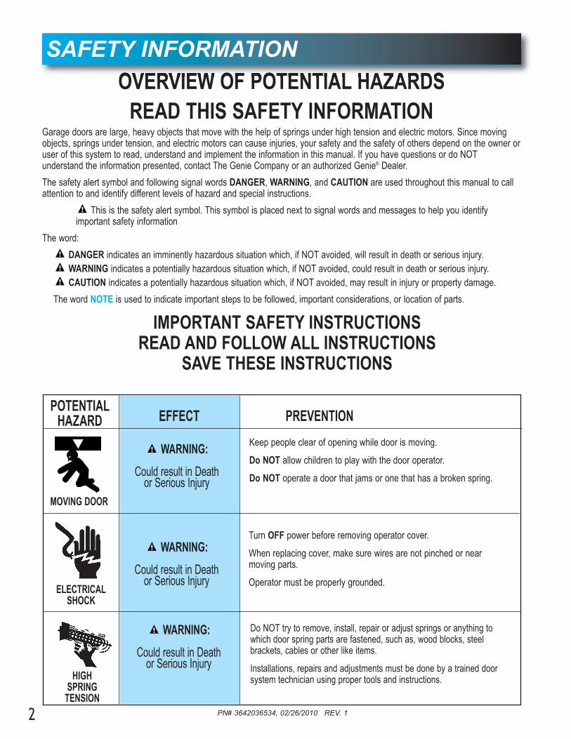
OVERVIEW OF POTENTIAL HAZARDSREAD THIS SAFETY INFORMATION
Garage doors are large, heavy objects that move with the help of springs under high tension and electric motors. Since movingobjects, springs under tension, and electric motors can cause injuries, your safety and the safety of others depend on the owner oruser of this system to read, understand and implement the information in this manual. If you have questions or do NOT understand the information presented, contact The Genie Company or an authorized Genie® Dealer.
The safety alert symbol and following signal words DANGER, WARNING, and CAUTION are used throughout this manual to callattention to and identify different levels of hazard and special instructions.
This is the safety alert symbol. This symbol is placed next to signal words and messages to help you identify important safety information
The word:
DANGER indicates an imminently hazardous situation which, if NOT avoided, will result in death or serious injury.WARNING indicates a potentially hazardous situation which, if NOT avoided, could result in death or serious injury.CAUTION indicates a potentially hazardous situation which, if NOT avoided, may result in injury or property damage.
The word NOTE is used to indicate important steps to be followed, important considerations, or location of parts.
IMPORTANT SAFETY INSTRUCTIONSREAD AND FOLLOW ALL INSTRUCTIONS
SAVE THESE INSTRUCTIONS
SAFETY INFORMATION
POTENTIAL HAZARD EFFECT PREVENTION
Keep people clear of opening while door is moving.
Do NOT allow children to play with the door operator.
Do NOT operate a door that jams or one that has a broken spring.
MOVING DOOR
WARNING:
Could result in Death or Serious Injury
Turn OFF power before removing operator cover.
When replacing cover, make sure wires are not pinched or near moving parts.
Operator must be properly grounded.ELECTRICAL
SHOCK
WARNING:
Could result in Death or Serious Injury
Do NOT try to remove, install, repair or adjust springs or anything towhich door spring parts are fastened, such as, wood blocks, steel brackets, cables or other like items.
Installations, repairs and adjustments must be done by a trained doorsystem technician using proper tools and instructions.HIGH
SPRINGTENSION
WARNING:
Could result in Death or Serious Injury

PN# 3642036534, 02/26/2010 REV. 1 3
TABLE OF CONTENTS OPENER FEATURESINTELLICODE® Rolling Code Security System.An electronic rolling code system that enhances the security ofthe door opener by continuously changing the access codeeach time the remote control is used. The door openerresponds to each new code only once. An access code copiedfrom a working system and tried again will not control the dooropener.
Lighted Wall Console*Operates door opener from inside garage. (Refer to section 3)
and Car2U® compatible.
Follow the Homelink® or Car2U® instructions in your carowner’s manual.
*Opener MUST be installed with the included Wall Console.
SAFETY FEATURESSafe-T-Beam® Non-Contact Reversing System**.Puts an invisible beam across the door opening. The door stopsand reverses to the full open position if anything passesthrough the beam. Red or green LED indicator lights on thepower head provide a self diagnostic code if an operationalproblem exists. (Refer to Section 10.)
Safe-T-Reverse® Contact Reversing System.Automatically stops and reverses a closing door within 2 seconds of contact with an object. (Refer to Section 6.)
Safe-T-Stop® Timed Reversed System.Automatically opens a closing door if it fails to close completelywithin 30 seconds.
Watch Dog™ Monitoring System.Monitors the Safe-T-Beam® system to ensure proper function-ality and will automatically stop and reverse a closing door if aproblem is detected.
Automatic Lighting System.One bulb lighting supplies up to 75 watts of light for saferevening exits and entries. Turns ON when door is activated andautomatically turns OFF 3 minutes later.
Manual Emergency Release.Manually releases door from door opener. Use during a powerfailure or other emergency to allow manual opening and closingof door. (Refer to Section 6.)
**Safe-T-Beam® Safety Reverse System MUST be installed to close door.
SECTION . . . . . . . . . . . . . . . . . . . . . . . . . . . . . . . . . . . . . . . . . PAGESAFETY INFORMATION . . . . . . . . . . . . . . . . . . . . . . . . . . . . . . . . . 2
OPENER FEATURES. . . . . . . . . . . . . . . . . . . . . . . . . . . . . . . . . . . . 3
SAFETY FEATURES . . . . . . . . . . . . . . . . . . . . . . . . . . . . . . . . . . . . 3
PRE-INSTALLATION CHECK LIST . . . . . . . . . . . . . . . . . . . . . . . 4-5
RECOMMENDED TOOLS . . . . . . . . . . . . . . . . . . . . . . . . . . . . . . . . 6
PARTS IDENTIFICATION . . . . . . . . . . . . . . . . . . . . . . . . . . . . . . . 6-7
KEY ILLUSTRATIONS . . . . . . . . . . . . . . . . . . . . . . . . . . . . . . . . . . . 8
SAFETY INSTALLATION INFORMATION . . . . . . . . . . . . . . . . . . . . 9
INSTALLATION1 OPENER ASSEMBLY . . . . . . . . . . . . . . . . . . . . . . . . . . . . 9-11
2 INSTALLATION . . . . . . . . . . . . . . . . . . . . . . . . . . . . . . . . 12-14
3 WALL BUTTON INSTALLATION . . . . . . . . . . . . . . . . . . . 15-16
4 SAFE-T-BEAM® SYSTEM INSTALLATION . . . . . . . . . . . 17-18
5 CONNECTING TO POWER . . . . . . . . . . . . . . . . . . . . . . . . . 19
ADJUSTMENTS6 LIMIT SWITCHES & FORCE ADJUSTMENT . . . . . . . . . 20-22
KEYED EMERGENCY RELEASE . . . . . . . . . . . . . . . . . . . . 21CONTACT REVERSE TEST. . . . . . . . . . . . . . . . . . . . . . . . . 22
7 PROGRAMMING REMOTE CONTROLS. . . . . . . . . . . . . . . 23
8 BATTERY/VISOR CLIP INSTALLATION . . . . . . . . . . . . . . . 24
9 LIGHT BULB AND LENS INSTALLATION . . . . . . . . . . . . . . 24
SAFETY INSTRUCTIONS . . . . . . . . . . . . . . . . . . . . . . . . . . . . . . . 25
MAINTENANCE & TROUBLESHOOTING10 ROUTINE MONTHLY MAINTENANCE . . . . . . . . . . . . . . . . 25
WIRING DIAGRAM . . . . . . . . . . . . . . . . . . . . . . . . . . . . . . . 26TROUBLESHOOTING GUIDE - OPENER. . . . . . . . . . . . . . 27TROUBLESHOOTING GUIDE - POWER HEAD LED . . . . . 28
TRANSMITTER COMPLIANCE STATEMENT . . . . . . . . . . . . . . . 29
WARRANTY . . . . . . . . . . . . . . . . . . . . . . . . . . . . . . . . . . . . . . . . . . 30

PN# 3642036534, 02/26/2010 REV. 1
6 To avoid damage to your door and/or opener, make sure you disable and/or
remove any door locks, ropes, and/or cables(NOT door lift cables) prior to installing youropener. (Refer to Section 1.)
4
PRE-INSTALLATION CHECK LIST FOR HELP-1.800.354.3643 OR WWW.GENIECOMPANY.COM
Things to consider if you are planning to "Do-it-yourself."This opener is designed for use with SECTIONAL doors only.In many cases you will be replacing an existing door opener with a new one, however, if thiswill be the first opener installed there are some pre-installation issues which need to beaddressed. They are as follows:The Genie Company recommends that you read and fully understand all information andinstructions contained herein before choosing a "Do-it-yourself" installation. Any questions should be directed to The Genie Company or an authorized Genie® Dealer.
1 Check your ceiling where the power head of your new unit will be mounted.
Plan how you will be mounting the power head.It is possible that ceiling joists may not be in theposition needed with respect to the garage dooropener. It may be necessary to add an additional bracket and fasteners (not includedwith your new door opener kit). (Refer to Section 2.)
2 Check the wall directly above the garagedoor. The door opener’s header bracket
must be securely fastened to this wall. Insurethat the structure will provide a strong mountinglocation. (Refer to Section 2.)
3 Check to see if the mounting location for the Safe-T-Beam® System is clear from
obstruction and has a wood surface availablefor attaching the mounting brackets. The brackets may be attached to concrete if necessarybut extra tools and special fasteners (not supplied)will be required. (Refer to Section 4 and 5.)
NOTE: Mounting brackets must be installedwithin code specifications.
4 Is your sectional garage door made of aluminum, light-weight steel, fiberglass
or glass panels? Additional support bracingmust be added to these type doors. If this is thecase, please contact the door manufacturer or authorized dealer so that they can furnish youwith a "bracing kit." (Refer to Section 2.)
7 Insure that your door is properly balanced and moving freely. (Refer to Section 2.)
If your door jams, binds, is improperly balanced or has a broken spring, have itrepaired or adjusted by a trained door systemtechnician. Door springs, cables, pulleys,brackets and associated hardware are underextreme tension and can cause serious injuryor death.
WARNING
(The issue numbers below refer to the circled numbers in the illustrations on page 5.)
8 (NOT SHOWN) If your garage does not havea separate entry door, you should consider
an emergency release kit (GER-2) for installation onyour garage door. (See emergency release kitinstallation notes on page 21.)
DO NOT USE AN EXTENSION CORD!DO NOT USE A PORTABLE GENERATOR! Thisproduct is designed to operate on standard house current. DO NOT USE ALTERNATE POWER SUPPLIES.
WARNING
5 You need a properly grounded 110-120 Volt power supply available. The outlet should be
no more than 3 feet from the power head once it ismounted. (Refer to Section 5.)
Remove
Remove
To reduce the risk of injury to persons ordamage to property - Use this opener onlywith sectional doors.
WARNING

PN# 3642036534, 02/26/2010 REV. 1 5
TYPICAL SECTIONAL DOOR INSTALLATION FOR HELP-1.800.354.3643 OR WWW.GENIECOMPANY.COM
TYPICAL SUPPORTBRACKET
(NOT PROVIDED)
EXTENSION SPRINGOR
TORSION SPRING
SAFE-T-BEAM®
BRACES
ADDEDHEADER BRACKETMOUNTING BOARD
POWER CORD(APPROX. 45 IN.)
TO 120V GROUNDEDOUTLET
4
1
36
2
3
5
SECTIONAL DOOR
Pg. 19 Pg. 13Pg. 12-13
Pg. 14
Pg. 11
Pg. 17-18 Pg. 17-18
MAX. 6"MIN. 5"
Pg. 12
To reduce the risk of injury to persons ordamage to property - Use this opener onlywith sectional doors.
WARNING
7
NOTE: This opener is designed foruse with SECTIONAL doors only.

PN# 3642036534, 02/26/2010 REV. 16
RECOMMENDED TOOLS FOR HELP-1.800.354.3643 OR WWW.GENIECOMPANY.COM
3/16" Drill Bit
1/4", 7/16", 3/8" and1/2" Sockets
Step ladder
Drill
Ratchet
Carpenter’s levelPencil
Tape measure
Wire strippers
Phillips screwdriver
Adjustable wrench
PARTS IDENTIFICATION - Not Shown Full Size .
Three-buttonRemote Control
Child can be pinned under automatic garage door.Death or serious injury can result.
•Never let ch ld walk or run under moving door..•Never let ch ld use door opener controls.•Always keep moving door in sight.• If person is pinned, push control button or use emergency release.•Test door opener monthly:
Re e to you owne s manual ace - nch ob ect (o 2x4 aid a ) on oo I doo a ls to eve se on con act ad ust opene I opene s ill a ls to eve se doo epai o ep ace opene
Do not emove o paint ove h s labelMount wa l cont ol out o ch ld s each at east 5 eet above loo )
ace next o wall cont ol © 999
Wall Console
Safety Brochures Entrapment WarningLabel
Safe-T-Beam® Source with wire
(Red LED)
Safe-T-Beam® Sensorwith wire
(Green LED)Wire
Insulated Staple
Door Bracket
Header Bracket
Rail Section ClampSafe-T-Beam®
Source/Sensor Bracket
ARRANGING BOX CONTENTS FOR ASSEMBLYORGANISATION DU CONTENU DE LA BOÎTE POUR LE MONTAGE
DISPOS CIÓN DEL CONTEN DO DE LA BOLSA PARA EL MONTA E
Remove i te nal box snl ve l s bo t s i t rn s
Qu e l s c ja i te nas
A range hree sma l box s for e sy acc ssAr a ger es r is e i es b î es de m ni re à ou
vo r y a cé er ac ement
D ponga a t es c j s pe ueñ s pa a t ne ac esofá il
Ar ange ra s in ine and pu l p ast c s eeve o� cha nr ang r es a ls n l gne t t er ur e man hon en p a t que
our e d gag r de a ch îne
D spo ga os r e e en l n a y es re a c m s de p ás co f erade a c dena
R move ens Box and motor power h adE l ver a bo e des e t l es t a t te mo or ée
Q i e la a a de a l nte y l mo or de a c ja e con ol
Ca efu y emove th rd r il wi h ha n tt ched) a d p ace on �oor
E le er o gne seme t e t o s ème r i ( vec ach î e at a hée et e p a er ur e sol
Cu dados men e qui e el t rcer el ( on acade a cop ada) y ponga en el p so
R move ai sec i ns not conne tedo cha n
n ev r l s s c io s de a l non onn c éesà la ha ne
Q i e as s c io es de i l no one t das aa c dena
Fo low nst uct ons n he nsta la ion Manual for a sembly tepsProc der se on l s in tru t ons s ipu ées da s le m nuel d nst l at on pour es ét pes de
montage à su v e
Box Contents Sheet
Head Rail (Chain) Section
Center Rail Section
End Rail Section
Door Arm
HammerSafety Glasses
Head Rail (Belt) Section
Pro Rail (Chain) Section
Pro Rail (Belt) Section
OR
PN# 3642036534, 02/26/2010 REV. 1
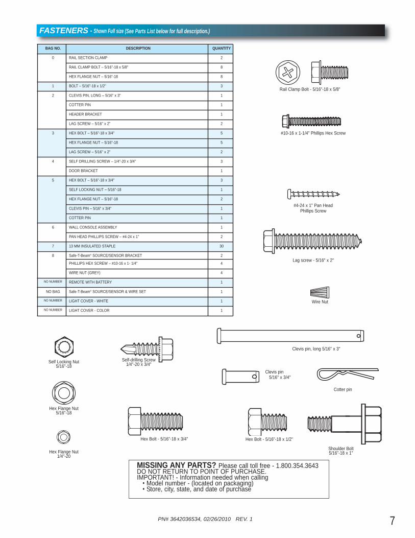
FASTENERS - Shown Full size (See Parts List below for full description.)
Lag screw - 5/16" x 2"
Self-drilling Screw1/4"-20 x 3/4"
Hex Flange Nut1/4"-20
Cotter pin
Clevis pin5/16" x 3/4"
Hex Bolt - 5/16"-18 x 3/4"
Hex Flange Nut5/16"-18
Rail Clamp Bolt - 5/16"-18 x 5/8"
#10-16 x 1-1/4" Phillips Hex Screw
Hex Bolt - 5/16"-18 x 1/2"
#4-24 x 1" Pan HeadPhillips Screw
Clevis pin, long 5/16" x 3"
7
BAG NO. DESCRIPTION QUANTITY
0 RAIL SECTION CLAMP 2
RAIL CLAMP BOLT – 5/16''-18 x 5/8'' 8
HEX FLANGE NUT – 5/16''-18 8
1 BOLT – 5/16''-18 x 1/2'' 3
2 CLEVIS PIN, LONG – 5/16" x 3" 1
COTTER PIN 1
HEADER BRACKET 1
LAG SCREW – 5/16'' x 2'' 2
3 HEX BOLT – 5/16''-18 x 3/4'' 5
HEX FLANGE NUT – 5/16''-18 5
LAG SCREW – 5/16'' x 2'' 2
4 SELF DRILLING SCREW – 1/4''-20 x 3/4'' 3
DOOR BRACKET 1
5 HEX BOLT – 5/16''-18 x 3/4'' 3
SELF LOCKING NUT – 5/16''-18 1
HEX FLANGE NUT – 5/16''-18 2
CLEVIS PIN – 5/16" x 3/4" 1
COTTER PIN 1
6 WALL CONSOLE ASSEMBLY 1
PAN HEAD PHILLIPS SCREW – #4-24 x 1'' 2
7 13 MM INSULATED STAPLE 30
8 Safe-T-Beam® SOURCE/SENSOR BRACKET 2
PHILLIPS HEX SCREW – #10-16 x 1- 1/4'' 4
WIRE NUT (GREY) 4
NO NUMBER REMOTE WITH BATTERY 1
NO BAG Safe-T-Beam® SOURCE/SENSOR & WIRE SET 1
NO NUMBER LIGHT COVER - WHITE 1
NO NUMBER LIGHT COVER - COLOR 1
Self Locking Nut5/16"-18
Wire Nut
MISSING ANY PARTS? Please call toll free - 1.800.354.3643 DO NOT RETURN TO POINT OF PURCHASE. IMPORTANT! - Information needed when calling• Model number - (located on packaging)• Store, city, state, and date of purchase
Shoulder Bolt 5/16"-18 x 1"
PN# 3642036534, 02/26/2010 REV. 18
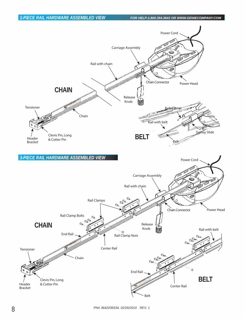
1-PIECE RAIL HARDWARE ASSEMBLED VIEW FOR HELP-1.800.354.3643 OR WWW.GENIECOMPANY.COM
3-PIECE RAIL HARDWARE ASSEMBLED VIEW
Tensioner
Rail with chain
Chain
Chain Connector
Release Knob
Header Bracket
Power Head
Power Cord
Carriage Assembly
Clevis Pin, Long & Cotter Pin
NT
S me doo s e d
brang Con act
oo dt bu o o
mnu
c u e f r
tt
s
H GH SPR NG TENSION
Can Cuse Serio
s I jury o Dea h
epr o
aju
tmen s mu t
e mde y a a n d
e ve p
s n n
o
n
sc
s
Rail with belt
Belt
Trolley Slide
Belt Clamp
Rail Clamps
Rail Clamp Bolts
Rail Clamp Nuts
Tensioner
Rail with chain
Center Rail
End Rail
Chain
Release Knob
Header Bracket
Clevis Pin, Long & Cotter Pin
Power Head
Power Cord
O
Some dor n
ed
bc ng Co
tact
or
i r bt r
r
manfac u
r or
n
H GH SPR NG TENS ON
Can Cuse Se i us njury r D
eath
Reair o
au tm
en m
u t e m
de y a t aed
v p
s
e
o n
st
ns
Rail with belt
Center Rail
End Rail
Belt
OE
Sme d
o s ee
r cg Co
tat
dor
si u o o
maufa
t r r for
o
HIGH SPRING TENSION
Cn au e Ser ous n u y or D
ea h
ea
s or djume
ts mu
be md
by a rai e
re
o s
g
o a
nu
n
CHAIN
CHAIN
BELT
BELT
Chain Connector
Carriage Assembly

PN# 3642036534, 02/26/2010 REV. 1 9
PENER ASSEMBLY FOR HELP-1.800.354.3643 OR WWW.GENIECOMPANY.COM1
NOTE: Three (3) piece rail assemblies are for a 7foot high door. Clear a workspace area to unpack and organize boxand contents for assembly. 1. There are 4 boxes inside the carton. Each box is
numbered 1 - 4. Note that some openers will contain the same parts and be packaged withfewer boxes. Carefully remove the three internal boxes (Labeled #1, 2, and 3) and placethem on the floor for easy access (Fig. 1-1).These boxes contain assembly parts and the contents are organized by assembly tasks. Forquick reference inside the lid of each box there isa label illustrating the components inside.
2. Remove the motor power head and place it onthe floor for later use. Remove box #4 andplace it on the floor for later use.
Do NOT run until opener is fully assembled andinstructed to do so.
CAUTION
FIG. 1-1 Internal boxes.
RAIL ASSEMBLY: Use a clean, flat surface.
Rail Connectors
Rail Connector Bolts
Rail Connector Nuts
Bolts
Power head
Rail
Lag Srews
5/16" Nuts& Bolts
Header BracketBolts
Header BracketBag 2
Bag 3Bag 1
Bag 0
Box Label Example
#4
1. READ AND FOLLOW ALL SAFETY, INSTALL ATION AND OPERATION INSTRUCTIONS. (If you have questions or do not understand an instruction, call The Genie Company or an authorized Genie® Dealer.)
2. Install only on a properly balanced sectional garage door.An improperly balanced door could cause severe injury. Have a trained door system technician make repairs or adjustments to cables, spring assemblies, and other hardware before installing the opener.
3. Remove all ropes and remove or make inoperative all locks connected to the garage door before installing opener.
4. Where possible, install the door opener 7 feet or more above the floor. For products having an emergency release, mount the emergency release within reach, but at least 6 feet above the floor and avoiding contact with vehicles to avoid accidental release.
IMPORTANT INSTALLATION INSTRUCTIONSWARNING: To reduce the risk of severe injury or death:
5. Do NOT connect the opener to source of power until instructed to do so.
6. Locate the control button:• Within sight of door,• At minimum height of 5 feet so small children are not
able to reach it, and• Away from all moving parts of the door.
7. Install the Entrapment WARNING Label next to the Wall Control button in a prominent location. Install the Emergency Release Tag on or next to the emergency release.
8. After installing the opener, the door must reverse within 2 seconds when it contacts a 1-1/2 inch high object (or a2 x 4 board laid flat) on the floor.
To reduce the risk of injury to persons ordamage to property - Use this opener onlywith sectional doors.
WARNING
NOTE: For 1-piece rail—skip to POWER HEAD &RAIL ASSEMBLY.

10
FIG. 1-2 Split Rail sections.
FIG. 1-3 Split Rail assembly.
A
B
Chain RailCenter Rail
End Rail
Wire Tie(s)
Rail Assembly for CHAIN DRIVE OPENERNOTE: For split rail clamps, nuts, and boltslocate Bag 0 from Box 1.3. Remove the two rail sections that are not
connected to the chain and place them onfloor (Fig. 1-2, A).
4. Carefully remove the third rail section withchain and plastic sleeve. Place rail section onfloor and extend chain straight out (Fig. 1-2, B). Chain and rail should extendapproximately 7 feet.
5. Remove wire ties and plastic bag from chain.Leave chain extended straight out on floor.Avoid kinks in the chain by careful handling andkeeping chain flat on the floor.
6. Align the three rail sections by pulling thechain straight and wrapping it around thechain tensioner pulley (Fig. 1-3 & 1-4).
7. Attach the two rail clamps to the rail sectionjoints with (4) bolts and nuts. After both rail clamps have been assembled to the rail sections,securely tighten the bolts and nuts.
PN# 3642036534, 02/26/2010 REV. 1
Rail Clamps
Rail Clamp Bolts
Rail Clamp Nuts
Rail with chain
Center Rail
End Rail
Chain
Release Knob
Power Head
T
m d
b
C
d d
b
mf
f
G P
N
Cn a
s Sous n u y r D
eh
R
d
d
Rail with belt
Center Rail
End Rail
Belt
E
m d
C
d
b
mf
H R
N
a C
u e eus I
u
Dea h
R
d
d
Rail Assembly for BELT DRIVE OPENERNOTE: For split rail clamps, nuts, and boltslocate Bag 0 from Box 1.3. Remove the two rail sections that are not
connected to the belt and place them on floor(Fig. 1-2, A).
4. Carefully remove the third rail section withbelt. Place rail section on floor, remove ties onbelt and extend belt straight out (Fig. 1-2, B).Avoid twists and kinks in the belt by careful handling and keeping belt flat on the floor. Beltand rail should extend approximately 7 feet.
5. Align the three rail sections by pulling the beltstraight and wrapping it around the tensionerpulley (Fig. 1-3 & 1-4).
6. Attach the two rail clamps to the rail sectionjoints with (4) bolts and nuts. After both rail clamps have been assembled to the rail sections,securely tighten the bolts and nuts.
Belt Rail
Center Rail
End Rail
CHAIN DRIVE RAILS
BELT DRIVE RAILS
FIG. 1-4 Mount chain/belt to tensioner pulley.
Wrap around tensioner pulley
CHAIN
BELT
A
B
Chain Connector
Carriage Assembly
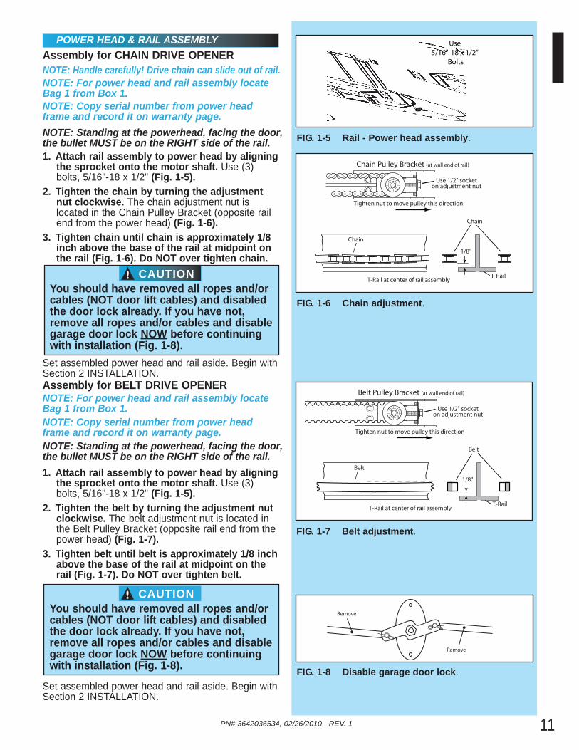
POWER HEAD & RAIL ASSEMBLYAssembly for CHAIN DRIVE OPENERNOTE: Handle carefully! Drive chain can slide out of rail.NOTE: For power head and rail assembly locateBag 1 from Box 1.NOTE: Copy serial number from power headframe and record it on warranty page.NOTE: Standing at the powerhead, facing the door, the bullet MUST be on the RIGHT side of the rail.
NOTE: Standing at the powerhead, facing the door, the bullet MUST be on the RIGHT side of the rail.
1. Attach rail assembly to power head by aligningthe sprocket onto the motor shaft. Use (3)bolts, 5/16"-18 x 1/2" (Fig. 1-5).
2. Tighten the chain by turning the adjustmentnut clockwise. The chain adjustment nut is located in the Chain Pulley Bracket (opposite railend from the power head) (Fig. 1-6).
3. Tighten chain until chain is approximately 1/8inch above the base of the rail at midpoint onthe rail (Fig. 1-6). Do NOT over tighten chain.
Set assembled power head and rail aside. Begin withSection 2 INSTALLATION.
PN# 3642036534, 02/26/2010 REV. 1 11
FIG. 1-6 Chain adjustment.
FIG. 1-5 Rail - Power head assembly.
Chain Pulley Bracket (at wall end of rail)
Chain
T-Rail at center of rail assembly
1/8"
T-Rail
Chain
Tighten nut to move pulley this direction
Use 1/2" socketon adjustment nut
Use5/16"-18 x 1/2"
Bolts
FIG. 1-8 Disable garage door lock.
Remove
Remove
FIG. 1-7 Belt adjustment.
Belt Pulley Bracket (at wall end of rail)
Belt
T-Rail at center of rail assembly
1/8"
T-Rail
Belt
Tighten nut to move pulley this direction
Use 1/2" socketon adjustment nut
Assembly for BELT DRIVE OPENERNOTE: For power head and rail assembly locateBag 1 from Box 1.NOTE: Copy serial number from power headframe and record it on warranty page.
1. Attach rail assembly to power head by aligningthe sprocket onto the motor shaft. Use (3)bolts, 5/16"-18 x 1/2" (Fig. 1-5).
2. Tighten the belt by turning the adjustment nutclockwise. The belt adjustment nut is located inthe Belt Pulley Bracket (opposite rail end from thepower head) (Fig. 1-7).
3. Tighten belt until belt is approximately 1/8 inchabove the base of the rail at midpoint on therail (Fig. 1-7). Do NOT over tighten belt.
Set assembled power head and rail aside. Begin withSection 2 INSTALLATION.
You should have removed all ropes and/orcables (NOT door lift cables) and disabledthe door lock already. If you have not,remove all ropes and/or cables and disablegarage door lock NOW before continuingwith installation (Fig. 1-8).
CAUTION
You should have removed all ropes and/orcables (NOT door lift cables) and disabledthe door lock already. If you have not,remove all ropes and/or cables and disablegarage door lock NOW before continuingwith installation (Fig. 1-8).
CAUTION
12 PN# 3642036534, 02/26/2010 REV. 1
FIG. 2-2 Finding highest point of travel.
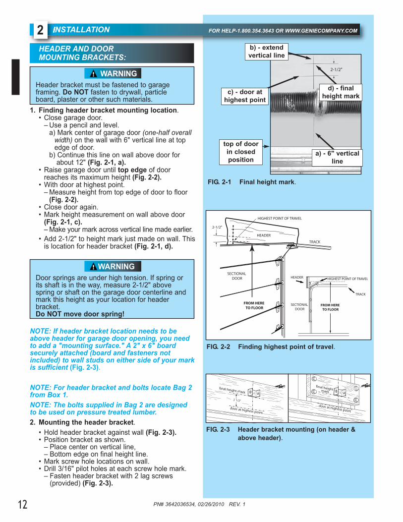
NSTALLATION FOR HELP-1.800.354.3643 OR WWW.GENIECOMPANY.COM2HEADER AND DOOR MOUNTING BRACKETS:
1. Finding header bracket mounting location.• Close garage door.
– Use a pencil and level. a) Mark center of garage door (one-half overall
width) on the wall with 6" vertical line at top edge of door.
b) Continue this line on wall above door for about 12" (Fig. 2-1, a).
• Raise garage door until top edge of door reaches its maximum height (Fig. 2-2).
• With door at highest point. – Measure height from top edge of door to floor
(Fig. 2-2).• Close door again.• Mark height measurement on wall above door
(Fig. 2-1, c).– Make your mark across vertical line made earlier.
• Add 2-1/2" to height mark just made on wall. Thisis location for header bracket (Fig. 2-1, d).
NOTE: If header bracket location needs to beabove header for garage door opening, you needto add a "mounting surface." A 2" x 6" boardsecurely attached (board and fasteners not included) to wall studs on either side of your markis sufficient (Fig. 2-3).
NOTE: For header bracket and bolts locate Bag 2from Box 1.NOTE: The bolts supplied in Bag 2 are designedto be used on pressure treated lumber.2. Mounting the header bracket.
• Hold header bracket against wall (Fig. 2-3).• Position bracket as shown.
– Place center on vertical line, – Bottom edge on final height line.
• Mark screw hole locations on wall.• Drill 3/16" pilot holes at each screw hole mark.
– Fasten header bracket with 2 lag screws (provided) (Fig. 2-3).
FIG. 2-1 Final height mark.
Header bracket must be fastened to garage framing. Do NOT fasten to drywall, particleboard, plaster or other such materials.
WARNING2-1/2"
top of doorin closedposition
d) - finalheight mark
HIGHEST POINT OF TRAVEL
TRACK
SECTIONAL DOOR
HEADER
FROM HERE TO FLOOR
2-1/2"
HIGHEST POINT OF TRAVEL
TRACK
SECTIONAL DOOR
HEADER
FROM HERE TO FLOOR
a) - 6" verticalline
b) - extend vertical line
c) - door at highest point
door at highest point
door at highest point
final height mark
final height mark
2 1/2"
FIG. 2-3 Header bracket mounting (on header & above header).
Door springs are under high tension. If spring orits shaft is in the way, measure 2-1/2" abovespring or shaft on the garage door centerline andmark this height as your location for headerbracket. Do NOT move door spring!
WARNING
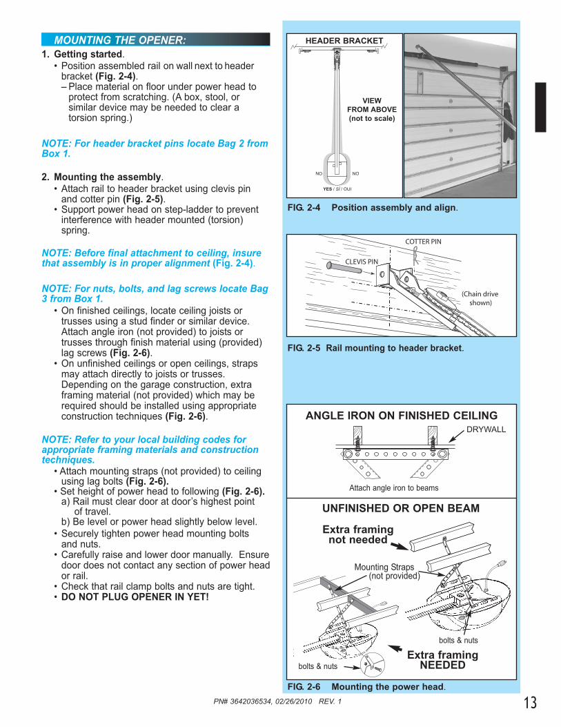
MOUNTING THE OPENER:1. Getting started.
• Position assembled rail on wall next to header bracket (Fig. 2-4).– Place material on floor under power head to
protect from scratching. (A box, stool, or similar device may be needed to clear a torsion spring.)
NOTE: For header bracket pins locate Bag 2 fromBox 1.
2. Mounting the assembly.• Attach rail to header bracket using clevis pin
and cotter pin (Fig. 2-5). • Support power head on step-ladder to prevent
interference with header mounted (torsion) spring.
NOTE: Before final attachment to ceiling, insurethat assembly is in proper alignment (Fig. 2-4).
NOTE: For nuts, bolts, and lag screws locate Bag3 from Box 1.
• On finished ceilings, locate ceiling joists or trusses using a stud finder or similar device. Attach angle iron (not provided) to joists or trusses through finish material using (provided) lag screws (Fig. 2-6).
• On unfinished ceilings or open ceilings, straps may attach directly to joists or trusses. Depending on the garage construction, extra framing material (not provided) which may be required should be installed using appropriate construction techniques (Fig. 2-6).
NOTE: Refer to your local building codes forappropriate framing materials and constructiontechniques.
• Attach mounting straps (not provided) to ceiling using lag bolts (Fig. 2-6).
• Set height of power head to following (Fig. 2-6).a) Rail must clear door at door’s highest point
of travel.b) Be level or power head slightly below level.
• Securely tighten power head mounting bolts and nuts.
• Carefully raise and lower door manually. Ensuredoor does not contact any section of power heador rail.
• Check that rail clamp bolts and nuts are tight. • DO NOT PLUG OPENER IN YET!
YES / SÍ / OUI
NONO
FIG. 2-4 Position assembly and align.
VIEW FROM ABOVE(not to scale)
HEADER BRACKET
Mounting Straps(not provided)
FIG. 2-6 Mounting the power head.
ANGLE IRON ON FINISHED CEILING
Attach angle iron to beams
UNFINISHED OR OPEN BEAM
Extra framingnot needed
Extra framingNEEDED
DRYWALL
bolts & nuts
bolts & nuts
FIG. 2-5 Rail mounting to header bracket.
COTTER PIN
CLEVIS PIN
(Chain drive shown)
PN# 3642036534, 02/26/2010 REV. 1 13

14 PN# 3642036534, 02/26/2010 REV. 1
DOOR BRACKET:
NOTE: For door bracket and bolts locate Bag 4from Box 2.1. Finding door bracket mounting location.
• Door bracket is mounted as high on door as possible along vertical centerline and NO LOWER THAN top set of rollers (Fig. 2-7).
2. Mounting the door bracket.• Proper bracing should be verified at this point.
– Align door bracket centered on your vertical centerline (Fig. 2-8).
– Attach using 3 self-drilling screws for sheet metal or other light weight material.
– Use lag screws (not provided) for solid wooden sectional doors.
NOTE: For solid wood doors, carriage bolts WITHOUT SLOTTED HEADS (not included) mayalso be used for attaching door bracket.
INSTALL DOOR ARMSNOTE: For door arm nuts and bolts, clevis andcotter pins locate Bag 5 from Box 2.1. Attach the arms.
• Fasten short branch of curved door arm to door bracket using bolt and locking nut (Fig. 2-9).
• Fasten straight arm to carriage using short clevis pin and cotter pin (Fig. 2-9).
2. Connecting the arms.• Slide carriage back and forth to adjust arm length.
– Position the straight arm 50º down from the rail.
• With the arms arranged in this position, fasten arms together using bolts and nuts spaced as far apart as possible (Fig. 2-9).
Doors made of masonite, lightweight wood, fiberglass, and sheet metal must be properlybraced before mounting door opener. Contactdoor manufacturer or distributor for a bracing kit.The Genie Company is not responsible for damage caused due to improperly braced door.
CAUTION
FIG. 2-7 Mounting door Bracket.
centerline even with or
above top roller
FIG. 2-9 Attaching door arms.
FIG. 2-8 Examples of door bracket positioning.
centerline of top roller
A B
centerline
50°
short clevis pin & cotter pin
bolts as farapart aspossible
PN# 3642036534, 02/26/2010 REV. 1
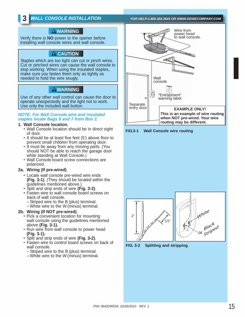
NOTE: For Wall Console, wire and insulated staples locate Bags 6 and 7 from Box 2.1. Wall Console location.
• Wall Console location should be in direct sight of door.
• It should be at least five feet (5') above floor to prevent small children from operating door.
• It must be away from any moving parts. (You should NOT be able to reach the garage door while standing at Wall Console.)
• Wall Console board screw connections are polarized.
2a. Wiring (If pre-wired).• Locate wall console pre-wired wire ends
(Fig. 3-1). (They should be located within the guidelines mentioned above.)
• Split and strip ends of wire (Fig. 3-2).• Fasten wire to wall console board screws on back of wall console.
– Striped wire to the B (plus) terminal.– White wire to the W (minus) terminal.
2b. Wiring (If NOT pre-wired).• Pick a convenient location for mounting
wall console using the guidelines mentioned above (Fig. 3-1).
• Run wire from wall console to power head (Fig. 3-1).
• Split and strip ends of wire (Fig. 3-2).• Fasten wire to control board screws on back of
wall console. – Striped wire to the B (plus) terminal.
– White wire to the (minus) terminal.
WALL CONSOLE INSTALLATION FOR HELP-1.800.354.3643 OR WWW.GENIECOMPANY.COM3
Verify there is NO power to the opener beforeinstalling wall wires and wall console.
WARNING
Staples which are too tight can cut or pinch wires.Cut or pinched wires can cause the wall console tostop working. When using the insulated staples,make sure you fasten them only as tightly as needed to hold the wire snugly.
CAUTION
FIG. 3-2 Splitting and stripping.
FIG.3-1 Wall Console wire routing
Wire from power head to wall console.
Wall console
"Entrapment"warning label
Separate entry door EXAMPLE ONLY!
This is an example of wire routing when NOT pre-wired. Your wire routing may be different.
1/2"2"
15
Use of any other wall control can cause the door tooperate unexpectedly and the light not to work.Use only the included wall button.
WARNING
BlackB
Striped
White
W
or
console
W

PN# 3642036534, 02/26/2010 REV. 116
3.Securely fasten wires. • Securely fasten wires to ceiling and
wall using insulated staples provided.– Use insulated staples.– Staples should be snug only.
• If rear cover is attached to power head, remove it.
• On power head:– Route wall console wires through wire guide on
power head. – Split and strip ends of wire (Fig. 3-2 on
previous page).– Insert wire into terminal holes and lightly press in
the orange locking clips above each terminal hole. (You can use a pencil or small screwdriver to comfortably press in locking clips.) The white wire into #1 terminal hole and striped wire into the #2 terminal hole.
– Confirm wire lock by lightly tugging on the wire. The wire should remain in the terminal hole.
• Do NOT install rear cover yet.
4. Mounting. • Fasten wall console to wall with 2 screws
(provided) (Fig. 3-4).• Remove protective backing from "Entrapment"
warning label (Fig. 3-5). The "Entrapment" label is located in the center of this manual.– Stick label on wall near wall console.
InsulatedStaple
+ –P B
Infrared Sensor
123456
FIG. 3-3 Insert wires.(Power Head With Rear Cover Removed)
1234
Terminal Holes
Locking Clips
56
wire guide
FIG. 3-4 Mounting Wall Console.
Child can be pinned under automatic garage door.
Death or serious injury can result.
•Never let child walk or run under moving door..
•Never let child use door opener controls.
•Always keep moving door in sight.
• If person is pinned, push control button or use
emergency release.
•Test door opener monthly:
Refer to your owner s manual
Place 1/ -inch object (or 2x4 laid flat) on f oor
If door fails o reverse on contact adjust opener
If opener sti l fails o reverse door repair or replace opener
Do not remove or pa nt over this label
Mount wa l con rol out of chi d s reach (at least 5 feet above floor)
Place next to wall ontrol
©1999
FIG. 3-5 Mounting Entrapment warning label.
32
1
Independent Light Control– Controls door opener lights from inside garage– Energy-Saver shut-off turns OFF lights 3 minutes after door activation
Vacation Locking Switch– LOCK disables controls after door is completely closed– UNLOCK allows controls to work normally
Door Control "Open/Close" Button– Open and closes door from inside garage
PN# 3642036534, 02/26/2010 REV. 1 17
AFE-T-BEAM® SYSTEM INSTALLATION FOR HELP-1.800.354.3643 OR WWW.GENIECOMPANY.COM4
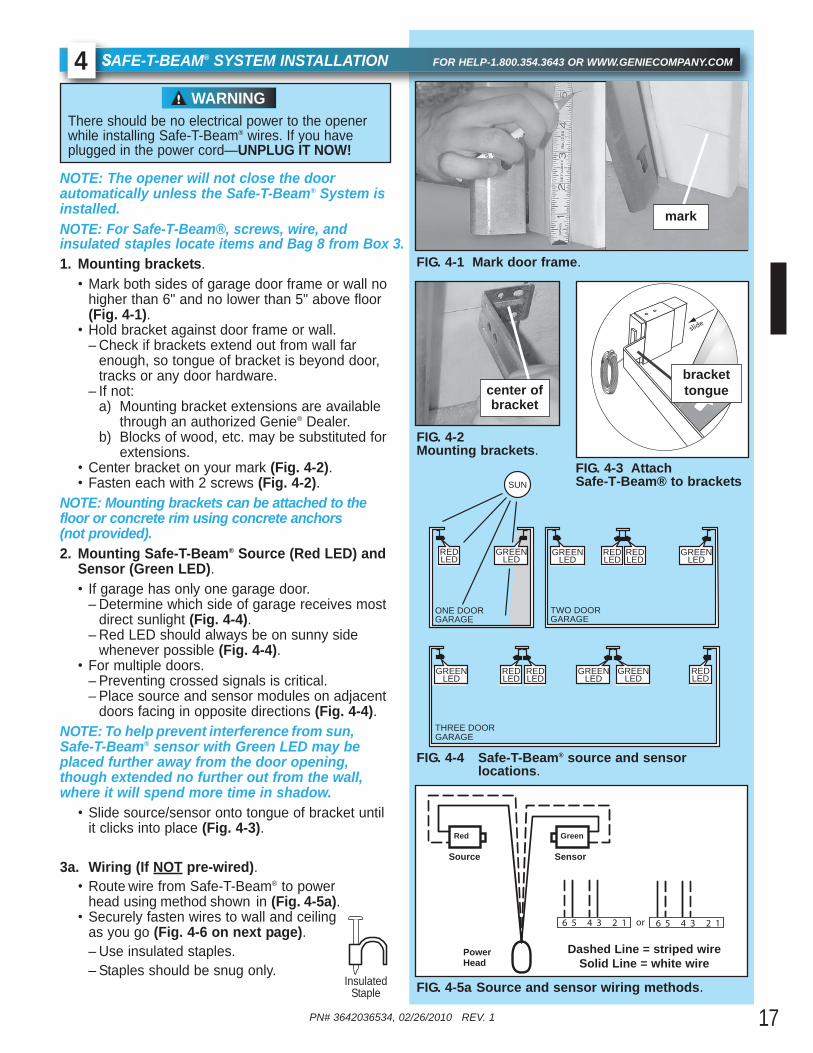
NOTE: The opener will not close the door automatically unless the Safe-T-Beam® System isinstalled.NOTE: For Safe-T-Beam®, screws, wire, and insulated staples locate items and Bag 8 from Box 3.1. Mounting brackets.
• Mark both sides of garage door frame or wall nohigher than 6" and no lower than 5" above floor (Fig. 4-1).
• Hold bracket against door frame or wall.– Check if brackets extend out from wall far
enough, so tongue of bracket is beyond door, tracks or any door hardware.
– If not:a) Mounting bracket extensions are available
through an authorized Genie® Dealer. b) Blocks of wood, etc. may be substituted for
extensions.• Center bracket on your mark (Fig. 4-2). • Fasten each with 2 screws (Fig. 4-2).
NOTE: Mounting brackets can be attached to thefloor or concrete rim using concrete anchors (not provided).2. Mounting Safe-T-Beam® Source (Red LED) and
Sensor (Green LED).• If garage has only one garage door.
– Determine which side of garage receives most direct sunlight (Fig. 4-4).
– Red LED should always be on sunny side whenever possible (Fig. 4-4).
• For multiple doors.– Preventing crossed signals is critical.– Place source and sensor modules on adjacent
doors facing in opposite directions (Fig. 4-4).NOTE: To help prevent interference from sun,Safe-T-Beam® sensor with Green LED may beplaced further away from the door opening,though extended no further out from the wall,where it will spend more time in shadow.
• Slide source/sensor onto tongue of bracket until it clicks into place (Fig. 4-3).
3a. Wiring (If NOT pre-wired). • Route wire from Safe-T-Beam® to power
head using method shown in (Fig. 4-5a).• Securely fasten wires to wall and ceiling
as you go (Fig. 4-6 on next page).– Use insulated staples.– Staples should be snug only.
There should be no electrical power to the openerwhile installing Safe-T-Beam® wires. If you haveplugged in the power cord—UNPLUG IT NOW!
WARNING
FIG. 4-1 Mark door frame.
FIG. 4-2 Mounting brackets.
FIG. 4-3 Attach Safe-T-Beam® to brackets.
slide
brackettongue
mark
center ofbracket
FIG. 4-4 Safe-T-Beam® source and sensor locations.
SUN
ONE DOORGARAGE
THREE DOORGARAGE
REDLED
REDLED
GREENLED
REDLED
GREENLED
GREENLED
GREENLED
REDLED
REDLED
REDLED
GREENLED
GREENLED
TWO DOORGARAGE
FIG. 4-5a Source and sensor wiring methods.
or6 5 4 3 2 1 6 5 4 3 2 1
SensorSource
neerGdeR
PowerHead
Dashed Line = striped wireSolid Line = white wire
InsulatedStaple

PN# 3642036534, 02/26/2010 REV. 118
3b. Wiring (pre-wired). • Route wire from wall to Safe-T-Beam® sensors
(Fig. 4-5b).• Splice pre-wiring to shortened sensor wire,
match wire pairs dash-to-dash and plain-to-plain. - Trim sensor wire to approximately one foot
(1 ft) from sensor. - Split and strip ends of sensor wires and
pre-wired wires (Fig. 4-7).- Splice wires together with (provided)
wire nuts. • Route wire from ceiling to power head
(Fig. 4-5b).• Securely fasten wires where they exit
wall and ceiling as you go.– Use insulated staples.– Staples should be snug only.
4. Split and strip ends of sensor wires (Fig. 4-7).
NOTE: For rear cover locate Box 4.5. Attach Safe-T-Beam® wire to power head wire
terminal.• Route Safe-T-Beam® wires through wire guide.
– Insert wire into terminal holes and lightly press in the orange locking clips above each terminalhole. (You can use a pencil or small screwdriver to comfortably reach in and lightly press down locking clips.) Insert white wires to 'even' numbered terminal holes and striped wires into 'odd' terminal holes (Fig. 4-5b).
– Confirm wire lock by lightly tugging on the wire. The wire should remain in the terminal hole.
• Install rear cover. The rear cover is the same color as the power head clips and body (Fig. 4-9).
• Do not install the white (lamp) cover at this time. NOTE: Safe-T-Beam® alignment check must be performed following connection to electricalpower (see page 19). DO NOT PLUG IN YET!
Staples which are too tight can cut or pinch wires.Cut or pinched wires can cause the Safe-T-Beam®
System to stop working. When using the insulatedstaples, make sure you fasten them only as tightlyas needed to hold the wire snugly.
CAUTION
FIG. 4-7Splitting and stripping
.
FIG. 4-6 Wire routing.
Wire
Wire
Source or Sensor
Invisible Light BeamProtection Area
Insert Wire Into Connector
Use this wire routing
if NOT pre-wired
1234
Terminal Holes
Locking Clips
56
+ –P B
Infrared Sensor
123456
FIG. 4-8Insert wires
.
(Power Head With Rear Cover Removed)
FIG. 4-5b Pre-Wired source and sensor wiring methods.
or6 5 4 3 2 1 6 5 4 3 2 1
SensorSource
neerGdeR
PowerHead
Dashed Line = striped wireSolid Line = white wire
Dashed Line = striped wire
Solid Line = white wire
Wall Wall
Ceiling
1/2"2"
Cover clipsFIG. 4-9 Install rear cover.
InsulatedStaple
Wire Nut
Source or Sensor
PN# 3642036534, 02/26/2010 REV. 1 19
ONNECTING TO POWER FOR HELP-1.800.354.3643 OR WWW.GENIECOMPANY.COM5
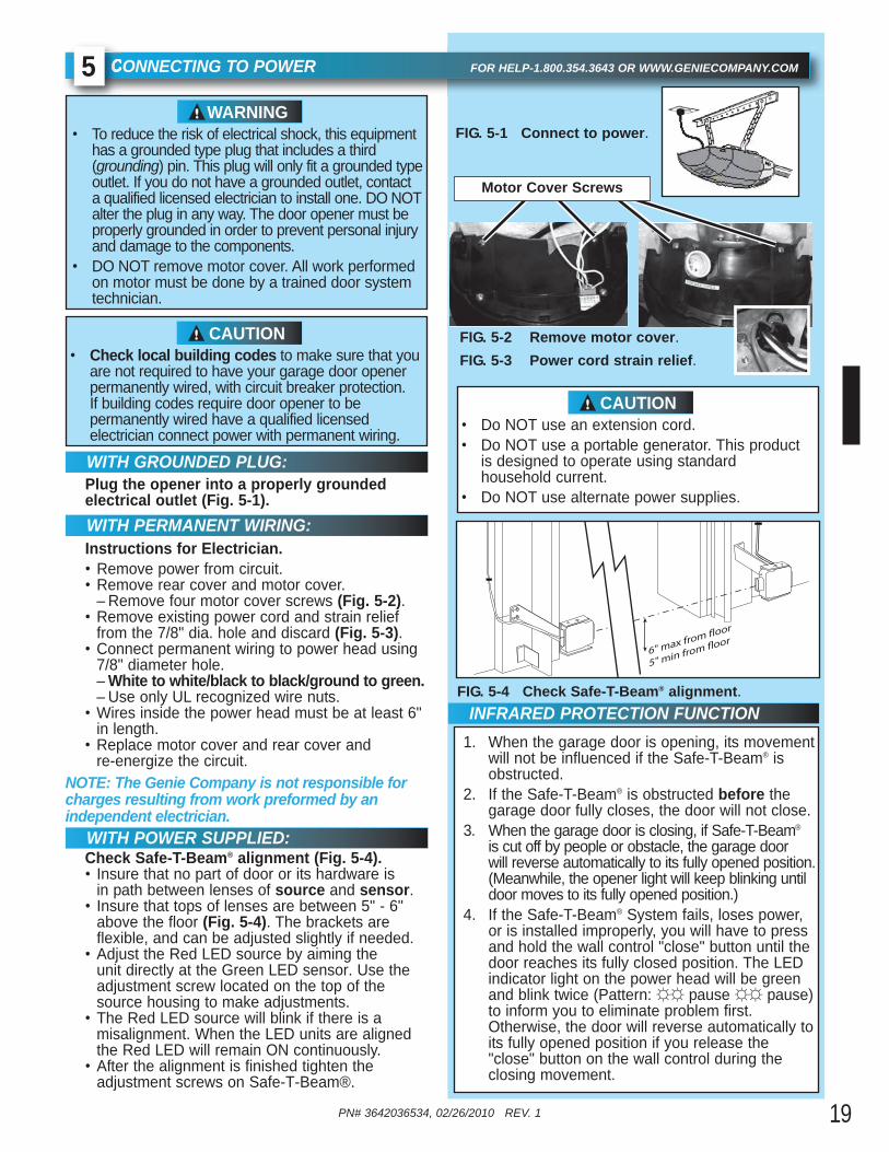
Plug the opener into a properly grounded electrical outlet (Fig. 5-1).
• To reduce the risk of electrical shock, this equipment has a grounded type plug that includes a third (grounding) pin. This plug will only fit a grounded typeoutlet. If you do not have a grounded outlet, contact a qualified licensed electrician to install one. DO NOTalter the plug in any way. The door opener must be properly grounded in order to prevent personal injury and damage to the components.
• DO NOT remove motor cover. All work performed on motor must be done by a trained door system technician.
WARNING
• Check local building codes to make sure that youare not required to have your garage door opener permanently wired, with circuit breaker protection. If building codes require door opener to be permanently wired have a qualified licensed electrician connect power with permanent wiring.
CAUTION
WITH GROUNDED PLUG:
5" min from floor6" max from floor
FIG. 5-4 Check Safe-T-Beam® alignment.
FIG. 5-1 Connect to power.
INFRARED PROTECTION FUNCTION1. When the garage door is opening, its movement
will not be influenced if the Safe-T-Beam® is obstructed.
2. If the Safe-T-Beam® is obstructed before the garage door fully closes, the door will not close.
3. When the garage door is closing, if Safe-T-Beam®
is cut off by people or obstacle, the garage door will reverse automatically to its fully opened position.(Meanwhile, the opener light will keep blinking until door moves to its fully opened position.)
4. If the Safe-T-Beam® System fails, loses power, or is installed improperly, you will have to press and hold the wall control "close" button until the door reaches its fully closed position. The LEDindicator light on the power head will be green and blink twice (Pattern: ☼☼ pause ☼☼ pause)to inform you to eliminate problem first. Otherwise, the door will reverse automatically toits fully opened position if you release the "close" button on the wall control during the closing movement.
FIG. 5-2 Remove motor cover.
WITH PERMANENT WIRING:Instructions for Electrician.• Remove power from circuit. • Remove rear cover and motor cover.
– Remove four motor cover screws (Fig. 5-2).• Remove existing power cord and strain relief
from the 7/8" dia. hole and discard (Fig. 5-3).• Connect permanent wiring to power head using
7/8" diameter hole. – White to white/black to black/ground to green.– Use only UL recognized wire nuts.
• Wires inside the power head must be at least 6" in length.
• Replace motor cover and rear cover and re-energize the circuit.
NOTE: The Genie Company is not responsible forcharges resulting from work preformed by an independent electrician.
Check Safe-T-Beam® alignment (Fig. 5-4).• Insure that no part of door or its hardware is
in path between lenses of source and sensor. • Insure that tops of lenses are between 5" - 6"
above the floor (Fig. 5-4). The brackets are flexible, and can be adjusted slightly if needed.
• Adjust the Red LED source by aiming the unit directly at the Green LED sensor. Use the adjustment screw located on the top of the source housing to make adjustments.
• The Red LED source will blink if there is a misalignment. When the LED units are aligned the Red LED will remain ON continuously.
• After the alignment is finished tighten the adjustment screws on Safe-T-Beam®.
Motor Cover Screws
FIG. 5-3 Power cord strain relief.
• Do NOT use an extension cord. • Do NOT use a portable generator. This product
is designed to operate using standard household current.
• Do NOT use alternate power supplies.
CAUTION
WITH POWER SUPPLIED:

PN# 3642036534, 02/26/2010 REV. 120
OOR LIMITS FOR HELP-1.800.354.3643 OR WWW.GENIECOMPANY.COM6
The OPEN (UP) and CLOSE (DOWN) door positionsare controlled by making the adjustments on thepanel located on the bottom of the power head. Theadjustments that can be made are:
• Close Travel Limit, • Open Travel Limit,
Maximum Closing Force Maximum Opening ForceTransmitter Programming
SETTING & TESTING OPEN/CLOSE LIMITS
FIG. 6-1 Limit controls.
SET
SET
OPEN
FORCE
CLOSECODE
LEARN LIMITMANUAL
Open Travel Limit
Open Set LimitButton
Close Travel Limit
Close Set LimitButton
Down ForceControl
Adjustment
Up ForceControl
Adjustment
Learn Code
Button
LEDIndicator Light
To Garage Door
• Severe injury or death can result if the door closing force is set too high.
• Never increase the door closing force above the minimum required to move the door.
• Never adjust force to compensate for a sticking or binding door.
• Perform monthly CONTACT REVERSE TEST as described on page 22 and in Section 10.
WARNINGLimit Controls locationon power head.
CLOSE TRAVEL LIMIT1. Press and hold the "Close Travel Limit" button
until the door is fully closed. 2. You can quickly press and release the "Close
Travel Limit" button to move the door in small increments. You can also use the "Open Travel Limit" button to move the door slightly in the UP direction.
3. Door is fully closed when the bottom edge of door presses firmly onto the ground.
4. Once the door is in the desired position, press andrelease the "Close SET Limit" button for 5 seconds. The LED indicator light will blink green once. This stores the closed position in memory.
OPEN TRAVEL LIMIT1. Press and hold the "Open Travel Limit" button
to move the door to its fully opened position. This starts the opener moving in the UP direction.
2. Hold the "Open Travel Limit" button until the door is in the fully opened position that you desire, then release this button.
3. You can quickly press and release the "Open Travel Limit" button to move the door in small increments. You can also use the "Close Travel Limit" button to move the door slightly in the DOWN direction.
4. Once the door is in the desired position, press and release the "Open SET Limit" button for 5 seconds. The LED indicator light will blink green twice. This stores the opened position in memory.
SET
SET
Carriage Assembly
Chain Connector
Latch Movement
Latch Movement
Move in this direction
Carriage Assembly
Belt Connector
Latch Movement
Latch Movement
Move in this direction
FIG. 6-2 Engage Chain/Belt Connector to Carriage.
Operation of the opener without the Chain or BeltConnector engaged to the Carriage Assembly willresult in damage to rail components including therail pulley.
CAUTION
ENGAGE CHAIN/BELT CONNECTOR TOCARRIAGE1. Press and hold the "Close Travel Limit" button
until the chain or belt connector advances and engages to the Carriage Assembly (FIG 6-2).
Failure to verify the engagement of the belt/chainconnector will result in damage to rail components.
CAUTION
NOTE: Set Close Travel Limitbefore setting Open TravelLimit for unit to operate normally.Unless limits are being resetdo not press set limit buttons.
21
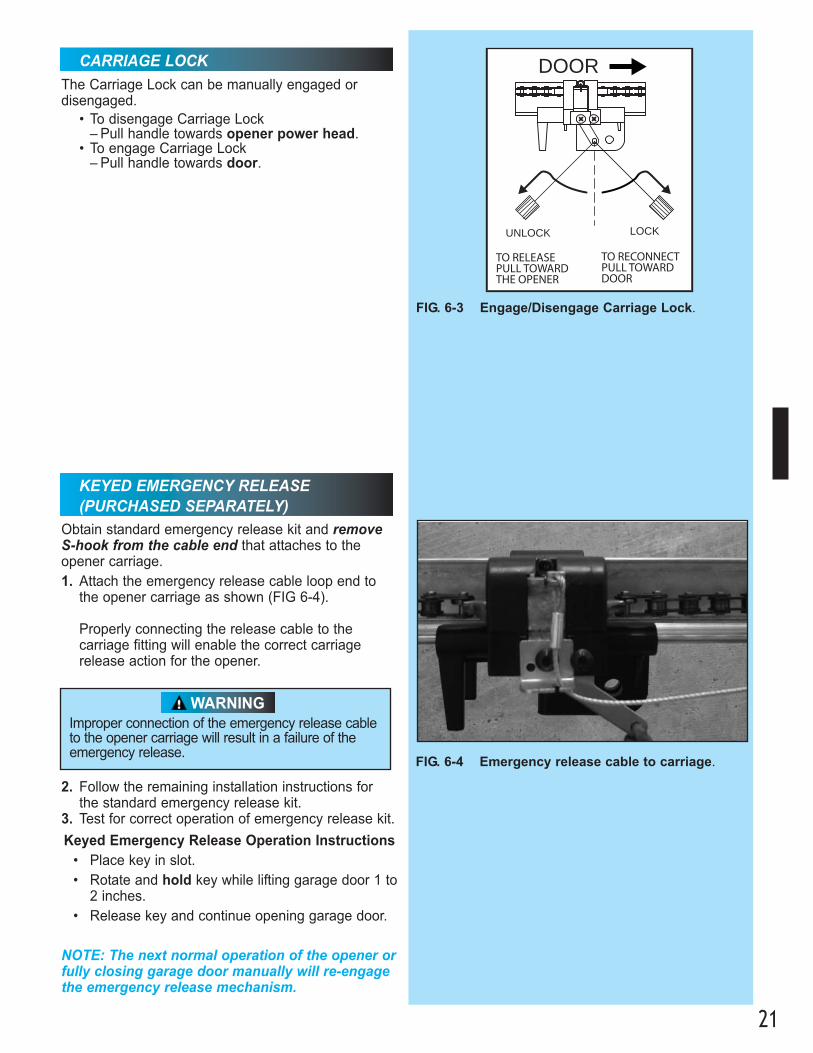
Obtain standard emergency release kit and removeS-hook from the cable end that attaches to the opener carriage.1. Attach the emergency release cable loop end to
the opener carriage as shown (FIG 6-4).
Properly connecting the release cable to the carriage fitting will enable the correct carriage release action for the opener.
FIG. 6-4 Emergency release cable to carriage.
UNLOCK
DOOR
LOCK
TO RECONNECT PULL TOWARD DOOR
TO RELEASE PULL TOWARD THE OPENER
FIG. 6-3 Engage/Disengage Carriage Lock.
CARRIAGE LOCKThe Carriage Lock can be manually engaged or disengaged.
• To disengage Carriage Lock – Pull handle towards opener power head.
• To engage Carriage Lock – Pull handle towards door.
Improper connection of the emergency release cableto the opener carriage will result in a failure of theemergency release.
WARNING
2. Follow the remaining installation instructions for the standard emergency release kit.
3. Test for correct operation of emergency release kit.
Keyed Emergency Release Operation Instructions• Place key in slot.• Rotate and hold key while lifting garage door 1 to
2 inches.• Release key and continue opening garage door.
NOTE: The next normal operation of the opener orfully closing garage door manually will re-engagethe emergency release mechanism.
KEYED EMERGENCY RELEASE(PURCHASED SEPARATELY)
PN# 3642036534, 02/26/2010 REV. 122
FIG. 6-6 2 x 4 under center of door opening.
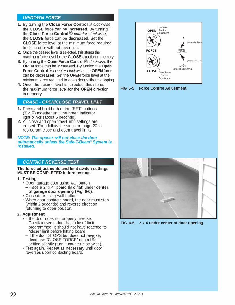
CONTACT REVERSE TESTThe force adjustments and limit switch settingsMUST BE COMPLETED before testing.1. Testing.
• Open garage door using wall button.– Place a 2" x 4" board (laid flat) under center
of garage door opening (Fig. 6-6). • Close door using wall button.• When door contacts board, the door must stop
(within 2 seconds) and reverse direction returning to open position.
2. Adjustment.• If the door does not properly reverse.
– Check to see if door has "close" limit programmed. It should not have reached its "close" limit before hitting board.
– If the door STOPS but does not reverse, decrease "CLOSE FORCE" control setting slightly (turn it counter-clockwise).
• Test again. Repeat as necessary until door reverses upon contacting board.
CLOSE
1. Press and hold both of the "SET" buttons ( & ) together until the green indicator light blinks (about 5 seconds).
2. All close and open travel limit settings are erased. Then follow the steps on page 20 to reprogram close and open travel limits.
NOTE: The opener will not close the door automatically unless the Safe-T-Beam® System isinstalled.
SETSET
1. By turning the Close Force Control clockwise, the CLOSE force can be increased. By turning the Close Force Control counter-clockwise, the CLOSE force can be decreased. Set the CLOSE force level at the minimum force required to close door without reversing.
2. Once the desired level is selected, this stores the maximum force level for the CLOSE direction in memory.
3. By turning the Open Force Control clockwise, the OPEN force can be increased. By turning the OpenForce Control counter-clockwise, the OPEN force can be decreased. Set the OPEN force level at the minimum force required to open door without stopping.
4. Once the desired level is selected, this stores the maximum force level for the OPEN direction in memory.
OPEN
CLOSE
OPEN
CLOSE
UP/DOWN FORCE
ERASE - OPEN/CLOSE TRAVEL LIMIT
OPEN
FORCE
CLOSE Down ForceControl
Adjustment
Up ForceControl
Adjustment
ROTATECLOCKWISE
ROTATECOUNTER-CLOCKWISE
(Increasing Force
(Decreasing Force
FIG. 6-5 Force Control Adjustment.

PN# 3642036534, 02/26/2010 REV. 1 23
FCC and IC CERTIFIED
FIG. 7-1 Learn code button and LED
SET
SET
OPEN
FORCE
CLOSECODE
LEARN LIMITMANUAL
Open Travel Limit
Open Set LimitButton
Close Travel Limit
Close Set LimitButton
Down ForceControl
Adjustment
Up ForceControl
Adjustment
Learn Code
Button
LEDIndicator Light
To Garage Door
This device complies with FCC Part 15 and RSS 210of Industry Canada. This equipment has been testedand found to comply with the limits for a Class B digital device, pursuant to Part 15 of the FCC Rules.These limits are designed to provide reasonable protection against harmful interference in a residentialinstallation. This equipment generates, uses and canradiate radio frequency energy and, if not installedand used in accordance with the instructions, maycause harmful interference to radio communications.However, there is no guarantee that interference willnot occur in a particular installation. If this equipmentdoes cause harmful interference to radio or televisionreception, which may be determined by turning theequipment OFF and ON, the user is encouraged totry to correct the interference by one or more of thefollowing measures:• Re-orient or relocate the receiver antenna.• Increase the separation between the opener
and receiver.• Connect the opener into an outlet on a circuit
different from that to which the receiver is connected.
• Consult your local dealer.
ROGRAMMING REMOTE CONTROLS7
NOTE: For remote control locate Box 3.1a. Single Button Remote Programming.NOTE: This opener can learn up to 7 transmitterbuttons.
• Locate “Learn Code” button and indicator LED on the power head (Fig. 7-1).
• Press and release “Learn Code” button.– Indicator LED will blink RED at a rate of twice
per second.• Within 30 seconds, push remote control
button once.– Indicator LED will stop blinking and stay ON.
• Press remote control button again.
• Press remote control button again, door will move.
– Red LED will go out. Remote is now programmed and ready for use.
1b. Multi Button Remote Programming.NOTE: Each button on a multi-button remote is designed for use with 1 door. You cannot program 2 buttons to operate the same door, norcan you program 1 button to operate 2 doors.You can program a maximum of 7 different transmitters or wireless devices.NOTE: Pushing two buttons on power head simultaneously will erase programmed memory andlimits must be reset.
• For each button.– Program each button separately using the
Single Button Remote Programming steps.2. Operating.
• Press remote button once.– Door will move.
• Press button again.– Door will stop.
• Press button again. – Door will move in opposite direction.
NOTE: The door will stop automatically at thefully open or fully closed position.
CODE
LEARN
A moving door can cause serious injury or death.1. Keep people clear of opening while door is
moving.2. Do NOT allow children to play with opener,
including wall button, remote control, or Wireless Keypad.
3. During programming, the door opener could begin to run, so keep people and objects away from the moving door and its parts. To keep thedoor from moving, close the door and disconnect it from the Opener by pulling the Emergency Release.
WARNING
LOST OR STOLEN REMOTE1. Clear memory.
• Press and hold learn code button (on power head) for 10 seconds or until the red blinking indicator LED goes out.
• Program remaining or new remote controls as done previously. Your door opener will no longer recognize any signal received from the missing remote control, or any other which has not been reprogrammed.
NOTE: To program aHomelink® and Car2U®
device follow the Homelink® or Car2U®
instructions in your car owner’s manual.
Limit controls locationon power head.

EMOTE CONTROL BATTERY REPLACEMENT AND VISOR CLIP INSTALLATION8
FIG. 8-1 Open battery cover.
1. Battery replacement.• To open gently push straight out on battery
cover lock tab as shown (Fig. 8-1).• Flip open battery cover.
– Remove old battery.• Make sure new battery is facing proper direction
(Match battery polarity with symbols inside battery cover) (Fig. 8-2).– Recommended replacement battery type:
Alkaline A23, 12 volt.
NOTE: Batteries differ in care and maintenance.Follow the manufacturer’s directions for batterymaintenance, replacement, and use.
• Slip new battery into place.– Slide battery cover until it clicks shut.
• Operate remote to make sure it is working properly. (No re-programming is needed.)
2. Visor clip.(The visor clip may come already installed.)You will have to install the visor clip if you choose to attach your remote to the car visor.• Slide visor clip into back of remote control.
– It will snap into place (Fig. 8-3).
FIG. 8-3 Attach visor clip.
FIG. 8-2 Match battery polarity.
LIGHT BULB/LENS INSTALLATION9
FIG. 9-2 Fasten lens.
NOTE: For lens cover locate Box 4.
1. Light bulb. • Recommendations.
– Do NOT use a short neck bulb.– Light bulb should be no more than 75 Watts.– Use a heavy duty service bulb for longer life.
• Screw bulb into socket.2. Lens.
• Select the white (lamp) cover. Do NOT use the colored cover in this location.
• Line up lamp lens tabs on power head with corresponding slots in lens (Fig. 9-1).
• Slide lens onto power head. Make sure the tabs are fully engaged into lens slots (Fig. 9-2).
• Plug power cord back into electrical outlet.
– and + polarity marks
FIG. 9-1 Slide lens onto motor cover.
Lens tabs
Light bulb
Slide out
PN# 3642036534, 02/26/2010 REV. 124
For added safety and protection please unplug opener before installing light bulb.
WARNING

PN# 3642036534, 02/26/2010 REV. 1 25
Use wall button supplied with opener. Any other wall control can causethe opener to operate unexpectedly.
WARNING
If you have any questions, please do not hesitate to contact Genie® customer service at:1.800.354.3643
IMPORTANT SAFETY INSTRUCTIONS
1. READ AND FOLLOW ALL INSTRUCTIONS.
2. Never let children operate or play with the door controls. Keep the remote control away from children.
3. Always keep the moving door in sight and away from people and objects until the door is completelyclosed. NO ONE SHOULD CROSS THE PATH OF THE MOVING DOOR.
4. NEVER GO UNDER A STOPPED, PARTIALLY OPEN DOOR.
5. Test opener monthly. The door MUST reverse on contact with a 1-1/2" high object (or a 2" x 4" boardlaid flat) at the center of the doorway on the floor. After adjusting either the force or the limit of travel,retest the door opener. Failure to adjust the opener properly may cause severe injury or death.
6. When possible, use the emergency release only when the door is closed. Use caution when using thisrelease with the door open. Weak or broken springs are capable of increasing the rate of door closureand increasing the risk of severe injury or death.
7. KEEP DOORS PROPERLY BALANCED. See your garage door Owner’s Manual. An improperly balanced door increases the risk of severe injury or death. Have a trained door system technician makerepairs to cables, spring assemblies, and other hardware.
8. SAVE THESE INSTRUCTIONS.
WARNING:To reduce the risk of severe injury or death:
MAINTENANCE
1. Door balance.• With the door closed, pull emergency release
knob (Carriage Lock) towards the opener to release door from carriage assembly.
• Raise door manually approximately 3'- 4' and release. – Door should remain stationary or move very
slightly. – If door moves quickly, CONTACT A TRAINED
DOOR SYSTEM TECHNICIAN.• Close the door.• Pull emergency release knob towards door to
engage carriage. – Operate door using remote.– Door will re-attach itself to carriage assembly.
ROUTINE MONTHLY MAINTENANCE
2. Contact reverse.• Place a 2" x 4" board laid flat on floor.
– In center of garage door opening.• Close door by using wall button or
remote control.– Door fails to reverse on contact with board
(See section "CONTACT REVERSE.")– Opener still fails
CONTACT THE GENIE COMPANY OR AN AUTHORIZED GENIE® DEALER.
3. Safe-T-Beam® System.• Red LED blinks.
– check alignment (See section ).
7
5
10
• Garage door hardware (springs, cables, brackets, pulleys, etc.) are under extreme pressure and tension.
• DO NOT attempt to repair or adjust door springs or any hardware, and DO NOT OPERATE garage door automatically or manually if door is improperly balanced or springs are broken. – CONTACT A TRAINED DOOR SYSTEM
TECHNICIAN.
WARNING
PN# 3642036534, 02/26/2010 REV. 126
CIRCUIT WIRING DIAGRAM FOR HELP-1.800.354.3643 OR WWW.GENIECOMPANY.COM
123456
1 2 3 41 2 31 2
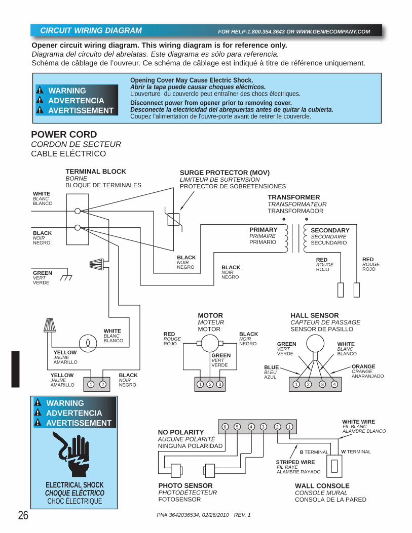
POWER CORDCORDON DE SECTEURCABLE ELÉCTRICO
TERMINAL BLOCKBORNEBLOQUE DE TERMINALES
WHITEBLANCBLANCO
BLACKNOIRNEGRO
GREENVERTVERDE
SURGE PROTECTOR (MOV)LIMITEUR DE SURTENSIONPROTECTOR DE SOBRETENSIONES
TRANSFORMERTRANSFORMATEURTRANSFORMADOR
PRIMARYPRIMAIREPRIMARIO
BLACKNOIRNEGRO BLACK
NOIRNEGRO
YELLOWJAUNEAMARILLO
WHITEBLANCBLANCO
BLACKNOIRNEGRO
REDROUGEROJO
BLACKNOIRNEGRO
HALL SENSORCAPTEUR DE PASSAGESENSOR DE PASILLO
STRIPED WIREFIL RAYÉALAMBRE RAYADO
WALL CONSOLECONSOLE MURALCONSOLA DE LA PARED
YELLOWJAUNEAMARILLO
MOTORMOTEURMOTOR
GREENVERTVERDE
REDROUGEROJO
REDROUGEROJO
GREENVERTVERDE
WHITEBLANCBLANCO
BLUEBLEUAZUL
ORANGEORANGEANARANJADO
WHITE WIREFIL BLANC ALAMBRE BLANCO
W TERMINALB TERMINAL
PHOTO SENSORPHOTODÉTECTEURFOTOSENSOR
NO POLARITYAUCUNE POLARITÉNINGUNA POLARIDAD
SECONDARYSECONDAIRESECUNDARIO
Opener circuit wiring diagram. This wiring diagram is for reference only.Diagrama del circuito del abrelatas. Este diagrama es sólo para referencia.Schéma de câblage de l’ouvreur. Ce schéma de câblage est indiqué à titre de référence uniquement.
Opening Cover May Cause Electric Shock. Abrir la tapa puede causar choques eléctricos.L’ouverture du couvercle peut entraîner des chocs électriques.Disconnect power from opener prior to removing cover.Desconecte la electricidad del abrepuertas antes de quitar la cubierta.Coupez l'alimentation de l'ouvre-porte avant de retirer le couvercle.
WARNINGADVERTENCIAAVERTISSEMENT
ELECTRICAL SHOCKCHOQUE ELÉCTRICOCHOC ÉLECTRIQUE
WARNINGADVERTENCIAAVERTISSEMENT
PN# 3642036534, 02/26/2010 REV. 1 27
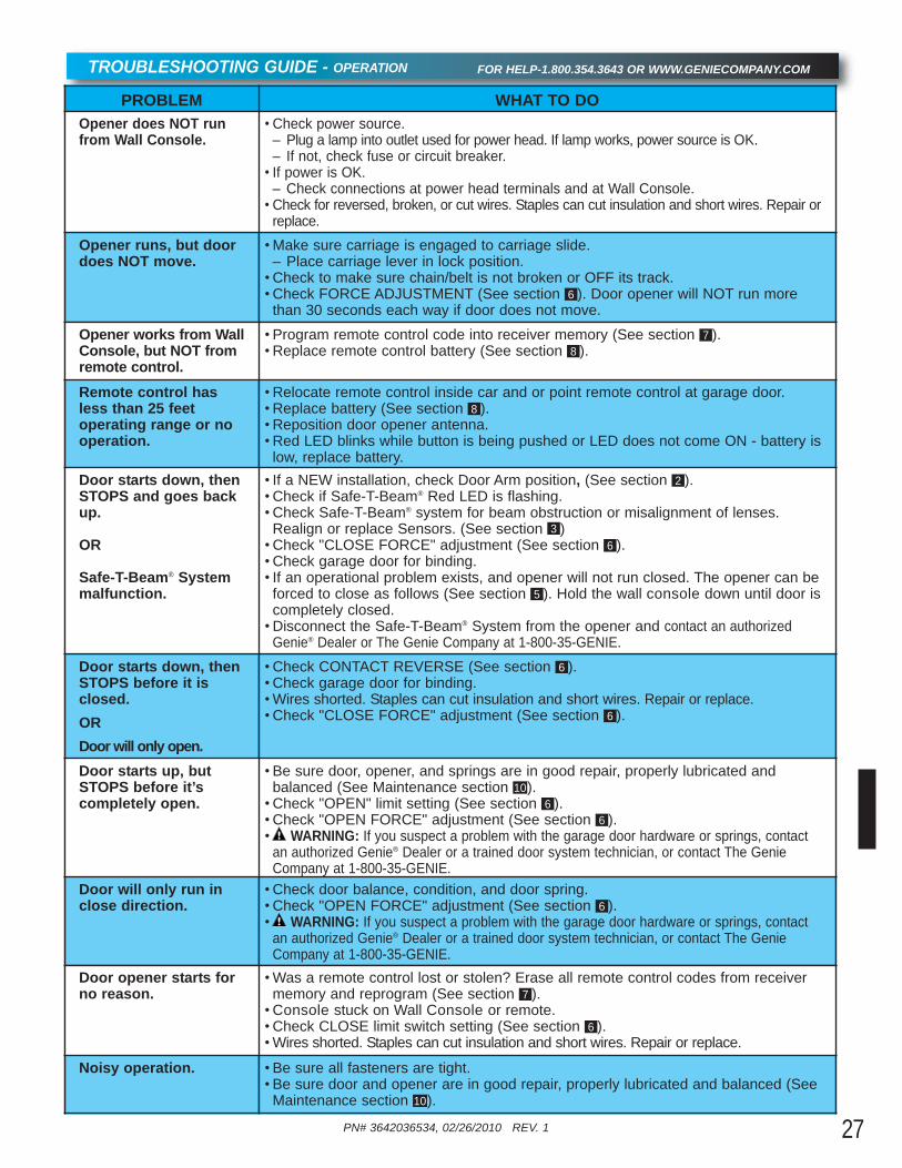
TROUBLESHOOTING GUIDE - OPERATION FOR HELP-1.800.354.3643 OR WWW.GENIECOMPANY.COM
PROBLEM WHAT TO DOOpener does NOT runfrom Wall Console.
• Check power source.– Plug a lamp into outlet used for power head. If lamp works, power source is OK.– If not, check fuse or circuit breaker.• If power is OK.
– Check connections at power head terminals and at Wall Console. • Check for reversed, broken, or cut wires. Staples can cut insulation and short wires. Repair or
replace.Opener runs, but doordoes NOT move.
•Make sure carriage is engaged to carriage slide.– Place carriage lever in lock position.•Check to make sure chain/belt is not broken or OFF its track.•Check FORCE ADJUSTMENT (See section ). Door opener will NOT run morethan 30 seconds each way if door does not move.
6
Opener works from WallConsole, but NOT fromremote control.
•Program remote control code into receiver memory (See section ).•Replace remote control battery (See section ).8
7
Remote control hasless than 25 feet operating range or nooperation.
•Relocate remote control inside car and or point remote control at garage door.•Replace battery (See section ).•Reposition door opener antenna.•Red LED blinks while button is being pushed or LED does not come ON - battery islow, replace battery.
8
Door starts down, thenSTOPS and goes backup.
OR
Safe-T-Beam® Systemmalfunction.
• If a NEW installation, check Door Arm position, (See section ).•Check if Safe-T-Beam® Red LED is flashing.•Check Safe-T-Beam® system for beam obstruction or misalignment of lenses.Realign or replace Sensors. (See section )•Check "CLOSE FORCE" adjustment (See section ).•Check garage door for binding.• If an operational problem exists, and opener will not run closed. The opener can beforced to close as follows (See section ). Hold the wall console down until door iscompletely closed. •Disconnect the Safe-T-Beam® System from the opener and contact an authorized
Genie® Dealer or The Genie Company at 1-800-35-GENIE.
5
63
2
Door starts down, thenSTOPS before it isclosed.ORDoor will only open.
•Check CONTACT REVERSE (See section ).•Check garage door for binding.•Wires shorted. Staples can cut insulation and short wires. Repair or replace.•Check "CLOSE FORCE" adjustment (See section ).6
6
Door starts up, butSTOPS before it’s completely open.
•Be sure door, opener, and springs are in good repair, properly lubricated and balanced (See Maintenance section ).•Check "OPEN" limit setting (See section ).•Check "OPEN FORCE" adjustment (See section ).• WARNING: If you suspect a problem with the garage door hardware or springs, contact
an authorized Genie® Dealer or a trained door system technician, or contact The GenieCompany at 1-800-35-GENIE.
10
66
Door will only run inclose direction.
•Check door balance, condition, and door spring.•Check "OPEN FORCE" adjustment (See section ).• WARNING: If you suspect a problem with the garage door hardware or springs, contact
an authorized Genie® Dealer or a trained door system technician, or contact The GenieCompany at 1-800-35-GENIE.
6
Door opener starts forno reason.
•Was a remote control lost or stolen? Erase all remote control codes from receivermemory and reprogram (See section ).•Console stuck on Wall Console or remote.•Check CLOSE limit switch setting (See section ).•Wires shorted. Staples can cut insulation and short wires. Repair or replace.
6
7
Noisy operation. •Be sure all fasteners are tight.•Be sure door and opener are in good repair, properly lubricated and balanced (SeeMaintenance section ).10
PN# 3642036534, 02/26/2010 REV. 1
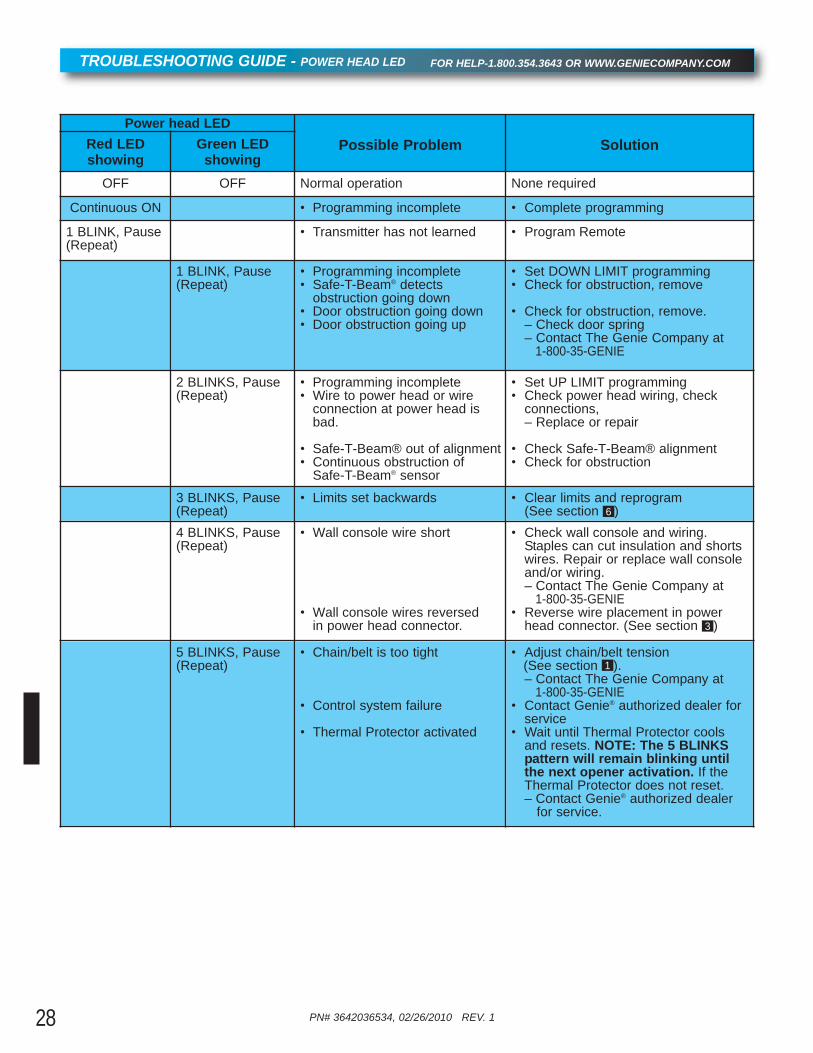
TROUBLESHOOTING GUIDE - POWER HEAD LED FOR HELP-1.800.354.3643 OR WWW.GENIECOMPANY.COM
Power head LEDPossible Problem SolutionRed LED
showingGreen LED
showingOFF OFF Normal operation None required
Continuous ON • Programming incomplete • Complete programming
1 BLINK, Pause(Repeat)
• Transmitter has not learned • Program Remote
1 BLINK, Pause(Repeat)
• Programming incomplete• Safe-T-Beam® detects
obstruction going down• Door obstruction going down• Door obstruction going up
• Set DOWN LIMIT programming• Check for obstruction, remove
• Check for obstruction, remove. – Check door spring – Contact The Genie Company at
1-800-35-GENIE
2 BLINKS, Pause(Repeat)
• Programming incomplete• Wire to power head or wire
connection at power head is bad.
• Safe-T-Beam® out of alignment• Continuous obstruction of
Safe-T-Beam® sensor
• Set UP LIMIT programming• Check power head wiring, check
connections, – Replace or repair
• Check Safe-T-Beam® alignment• Check for obstruction
3 BLINKS, Pause(Repeat)
• Limits set backwards • Clear limits and reprogram (See section )6
4 BLINKS, Pause(Repeat)
• Wall console wire short
• Wall console wires reversed in power head connector.
• Check wall console and wiring. Staples can cut insulation and shorts wires. Repair or replace wall console and/or wiring. – Contact The Genie Company at
1-800-35-GENIE• Reverse wire placement in power
head connector. (See section )3
5 BLINKS, Pause(Repeat)
• Chain/belt is too tight
• Control system failure
• Thermal Protector activated
• Adjust chain/belt tension (See section ).– Contact The Genie Company at
1-800-35-GENIE• Contact Genie® authorized dealer for
service• Wait until Thermal Protector cools
and resets. NOTE: The 5 BLINKS pattern will remain blinking until the next opener activation. If the Thermal Protector does not reset.– Contact Genie® authorized dealer
for service.
1
28
PN# 3642036534, 02/26/2010 REV. 1 29
Transmitters comply with all United States and Canadian legal requirements as of the date of manufacture. No warranty is madethat they comply with all legal requirements of any other jurisdiction. If transmitters are to be used in another country, the importermust determine compliance with any local laws and regulations which may differ from United States and Canadian requirementsprior to use.
Los transmisores cumplen con todas las reglamentaciones legales de los Estados Unidos y del Canadá, en la fecha de fabricación.Ninguna garantía se da que cumplan con todas las reglamentaciones legales de ninguna otra jurisdicción. Si los transmisores sevan a utilizar en otro país, el importador debe determinar si cumplen con las reglamentaciones y leyes locales que puedan serdiferentes a las reglamentaciones de los Estados Unidos y del Canadá, antes de usar los mismos.
Les émetteurs sont conformes à la réglementation américaine et canadienne à compter de leur date de fabrication. Aucune garantien’est stipulée indiquant qu’ils sont conformes à toutes les prescriptions juridiques d’autres autorités. Si les émetteurs sont utilisésdans d’autres pays, il incombe à l’importateur d’en déterminer leur conformité aux lois et règles locales pouvant différer de cellesdes États Unis et du Canada avant toute utilisation desdits émetteurs.
Sendegeräte entsprechen allen gesetzlichen Bestimmungen in den USA und Kanada zum Zeitpunkt der Herstellung. Wirübernehmen keine Gewährleistung für die Einhaltung aller gesetzlichen Bestimmungen in anderen Ländern. Sollen Sendegeräte inanderen Ländern eingesetzt werden, so muss der Importeur vor dem Gebrauch sicherstellen, dass die Sendegeräte auch solchenlokalen Bestimmungen entsprechen, welche von den Bestimmungen der USA und Kanadas abweichen.
TRANSMITTER COMPLIANCE STATEMENT

GMI Holdings, Inc d/b/a The Genie Company ("Seller") warrants to the original purchaser of the below identified opener Model 1022 or opener Model 1024 or opener Model 1042 (“Product”), subject to all of the terms and conditions hereof, that the Product and all components thereof will be free from defects in materials and workmanship for the following period(s) of time, measured from the date of purchase:
MOTOR - Seller warrants the motor for a period of FIVE (5) YEARS
PARTS - Seller warrants all other parts and components for a period of ONE (1) YEAR
Seller’s obligation under this warranty is specifically limited to repairing or replacing, at its option, the Product or any part thereof which is determined by Seller to be defective during the applicable warranty period Any labor charges are excluded and will be the responsibility of the purchaser
This warranty gives you specific legal rights, and you may also have other rights which vary from state to state This warranty is made to the original purchaser of the Product only, and is not transferable or assignable This warranty applies only to Product installed in a residential or other non-commercial application It does not cover any Product installed in commercial or industrial building applications This warranty does not apply to any unauthorized or improper installation, alteration or repair of the Product, or to any Product or component which has been damaged or deteriorated due to misuse, neglect, accident, failure to provide necessary maintenance, normal wear and tear, or acts of God or any other cause beyond the reasonable control of Seller, and does not cover batteries, missing or damaged parts from clearance or open box sales, or repairs or maintenance to door components
ALL EXPRESS AND IMPLIED WARRANTIES FOR THE PRODUCT, INCLUDING BUT NOT LIMITED TO ANY IMPLIED WARRANTIES OF MERCHANTABILITY AND FITNESS FOR A PARTICULAR PURPOSE, ARE LIMITED IN TIME TO THE APPLICABLE WARRANTY PERIOD REFLECTED ABOVE NO WARRANTIES, WHETHER EXPRESS OR IMPLIED, WILL APPLY AFTER THE LIMITED WARRANTY PERIOD HAS EXPIRED Some states do not allow limitations on how long an implied warranty lasts, so the above limitation may not apply to you
IN NO EVENT SHALL GMI HOLDINGS, INC OR OVERHEAD DOOR CORPORATION BE RESPONSIBLE FOR, OR LIABLE TO ANYONE FOR, SPECIAL, INDIRECT, COLLATERAL, PUNITIVE, INCIDENTAL OR CONSEQUENTIAL DAMAGES, even if Seller has been advised of the possibility of such damages Such excluded damages include, but are not limited to, loss of use, cost of any substitute product, or other similar indirect financial loss Some states do not allow the exclusion or limitation of incidental or consequential damages, so the above limitation or exclusion may not apply to you
Claims under this warranty must be made promptly after discovery and within the applicable warranty period To obtain warranty service, you must contact Genie® customer service and provide proof of the date and location of purchase and identification as the original purchaser Call Genie® Customer Service toll free at 1-800-354-3643 to speak with a trained representative Purchaser must allow seller a reasonable opportunity to inspect Product claimed to be defective prior to removal or alteration of its condition Upon determination by Seller that the Product or any part thereof is defective during the applicable warranty period (which may require purchaser to return the Product to Seller at purchaser’s expense), Seller will supply the purchaser with replacement parts or, at its option, a replacement Product Seller may use new or reconditioned parts, or a new or reconditioned Product of the same or similar design
There are no established informal dispute resolution procedures of the type described in the Magnuson-Moss Warranty Act
PURCHASER:
INSTALLATION ADDRESS:
DATE PURCHASED: SERIAL NUMBER:
OPENER MODEL:
REMOTE CONTROL MODEL:
DEALER NAME:
DEALER ADDRESS:
P900-775
ModelS 1022/1024/1042Limited Warranty