
Alvin Toffler‟s “Future shock” (1970) ‘Too much change in ... · Alvin Toffler‟s...
60
Transcript of Alvin Toffler‟s “Future shock” (1970) ‘Too much change in ... · Alvin Toffler‟s...


Alvin Toffler‟s “Future shock” (1970)
•1800 Discovery of infrared by Sir William Herschel
•1839 Beginnings of photography
•1850 Aerial photography using balloons
•1909 Photography from aircraft
•1972 Launch of Landsat
•1970s - 1990s: Rapid development of digital image
processing and launch of high resolution satellite
sensors
•Today ….. >125 Satellites in operation ; 90 satellites
planned for launch in next 4 years ...... CEOS Report
‘Too much change in too short a period of time’.


NASA‟s Earth Resources Technology satellite – later named
„Landsat‟ launched in 1972 was the first civil RS satellite.
“ In early 1990s the national Earth remote sensing systems were
operated by six countries (USA, China, France, India, Israel and
Japan), this number constituted 20 in 2000 and presently there
are over 30.


Current plans supplied by CEOS agencies estimate that around 90 new
satellite missions will be launched for operation between 2014 and
2018. The next few years mark a significant era for satellite Earth
observations, with more then half of these new missions to be
launched by the end of 2015.
Future Missions
China‟s FY-3 series
Korea‟s COMS series
The NOAA series of polar-orbiting satellites
EUMETSAT will launch further MetOp series
Meteosat Third Generation – Imagers & Sounders
ESA Sentinel-4 UVN mission
GCOM series (JAXA), OCO-2 (NASA) and EarthCARE (ESA/JAXA).
ADM-Aeolus (ESA) will provide new information on winds.

• AGRICULTURE & CROPS
• FOREST & BIO-RESOURCES
• WATER RESOURCES
• GEOLOGY
• OCEAN/COASTAL
• ENVIRONMENT
• RURAL DEVELOPMENT
• URBAN MANAGEMENT
• CARTOGRAPHY/MAPPING
• CLIMATE MODELLING
• GLOBAL CHANGE
INFORMATION TO SOLUTIONS

INSAT-2E
VHRR, CCD (1 KM)
INDIAN IMAGING SYSTEMS
1999
IRS-P2
LISS-2
IRS-1A & 1B
LISS-1&2 (72/36M)
BHASKARA VIDICON, SAMIR
RS-D1 SMART SENSOR
1979/81
1982
1988/91
1994
INSAT-1D
VHRR
INSAT-2A
VHRR
Geo stationary missionsPolar missions
1992
1990
IRS-1C/1D LISS-3 (23/70M,
STEERABLE PAN (5.8 M);
WiFS (188M)
IRS-P3
WiFS, MOS X-Ray
1996
1995/1997
IRS-P4 (OCEANSAT-1)
OCM, MSMR
1999
TES
STEP & STARE CONCEPT
2001
INSAT-2B
VHRR 1993
KALPANA-1
VHRR – 2 Km(vis);
8 Km(IR & WV)
2002

P band : 0.3 - 1 GHz (30 - 100 cm)
L band : 1 - 2 GHz (15 - 30 cm)
S band : 2 - 4 GHz (7.5 - 15 cm)
C band : 4 - 8 GHz (3.8 - 7.5 cm)
X band : 8 - 12.5 GHz (2.4 - 3.8 cm)
Ku band : 12.5 - 18 GHz (1.7 - 2.4 cm)
K band : 18 - 26.5 GHz (1.1 - 1.7 cm)
Ka band : 26.5 - 40 GHz (0.75 - 1.1 cm)
Pointing knowledge can sometimes be improved after the
fact, such as by monitoring the earth’s magnetic field and
later post-processing the output of a magnetometer for
better knowledge of a telescope’s pointing direction for a
particular photograph.
Pointing Stability
When given as a requirement, this is the maximum rate of
change of angular orientation allowed.
Jitter
Jitter refers to the errors in attitude of a frequency too high
to be controlled by the attitude control system. When given
as an attitude control performance requirement, it is a
specified angle bound or angular rate limit on short-term,
high-frequency motion of the spacecraft.

Pointing accuracy affects location accuracy
Angular velocities (drift rates) distorts image and affects pixel
registration
Jitter affects the resolution


Push-broom scan
• High SNR due to increased ‘dwell time’
• High geometric fidelity/accuracy
• Lower size optics – less volume, weight
• High reliability due to no moving parts and solid state technology
• Better MTF without scan mirror
Whisk-broom scan
• Less dwell time results in poorer SNR
• Scan mirror non-linearity introduce geometric errors
• Large aperture optics – more volume & weight
• Moving element - less reliable system

For
TV camera - 16 kbps
LISS - 1 - 5.2 Mbps
PAN - 105 Mbps
SAR - 360 Mbps
intT
BPbDR
Where; b is no.bits/pixel , P is no.of pixels
per band & B is no. bands Tint is
Integration time.
Payload Data Rate
sec/sec
bits
bandsbands
pixel
pixel
bits
DR
On-board storage capacity

11.375 1.375
2.75
7.33
1 1.375 1.3752.75
55
0
10
20
30
40
50
0
1
2
3
4
5
6
7
8
INSAT 1 INSAT 2 Kalpna INSAT 3D GISAT
Imp
rove
me
nt
in V
is R
es
olu
tio
n w
rt IN
SA
T 1
Imp
rove
me
nt
in IR
Re
so
luti
on
wrt
IN
SA
T 1
IR VisDoD: 1980 DoD: 1991 DoD: 2002 DoD: 2010 DoD: 2017/18
Improvement in Ground Resolution
Compared to INSAT 1 VHRR:
IR: 7.3 times
Visible: 55 times

200 200 200
300
700
0
100
200
300
400
500
600
700
800
INSAT 1 INSAT 2 Kalpna INSAT 3D GISAT
Te
les
co
pe
Dia
(mm
)
Missions
2 23
6
12+2 HyS
0
2
4
6
8
10
12
14
16
INSAT 1 INSAT 2 Kalpna INSAT 3D GISAT
Nu
mb
er
of
Ban
ds
Missions
INSAT 1 , 0.4
INSAT 2 , 0.525
Kalpna , 0.525
INSAT 3D, 4
GISAT, 200
0.1
1
10
100
0 1 2 3 4 5 6Data
Rate
(M
bp
s)
Missions

Good spatial resolution, Poor temporal resolution.

Good temporal resolution,Poor spatial resolution.

Mission…
Evolution:LEO platform Good spatial resolution,
Poor temporal resolutionGEO platform Good temporal resolution
Poor spatial resolution,That’s how GISAT was conceived with thefollowing objective…….“To tap new functionalities hitherto not coveredby existing LEO & GEO Missions like Fast revisitcapability, real time monitoring, high resolutionmulti spectral and Hyper spectral imaging - allon a single, agile, jitter free platform”

Basic applications of Payload are monitoring of Disasters, Natural hazards and calamities Episodic and Short term events etc. Spectral signatures for agriculture, forestry, mineralogy, oceanography Meteorological applications, including nowcasting
To meet these mission objectives, following baselinerequirements are contemplated:
Four Imaging channels - Multi-spectral (MX) VNIR & LWIR, Hyper spectral(HX) VNIR & SWIR
The basic telescope of CARTO-2A type with necessary modifications
The spacecraft to be agile, to enable bi-directional scanning
Electronically steerable antenna/ PAA is considered
Platform Jitter & drift rate is critical
Stringent thermal requirements

Spacecraft Mission life of 7 years, and Design life of 15 years (Radn shielding)
Launch compatibility with : (i)GSLV MK-II & (ii)Commercial launchers
Spacecraft Dry mass estimate : 1000 kg
Spacecraft Lift-off mass : 2100 kg
Deployment after T0+100sec (based on 3D flight experience)
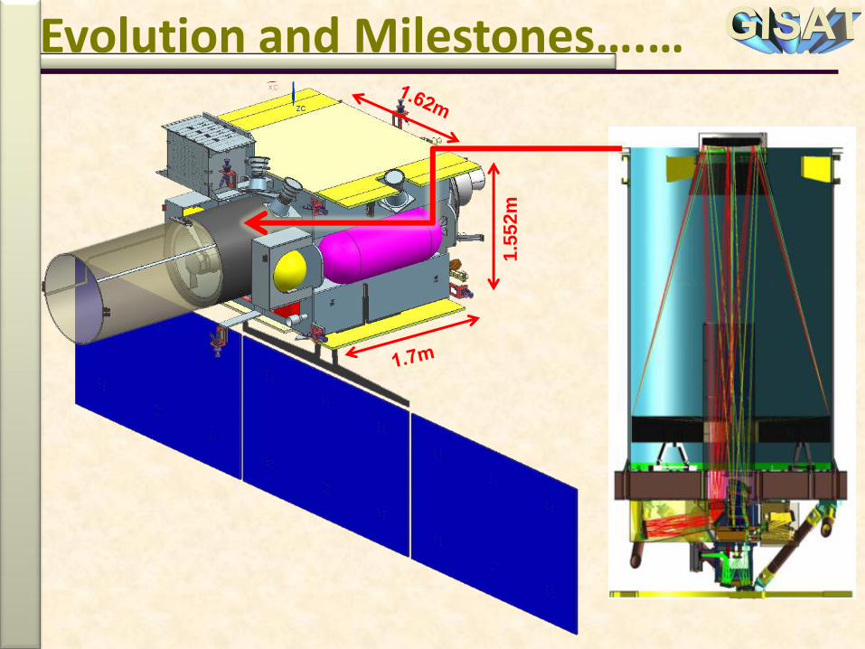
Evolution and Milestones….…
1.5
52
m

YAW
PITCH

YAW
PITCH

Thermal Heater
Cylinder
Kevlar
Hood
North Panel With E-W
dedicated Radiators
West Panel
Fuel Tank-2
Fuel Tank-1
East Panel
South Panel With E-W
dedicated Radiators
Thrust
Cylinder
Stiffener
Panels
AEV
Panel
I/F-Ring
LAM Mnt
Deck
LAM
Heat
Shield
LAM
Star Sensor-3
East Thrusters

EOM Payload
EOM Payload PFD
I/F Ring
Thrust Cylinder
Cylinder
Closing Deck
EOM Payload Interface on
Cylinder Top Ring
with Gussets (3 No.’s)
Thrust
Cylinder Top
Ring
Thrust
Cylinder
Payload Attachment To Main Bus Structure
Inside Cuboid
Structure
EOM Payload

Modified I-1K bus, Structure size [1.552(N-S) x 1.65 (E-W) x 1.7 (EV-AEV) ]m3
1.5m hood height (Kevlar – RF transparent)
Thermal control system is sized to handle about 1000 Watts overall dissipation
Keep-off time of Payload operation: of 1hr in Equinox at Local mid-night due to sunintrusion
(8 nos. x 22N +8 nos. x 10N) thrusters are configured
No NSSK requirement for GISAT
Zero momentum biased control system [5 nos. of RW with angular momentum 15Nms& torque of 0.3Nm @3500 rpm ]
OBC with LEON-3 processor
Magnetic Torquers with dipole moment of 1000 Am2
Star Sensors : Mark-3 type (3CHUs + 2APUs) & SPSS – 2 nos., CASS – 8 nos.
LIRU / FOG (TBD)
Micro-stepping SADA
Single sided solar array with 3 panels (of standard I-2K size -2.54m*1.525m).
Auto deployment of Solar Panel after injection in GTO
Single bus system, 90Ah Li-ion battery for eclipse operations
Synthesized TTC-RF systems, with Medium Gain Antenna (beam width 25)
No NSSK is planned, but margin exists

High Resolution Imaging Sensors on GEO Platform
Multi-spectral VNIR (6 Bands) Ground Resolution : ~ 50 m(0.45-0.52 µm, 0.52-0.59 µm, 0.62-0.68 µm, 0.71-0.74 µm, 0.77-0.86 µm, 0.845-0.875 µm)
Multi-Spectral LWIR (6 Bands) Ground Resolution : ~ 1500 (7.1-7.6 µm, 8.3-8.7 µm, 9.4-9.8 µm, 10.3-11.3 µm 11.5-12.5 µm, 13-13.5 µm )
Hyper-spectral VNIR (60 Bands) Ground Resolution : <500
(0.4-0.87 µm, < 10nm)
Hyper-spectral SWIR (150 Bands) Ground Resolution : <500 m(0.9-2.5 µm, < 10nm)
Coverage
Area
N-S step
angle ()
Number of
E-W strips
Scan rate
(/s)Time (min.)
1010 0.58 18 0.4 17
55 0.58 9 0.4 7

Yaw
Roll
Pitch
Earth
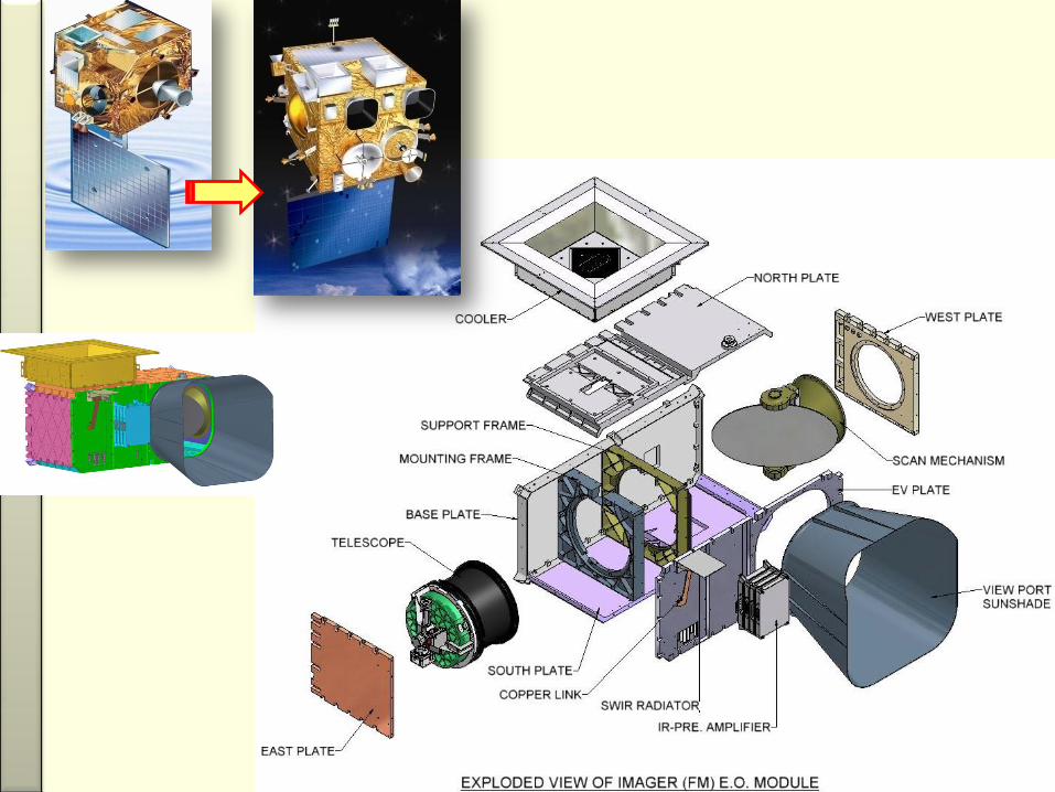
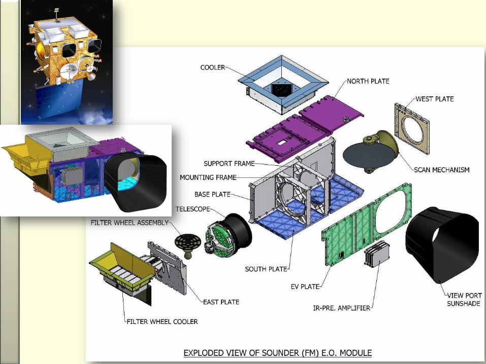
Telescope, structure, hood, field correcting optics (FCO), spectrometers, array
detectors, cooler assemblies, camera electronics, control and data handling
electronics, power electronics

PRIMARY MIRROR 700 mm
SECONDARY
MIRROR
FCO
HyS-VNIR
HyS-SWIR
MX-VNIR
MX-LWIR
FORE OPTICS AFT OPTICS FOCAL PLANES
RADIATION
FROM EARTH

Sec. Mirror
CFRP Cylinder
PFD –Payload Fixation Device
Telescope mounting interface with S/c
Optical bench
Prim. Mirror
The collecting optics
is based on
CARTOSAT-2A type
telescope with
700mm aperture
and nearly 5625 mm
effective focal
length.
IGFOV varied from
50 m to 1.5 km
whereas it is 1 km
for VNIR (CCD) for
Kalpana-1 & INSAT-
3A and 8km for
LWIR. For INSAT-3D
it is 4 km for LWIR.

Platform stability & operational requirement-S/c pointing accuracy : 0.05 deg in all axes-Drift rate : 5 X 10⁻⁵ deg/sec-Jitter requirement : <0.15 µrad (total)-Scan rate : 0.004 – 0.4 deg/sec-Turn around time : <30 secs-House-keeping (including SADA) : <5 min every 0.5 hours
Payload Operating Temperature requirements- HYS SWIR Detector : 273 K- SWIR IDCA window +Baffle : 273 ± 0.1 K- MX LWIR Detector : 240 K- LWIR FCO & IDCA window : 240 ± 0.15 K- IDCAs case (LWIR, SWIR) : 22 ± 5 deg C- MX -VNIR, HYS - VNIR Detector : 22 ± 2 deg C- Temperature gradient across telescope : <5 deg. C
Freq.
(Hz)
Integrated
rms jitter
(°)
> 2 < 1.9E-4
> 8 < 5.1E-5
> 13 < 3.1E-5
> 60 < 6.6E-6
Payload Requirements….…

VIEW FROM AEV SIDE OF OPTICAL BENCH, PAYLOAD
HEAT PIPES MOUNTEDBELOW PACKAGES
HEAT PIPES CONTECTEDWITH N/S RADIATORS
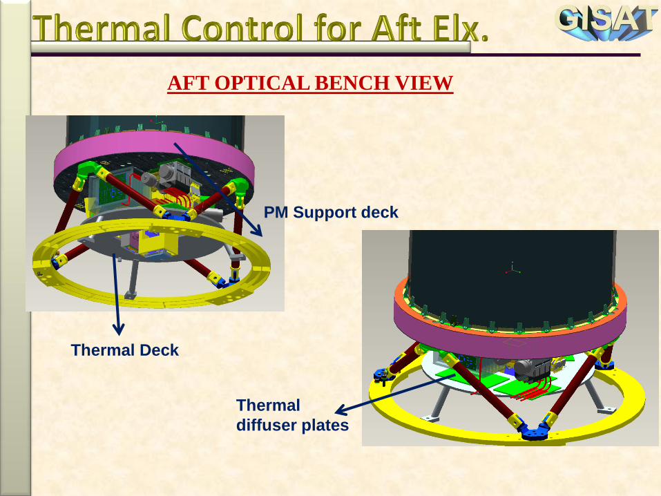
AFT OPTICAL BENCH VIEW
Thermal Deck
PM Support deck
Thermal
diffuser plates

1818

1818 1010

1818 1010
55

1818 1010
55 3000km3000km 1000km1000km
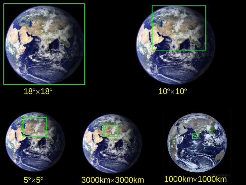
1818 1010
55 3000km3000km 1000km1000km

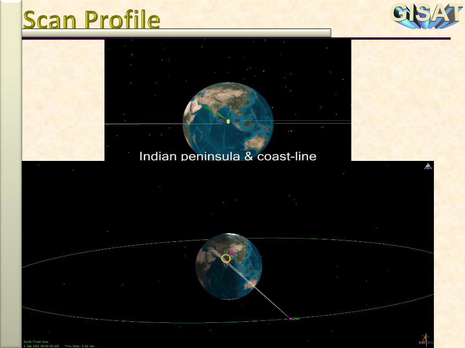
Scan Profile….
• Successive W-E and E-W strip has 5%
overlap
• N-S step size is dictated by band having
minimum swath
• Scan rate can be programmed to any value
between 0.004/s to 0.4/s• Imaging operations will not be carried
out for two hours around midnight

Coverage area
(km2)Bands Scan rate (/s) Time (min.)
6000 6000 MX-LWIR 0.4 17
3000 3000 MX-LWIR 0.4 7
3000 3000MX-VNIR and MX-
LWIR0.012 84
1000 1000MX-VNIR and MX-
LWIR0.012 13
1000 3000 All four 0.01 119
1000 1000 All four 0.004 94
Scan Time & Performance
Bands SWR (%) SNR
MX-VNIR 10 200
HyS-VNIR 40 400
HyS-SWIR 20 400
MX-LWIR 20500 mK NEdT for
300K target

BandChannels
(µm)
Spatial
sampling
(meter)
Swath (km)
MX-VNIR
0.45 - 0.52
0.52 - 0.59
0.62 - 0.68
0.71 - 0.74
0.77 - 0.86
0.845 - 0.875
50 490
HyS-VNIR0.4 - 0.87
~ 5 nm500 160
HyS-SWIR0.9 - 2.5
~ 7 nm500 190
MX-LWIR
7.1 - 7.6
8.3 - 8.7
9.4 - 9.8
10.3 - 11.3
11.5 - 12.5
13.0 - 13.5
1500 370
EW
S
N
S
W
A
T
H
SPATIAL
SAMPLE
SCAN

East-west separation between extreme focal
planes is about 1000 km Scale is only indicative
SCAN

High resolution Mx and Hyper-spectral on one platform.
Wide spectral range: VNIR to LWIR (0.4 to 13.5µM)
Different scan rates for different bands for optimizing scan time and SNR
All spectral bands / channels chosen after extensive discussions with the user teams at SAC
Several iterations on Payload and Spacecraft for optimized configuration Typical operation sequence generated based upon user
feedback
Keep Out Time (KOT) of ±2hrs local midnight for thermal management.
Reception at multiple stations is considered as a part of the system design
Payload components / subsystems are at advanced stage of procurement
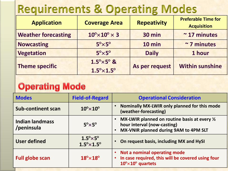
Application Coverage Area RepeativityPreferable Time for
Acquisition
Weather forecasting 1010 3 30 min ~ 17 minutes
Nowcasting 55 10 min ~ 7 minutes
Vegetation 55 Daily 1 hour
Theme specific1.55 &
1.51.5As per request Within sunshine
Modes Field-of-Regard Operational Consideration
Sub-continent scan 1010• Nominally MX-LWIR only planned for this mode
(weather-forecasting)
Indian landmass /peninsula
55• MX-LWIR planned on routine basis at every ½
hour interval (now-casting)• MX-VNIR planned during 9AM to 4PM SLT
User defined1.55
1.51.5• On request basis, including MX and HySI
Full globe scan 1818• Not a nominal operating mode• In case required, this will be covered using four
1010 quartets

Cameras Operating Modes
Coverage Area BandsScan Rate(/s)
Time *min.)
Reason for choosing ScanRate
1010(~6000Km x6000Km)
MX-LWIR 0.4 (Max) 17Optimum operating rate forMX-LWIR
55(~3000Km x3000Km)
MX-LWIR 0.4 7Optimum operating rate forMX-LWIR
55(~3000Km x3000Km)
MX-VNIRand MX-LWIR
0.012 84 Fast Coverage
55(~3000Km x3000Km)
All four 0.01 242Max. operating rate for HyS-VNIR
1.55(~1000Km x3000Km)
All four 0.01 119Max. operating rate for HyS-VNIR
1.51.5(~1000Km x1000Km)
All four 0.004 ( Min) 94 Good SNR
* Includes 5% overlap between successive E-W line
Excludes spacecraft turn around time

Swath in various Operating Modes
Scan Direction E/W
Nth E/W Scan
( N/S step = 160
KM)
(N+ 1)th E/W Scan
HyS-
VNIRHyS-
SWIR495
KM
190 KM160 KM 475 KM
Data corresponding to Lowest Swath Detector will be
transmitted : In above example HyS-VNIR has lowest swath,
so data of of 160 km swath for all channels ( with approx. 5%
overlap in sucessive scan will be transmitted)

3.5°
On-orbit : Solar panel Power generation is reduced due to
± 3.5° inclined orbit operations0.5 hours non-rotation of SADA9° panel offset due to Payload operations
9°

Down link freq. band (Ku-Band) 12.25 – 12.45 GHz
Orbital slot 93.5 ˚ East
Information Data rate 228 Mbps
Modulation QPSK (FEC 7/8)
Required EIRP 45 dBW
Link BER 1 * 10-8 @ 7 dB Eb/No
GND. Station antenna dia. 11m (G/T : 36 dB/ K)
GND. Station location Hyderabad, Ahmedabad, New Delhi
For both 0 deg & 180 deg YAW Flipping,
(Communication link 36db/K G/T considered for
ground station.)
Electronic Steered Antenna
Phased Array Antenna having 8 8 radiating elements.
Linear vertical Polarizatiosn
Cross Polarization Isolation : 28dB
Data Tx. Major Spec.….…
Parameters For GS
Antenna
11m
Path Loss 205.98 dB
Rain Attenuation 6 dB
Antenna pointing loss 1.5 dB
Implementation Margin 2 dB
Downlink Eb/No (G/T) 11.4 dB
Required Eb/No (G/T) 7 dB
Margin 4.4 dB
Link Budget

Irrespective of camera pointing on Earth
globe, the Antenna beam pointing is
always at the same location
Electronically steerable Antenna (PAA)
High Data rate transmission in Ku band (~228Mbps)
Imaging area (camera pointing)
Antenna beam pointing
Phased Array Antenna (PAA)…
BEAM SCANNING OVER
GLOBAL COVERAGE

Conventional C-band TTC-RF system TTC Frequencies:
TM: 4186.848MHz / 4189.344MHzTC : 6415.000MHz / 6421.480MHz
Orbital slot is 93.5oE• Co-located with INSAT-3A, INSAT-4B & GSAT-15
Receivers are ON continuously (Hot redundancy)
Tele-commanding through Omni antenna
Telemetry available through- High power mode through Omni Antenna- Low power mode through Medium Gain Antenna
(beam width 25 )- Payload link

Subsystem MASS (in kg.)
Optics + Electronics Payload Segment 215.0* Communication Payload Segment 83.0 Structure (includes 5 kg of passive isolator for wheel) 145.0Mechanisms (including yoke) 13.9Thermal Control System 65.0Propulsion System 131.0TTC-RF 15.7Attitude Orbital Control System & OBC 52.6Sensors 12.0Inertial System 66.0Power System 97.6 Integration 70.0Implementation Margin 10.2 Spacecraft Dry Mass 977.0 Propellant 1119.5 Pressurant 3.5Spacecraft Lift-Off Mass 2100.0

Subsystems/ Parameters GTO On Orbit
SS Eqn. Eclipse
Payload 0 640 640 640
Main Frame 182 532 533 341
Thermal 250 250 250 150
Battery Charging 40 0 150 0
One String Margin 0 94 102 0
Total Requirements 472 1516 1675 1131
Power Generation (nominal) 2200 1910 2105 1400
Power Generation for following Conditions:
(9 deg panel offset due to payload operations
+ 3.5 deg inclined orbit operations
+ 0.5 hour non-rotation of SADA)
NA 1626 2037 NA
Available Margin 1728 110 362 269
Subsystems GTO On Orbit
SS Eqn. Eclipse
Power Electronics 15 20 20 20
TTC-Tx 44 28 28 28
TTC-Rx 20 20 20 20
OBC 48.6 66 66 66
Magnetic Torquer 0 27 27 27
RLG (ILG-300)(*)/ FOG 35 35 35 35
5 RWs +WDE (0.3NM,15NMS) 0 290 290 100
SADA 0 16 16 16
Star Sensor (Mark -3; 2 APU+3-CHU) 14 14 14 14
Integration loss 5 16 17 15
Total 181.6 532 533 341

SUMMARY OF THE PROPELLANT BUDGET
Attitude Hold + EW SK : 70 m/s
Station Acquisition : 10 m/s
Repositioning & De-orbiting : 20 m/s
Launcher Dispersion Margin : 100 m/s
Additional Delta-V Margin : 280m/s
No NSSK is planned, but margin exists so if required itcan be planned.
GISAT-2 will be repeat of GISAT-1.

for your kind attention !


![Teesri Lehar by Alvin Toffler [Pdfstuff.blogspot.com]](https://static.fdocuments.us/doc/165x107/55cf9996550346d0339e2527/teesri-lehar-by-alvin-toffler-pdfstuffblogspotcom.jpg)