ALVIN II - 26th Intelligent Ground Vehicle Competition Control system The motor control was achieved...
14
1 NINTH ANNUAL INTERNATIONAL GROUND VEHICLE COMPETITION Design Report ALVIN II Trinity College Hartford, Connecticut May 18, 2001 Amir Tamrakar, Kundan Nepal, Andy Robinson, Joe Pentland, Trishan deLanerolle, Shyam Gouri Suresh, Marin Kobilarov, Sean Harris, Melissa Cordon and Nhon Trinh.
Transcript of ALVIN II - 26th Intelligent Ground Vehicle Competition Control system The motor control was achieved...

1
NINTH ANNUAL
INTERNATIONAL GROUND VEHICLE COMPETITION
Design Report
ALVIN II
Trinity College
Hartford, Connecticut
May 18, 2001
Amir Tamrakar, Kundan Nepal, Andy Robinson, Joe Pentland, Trishan deLanerolle,
Shyam Gouri Suresh, Marin Kobilarov, Sean Harris, Melissa Cordon and Nhon Trinh.

2
I. INTRODUCTION
ALVIN II is the product of a semester long project undertaken by the independent robot study team of the robotics lab at
Trinity College. The project essentially entailed building a semi-rugged autonomous vehicle based on a vision system. Members
of the study group received academic credit equivalent to a semester long engineering design class.
II. DESIGN
Design Objectives
The majority of the design objectives that were adhered to in the design and construction of ALVINII were as set by
IGVC. Additional design objectives were incorporated as deemed necessary.
1) Vehicle Dimensions: Length: 3ft: Width: less than 32 inches: Height 2 ft with the camera at 3 - 4 ft.
The robot needs to be able to go through standard doors that are 32 – 36 inches wide.
2) Vehicle weight without payload: not to exceed 110 lbs.
3) Payload: 20 lbs. Payload (18" x 8" x 8" )
4) Propulsion: The robot is to be driven by a bilateral stepper motor drive implementing differential steering. The
robot needs to be able to climb 20° inclines and move through sand.
5) Power: 12V lead-acid cells with a life of at least one hour run time.
6) Maximum speed: 3 mph.
7) Emergency stop:
a) Mechanical: at least 2ft. off the ground and very visible (Red mushroom type switch)
b) Remote: with an operating range of 300 ft.
c) Stopping Distance: 1m at maximum speed.
Emergency stop should keep the wheels braked so that it doesn’t roll off when stopped on a hill.
8) Sensory system: Vision system.
The vision system should process at least 10 frames per second to provide reliable control data. It should be able
to detect white lines painted on grass or paved road and detect obstacles from a distance of 3m. It should also
respond to the sudden appearance of objects at a close distance by signaling for an E-stop. It should also be able
to track an object in its field of view and provide some measure of the object which could be used to measure
distance to the object and its velocity.
9) Remote Control: Digital remote for 8-bit serial data transmission.
This will allow for 256 programmable commands and will be immensely useful for systems testing.
Design Process
Having enumerated these objectives, the next step was to subdivide the goals and devise a task list. The following Gantt
chart shows the task list and the distribution of the tasks over the semester. Approximate person hours spent on each task is also
noted.

3

4
The team was then broken down into three sub groups: Mechanical, Electrical and Software. The organization was as follows:
Team leader: Amir Tamrakar
1. Electrical Team: Amir Tamrakar, Kundan Nepal, Andy Robinson and Trishan DeLanarolle
2. Mechanical Team: Joe Pentland, Sean Harris, Kundan Nepal, Melissa Cordon and Nhon Trinh.
3. Software Team: Amir Tamrakar, Marin Kobilarov and Shyam Gouri Suresh
The team met every Thursday to present progress reports, performance data and problems encountered. It was a time for
brainstorming and modifying specifications.
III. SYSTEM DESCRIPTION
MECHANICAL:
Body Design:
The concept behind the design of the frame of the system was quite
simple: minimize the size and weight of the vehicle. To adhere to
IGVC contest guidelines, the length of the vehicle was made 3 ft.
Minimizing the vehicle weight required choosing a material that
was light yet rigid. 6061-T6 Aluminum extruded square tubing
was used for the frame because of its light weight, strength, low
cost, availability, and ease of machining. Perforated aluminum
sheets and plywood were joined to provide a vibration resistant
solid platform. Weather-proof synthetic material acquired from the
Pratt and Whitney surplus depot was attached to the body frame to form the exterior of the vehicle. The body is to be painted a
camouflage color. The top of the body frame is hinged to allow easy access to all the components and power switches.
Solid Works 2000 was used to model the vehicle in 3D. This allowed
for determining the configuration that made best use of the 3D space in the
body. It was also used for determining the center of gravity of the vehicle.
Drive System:
Two 15” recumbent bicycle wheels were acquired for the vehicle. These
wheels were chosen because they were sufficiently rugged and light weight.
The wheels were placed on a fixed shaft going across the robot and the wheel
hubs were threaded on to the shaft.
To meet the torque requirements it was necessary to provide a gear reduction.
A gear ratio of 5:1 is provided by a gearbox attached to the motors. This is then further geared down by a 3:1 ratio by the use of
timing belts.

5
Superior Electric Inc. and Intelligent Motion Systems were generous
enough to offer their support of this project through the donation of
stepper motors and motor controllers. The M2-3450-S motors have a
holding torque of 650 oz-in. and therefore can be used as brakes too.
The motors can be run at a maximum speed of 600 rpm after which
they lose torque due to resonance problems. This speed corresponds to
about 3 mph, the design target.
Payload Bay
The payload is to be strapped to the front of the vehicle as shown in the picture
below. It is then protected by the front hood.
ELECTRICAL SYSTEM:
System Block diagram for ALVIN II

6
Motor Control system
The motor control was achieved using a slave
micro-controller system. VESTA SBC2000-332
was used for this purpose. The micro-controller
has several serial communication ports and an
advanced Timing Processor Unit (TPU). The TPU generates the desired waveforms to drive the stepper motors. The serial ports
provide the basis for communication with the PIII PC and the remote control. The Remote Emergency Stop system is also wired
directly to this system so that an E-stop action
receives high priority directly in the controller
to bring the vehicle to a complete stop.
Two IM1007 micro-stepping controllers drive
the motors. This controller has a number of
advantages that were exploited with its use in
this project, namely, the high output current,
the 14 levels of microstepping, on-the-fly
microstep switching, and single power supply
for motor controller and motors.
COMPUTER SYSTEM:
ALVIN II's vision system software runs in Microsoft
Windows NT, so a computer capable of running the
operating system was necessary. In addition, the intense
calculations required for navigation required a relatively
powerful processor. To meet these needs, an Intel Pentium III
550 MHz processor was selected for its processing power and
relatively low cost. This computer is thus the master
computer. It communicates with the slave computer through
a serial communications port.
The system also had to be small enough to fit on
ALVIN II's body and as light as possible to avoid taxing the
motors. Since existing desktop systems are too large for use on the mobile platform and notebook computers were not flexible
enough, a custom system was assembled.

7
POWER SUPPLY:
This system provides power to the main computer, the slave
micro-controller, the motor controllers and the motors. The power
supply was set up as two independent systems: a high current 48V
DC supply for the motors, and a regulated 120V for the computer.
The 120V was generated from a 12V battery using a 300 W
power inverter
Given the fact that the motors require around 3A of current, an
operating time of just over an hour is expected from the 4.5Ah
batteries used.
VISION SYSTEM:
The Pentium III PC with a capture board, the camera and the UPS forms the vision system.
PCVision, a B/W image capture board manufactured by Imaging Technology, Inc was used
with a Pulnix TM-6702 progressive scan camera. The camera used for the vision system is
housed close to the center of rotation of ALVIN II about 3 ft. off the ground.
SOFTWARE:
Imaging Technology Inc.’s SHERLOCK32™ machine vision software is the development platform for the machine vision
applications. SHERLOCK32™ is a very user-friendly software package within an intuitive GUI environment. It provides an
extensive array of image preprocessing and image analysis algorithms as well as basic SPC and impressive I/O control.
The final vision application software was written in Visual C++ and Visual Basic for the front end. The basis of these
applications was MVTOOLs, a C++ library provided by Imaging Technology. Maple and MATLAB were used as mathematical
tools to test different strategies.
ALVIN II Kinematics Simulator:
This software was designed with the idea of simulating the kinematics of ALVIN II on a computer during the construction phase
of the robot and bad winter weather, when it cannot be taken for test runs.
OpenGL was used to model a 3-D obstacle course producing a real time perspective display of the obstacle course on a
computer screen. The perspective display is the expected scene to be seen from ALVIN II. The simulator takes in control signals
from the ALVIN II’s main computer via the serial port. It uses these to produce the expected response of ALVIN II and the
resulting change in scenery.

8
The camera on ALVIN II is then positioned in front of the
desktop computer, and the perspective scene displayed on the
computer’s screen is filmed as if it were the real scene. The
simulator refreshes the screen at about 20Hz (every 50ms). The
capture time for PCVision is 50ms per frame and the vision
software takes more time for processing (100ms per frame) .
Hence the simulation is valid.
IV. VISUAL CONTROL STRATEGY
The vision system is the only sensory system on this robot so all the control strategies are based on visual cues. The following is a
brief description of each of the visual tasks.
Line following
The first step to line following is line
detection. This is achieved by intelligently
thresholding the image. Since the lines are
either white on the grass or yellow on paved
sections of the road, there is enough contrast
to extract it out of the image. The width of
the line in the thresholded image is measured
to ensure that other bright objects aren’t
interpreted as lines.
Once the lines are detected, a segment of the
line expected to be about 1m in front of the
robot is extrapolated. The point at which this
line meets the horizon (set during calibration) is taken to be the direction of the path. In order to stay on the path this point must
always be directly in front of the robot, that is, it must be in the center of the image. A PID control strategy is then implemented
on this error to make the necessary changes in heading to minimize the error (e). The PID algorithm provides a correction
function that will minimize the error in a smooth manner. The correction function shown here has Kp, Ki, and Kd values which
represent proportional gain, derivative gain and integral gain coefficients.

9
Pothole detection
Potholes are similar to the lines in that they are white circles painted on the grass. But this produces a thresholded object that is
significantly different in size than that produced by the line. This factor is used to distinguish the pothole from a line.
Obstacle detection
Possible obstacles are construction barrels and white
buckets. These have a different texture compared to the
grass. This has been used as a basis for detecting
obstacles. The figure below shows the segmented image
that highlights the obstacles. The problem with this
method is that it detects the paved section of the road as
an obstacle too. This has been solved by using an
additional thresholding strategy.
General Navigation strategy
Given the lane following an obstacle detection strategy, the obstacle course navigation strategy then becomes simple to devise.
The strategy undertaken is simply to follow a line until an obstacle or a pothole is encountered. In this event, we simply turn away
to the other side of the path and continue following on that side. In the event that we lose track of the line, we just keep going at
the current speed until we find the line again. This strategy also makes it possible to follow dashed lines on the track. In the event
of a ramp, the speed is to be reduced to increase the torque on the wheels to assist going over the ramp.
Dead-Ends and Traps
In the event of a dead end, defined to be a situation where the control algorithms provide conflicting controls, the vehicle is to be
stopped and put into reverse until the control deadlock is gone. Traps like a double barricade is to be handled by first slowing the
vehicle down to a crawl and performing more accurate measurements on the image to decide on the best path to take.
Follow the leader strategy
The strategy for this task is to first track the leader. The leader is recognized as the special pattern defined in the rules. Pattern
tracking will locate the leader. Control strategies based on the PID algorithm are then used to always keep this pattern in the
center of the screen so that the robot is always heading towards the leader. Measurement is then to be made of the leader to come
up with a measurement of the speed of the leader.
10
Visual E-Stop strategy
An optic flow field is defined as the projection on the image plane of the motion vectors in 3D space. At the operating speed of
the robot, the flow field is low and controlled. In the case of a person coming in front of the robot at a close distance, this field is
suddenly large. This can be used as a trigger for the control algorithms to perform an E-stop.
V. SAFETY CONSIDERATIONS
Safety is always an important factor in the design of a vehicle. ALVIN II has several design features that meet the safety
requirements.
The first is a big RED mushroom shaped push button located at the rear center about 2ft off the ground. Activating this
button will quickly and safety bring ALVIN II to a halt in about 1 second. The motors have a holding torque that can act as a
brake and thus will keep the robot from rolling down a hill if stopped in the middle of one.
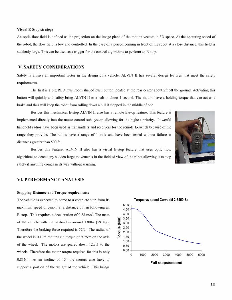
Besides this mechanical E-stop ALVIN II also has a remote E-stop feature. This feature is
implemented directly into the motor control sub-system allowing for the highest priority. Powerful
handheld radios have been used as transmitters and receivers for the remote E-switch because of the
range they provide. The radios have a range of 1 mile and have been tested without failure at
distances greater than 500 ft.
Besides this feature, ALVIN II also has a visual E-stop feature that uses optic flow
algorithms to detect any sudden large movements in the field of view of the robot allowing it to stop
safely if anything comes in its way without warning.
VI. PERFORMANCE ANALYSIS
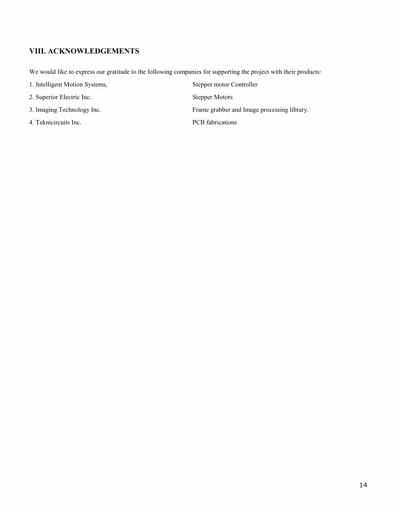
Stopping Distance and Torque requirements
The vehicle is expected to come to a complete stop from its
maximum speed of 3mph, at a distance of 1m following an
E-stop. This requires a deceleration of 0.88 m/s2. The mass
of the vehicle with the payload is around 130lbs (59 Kg).
Therefore the braking force required is 52N. The radius of
the wheel is 0.19m requiring a torque of 9.9Nm on the axle
of the wheel. The motors are geared down 12.3:1 to the
wheels. Therefore the motor torque required for this is only
0.81Nm. At an incline of 15° the motors also have to
support a portion of the weight of the vehicle. This brings
Torque vs speed Curve (M 2-3450-S)
0.00
0.50
1.00
1.50
2.00
2.50
3.00
3.50
4.00
4.50
5.00
0 1000 2000 3000 4000 5000 6000
Full steps/second
To
rqu
e (N
m)

11
the torque requirement up to about 3.1Nm. The plot shows the motor torque at various speeds. The holding torque of the motors is
around 4.5Nm. This means that the vehicle can be stopped quicker and at a shorter distance.
The shortest stopping distance achieved during testing without the motors losing torque was 20 cms.
Power Analysis and Battery Life:
The following plot shows the power drawn from the motor batteries at different speeds. The maximum power generated is at a
speed of around 400 full steps/sec, which is about 1Km/h. This is therefore the best speed to operate at.
Power Consumed
90
100
110
120
130
140
150
160
0 200 400 600 800 1000speed (steps/sec)
po
wer
(W
)
Current Drawn (at 48V)
1.5
1.7
1.9
2.1
2.3
2.5
2.7
2.9
3.1
0 200 400 600 800 1000
Speed (steps/sec)
Cu
rren
t (A
)
The second plot shows that the maximum current drawn is about 3Amps. So the 4.5 Ah batteries can be expected to have a life of
at least an hour as per the design requirements.
The main computer was powered by a 10Ah battery. The current drawn on the battery was about 3.9A during regular operation.
During heavy computation, the power drawn increased to a maximum of 6.13 A. This allows for over one hour of operation at
maximum computation load.
Resonance and Speed of Operation:
The maximum required speed of operation is 3mph, which is around 2700 full steps/sec. Since the torque decreases with speed,
at higher speeds the vehicle has to accelerate slower in order to ensure that the motors don’t torque out. At low speeds (100-140
steps/sec), motor resonance affects the performance of the vehicle reducing the torque drastically. During acceleration, care has
been taken to avoid these resonance speeds. As described above, the maximum power transfer is at a speed of around 400 steps
per second, which has been chosen as the operating speed.
Ramp climbing ability
On the ramps, the vehicle has to support a part of its weight so not all the torque generated by the motors can be used to
accelerate. Assuming that the vehicle is moving at a constant speed up a 15° ramp, the torque required, to keep it going, is around

12
2.3Nm. Therefore referring to the torque vs. speed curve, the ramp can only be climbed at speeds less than 1700 steps/sec. It is
always safer to go at a slower speed. A tilt sensor is to be employed to determine whether the robot is on a ramp.
Debris management
Debris on the track is a major problem because it raises the torque requirement of the motor by an astronomical amount. The
radius of the wheel limits the size of the debris that can be climbed over. Assuming that the wheel can climb over the debris,
since the vehicle has a fixed axle, the motors have to lift a huge portion of the weight of the robot to get it over the debris. On a
ramp, this is a very big problem. Debris can be in the form of little tufts of grass or uneven ground.
The largest debris ALVIN II could climb over was 3 inches high. The caster had a little problem getting over this debris
because it was light enough to be dragged with it. The field tests showed that it could climb over deeply sunk tire tracks.
Optics
The camera is at a height of 3ft from the ground. The varifocal lens on the camera has a range of 22° to54°. The camera is tilted
down to cover a distance of 4m in front of the robot. The iris and gain on it is manual. Changing lighting conditions, therefore,
could result in poor contrast. This can be taken care of in the software using equalization and normalization routines.
Line following
The performance of the line following algorithm is superb. The coefficients for the PID algorithm were derived by trial and error
on the simulator. Performance during the field tests matched the performance on the simulator to a great degree. Tracks left on the
grass by the wheels in the previous runs sometimes affected the line following algorithm during field tests.
Pothole detection
The pothole detection algorithm performed very well. Potholes were reliably differentiated from the lines and from the white
buckets.
Obstacle detection
The algorithm was set to detect the obstacles at a
distance of 3m from the robot. It performed well in
field tests. One problem in the earlier stages of
development was that the paved area of the track
was detected as a massive obstacle leading to dead
ends on the track. This was taken care of by
devising a new algorithm that combined the texture
segmenting algorithm with a thresholding algorithm.

13
Obstacle course navigation
In general the navigation algorithm performed satisfactorily. Obstacles and potholes were avoided without too many problems.
Double barricade traps and dashed lines on the course still present a problem. The robot tends to run away if the dashed lines
occur immediately after a big turn. This sometimes leads to the robot following the line outside the track. Work is in progress to
perfect the algorithm. Overall, each iteration of the algorithm takes less than 100ms so conforms to the design objective.
Follow the leader
This algorithm is currently in development. Object tracking is operational although not very reliable. The algorithm is slow and
work is in progress to develop reliable strategies to measure the speed of the leader.
E-stop
This feature is not yet reliable because computation of the optic flow field is a computationally intense task. At the moment it is
too slow to incorporate into the navigation algorithm.
VII. COST ESTIMATE
Item Cost Aluminum for body frame 50 PC (PIII 500 MHz) 500 Camera ( Pulnix TM-6702) 1000 Varifocal Lens 150 Batteries 200 Power Inverter 50 Stepper Motors 400* Motor Controllers 500* Wheels 50 Caster 15 Belts and Pulleys 50 Gearboxes 300* Covering material 20 Vesta microcontroller 200 Radio Transceiver chipset 30 PCB fabrication 200* Ham radios for the kill switch 30 TOTAL $3745
Note: * Indicates donated item
14
VIII. ACKNOWLEDGEMENTS
We would like to express our gratitude to the following companies for supporting the project with their products:
1. Intelligent Motion Systems, Stepper motor Controller
2. Superior Electric Inc. Stepper Motors
3. Imaging Technology Inc. Frame grabber and Image processing library.
4. Teknicircuits Inc. PCB fabrications