Aluminium Alloy Foams: Production and Properties...Aluminium Alloy Foams: Production and Properties...
28
3 Aluminium Alloy Foams: Production and Properties Isabel Duarte and Mónica Oliveira Centro de Tecnologia Mecânica e Automação, Departamento de Engenharia Mecânica, Universidade de Aveiro, Portugal 1. Introduction Ultra-light metal foams became an attractive research field both from the scientific and industrial applications view points. Closed-cell metal foams, in particular aluminium alloy (Al-alloy) ones can be used as lightweight, energy-absorption and damping structures in different industrial sectors, detaining an enormous potential when transportation is concerned. Despite the several manufacturing methods available, ultra-light metal foam applications seem to be restricted to a rather less demanding market in what concerns final product quality. The current available manufacturing processes enable effective control of density through process parameters manipulation. However, none of them allow for appropriate control of the cellular structures during its formation, leading to severe drawbacks in what concerns final product structural and mechanical properties. The latter, is undoubtedly the main reason for the lack of commercial acceptance of these ultra-light metal foams in product quality highly demanding sectors, such as the automotive or aeronautical sectors. The resolution of this problem is the main challenge of the scientific community in this field. To accomplish the latter two approaches may be followed: i) to develop new manufacturing processes or modify the existing ones to obtain foams with more uniform cellular structures. (ii) to understand and quantify the thermo-physico- chemical mechanisms involved during the foam formation in order to control the process, avoiding the occurrence of such imperfections and structural defects. Metal foams manufacturing processes seem to abound (Banhart, 2001) and can be classified in two groups (Banhart, 2006): direct and indirect foaming methods. Direct foaming methods start from a molten metal containing uniformly dispersed ceramic particles to which gas bubbles are injected directly (Körner et al, 2005), or generated chemically by the decomposition of a blowing agent (e.g. titanium hydride, calcium), or by precipitation of gas dissolved in the melt by controlling temperature and pressure (Zeppelin, 2003). The indirect foaming methods require the preparation of foamable precursors that are subsequently foamed by heating. The foamable precursor consists of a dense compacted of powders where the blowing agent particles are uniformly distributed into the metallic matrix. Most commercially available metal foams are based on alloys containing (Degischer & Kirst, 2002): aluminium, nickel, magnesium, lead, copper, titanium, steel and even gold. Among www.intechopen.com
Transcript of Aluminium Alloy Foams: Production and Properties...Aluminium Alloy Foams: Production and Properties...
3
Aluminium Alloy Foams: Production and Properties
Isabel Duarte and Mónica Oliveira Centro de Tecnologia Mecânica e Automação,
Departamento de Engenharia Mecânica, Universidade de Aveiro, Portugal
1. Introduction
Ultra-light metal foams became an attractive research field both from the scientific and
industrial applications view points. Closed-cell metal foams, in particular aluminium alloy
(Al-alloy) ones can be used as lightweight, energy-absorption and damping structures in
different industrial sectors, detaining an enormous potential when transportation is
concerned. Despite the several manufacturing methods available, ultra-light metal foam
applications seem to be restricted to a rather less demanding market in what concerns final
product quality. The current available manufacturing processes enable effective control of
density through process parameters manipulation. However, none of them allow for
appropriate control of the cellular structures during its formation, leading to severe
drawbacks in what concerns final product structural and mechanical properties. The latter,
is undoubtedly the main reason for the lack of commercial acceptance of these ultra-light
metal foams in product quality highly demanding sectors, such as the automotive or
aeronautical sectors. The resolution of this problem is the main challenge of the scientific
community in this field. To accomplish the latter two approaches may be followed: i) to
develop new manufacturing processes or modify the existing ones to obtain foams with
more uniform cellular structures. (ii) to understand and quantify the thermo-physico-
chemical mechanisms involved during the foam formation in order to control the process,
avoiding the occurrence of such imperfections and structural defects.
Metal foams manufacturing processes seem to abound (Banhart, 2001) and can be classified
in two groups (Banhart, 2006): direct and indirect foaming methods. Direct foaming
methods start from a molten metal containing uniformly dispersed ceramic particles to
which gas bubbles are injected directly (Körner et al, 2005), or generated chemically by the
decomposition of a blowing agent (e.g. titanium hydride, calcium), or by precipitation of gas
dissolved in the melt by controlling temperature and pressure (Zeppelin, 2003). The indirect
foaming methods require the preparation of foamable precursors that are subsequently
foamed by heating. The foamable precursor consists of a dense compacted of powders
where the blowing agent particles are uniformly distributed into the metallic matrix.
Most commercially available metal foams are based on alloys containing (Degischer & Kirst,
2002): aluminium, nickel, magnesium, lead, copper, titanium, steel and even gold. Among
www.intechopen.com
Powder Metallurgy 48
the metal foams, Al-alloys are commercially the most exploited ones due to their low
density, high ductility, high thermal conductivity and competitive cost. Some
manufacturing methods are already being commercialised. Direct foaming methods are
currently being commercial exploited in a large-scale, the following companies are just a few
examples. The Cymat Aluminium Corporation (in Canada) manufactures aluminium foams,
designated “stabilised aluminium foam” which is obtained by gas injected directly into a
molten metal (Degischer & Kirszt, 2002). Ceramic particles (e.g. silicon carbide, aluminium
oxide and magnesium oxide) are used to enhance the viscosity of the melt and to adjust its
foaming properties, since liquid metals cannot easily be foamed by the introduction of
bubbling air. The foamy mass is relatively stable owing to the presence of ceramic particles
in the melt. Foam panels with 1m in width and thickness range of 25-150 mm, can be
produced continuously without length limitations at production rates of 900 kg/hour. The
relative density of these foams is within the range 0.05-0.55 g/cm3. The average cell size is
2.5-30 mm. This process is the cheapest of all and allows for manufacturing large volume of
foams. Moreover, through this process it is possible to obtain low density foams. The main
disadvantage lies is the poor quality of the foams produced. The cell size is large and often
irregular, and the foams tend to have a marked density gradient. Despite this process
continuous improvement, the drawing of the foam and the size distribution of the pores are
still difficult to control. Besides its low production cost, secondary operations are usually
necessary. For example, the foamed material is cut into the required shape after foaming.
The machining of these foams can be problematic due the high content of ceramic particles
(10-30 vol. %) used in the process. Hütte Klein-Reichenbach Ges.m.b.H company (Austria)
also produces and commercialises aluminium foams with excellent cell size uniformity,
called MetComb. The process used is based on the gas injection method (Banhart, 2006) and
allows for the production of complex shaped parts by casting the formed foam into the
moulds.
An alternative way for foaming melts directly is to add a blowing agent to the molten metal.
The blowing agent decomposes under the influence of heat and releases gas which then
propels the foaming process. Shinko Wire Company has been manufacturing foamed
aluminium under the registered trade name “Alporas” with production volumes reported
as up to 1000 kg of foam per day, using a batch casting process (Miyoshi et al, 2000). This
method starts with the addition of 1.5 wt.% calcium metal into the molten aluminium at
680°C, followed by several minutes stirring to adjust viscosity. An increase of viscosity is
achieved by the formation of calcium oxides. After the viscosity has reached the desired
value, titanium hydride (TiH2) is added (typically 1.6 wt.%), as a blowing agent by releasing
hydrogen (H2) gas in the hot viscous liquid. The melt starts to expand slowly and gradually
fills the foaming vessel. The foaming takes place at constant pressure. After cooling the
vessel below the melting point of the alloy, the liquid foam turns into a solid Al foam. After
that, the foam block is removed from the mould, it is sliced into flat plates of various
thicknesses according to its end use. This process is capable of producing large blocks of
good quality. Blocks with 450 mm in width, 2050 mm in length and 650 mm in height can be
produced. These foams have uniform pore structure and do not require the addition of
ceramic particles, which makes it brittle. However, the method is more expensive than
foaming melts by gas injection method requiring more complex processing equipment. The
density range of these foams is 0.18-0.24 g/cm3, and the mean cell size is about 4.5 mm.
www.intechopen.com
Aluminium Alloy Foams: Production and Properties 49
Nowadays, foams manufactured by indirect foaming methods are also in the state of
commercial exploitation, but in small-scale by German and Austrian Companies, like
Schunk GmbH, Applied Light-weight Materials ALM and Austrian Company Alulight
GmbH (Banhart, 2006). Powder Metallurgical (PM) method is one of the commercially
exploited indirect methods to produce Al-alloy foams and it is also the research field of the
authors of this chapter. This process consists on the heating of a precursor material which is
obtained by hot compaction of a metal alloy (e.g. Al-alloy) with blowing agent powders (e.g.
TiH2), resulting in the foam itself. The metal expands, developing a highly internal porous
structure of closed-cells due to the simultaneous occurrence of the melting of the metal and
thermal decomposition of the blowing agent with the release of a gas (e.g. H2). The liquid
foam is then cooled in air, resulting in a solid foam with closed cells and with a very thin
dense skin that improves the mechanical properties of these materials. This process can
produce foams with porosities between 75% and 90%.
The PM method has several advantages in comparison with the methods described earlier
and will be further discussed ahead. The latter, has been addressed particularly in what
concerns two research lines: (i) the study of the physics and foaming technology, with
particular emphasis on dedicated process equipment development towards high quality
foams production. (ii) foam quality assessment through proper part property
characterisation, establishing its limits of application and seeking for new markets. This
chapter presents a detailed overview of the current state-of-art in what concerns to methods,
equipment and appropriate industrial procedures in order to obtain metal foams with good
quality. The advantages, the disadvantages and the limitations of this PM method are also
presented and discussed. An overview of the main challenges and perspectives in this field
concerning industrial implementation is also presented, whenever it is possible the authors
present novel research work.
2. Production of metal foams
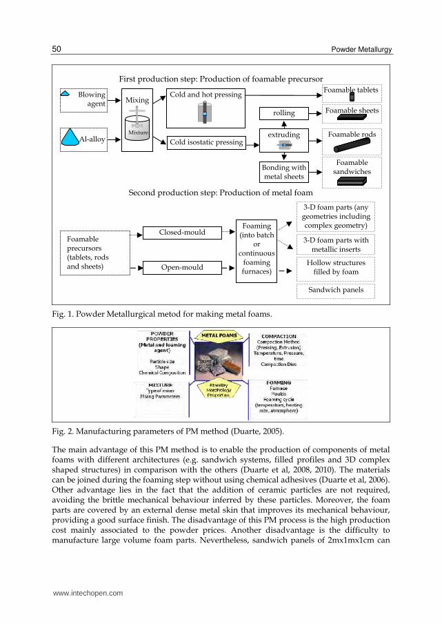
Metal foam production by PM method can be divided into two production steps: (i)
production of foamable precursor and (ii) production of the metal foam itself through the
foaming of precursor material. A schematic diagram of the PM method is shown in Fig. 1.
The first step is the preparation of a dense solid semi finished product called foamable
precursor. The latter is attained by compacting a powder mixture containing the blowing
agent and the metal, by using a conventional technique. The second step includes the
production of the metal foam by heating this foamable precursor at temperatures above its
melting temperature.
This PM method can be used to produce foams of different metals and its alloys (Degischer
&Kriszt, 2002), such as aluminium and its alloys, tin, zinc, lead, steel and gold, which is one
of the advantage of this PM method. Among all metal foams, the Al-alloys are the ones that
have received more attention from both the research community and industry, due to its
enormous potential mainly in what concerns specific weight and highly corrosion
resistance. The most studied Al-alloys for foaming are pure aluminium, wrought alloys (e.g.
6xxx alloy series) or casting alloys (e.g. AlSi7Mg). The high quality foams of these different
metals can be obtained by choosing the appropriate blowing agent. Moreover, the
manufacturing parameters of the different stages require appropriate adjustment (Fig. 2).
www.intechopen.com
Powder Metallurgy 50
Fig. 1. Powder Metallurgical metod for making metal foams.
Fig. 2. Manufacturing parameters of PM method (Duarte, 2005).
The main advantage of this PM method is to enable the production of components of metal foams with different architectures (e.g. sandwich systems, filled profiles and 3D complex shaped structures) in comparison with the others (Duarte et al, 2008, 2010). The materials can be joined during the foaming step without using chemical adhesives (Duarte et al, 2006). Other advantage lies in the fact that the addition of ceramic particles are not required, avoiding the brittle mechanical behaviour inferred by these particles. Moreover, the foam parts are covered by an external dense metal skin that improves its mechanical behaviour, providing a good surface finish. The disadvantage of this PM process is the high production cost mainly associated to the powder prices. Another disadvantage is the difficulty to manufacture large volume foam parts. Nevertheless, sandwich panels of 2mx1mx1cm can
extruding
Blowing agent
Al-alloy
Mixing
Cold isostatic pressing
Cold and hot pressingFoamable tablets
Foamable rods
Foamable sheets
Foamable precursors (tablets, rods and sheets)
Foaming (into batch
or continuous
foaming furnaces)
Closed-mould
Open-mould
3-D foam parts (any geometries including complex geometry)
Hollow structures filled by foam
Sandwich panels
Foamable sandwiches
3-D foam parts with metallic inserts
Mixture
rolling
Bonding with metal sheets
First production step: Production of foamable precursor
Second production step: Production of metal foam
www.intechopen.com
Aluminium Alloy Foams: Production and Properties 51
already be manufactured (Degischer & Kirst, 2002). Furthermore, it must be pointed out that during PM method it is still rather difficult to fully control the foaming process, which results in lack of uniformity of the pore structure.
2.1 Preparation of the foamable precursors
The first step of the PM method to obtain metal foams is the production of foamable precursor materials. The fundamental aspects of this production step are discussed ahead.
2.1.1 Selection of the powders
The blowing agent is a chemical compound which releases gas when heated, being the responsible for the formation of bubbles. There are two main requirements to obtain high quality foams. The first one is to ensure an uniform distribution of the blowing particles into the metal matrix within the precursor material. The second is to ensure the coordination of the thermal decomposition characteristics of the blowing agent and the alloy melting behaviour to avoid cracks’ formation before melting. The selection of these powders is therefore, detrimental for the foaming success. The characteristics of the metal powders, like the purity, the particle size, the alloying chemical elements (content and type) and the impurities (content and type), as well as the alloy melting behaviour and the thermal decomposition characteristics of the blowing agent must be studied and known. The literature highlights how powders from different manufactures could lead to notable differences in foaming behaviour (Baumgärtner et al, 2000; Degischer & Kirst, 2002).
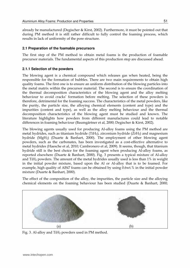
The blowing agents usually used for producing Al-alloy foams using the PM method are metal hydrides, such as titanium hydride (TiH2), zirconium hydride (ZrH2) and magnesium hydride (MgH2) (Duarte & Banhart, 2000). The employment of other blowing agent powders, such as the carbonates, has been investigated as a cost-effective alternative to metal hydrides (Haesche et al, 2010; Cambronero et al, 2009). It seems, though, that titanium hydride still is the best choice for the foaming agent when producing Al-alloy foams, as reported elsewhere (Duarte & Banhart, 2000). Fig. 3 presents a typical mixture of Al-alloy and TiH2 powders. The amount of the metal hydrides usually used is less than 1% in weight in the initial powder mixture, based upon the Al or Al-alloy that is to be foamed. For example, high quality of AlSi7 foams can be obtained by using 0.6wt.% in the initial powder mixture (Duarte & Banhart, 2000).
The effect of the composition of the alloy, the impurities, the particle size and the alloying chemical elements on the foaming behaviour has been studied (Duarte & Banhart, 2000;
(a) (b)
Fig. 3. Al-alloy and TiH2 powders used in PM method.
www.intechopen.com
Powder Metallurgy 52
Lehmus & Busse, 2004; Gokhale et al, 2007; Ibrahim et al, 2008; Helwig et al, 2011). Some of these effects on the foam expansion behaviour or cell structure have not yet been well established. A recent research of the effect of TiH2 particle size on the foaming behaviour and on the morphology of Al-alloy foam produced by PM process is reported (Ibrahim et al, 2008). These studies revealed that the use of the coarser particle sizes of TiH2 leads to a higher foam expansion and coarser macrostructure while the finer grade of TiH2 leads to a quite lower maximum expansion and a finer macrostructure. The use of different particle sizes is an approach to adapt the onset of gas evolution temperature of the gas blowing agent and improvement of the macrostructure of foamed aluminium.
The difference between thermal decomposition of the blowing agent and melting temperature of the metal may cause the formation of irregular, crack-like pores in early expansion stages, which then can lead to irregularities in the final foam (Duarte & Banhart, 2000). The research in this field has been demonstrating that the high-quality Al-alloy foam is obtained when this difference is minimised. The basic rules to choose the best blowing agent are related to the closing between the temperature of the beginning of the thermal decomposition of the blowing agent and the liquidus temperature of the metal. This problem has been approached in two different ways: (i) pre-treatments of the blowing agent powder to delay the hydrogen release, i.e. to shift it to higher temperatures, (ii) to change the alloy composition to obtain lower melting point through the addition of alloying elements.
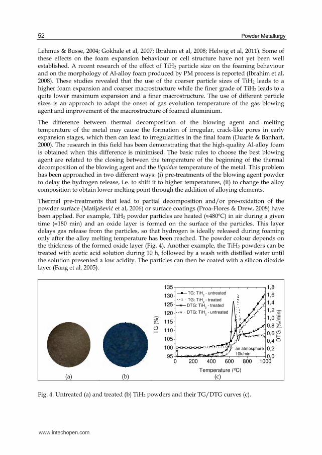
Thermal pre-treatments that lead to partial decomposition and/or pre-oxidation of the powder surface (Matijašević et al, 2006) or surface coatings (Proa-Flores & Drew, 2008) have been applied. For example, TiH2 powder particles are heated (480ºC) in air during a given
time (180 min) and an oxide layer is formed on the surface of the particles. This layer delays gas release from the particles, so that hydrogen is ideally released during foaming only after the alloy melting temperature has been reached. The powder colour depends on the thickness of the formed oxide layer (Fig. 4). Another example, the TiH2 powders can be treated with acetic acid solution during 10 h, followed by a wash with distilled water until the solution presented a low acidity. The particles can then be coated with a silicon dioxide layer (Fang et al, 2005).
0 200 400 600 800 100095
100
105
110
115
120
125
130
135
air atmosphere
10k/min
TG: TiH2 - untreated
TG: TiH2 - treated
TG
(%
)
Temperature (ºC)
0,0
0,2
0,4
0,6
0,8
1,0
1,2
1,4
1,6
1,8
DTG: TiH2 - treated
DTG: TiH2 - untreated
DT
G (
%/m
in)
(a) (b) (c)
Fig. 4. Untreated (a) and treated (b) TiH2 powders and their TG/DTG curves (c).
www.intechopen.com
Aluminium Alloy Foams: Production and Properties 53
Another strategy is to change the alloy composition to obtain lower melting temperatures through the addition of alloying elements, such as the magnesium, zinc and copper that decreases the melting temperature (Helwig et al, 2011). Although this strategy appears to be promising, research in this field has not been very systematic. The results revealed that these treatments form a sufficiently thick oxide layer which leads to a minimum of hydrogen loose. Helwig et al reported that the use of even higher magnesium amounts was found out to lead to promising results in the run-up to this study. Researchers have been testing the addition of the ceramic particles (e.g. alumina) in the initial powder mixture to improve the foaming stability through the increase of the melt bulk viscosity (Kennedy, 2004). However, the presence of these particles can originate a brittle mechanical behaviour of the foams.
2.1.2 Mixing of the powders
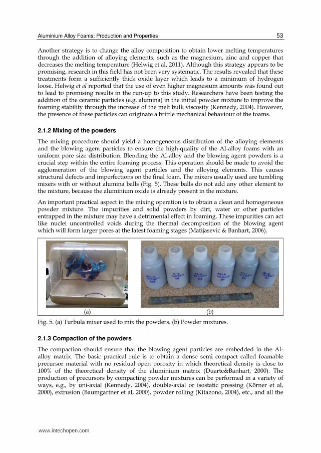
The mixing procedure should yield a homogeneous distribution of the alloying elements and the blowing agent particles to ensure the high-quality of the Al-alloy foams with an uniform pore size distribution. Blending the Al-alloy and the blowing agent powders is a crucial step within the entire foaming process. This operation should be made to avoid the agglomeration of the blowing agent particles and the alloying elements. This causes structural defects and imperfections on the final foam. The mixers usually used are tumbling mixers with or without alumina balls (Fig. 5). These balls do not add any other element to the mixture, because the aluminium oxide is already present in the mixture.
An important practical aspect in the mixing operation is to obtain a clean and homogeneous powder mixture. The impurities and solid powders by dirt, water or other particles entrapped in the mixture may have a detrimental effect in foaming. These impurities can act like nuclei uncontrolled voids during the thermal decomposition of the blowing agent which will form larger pores at the latest foaming stages (Matijasevic & Banhart, 2006).
(a) (b)
Fig. 5. (a) Turbula mixer used to mix the powders. (b) Powder mixtures.
2.1.3 Compaction of the powders
The compaction should ensure that the blowing agent particles are embedded in the Al-alloy matrix. The basic practical rule is to obtain a dense semi compact called foamable precursor material with no residual open porosity in which theoretical density is close to 100% of the theoretical density of the aluminium matrix (Duarte&Banhart, 2000). The production of precursors by compacting powder mixtures can be performed in a variety of ways, e.g., by uni-axial (Kennedy, 2004), double-axial or isostatic pressing (Körner et al, 2000), extrusion (Baumgartner et al, 2000), powder rolling (Kitazono, 2004), etc., and all the
www.intechopen.com
Powder Metallurgy 54
above mentioned techniques can be hot or cold. A conjugation of different conventional compaction techniques can be used. Furthermore, the compacting process can be performed in an inert atmosphere, in air or in vacuum (Jiménez et al, 2009). The most economical way is the double-axial pressing in air, but the most efficient one is the high-temperature extrusion. There are several procedures to produce foamable precursors. A simple process is to compact the powder mixture using a hot uniaxial pressing at temperatures close to the thermal decomposition of the blowing agent, using a pressing device and a die with a heating system (Fig. 6). This process enables to yield more than 99% relative density of the precursor (Fig. 7a).
Fig. 6. Die with the heating system used to prepare the precursor material.
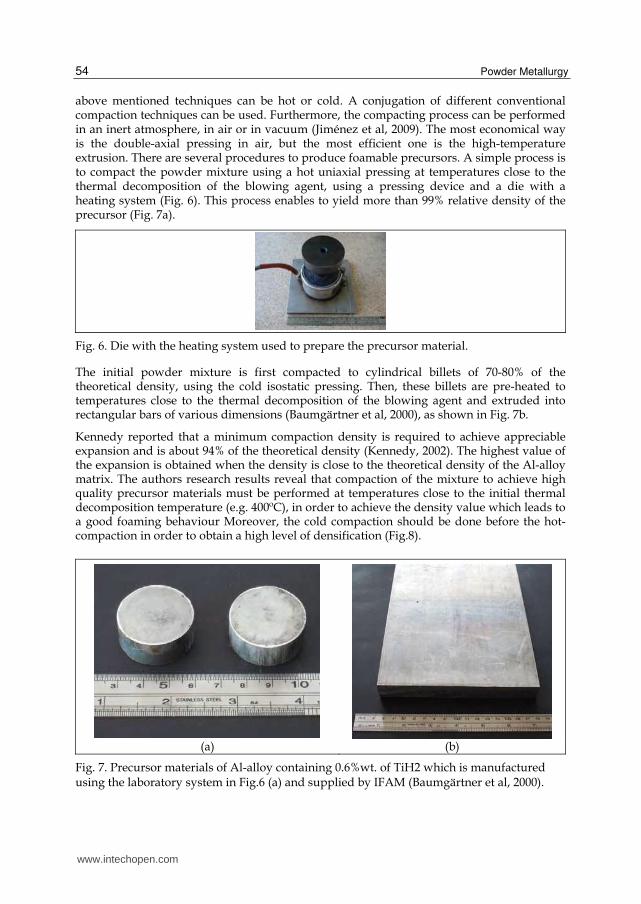
The initial powder mixture is first compacted to cylindrical billets of 70-80% of the theoretical density, using the cold isostatic pressing. Then, these billets are pre-heated to temperatures close to the thermal decomposition of the blowing agent and extruded into rectangular bars of various dimensions (Baumgärtner et al, 2000), as shown in Fig. 7b.
Kennedy reported that a minimum compaction density is required to achieve appreciable expansion and is about 94% of the theoretical density (Kennedy, 2002). The highest value of the expansion is obtained when the density is close to the theoretical density of the Al-alloy matrix. The authors research results reveal that compaction of the mixture to achieve high quality precursor materials must be performed at temperatures close to the initial thermal decomposition temperature (e.g. 400ºC), in order to achieve the density value which leads to a good foaming behaviour Moreover, the cold compaction should be done before the hot-compaction in order to obtain a high level of densification (Fig.8).
(a) (b)
Fig. 7. Precursor materials of Al-alloy containing 0.6%wt. of TiH2 which is manufactured using the laboratory system in Fig.6 (a) and supplied by IFAM (Baumgärtner et al, 2000).
www.intechopen.com
Aluminium Alloy Foams: Production and Properties 55
(a) (b) (c)
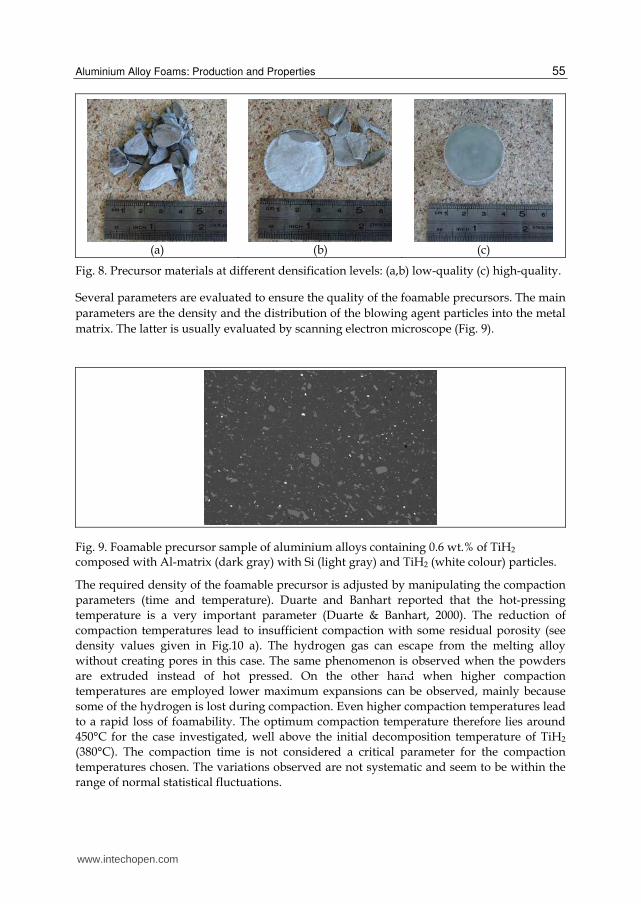
Fig. 8. Precursor materials at different densification levels: (a,b) low-quality (c) high-quality.
Several parameters are evaluated to ensure the quality of the foamable precursors. The main
parameters are the density and the distribution of the blowing agent particles into the metal
matrix. The latter is usually evaluated by scanning electron microscope (Fig. 9).
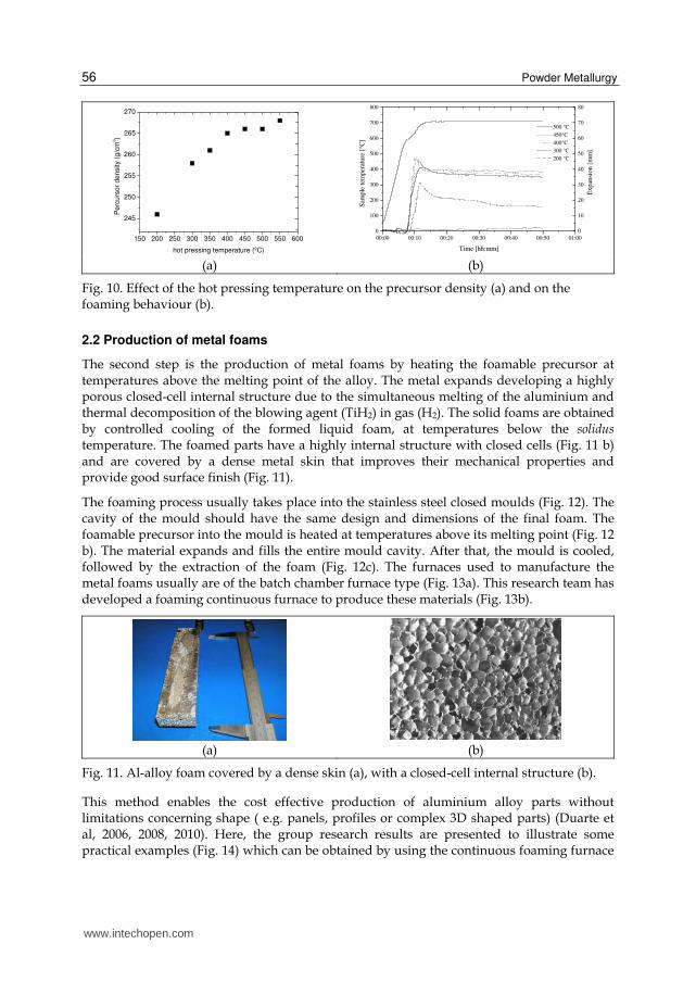
Fig. 9. Foamable precursor sample of aluminium alloys containing 0.6 wt.% of TiH2 composed with Al-matrix (dark gray) with Si (light gray) and TiH2 (white colour) particles.
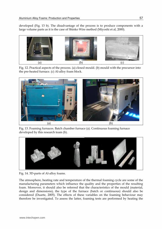
The required density of the foamable precursor is adjusted by manipulating the compaction
parameters (time and temperature). Duarte and Banhart reported that the hot-pressing
temperature is a very important parameter (Duarte & Banhart, 2000). The reduction of
compaction temperatures lead to insufficient compaction with some residual porosity (see
density values given in Fig.10 a). The hydrogen gas can escape from the melting alloy
without creating pores in this case. The same phenomenon is observed when the powders
are extruded instead of hot pressed. On the other hand when higher compaction
temperatures are employed lower maximum expansions can be observed, mainly because
some of the hydrogen is lost during compaction. Even higher compaction temperatures lead
to a rapid loss of foamability. The optimum compaction temperature therefore lies around
450°C for the case investigated, well above the initial decomposition temperature of TiH2
(380°C). The compaction time is not considered a critical parameter for the compaction
temperatures chosen. The variations observed are not systematic and seem to be within the
range of normal statistical fluctuations.
200m
www.intechopen.com
Powder Metallurgy 56
150 200 250 300 350 400 450 500 550 600
245
250
255
260
265
270
Pe
rcu
rso
r den
sity (
g/c
m3)
hot pressing temperature (ºC)
00:00 00:10 00:20 00:30 00:40 00:50 01:00
0
100
200
300
400
500
600
700
800
Sam
ple
tem
per
ature
[°C
]
Time [hh:mm]
0
10
20
30
40
50
60
70
80
500 °C
450°C
400°C
300 °C
200 °C
Expan
sion [
mm
]
(a) (b)
Fig. 10. Effect of the hot pressing temperature on the precursor density (a) and on the foaming behaviour (b).
2.2 Production of metal foams
The second step is the production of metal foams by heating the foamable precursor at temperatures above the melting point of the alloy. The metal expands developing a highly porous closed-cell internal structure due to the simultaneous melting of the aluminium and thermal decomposition of the blowing agent (TiH2) in gas (H2). The solid foams are obtained by controlled cooling of the formed liquid foam, at temperatures below the solidus temperature. The foamed parts have a highly internal structure with closed cells (Fig. 11 b) and are covered by a dense metal skin that improves their mechanical properties and provide good surface finish (Fig. 11).
The foaming process usually takes place into the stainless steel closed moulds (Fig. 12). The cavity of the mould should have the same design and dimensions of the final foam. The foamable precursor into the mould is heated at temperatures above its melting point (Fig. 12 b). The material expands and fills the entire mould cavity. After that, the mould is cooled, followed by the extraction of the foam (Fig. 12c). The furnaces used to manufacture the metal foams usually are of the batch chamber furnace type (Fig. 13a). This research team has developed a foaming continuous furnace to produce these materials (Fig. 13b).
(a) (b)
Fig. 11. Al-alloy foam covered by a dense skin (a), with a closed-cell internal structure (b).
This method enables the cost effective production of aluminium alloy parts without limitations concerning shape ( e.g. panels, profiles or complex 3D shaped parts) (Duarte et al, 2006, 2008, 2010). Here, the group research results are presented to illustrate some practical examples (Fig. 14) which can be obtained by using the continuous foaming furnace
www.intechopen.com
Aluminium Alloy Foams: Production and Properties 57
developed (Fig. 13 b). The disadvantage of the process is to produce components with a large volume parts as it is the case of Shinko Wire method (Miyoshi et al, 2000).
(a) (b) (c)
Fig. 12. Practical aspects of the process. (a) closed mould. (b) mould with the precursor into the pre-heated furnace. (c) Al-alloy foam block.
(a) (b)
Fig. 13. Foaming furnaces. Batch chamber furnace (a). Continuous foaming furnace developed by this research team (b).
Fig. 14. 3D-parts of Al-alloy foams.
The atmosphere, heating rate and temperature of the thermal foaming cycle are some of the manufacturing parameters which influence the quality and the properties of the resulting foam. Moreover, it should also be referred that the characteristics of the mould (material, design and dimensions), the type of the furnace (batch or continuous) should also be considered (Duarte, 2005). The effects of these variables on the foaming behaviour may therefore be investigated. To assess the latter, foaming tests are performed by heating the
www.intechopen.com
Powder Metallurgy 58
precursor material up to its melting point inside of the apparatus called laser expandometer, which was specially developed and constructed for this purpose (Fig. 15). Here, the expansion (volume) and its temperature are monitored by means of a laser sensor and thermocouple, respectively. The measurement of the volume of the expanding melt together with the sample temperature generates a pair of functions V(t) and T(t) which characterise the foaming kinetics. The foaming process is strongly governed by temperature effects (Duarte & Banhart, 2000). The expansion curve is strongly dependent on the processing conditions, mainly on the hot pressing temperature to obtain the foamable precursor material, and the heating parameters during foaming (Fig. 10 b and Fig. 16).
Fig. 15. Laser expandometer used to characterise the foaming kinetics.
00:00 00:10 00:20 00:30 01:00 01:30 02:00 02:300
10
20
30
40
50
60
Exp
ansi
on [m
m]
Time [hh:mm]
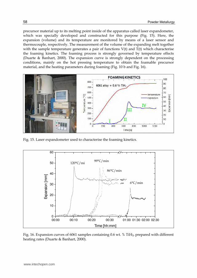
Fig. 16. Expansion curves of 6061 samples containing 0.6 wt. % TiH2, prepared with different heating rates (Duarte & Banhart, 2000).
120°C/mi99°C/min
86°C/min
6°C/min
www.intechopen.com
Aluminium Alloy Foams: Production and Properties 59
The final quality of the metal foams is evaluated by characterising its properties, namely the density, structural and mechanical properties. The foam density is relatively predictable and controlled by manipulation of the manufacturing parameters (Duarte & Banhart, 2005). Higher heating rates lead to an earlier expansion of the foamable precursor because the melting temperature is reached at an earlier time (Fig. 16). Besides that, the three expansion curves for the highest heating rates are quite similar. Only significantly lower heating rates lead to a change of the expansion characteristics, namely a lower maximum expansion. The reason for this may be the gas losses due to diffusion of hydrogen and perhaps the strong sample oxidation which might hinder expansion. In general, higher heating rate of the foamable precursor leads to the formation of foams with lower density.
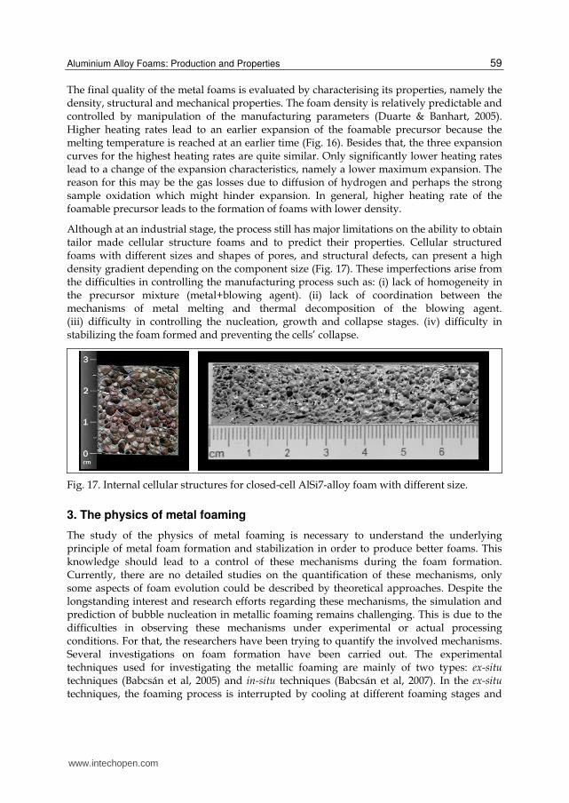
Although at an industrial stage, the process still has major limitations on the ability to obtain tailor made cellular structure foams and to predict their properties. Cellular structured foams with different sizes and shapes of pores, and structural defects, can present a high density gradient depending on the component size (Fig. 17). These imperfections arise from the difficulties in controlling the manufacturing process such as: (i) lack of homogeneity in the precursor mixture (metal+blowing agent). (ii) lack of coordination between the mechanisms of metal melting and thermal decomposition of the blowing agent. (iii) difficulty in controlling the nucleation, growth and collapse stages. (iv) difficulty in stabilizing the foam formed and preventing the cells’ collapse.
Fig. 17. Internal cellular structures for closed-cell AlSi7-alloy foam with different size.
3. The physics of metal foaming
The study of the physics of metal foaming is necessary to understand the underlying principle of metal foam formation and stabilization in order to produce better foams. This knowledge should lead to a control of these mechanisms during the foam formation. Currently, there are no detailed studies on the quantification of these mechanisms, only some aspects of foam evolution could be described by theoretical approaches. Despite the longstanding interest and research efforts regarding these mechanisms, the simulation and prediction of bubble nucleation in metallic foaming remains challenging. This is due to the difficulties in observing these mechanisms under experimental or actual processing conditions. For that, the researchers have been trying to quantify the involved mechanisms. Several investigations on foam formation have been carried out. The experimental techniques used for investigating the metallic foaming are mainly of two types: ex-situ techniques (Babcsán et al, 2005) and in-situ techniques (Babcsán et al, 2007). In the ex-situ techniques, the foaming process is interrupted by cooling at different foaming stages and
www.intechopen.com
Powder Metallurgy 60
the resulting solid foam is characterized. The disadvantage of this approach is that it takes a long time to carry out such investigation, and that the results suffer from a certain inaccuracy originating statistical variations between a single experiment. Even if the starting materials for the individual foaming tests were produced in the same way, each foaming experimental test would turn out slightly differently, due to effects such as agglomerates of the blowing agent particles, structural defects and impurities in the precursor (Duarte, 2005). The 3D-image of X-ray tomographic observations of solid foam samples in different foaming stages allow to observe the modification of the shape of the bubbles (Stanzick et al, 2002).
In the in-situ techniques, the foaming studies are evaluated during the evolution of one single sample (Garcia-Moreno et al, 2005; Rack et al, 2009). Neutron radioscopy and X-ray radioscopy were employed for in situ observation drainage mechanisms, the early stages and growth stages, during the foaming process (Bellman et al, 2002). The temporal development of the cellular structures of liquid metallic foams and the redistributions of the metal can be observed by synchrotron based on neutron radioscopy.
Theoretical studies of the foaming process itself concentrate predominantly on the detailed analysis of microscopic evolution of foams, mostly on the basis of an already existing cellular structure (Stavans, 1993). A theoretical study on metal foam processing has treated the material flow behaviour and focused on the description of the solidification stage during the process using an one-dimensional model which combines the equations of foam drainage with Fourier equation. However, this model is not able to describe the entire foaming process starting from bubble nucleation to final foam development. Other authors showed that the standard foam drainage equation (FDE) can principally be used to describe drainage in metal foams (Körner et al, 2008; Brunke & Odenbach, 2006; Belkessam & Fristching, 2003). However, the effective viscosity was considered to be one order of magnitude higher than the original one to match the experimental observations (Stanzick et al, 2002). A published model of metal foaming based on a Lattice–Boltzmann procedure (Körner et al, 2002) treats the foaming problem in more detail, (i.e. from bubble nucleation to the resulting foam structure, however, without considering the chemical decomposition of the blowing agent as well as the thermal heating process). The foam is considered in the liquid state; i.e, melting and solidification are not taken into account.
These studies have had significant roles in contributing to a more complete understanding of bubble-growth phenomena. However, in studying bubble-growth behaviour, almost all of these previous works involve pure theoretical studies without experimental verification, since only limited experiments have addressed the dynamic behaviour of the phenomena. Moreover, some of the physical parameters that were used to describe the materials adopted in these theoretical studies were unrealistic. There are no mathematical models available for foam evolution including nucleation, growth, coalescence and decay. Generally, numerical or analytical models focus on a particular phenomenon (e.g. drainage). The analytical and numerical approaches available in the literature are very limited. From the engineering point of view it is a very complex process because it involves several physical, chemical, thermal and mechanical phenomena that occur at the same time or successively.
3.1 Foam evolution
The evolution of the cellular pores during the foaming process has been evaluated and discussed using the ex-situ and in-situ techniques, as shown in the presented examples in Fig. 18 and 19, respectively.
www.intechopen.com
Aluminium Alloy Foams: Production and Properties 61
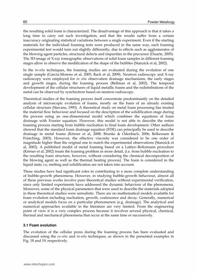
The foaming process can be divided into three stages: bubble nucleation, bubble growth and
foam collapse (Fig. 18b). Duarte and Banhart have done some pioneer research, in the
understanding of the mechanisms involved in the PM process, which contributed to the
significant advance of the state of the art (Duarte & Banhart, 2000), using ex-situ technique in
which the foaming process is interrupted by cooling at different foaming stages and the
resulting solid foam is characterized. Topics such as bubble nucleation, bubble growth and
foam stability were discussed. As a result of this research, it is concluded that the bubbles
nucleation occurs usually in the solid state, the pressure generated by the gas can deform
the metallic matrix, the process is governed by the principle of semisolid metal processing,
the bubble growth dynamics is controlled by the thermal decomposition of the blowing
agent and the metal melting.
00:00 00:05 00:10 00:45 00:50 00:55 01:000
10
20
30
40
50
60
EDC
B
A
Expan
sio
n (
mm
)
Time (hh:mm)
(a)
(b)
Fig. 18. (a) Expansion curve of precursor containing AA 6061 sample containing 0.6 wt. % TiH2 foamed in a pre-heated furnace at 800°C. (b) Morphology of the AA 6061 foams in different foaming stages (foam diameter 30 mm). The letters show at which expansion stage the sample was removed (see Fig. 15).
Foaming direction
Bubble nucleation Foam collapse Bubble growth
Coalescence effects
Drainage effects A B C D E
www.intechopen.com
Powder Metallurgy 62
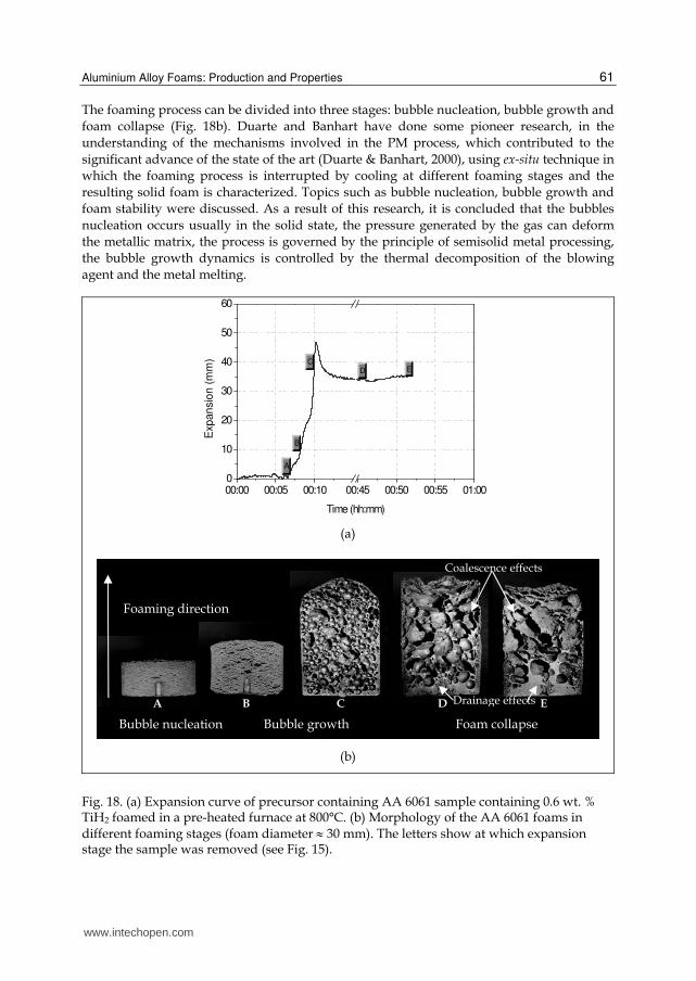
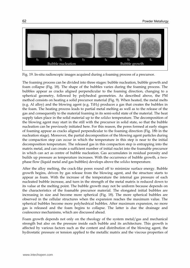
Fig. 19. In-situ radioscopic images acquired during a foaming process of a precursor.
The foaming process can be divided into three stages: bubble nucleation, bubble growth and foam collapse (Fig. 18). The shape of the bubbles varies during the foaming process. The bubbles appear as cracks aligned perpendicular to the foaming direction, changing to a spherical geometry, followed by polyhedral geometries. As described above, the PM method consists on heating a solid precursor material (Fig. 9). When heated, the metal melts (e.g. Al alloy) and the blowing agent (e.g. TiH2) produces a gas that creates the bubbles in the foam. The heating process leads to partial metal melting as well as to the release of the gas and consequently to the material foaming in its semi-solid state of the material. The heat supply takes place in the solid material up to the solidus temperature. The decomposition of the blowing agent may start in the still with the precursor in solid state, so that the bubble nucleation can be previously initiated here. For this reason, the pores formed at early stages of foaming appear as cracks aligned perpendicular to the foaming direction (Fig. 18b in the nucleation stage). Moreover, the partial decomposition of the blowing agent particles during the compaction step can occur in which the temperature in this step is near to the initial decomposition temperature. The released gas in this compaction step is entrapping into the matrix metal, and can create a sufficient number of initial nuclei into the foamable precursor in which can act as centre of bubble nucleation. Gas accumulates in residual porosity and builds up pressure as temperature increases. With the occurrence of bubble growth, a two-phase flow (liquid metal and gas bubbles) develops above the solidus temperature.
After the alloy melting, the crack-like pores round off to minimize surface energy. Bubble growth begins, driven by gas release from the blowing agent, and the structure starts to appear as foam. With the increase of the temperature the internal gas pressure of each nucleated bubble increase, and turn in the strength of the metal matrix is reduced down to its value at the melting point. The bubble growth may not be uniform because depends on the characteristics of the foamable precursor material. The elongated initial bubbles are increasing in size and become more spherical (Fig. 18). The more spherical bubbles are observed in the cellular structures when the expansion reaches the maximum value. The spherical bubbles become more polyhedrical bubbles. After maximum expansion, no more gas is released and the foam begins to collapse. The latter is due the drainage and coalescence mechanisms, which are discussed ahead.
Foam growth depends not only on the rheology of the system metal/gas and mechanical strength but also on the pressure inside each bubble and its architecture. This growth is affected by various factors such as the content and distribution of the blowing agent, the hydrostatic pressure or tension applied to the metallic matrix and the viscous properties of
t1 t2 t6 t5t4t3
Bubble nucleation Bubble growth
www.intechopen.com
Aluminium Alloy Foams: Production and Properties 63
the system (metal+gas). The metallic foaming rheology is not simple and its mechanical, thermal and chemical interaction leads to coupled problems of great complexity.
3.2 Foam: Collapse, stabilisation and solidification
The fundamental stability, collapse and solidification mechanisms during the foam formation have been investigated. These topics are the most controversial ones in the metal foam research. A better understanding of these mechanisms is required for an accurate control of the foam structures, such as cell size and porosity. Ex-situ and in-situ techniques have been used in this field. In-situ techniques have been used to measure the expansion, the density evolution and the effects of the drainage and coalescence. The effects of the thermal foaming cycle (heating rate, temperature and atmosphere) on the foam stability and foam collapse parameters have been also studied and observed (Banhart, 2006). PM foams belong to the class of transient (unstable) foams with lifetimes of seconds or to the permanent (metastable) foams with lifetimes of hours. The foamability is thought to result from the Gibbs–Marangoni effect where a membrane is stabilized during thinning due to liquid metal flow towards the weakened region, because of a local increase in surface tension. The flow is the response to a surface tension gradient. Due to viscous drag the flow can carry an appreciable amount of underlying liquid along with it so that it restores the thickness. In contrast to transient foams, the film thinning times in permanent foams are relatively short compared to the lifetime. The stability is controlled by the balance of interfacial forces. These forces equilibrate after drainage has been completed. The effect of temperature and gravity have been evaluated via observation of bubble size, ruptures of the bubbles, relative distribution of ruptures between bottom and top, draining and timing of draining, as well as the effect of temperature distribution.
Foam decays by combination of three phenomena – gas loss, drainage and coalescence (Duarte, 2005). Part of the gas is lost by diffusion from the outer surface to the surrounding. In the liquid state, loss is expected to rise due to a higher diffusivity than in its solid state. However, crack formation during expansion at the outer surface of precursors can also lead to gas losses. Moreover, bubble rupture at outer surface also results in sudden gas loss. The second and third way of gas loss are random events and not much effort was attributed to asses their contribution except for some qualitative statement. Drainage is one of the driving forces for the temporal instability of liquid foams, caused mainly by gravitational and capillary effects. The drainage and coalescence mechanisms can be observed using ex-situ techniques with the formation of a thick metal layer on the bottom of the solid foam and large pores, respectively. Foam shows a very complex rheological behaviour including the bubble deformation, rearrangement and avalanches processes.
Foam solidification is also an essential processing step of foam production. An uncontrolled solidification can create defects (e.g. cracks) in the cell wall of the foams (Duarte, 2005). So, this study helps to reduce the defects observed in final structures and thereby to improve the mechanical performance of the foam. The solidification by cooling of a foamed liquid metal is a “race against time", in as much as the relatively heavy liquid is prone to drainage, which rapidly reduces the foam density and hence provokes instability and collapse. The foamed liquid is immediately subjected to gravity-driven drainage of liquid, creating a vertical profile of density (or liquid fraction). At any point in the sample this adjustment must proceed until the freezing point is reached. Thus, at intermediate times, the sample
www.intechopen.com
Powder Metallurgy 64
consists of a solidified outer shell surrounding a draining liquid core. The competition between drainage and heat transfer, leading to solidification was studied by Mukherjee et al using X-ray radioscopy (Mukherjee et al, 2009). A hitherto unknown expansion stage was observed during solidification of Al-alloy foams. The phenomena that occur simultaneously while foam solidifies are associated to its volume change (Mukherjee et al, 2009). The extra expansion is observed and it is an anomalous behaviour since the foam is expected to contract during solidification. This extra expansion takes place whenever the combined volume gain rate is more than the combined volume loss rate. Moreover, it increases as the cooling rate decreases. Mukherjee reported that the slow cooling of foams can trigger extra expansion which in turn can induce defects in foam morphology. This is due to the extra expansion induced rupture during solidification of the metallic melt inside the cell wall.
4. Properties
The properties of the metal foams belong to a group of materials called cellular solids which are defined as having porosity >up to 0.7 (Gibson & Ashby, 1997). Natural foams are produced by plants and animals such as cork or bone. Man made foams can be manufactured from a variety of materials such as ceramics, polymers and metals. There are two categories of foams: open - and closed- cells. Here, it is presented a brief overview of the main properties of closed-cell Al-alloy foams obtained by the PM method.
Metal foams combine properties of cellular materials with those of metals. For this reason, metal foams are advantageous for lightweight constructions due to their high strength-to-weight ratio, in combination with structural and functional properties like crash energy absorption, sound and heat management (Asbhy et al, 2000; Degischer & Kriszt, 2002). Many metals and their alloys can be foamed. Among the metal foams, the Al-alloy ones are commercially the most exploited due to their low density, high ductility, high thermal conductivity, and metal competitive cost.
4.1 Structural properties
There are several structural parameters of these foams, such as number, size-pore distribution, average size, shape and geometry of the pores, thickness, intersections and defects in the cell-walls and thickness, defects and cracks of the external dense surface for describing the cellular architecture of the foams. The properties of these foams are influenced by these morphological features (Gibson &Ashby, 1997; Ramamurty & Paul, 2004; Campana et al, 2008).
Progress has been made in understanding the relationship between properties and morphology. Although this exact interrelationship is not yet sufficiently known, one usually assumes that the properties are improved when all the individual cells of a foam have similar size and a spherical shape. This has not really been verified experimentally. There is no doubt that the density of a metal foam and the matrix alloy properties influence the modulus and strength of the foam. All studies indicate that the real properties are inferior than the theoretically expected due to structural defects. This demands a better pore control and reduction in structural defects. Density variation and imperfections yield a large scatter of measured properties, which is detrimental for the metal foams reliability (Ramamurty & Paul, 2004). Wiggled or missing cell-walls reduce strength, and in turn, result in a reduced
www.intechopen.com
Aluminium Alloy Foams: Production and Properties 65
deformation energy absorbed under compression (Markaki & Clyne, 2001; Campana & Pilone, 2008). Mechanical studies demonstrate that selective deformation of the weakest region of the foam structure leads to crush-band formation (Duarte et al, 2009). Cell morphology and interconnection could also affect thermal and acoustic properties (Kolluri et al, 2008). It is widely accepted that foams with a uniform pore distribution and defects free, are desirable. This would make the properties more predictable. Only then, metal foams will be considered reliable materials for engineering purposes and will be able to compete with classical materials. Despite their quality improvement in the last 10 years the resulting metal foams still suffer from non-uniformities. Scientists aim to produce more regular structures with fewer defects in a more reproducible way which is the crucial challenge of the research in this field.
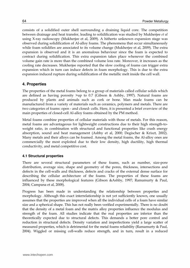
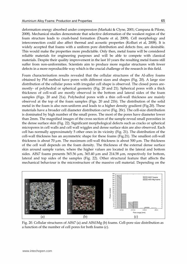
Foam characterisation results revealed that the cellular structures of the Al-alloy foams obtained by PM method have pores with different sizes and shapes (Fig. 20). A large size distribution of the cellular pores with irregular cell shape is observed. The closed pores are- mostly- of polyhedral or spherical geometry (Fig. 20 and 21). Spherical pores with a thick thickness of cell-wall are mostly observed in the bottom and lateral sides of the foam samples (Figs. 20 and 21a). Polyhedral pores with a thin cell-wall thickness are mainly observed at the top of the foam samples (Figs. 20 and 21b). The distribution of the solid metal in the foam is also non-uniform and leads to a higher density gradient (Fig.20). These materials have a broader cell diameter distribution curve (Fig. 20c). The cell-size distribution is dominated by high number of the small pores. The most of the pores have diameter lower than 2mm. The magnified images of the cross section of the sample reveal small porosities in the dense surface skin (Fig. 22). Significant morphological defects such as cracks or spherical micropores in cell walls and cell wall wiggles and dense surface skin are also observed. Each cell has normally approximately 5 other ones in its vicinity (Fig. 21). The distribution of the cell-wall thickness has an asymmetric shape for these foams (Fig.21). The smallest cell-wall
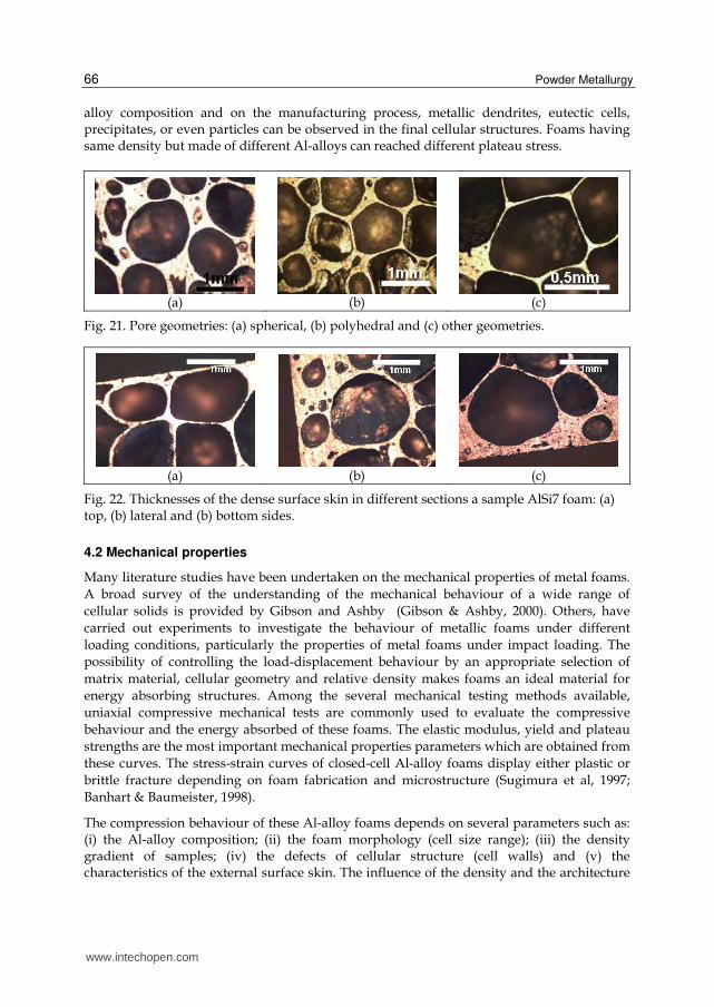
thickness is about 70 m. The maximum cell-wall thickness is about 500 m. The thickness of the cell wall depends on the foam density. The thickness of the external dense surface skin around sample varies, where the higher values are located in the lateral and bottom
sides. AlSi7 foams presents 565.56 m, 365.40 m and 214.58 m, respectively for bottom, lateral and top sides of the samples (Fig. 22). Other structural feature that affects the mechanical behaviour is the microstructure of the massive cell material. Depending on the
<2 mm 2-4 mm 4-6mm >6mm
0
25
50
75
100
125
150
175
200
225
250
275
300
325
350
375
400
425
Pore range [mm]
Pore
s n
um
ber
AlSi7-foams
AlSi1Mg-foams
(a) (b) (c)
Fig. 20. Cellular structures of AlSi7 (a) and AlSi1Mg (b) foams. Cell-pore size distribution as a function of the number of cell pores for both foams (c).
www.intechopen.com
Powder Metallurgy 66
alloy composition and on the manufacturing process, metallic dendrites, eutectic cells, precipitates, or even particles can be observed in the final cellular structures. Foams having same density but made of different Al-alloys can reached different plateau stress.
(a) (b) (c)
Fig. 21. Pore geometries: (a) spherical, (b) polyhedral and (c) other geometries.
(a) (b) (c)
Fig. 22. Thicknesses of the dense surface skin in different sections a sample AlSi7 foam: (a) top, (b) lateral and (b) bottom sides.
4.2 Mechanical properties
Many literature studies have been undertaken on the mechanical properties of metal foams.
A broad survey of the understanding of the mechanical behaviour of a wide range of
cellular solids is provided by Gibson and Ashby (Gibson & Ashby, 2000). Others, have
carried out experiments to investigate the behaviour of metallic foams under different
loading conditions, particularly the properties of metal foams under impact loading. The
possibility of controlling the load-displacement behaviour by an appropriate selection of
matrix material, cellular geometry and relative density makes foams an ideal material for
energy absorbing structures. Among the several mechanical testing methods available,
uniaxial compressive mechanical tests are commonly used to evaluate the compressive
behaviour and the energy absorbed of these foams. The elastic modulus, yield and plateau
strengths are the most important mechanical properties parameters which are obtained from
these curves. The stress-strain curves of closed-cell Al-alloy foams display either plastic or
brittle fracture depending on foam fabrication and microstructure (Sugimura et al, 1997;
Banhart & Baumeister, 1998).
The compression behaviour of these Al-alloy foams depends on several parameters such as: (i) the Al-alloy composition; (ii) the foam morphology (cell size range); (iii) the density gradient of samples; (iv) the defects of cellular structure (cell walls) and (v) the characteristics of the external surface skin. The influence of the density and the architecture
www.intechopen.com
Aluminium Alloy Foams: Production and Properties 67
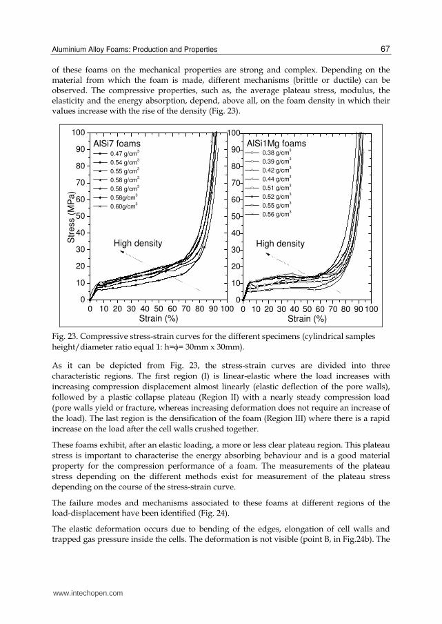
of these foams on the mechanical properties are strong and complex. Depending on the material from which the foam is made, different mechanisms (brittle or ductile) can be observed. The compressive properties, such as, the average plateau stress, modulus, the elasticity and the energy absorption, depend, above all, on the foam density in which their values increase with the rise of the density (Fig. 23).
0 10 20 30 40 50 60 70 80 90 1000
10
20
30
40
50
60
70
80
90
100
0 10 20 30 40 50 60 70 80 90 1000
10
20
30
40
50
60
70
80
90
100
AlSi7 foams 0.47 g/cm
3
0.54 g/cm3
0.55 g/cm3
0.58 g/cm3
0.58 g/cm3
0.58g/cm3
0.60g/cm3
Str
ess (
MP
a)
Strain (%)
High density High density
0.38 g/cm3
0.39 g/cm3
0.42 g/cm3
0.44 g/cm3
0.51 g/cm3
0.52 g/cm3
0.55 g/cm3
0.56 g/cm3
Strain (%)
AlSi1Mg foams
Fig. 23. Compressive stress-strain curves for the different specimens (cylindrical samples
height/diameter ratio equal 1: h== 30mm x 30mm).
As it can be depicted from Fig. 23, the stress-strain curves are divided into three
characteristic regions. The first region (I) is linear-elastic where the load increases with
increasing compression displacement almost linearly (elastic deflection of the pore walls),
followed by a plastic collapse plateau (Region II) with a nearly steady compression load
(pore walls yield or fracture, whereas increasing deformation does not require an increase of
the load). The last region is the densification of the foam (Region III) where there is a rapid
increase on the load after the cell walls crushed together.
These foams exhibit, after an elastic loading, a more or less clear plateau region. This plateau
stress is important to characterise the energy absorbing behaviour and is a good material
property for the compression performance of a foam. The measurements of the plateau
stress depending on the different methods exist for measurement of the plateau stress
depending on the course of the stress-strain curve.
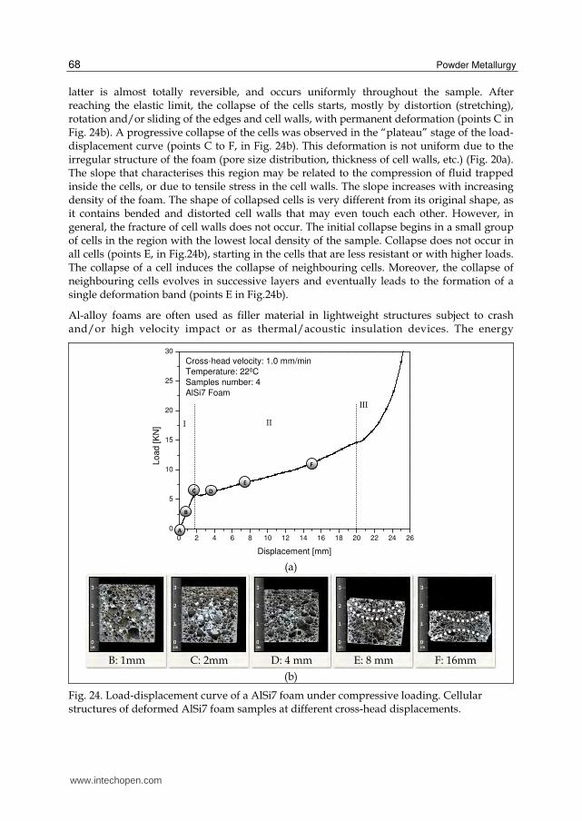
The failure modes and mechanisms associated to these foams at different regions of the load-displacement have been identified (Fig. 24).
The elastic deformation occurs due to bending of the edges, elongation of cell walls and trapped gas pressure inside the cells. The deformation is not visible (point B, in Fig.24b). The
www.intechopen.com
Powder Metallurgy 68
latter is almost totally reversible, and occurs uniformly throughout the sample. After reaching the elastic limit, the collapse of the cells starts, mostly by distortion (stretching), rotation and/or sliding of the edges and cell walls, with permanent deformation (points C in Fig. 24b). A progressive collapse of the cells was observed in the “plateau” stage of the load-displacement curve (points C to F, in Fig. 24b). This deformation is not uniform due to the irregular structure of the foam (pore size distribution, thickness of cell walls, etc.) (Fig. 20a). The slope that characterises this region may be related to the compression of fluid trapped inside the cells, or due to tensile stress in the cell walls. The slope increases with increasing density of the foam. The shape of collapsed cells is very different from its original shape, as it contains bended and distorted cell walls that may even touch each other. However, in general, the fracture of cell walls does not occur. The initial collapse begins in a small group of cells in the region with the lowest local density of the sample. Collapse does not occur in all cells (points E, in Fig.24b), starting in the cells that are less resistant or with higher loads. The collapse of a cell induces the collapse of neighbouring cells. Moreover, the collapse of neighbouring cells evolves in successive layers and eventually leads to the formation of a single deformation band (points E in Fig.24b).
Al-alloy foams are often used as filler material in lightweight structures subject to crash and/or high velocity impact or as thermal/acoustic insulation devices. The energy
(a)
(b)
Fig. 24. Load-displacement curve of a AlSi7 foam under compressive loading. Cellular structures of deformed AlSi7 foam samples at different cross-head displacements.
0 2 4 6 8 10 12 14 16 18 20 22 24 26
0
5
10
15
20
25
30
Cross-head velocity: 1.0 mm/min
Temperature: 22ºC
Samples number: 4
AlSi7 Foam
Load [K
N]
Displacement [mm]
A
B
C D
E
F
I II
III
B: 1mm C: 2mm D: 4 mm E: 8 mm F: 16mm
www.intechopen.com
Aluminium Alloy Foams: Production and Properties 69
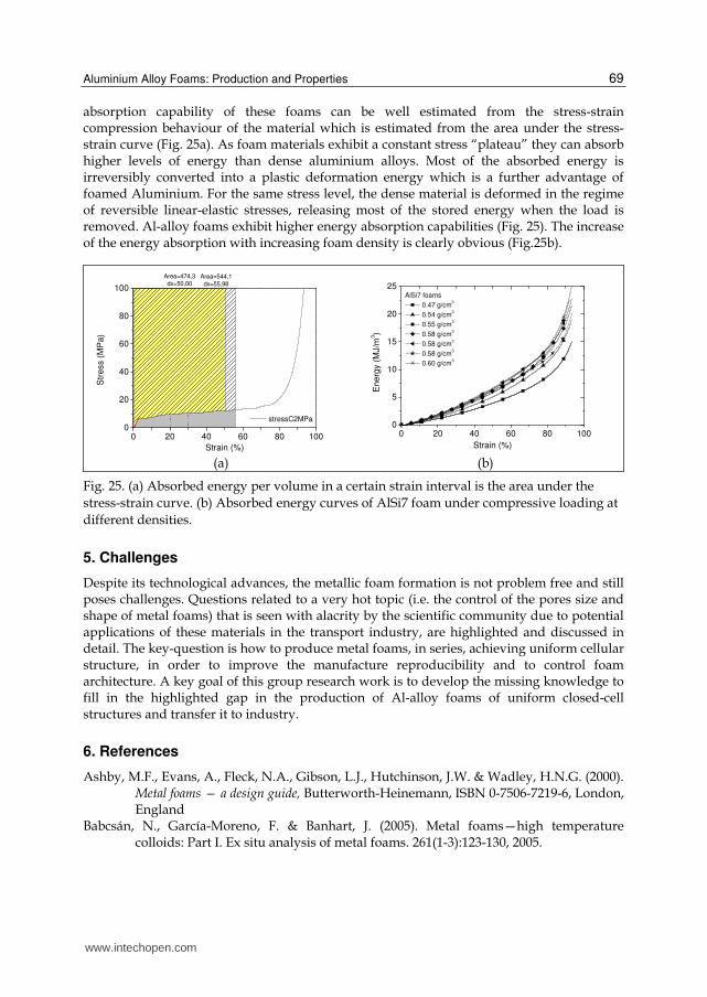
absorption capability of these foams can be well estimated from the stress-strain compression behaviour of the material which is estimated from the area under the stress-strain curve (Fig. 25a). As foam materials exhibit a constant stress “plateau” they can absorb higher levels of energy than dense aluminium alloys. Most of the absorbed energy is irreversibly converted into a plastic deformation energy which is a further advantage of foamed Aluminium. For the same stress level, the dense material is deformed in the regime of reversible linear-elastic stresses, releasing most of the stored energy when the load is removed. Al-alloy foams exhibit higher energy absorption capabilities (Fig. 25). The increase of the energy absorption with increasing foam density is clearly obvious (Fig.25b).
0 20 40 60 80 1000
20
40
60
80
100
Str
ess (
MP
a)
Strain (%)
stressC2MPa
Area=474,3dx=50,00
Area=544,1
dx=55,98
0 20 40 60 80 1000
5
10
15
20
25AlSi7 foams
0.47 g/cm3
0.54 g/cm3
0.55 g/cm3
0.58 g/cm3
0.58 g/cm3
0.58 g/cm3
0.60 g/cm3
Ene
rgy (
MJ/m
3)
Strain (%) (a) (b)
Fig. 25. (a) Absorbed energy per volume in a certain strain interval is the area under the
stress-strain curve. (b) Absorbed energy curves of AlSi7 foam under compressive loading at
different densities.
5. Challenges
Despite its technological advances, the metallic foam formation is not problem free and still poses challenges. Questions related to a very hot topic (i.e. the control of the pores size and shape of metal foams) that is seen with alacrity by the scientific community due to potential applications of these materials in the transport industry, are highlighted and discussed in detail. The key-question is how to produce metal foams, in series, achieving uniform cellular structure, in order to improve the manufacture reproducibility and to control foam architecture. A key goal of this group research work is to develop the missing knowledge to fill in the highlighted gap in the production of Al-alloy foams of uniform closed-cell structures and transfer it to industry.
6. References
Ashby, M.F., Evans, A., Fleck, N.A., Gibson, L.J., Hutchinson, J.W. & Wadley, H.N.G. (2000). Metal foams — a design guide, Butterworth-Heinemann, ISBN 0-7506-7219-6, London, England
Babcsán, N., García-Moreno, F. & Banhart, J. (2005). Metal foams—high temperature colloids: Part I. Ex situ analysis of metal foams. 261(1-3):123-130, 2005.
www.intechopen.com
Powder Metallurgy 70
Babcsán, N., García-Moreno, F. & Banhart, J. (2007). Metal foams - High temperature colloids. Part II: In-situ analysis of metal foams. Colloids and Surfaces A: Physicochemical and Engineering Aspects, Vol. 309, No. (1-3), pp. 254–263, ISSN 0927-7757
Banhart, J. (2001). Manufacture, characterisation and application ofcellular metals and metal foams Progress in Materials Science Vol. 46, No. (6), pp. 559–632, ISSN 0079-6425
Banhart, J. (2006), Metal foams: production and stability, Advanced Engineering Materials, Vol. 8, No. (9), pp. 781–794, ISSN 1438-1656
Banhart, J. (2008). Gold and gold alloy foams. Gold Bulletin, Vol. 41, No. (3), pp. 251-256, ISSN 0017-1557
Banhart, J. & Baumeister, J. (1998). Deformation characteristics of metal foams. Journal of Materials Science, Vol. 33, pp. 1431–1440, ISSN: 0022-2461
Baumgärtner, F., Duarte, I. & Banhart, J. (2000). Industrialisation of P/M foaming process. Advanced Engineering Materials, Vol.2, No.4, pp. 168-174, ISSN 1438-1656
Belkessam, O. & Fritsching U. (2003). Modelling and simulation of continuous metal foaming process. Modelling and Simulation in Materials Science and Engineering, Vol. 11, No.6, pp. 823–837, ISSN 0965-03932003.
Brunke, O. & Odenbach, S. (2006). In situ observation and numerical calculations of the evolution of metallic foams. Journal of Physics: Condensed Matter, Vol. 18, pp. 6493–6506, ISSN 0953-8984
Campana, F. & Pilone, D. (2008). Effect of wall microstructure and morphometric parameters on the crush behaviour of Al-alloy foams. Materials Science & Engineering A, Vol. 479, No. (1-2), pp. 58-64, ISSN 0921-5093
Cambronero, L.E.G., Ruiz-Roman, J.M., Corpas, F.A. & Ruiz Prieto, J.M. (2009). Manufacturing of Al–Mg–Si alloy foam using calcium carbonate as foaming agent. Journal of Materials Processing Technology, Vol. 209, pp. 1803–1809, ISSN 0924-0136
Degischer, H.P. & Kriszt, B. (Ed(s).) (2002). Handbook of Cellular Metals, Wiley-VCH, ISBN 3-527-30339-1, Weinheim
Duarte, I. & Banhart, J. (2000). A study of aluminium foam formation – kinetics and microstructure. Acta Materialia, Vol.48, No.9, pp. 2349-2362, ISSN 1359-6454
Duarte, I., Banhart, J. Ferreira & M. Santos. (2006) Foaming around fastening elements. Materials Science Forum, Vol. 514-516, pp. 712-717, ISSN 0255-5476
Duarte, I., Santos, M. & Vide, M. (2008). Processo contínuo de produção de peças e protótipos em espumas metálicas. Ingenium, II série, Março/Abril 2008, Vol. 104, pp. 78-80, ISSN 0870-5968I.
Duarte, I. (2005), Espumas Metálicas: Processos de fabrico, Caracterização e Simulação numérica. PhD thesis. FEUP- Faculty of Engineering of University of Porto, Porto.
Duarte, I., Teixeira-Dias, F., Graça, A. & Ferreira, AJM. (2010). Failure Modes and Influence of the Quasi-static Deformation Rate on the Mechanical Behavior of Sandwich Panels with Aluminum Foam Cores. Mechanics of Advanced Materials and Structures, Vol.17, No. (5), pp. 35-342, ISSN 1537-6494
Fang, J., Yang., Z., Zhang, H. &Ding, B. (2005). The coating process of silica film on TiH2 particles and gas release characteristic. Chemical Engineering Science, Vol. 60, pp. 845-850, ISSN 0009-2509
www.intechopen.com
Aluminium Alloy Foams: Production and Properties 71
Garcia-Moreno, F. , Babcsan, N. & Banhart, J. (2005). X-ray radioscopy of liquid metal foams: influence of heating profile, atmosphere and pressure. Colloids and Surfaces A: Physicochemical and Engineering Aspects, Vol. 263, pp. 290–294, ISSN 0927-7757
Gibson, L.J. & Ashby, M.F. (1997). Cellular solids – Structure and properties, Second Edition, Cambridge University Press, ISBN 0-521-49911-9, Cambridge, United Kindgom
Gokhale, A., Sahu, S.N., Kulkarni, V.K.W.R., Sudhakar, B., Rao & N. Ramachandra (2007) Effect of Titanium Hydride Powder Characteristics and Aluminium Alloy Composition on Foaming. High Temperature Materials and Processes. Vol. 26, No.4, pp. 247–256, ISSN 0334-6455
Haesche, M., Lehmhus,D., Weise, J., Wichmann, M. & Mocellin, I. C.M. (2010). Carbonates as Foaming Agent in Chip-based Aluminium Foam Precursor. Journal of Materials Science & Technology, Vol. 26, No. (9), pp. 845-850, ISSN 1005-0302
Helwig, H.-M., Garcia-Moreno, F. & Banhart, J. (2011). A study of Mg and Cu additions on the foaming behaviour of Al–Si alloys. Journal of Materials Science, Vol. 46, No. (15), pp. 5227-5236, ISSN 0022-2461.
Ibrahim, A., Körner, C. & Singer, R.F. (2008). The effect of TiH2 particle size on the morphology of Al-foam produced by PM process. Advanced Engineering Materials, Vol. 10, pp. 845–848, ISSN 1438-1656
Lehmhus, D. & Busse, M. (2004). Potential New Matrix Alloys for Production of PM Aluminium Foams. Advanced Engineering Materials, Vol. 6, pp. 391-396, ISSN 1438-1656.
Jiménez, C., García-Moreno, F., Mukherjee, M., Görke, O., Banhart, J. (2009). Improvement of aluminium foaming by powder consolidation under vacuum. Scripta Materialia, Vol.61, No.5, pp., 552–555, ISSN 1359-6462
Markaki, A.E. & Clyne, T.W. (2001). The effect of cell wall microstructure on the deformation and fracture of aluminum-based foams, Acta Materialia, Vol. 49, N.o 9, pp. 1677-1686, ISSN 1359-6454
Matijasevic, B. & Banhart, J. (2006). Improvement of aluminium foam technology by tailoring of blowing agent. Scripta Materialia, Vol. 54, No. (4), pp. 503-508, ISSN 1359-6462
Matijašević, B., Banhart, J., Fiechter, S., Görke, O., Wanderka, N. (2006), Modification of titanium hydride for improved aluminium foam manufacture, Acta Materialia, Vol. 54, N.o 7,pp. 1887–1900, ISSN 1359-6454
Miyoshi, T., Itoh, M., A. kiyama, S. & Kitahara, A. (2000). Alporas aluminum foam: production process, properties, and applications. Advanced Engineering Materials, Vol. 2, No. 4, pp. 179-183, ISSN 1438-1656
Mukherjee, M (2009). Evolution of metal foams during solidification, Technischen Universität Berlin
Proa-Flores, P.M. & Drew, RAL, (2008).Production of Aluminum Foams with Ni-coated TiH2 Powder. Advanced Engineering Materials, Vol. 10, No. (9), pp. 830-834, ISSN 1438-1656
Kennedy, A. R. (2002). Effect of compaction density on foamability of Al-TiH2 powder compacts. Powder Metallurgy, Vol. 45, No. (1), pp. 75-79, ISSN 0032-5899
Kennedy, A. R. (2004). Effect of foaming configuration on expansion. Journal of Materials Science. Vol. 39, pp. 1143-1145, ISSN 0022-2461
www.intechopen.com
Powder Metallurgy 72
Kitazono, K., Sato, E. & Kuribayashi, K. (2004), Novel manufacturing process of closed-cell aluminum foam by accumulative roll-bonding. Scripta Materialia, Vol. 50, No. (4), pp. 495–498, ISSN 1359-6462
Kolluri, M., Mukherjee, M., Garcia-Moreno, F., Banhart, J. & Ramamurty, U. (2008). Fatigue of a laterally constrained closed cell aluminum foam. Acta Materialia. Vol. 56, pp. 1114, ISSN 1359-6454
Körner, C., Thies, M. & Singer, R. F. (2002). Modeling of Metal Foaming with Lattice Boltzmann Automata. Advanced Engineering Materials, Vol. 4, N.o 10, pp. 765 - 769, ISSN 1438-1656
Körner, C., Arnold, & Singer, R. F. (2005). Metal foam stabilization by oxide network particles. Materials Science and Engineering A, Vol. 396, N.o (1-2), pp. 28–40, ISSN 0921-5093.
Körner, C. (2008). Foam formation mechanisms in particle suspensions applied to metal foams. Materials Science and Engineering A, Vol. 495, N.o (1-2), pp. 227-235, ISSN 0921-5093.
Rack, A., Helwig, H.-M., Bütow, A., Rueda, A., Matijasevic´-Lux, B., Helfen, L., Goebbels, J. & Banhart, J. (2009). Early pore formation in aluminium foams studied by synchrotron-based microtomography and 3-D image analysis. Acta Materialia 57(16): 4809–4821, 2009, ISSN 1359-6454
Ramamurty, U. & Paul, A. (2004). Variability in mechanical properties of a metal foam, Acta Materialia, Vol. 52, No. (4), pp. 869-876, ISSN 1359-6454
Sugimura, Y., Meyer, J., He, M.Y., Bart-Smith, H., Grenstedt, J. & Evans, A.G. (1997). On the mechanical performance of closed cell Al alloy foams. Acta Materialia, Vol. 45, No. (12), pp.5245-5259, ISSN 1359-6454
Stanzick, H., Helfen, L., Danikin, S. & Banhart, J. (2002). Material flow in metal foams studied by neutron radioscopy. Applied Physics A: Materials Science & Processing, Vol. 74, N.o (1), pp. 1118-1120, ISSN 0947-8396
Stavans, J. (1993). The evolution of cellular structures. Reports on Progress in Physics,Vol. 56, pp. 733-89, ISSN 0034-4885
Zeppelin, F., Hirscher, M., Stanzick, H. & Banhart, J (2003). Desorption of hydrogen from blowing agents used for foaming metals. Composite Science and Technology, Vol. 63, pp. 2293–2300, ISSN: 0266-3538
www.intechopen.com
Powder MetallurgyEdited by Dr. Katsuyoshi Kondoh
ISBN 978-953-51-0071-3Hard cover, 124 pagesPublisher InTechPublished online 09, March, 2012Published in print edition March, 2012
InTech EuropeUniversity Campus STeP Ri Slavka Krautzeka 83/A 51000 Rijeka, Croatia Phone: +385 (51) 770 447 Fax: +385 (51) 686 166www.intechopen.com
InTech ChinaUnit 405, Office Block, Hotel Equatorial Shanghai No.65, Yan An Road (West), Shanghai, 200040, China
Phone: +86-21-62489820 Fax: +86-21-62489821
From high-performance, economical and environmental points of view, Powder metallurgy process showsremarkable advantages in production of parts and components due to their special compositions by elementalmixing and 3-dimensional near net shape forming methods. Powder metallurgy process can be applied to notonly metal materials but also ceramics and organic materials, which both are employed as structural andelectrical products. Author contributions to Powder metallurgy present excellent and significantly importantresearch topics to evaluate various properties and performance of P/M materials for applying these materialsas actual components. In particular, the life estimation of P/M ferrous materials by sliding contact fatigue testand tribological performance evaluation of P/M semi-metallic materials are focused and introduced in thisbook.
How to referenceIn order to correctly reference this scholarly work, feel free to copy and paste the following:
Isabel Duarte and Mónica Oliveira (2012). Aluminium Alloy Foams: Production and Properties, PowderMetallurgy, Dr. Katsuyoshi Kondoh (Ed.), ISBN: 978-953-51-0071-3, InTech, Available from:http://www.intechopen.com/books/powder-metallurgy/aluminium-alloys-foams-production-and-properties

© 2012 The Author(s). Licensee IntechOpen. This is an open access articledistributed under the terms of the Creative Commons Attribution 3.0License, which permits unrestricted use, distribution, and reproduction inany medium, provided the original work is properly cited.