Alumina ultrafiltration membranes derived from carboxylate–alumoxane nanoparticles
10
Journal of Membrane Science 193 (2001) 175–184 Alumina ultrafiltration membranes derived from carboxylate–alumoxane nanoparticles Christopher D. Jones a , Maria Fidalgo b , Mark R. Wiesner b , Andrew R. Barron a,c,∗ a Department of Chemistry and Center for Nanoscale Science and Technology, Rice University, Houston, TX 77005, USA b Department of Environmental Science and Engineering, Rice University, Houston, TX 77005, USA c Department of Mechanical Engineering and Materials Science, Rice University, Houston, TX 77005, USA Received 2 January 2001; received in revised form 3 May 2001; accepted 4 May 2001 Abstract The fabrication of asymmetric alumina ultrafiltration membranes using acetic acid surface stabilized alumina nanoparticles (A-alumoxanes) has been investigated. Contacting -alumina supports with an aqueous solution of A-alumoxane (after firing to 1000 ◦ C) yields a defect free alumina membrane with a thickness of ca. 2 m. The alumoxane-derived membranes have a molec- ular weight cut-off in the range of 35,000–44,000 g mol −1 , high porosity, and a permeability that is comparable to or greater than that of commercially available alumina membranes. SEM and AFM show that the surface of the alumoxane-derived membranes is quite smooth and contact angles show that the membrane is hydrophillic. A comparison with commercial alumina and poly- mer membranes, as well as those derived from sol–gel methods is presented. © 2001 Elsevier Science B.V. All rights reserved. Keywords: Ceramic; Alumoxane; Alumina; Membrane; Nanoparticle; Ultrafiltration 1. Introduction Membrane technologies play an increasingly important role in pollution prevention, resource re- covery and waste treatment activities [1]. Due in large part to cost considerations, polymeric mem- branes dominate these applications [2], however, the use of polymeric membranes in separations involving aggressive materials such as many organic solvents, acids, bases and oxidants is often limited by the toler- ance of the polymeric material to extreme conditions [3,4]. Ceramic membranes are noted for their excel- lent mechanical strength and tolerance to solvents, as well as pH, oxidation, and temperature extremes [5]. ∗ Corresponding author. Tel.: +1-713-348-5610; fax: +1-713-348-5619; URL: www.rice.edu/barron. E-mail address: [email protected] (A.R. Barron). An ideal ceramic membrane must be highly se- lective, permeable and durable [6,7]. For aqueous applications, or aqueous/organic separations it is de- sirable for the ceramic to be hydrophilic to maximize flow and minimize fouling. The membrane selectivity is primarily dependent upon the pore size distribu- tion; the narrower the pores size distribution, the more selective the membrane. Mechanical integrity is enhanced in such applications by slip-casting a rela- tively thin selective membrane onto a thicker, more permeable support yielding an asymmetric membrane. The sintering of ceramic particles is perhaps the simplest approach to forming a porous ceramic filter, however, the sintering of bulk ceramics is a very en- ergy expensive process due to the high temperatures required. The pore size is controlled by the starting particle size, sintering time and temperature [8–10]. Due to the large size of the starting particles, it is 0376-7388/01/$ – see front matter © 2001 Elsevier Science B.V. All rights reserved. PII:S0376-7388(01)00490-2
-
Upload
christopher-d-jones -
Category
Documents
-
view
215 -
download
3
Transcript of Alumina ultrafiltration membranes derived from carboxylate–alumoxane nanoparticles
Journal of Membrane Science 193 (2001) 175–184
Alumina ultrafiltration membranes derived fromcarboxylate–alumoxane nanoparticles
Christopher D. Jones a, Maria Fidalgo b, Mark R. Wiesner b, Andrew R. Barron a,c,∗a Department of Chemistry and Center for Nanoscale Science and Technology, Rice University, Houston, TX 77005, USA
b Department of Environmental Science and Engineering, Rice University, Houston, TX 77005, USAc Department of Mechanical Engineering and Materials Science, Rice University, Houston, TX 77005, USA
Received 2 January 2001; received in revised form 3 May 2001; accepted 4 May 2001
Abstract
The fabrication of asymmetric alumina ultrafiltration membranes using acetic acid surface stabilized alumina nanoparticles(A-alumoxanes) has been investigated. Contacting �-alumina supports with an aqueous solution of A-alumoxane (after firing to1000◦C) yields a defect free alumina membrane with a thickness of ca. 2 �m. The alumoxane-derived membranes have a molec-ular weight cut-off in the range of 35,000–44,000 g mol−1, high porosity, and a permeability that is comparable to or greater thanthat of commercially available alumina membranes. SEM and AFM show that the surface of the alumoxane-derived membranesis quite smooth and contact angles show that the membrane is hydrophillic. A comparison with commercial alumina and poly-mer membranes, as well as those derived from sol–gel methods is presented. © 2001 Elsevier Science B.V. All rights reserved.
Keywords: Ceramic; Alumoxane; Alumina; Membrane; Nanoparticle; Ultrafiltration
1. Introduction
Membrane technologies play an increasinglyimportant role in pollution prevention, resource re-covery and waste treatment activities [1]. Due inlarge part to cost considerations, polymeric mem-branes dominate these applications [2], however, theuse of polymeric membranes in separations involvingaggressive materials such as many organic solvents,acids, bases and oxidants is often limited by the toler-ance of the polymeric material to extreme conditions[3,4]. Ceramic membranes are noted for their excel-lent mechanical strength and tolerance to solvents, aswell as pH, oxidation, and temperature extremes [5].
∗ Corresponding author. Tel.: +1-713-348-5610;fax: +1-713-348-5619; URL: www.rice.edu/barron.E-mail address: [email protected] (A.R. Barron).
An ideal ceramic membrane must be highly se-lective, permeable and durable [6,7]. For aqueousapplications, or aqueous/organic separations it is de-sirable for the ceramic to be hydrophilic to maximizeflow and minimize fouling. The membrane selectivityis primarily dependent upon the pore size distribu-tion; the narrower the pores size distribution, themore selective the membrane. Mechanical integrity isenhanced in such applications by slip-casting a rela-tively thin selective membrane onto a thicker, morepermeable support yielding an asymmetric membrane.
The sintering of ceramic particles is perhaps thesimplest approach to forming a porous ceramic filter,however, the sintering of bulk ceramics is a very en-ergy expensive process due to the high temperaturesrequired. The pore size is controlled by the startingparticle size, sintering time and temperature [8–10].Due to the large size of the starting particles, it is
0376-7388/01/$ – see front matter © 2001 Elsevier Science B.V. All rights reserved.PII: S0376 -7388 (01 )00490 -2
176 C.D. Jones et al. / Journal of Membrane Science 193 (2001) 175–184
extremely difficult, and not very efficient, to makeultrafiltration filters by this method because of graingrowth during sintering, resulting in low porosity andlarge pores [11]. This method is generally used toproduce alumina microfiltration filters, which containlarger pores and supports for ultrafiltration mem-branes, which contain smaller pores [12,13]. Of thepresent technologies, sol–gel is the best method formaking ceramic ultrafiltration membranes. However,the pore size is generally limited to the sizes of theceramic precursor particles prior to sintering. Forsol–gels, the particle size distribution is difficult tocontrol, and they must be used immediately afterpreparation to avoid aggregation or precipitation.
We have previously reported that aluminum-oxidenanoparticles may be prepared by the reaction of themineral boehmite with carboxylic acids [14,15]. Thesenanoparticles can be used as precursors for ceramicmembranes as an alternative to the conventional sol–gel techniques. The identity of the carboxylic acid app-ears to control the size of the nanoparticles (5–80 nm).These nanoparticles, “carboxylate–alumoxanes”, arereadily processed to alumina bodies and coatings[16,15]. The thermolysis of carboxylate–alumoxanesyield alumina membranes that exhibit narrow poresize distributions with pore sizes in the ultrafiltrationrange [17]. The pore size and porosity are depen-dent on the choice of carboxylate periphery and thesintering temperature [18].
In this paper, we present results from experimentsin which alumoxane nanoparticles were cast onporous ceramic supports to yield asymmetric aluminamembranes.
2. Experimental procedure
2.1. Materials
Acetate-alumoxane (A-alumoxane) was preparedby previously published methods [15]. Aqueous so-lutions of A-alumoxane were degassed prior to use.RefractronTM �-alumina supports were obtained fromthe Refractron Technologies Corp. (Newark, NJ) andwere heated to 600◦C prior to use to remove surfacegrease. For comparison, WhatmanTM (AnodiscTM)and CorningTM (NucleoporeTM) filters were used asreceived.
2.2. Fabrication of asymmetric membranes
One face of a RefractronTM �-alumina support wasbrought into contact with an A-alumoxane solution(0.5–10 wt.%) so that only the surface touched thesolution for approximately 2–5 s. Penetration of theA-alumoxane solution into the voids of the support oc-curs by capillary action. The support was then shakento remove any excess solution, and dried at roomtemperature for 2 h. The coated support was heated to600◦C for 4 h, held for 3 h and then, heated to 1000◦Cfor 3 h. Multiple coatings were obtained by treat-ing a previously coated filter (1 wt.% A-alumoxane)fired to 1000◦C, with a 1 wt.% aqueous solution ofA-alumoxane followed by firing to 1000◦C. X-raydiffraction analysis revealed the resultant membraneto be �-Al2O3 (after heating to 600◦C) or �-Al2O3(with traces of �-Al2O3 after sintering to 1000◦C).
Porosity, surface area, pore volume, and pore sizedistribution measurements were made on a symmetricmembranes prepared by pouring a 1 wt.% solution ofA-alumoxane into a TeflonTM drying mold. The solu-tion was dried at room temperature, yielding a greenbody of ca. 1 mm in thickness. The green body wasthen heated under identical conditions to that used forthe asymmetric membranes.
2.3. Characterization methods
Scanning electron microscopy (SEM) studies wereperformed on a Phillips XL-30 ESEM scanning mi-croscope. The samples were attached to a metal mountusing carbon tape. Due to the insulating nature of thematerials, a thin layer of gold was applied as a coatingto provide a conducting surface.
AFM images of samples were obtained using aNanoscope IIIa Scanning Probe Microscope (DigitalInstruments, Santa Barbara, CA) in tapping mode.FESP tips were used with a pyramidal shape andend radius of 5–10 nm (Digital Instruments). Sampleswere attached to 15 mm magnetic specimen diskswith carbon tape. Roughness and cross-section analy-sis were determined by the accompanying NanoscopeIIIa software.
Contact angles were measured using a Goniome-ter. Surface charge was determined by measuringelectrophoretic mobility with a Zeta Meter 3.0 (Zeta-Meter Inc.).
C.D. Jones et al. / Journal of Membrane Science 193 (2001) 175–184 177
Porosity, surface area, pore volume, and poresize distributions were obtained using nitrogen ad-sorption/desorption techniques using a CoulterTM
SA3100TM. Helium was used to determine the freespace in the sample tube and nitrogen as the ab-sorbate gas. All samples were outgassed at 300◦Cfor 2 h under a stream of dry nitrogen using aCoulterTM SAPrepTM. Calculations were based onthe cross-sectional area of nitrogen using the valueof 0.162 nm2. Surface area was calculated using theBET (Brunauer, Emmett and Teller) equation withfive data points. Pore size distributions were deter-mined using the BJH (Barrett, Joyner, and Halenda)technique using 65 data points from the nitrogen ad-sorption isotherm [19]. Pore volume calculation wasperformed at a relative pressure of 0.9814.
Pure water flux was measured on both thecarboxylate–alumoxane-derived filters and commer-cial samples (AnodiscTM and NucleoporeTM). Sam-ples were glued using silicone adhesive to plasticrings to adapt their size to the filtration cell. Theeffective filtration area was 1.61 × 10⁻³ m2 for allsamples. The experiment was conducted using a deadend filtration cell (Amicon, Model 8200). A zero airtank was connected to the cell for pressure, and aregulator was used to maintain a constant pressure of10 psi. Permeate was collected at atmospheric pres-sure, so that the pressure at the end of the regulatorwas equal to the transmembrane pressure. Permeatevolume was measured over time to calculate flux.
Molecular weight cut-off (MWCO) experimentwere performed following the American Society forTesting and Materials (ASTM) Publication E 1343-90.The concentration, molecular weight characteristicsof the dextran used in this study and the solute diam-eters are summarized in Table 1. Sodium azide (99%,Aldrich) was added at a concentration of 0.05 wt.%to prevent bacterial growth and NaCl (0.05 M) was
Table 1Molecular weight (Mw) and solute (ds) diameters of dextran inaqueous solution used to calculate the MWCO
Dextran Concentra-tion (wt.%)
Average Mw
(g mol−1)ds (nm)
T-10 0.25 10500 1.8–3T-40 0.10 37500 4–6T-70 0.10 69800 6–9T-500 0.20 413000 >15
added to control the ionic strength. Ultra-pure waterwas used in all the experiments (10 M�). Sampleswere prepared identical to those for the permeabilitymeasurements and placed in a stirred ultrafiltrationcell (Amicon, Model 8200). The cell was modified toallow for re-circulation of the feed. A hole was drilledin the top of the cell to insert a 1/8 in. stainless steeltube, used as inlet for the feed. The existing fittingwas used as exit of flow. The feed was pumped at arate of 100–110 ml min−1. A valve and pressure gageat the flow exit of the cell allowed for transmembranepressure control. The pressure in the regulator was setat 7 ± 0.5 psi. The permeate samples were collectedafter allowing the system to run for 30 min. Thevelocity of the flow across the membrane was keptbelow 0.15 ml min−1 to avoid deformation effects ofthe macromolecules with a peristaltic pump at thepermeate line. A sample of the feed was taken at theend of each filtration.
Feed and permeate samples were analyzed by gelpermeation chromatography (GPC). A HPLC system(Waters 717+ Autosampler, Waters 600E SystemController) was used with a GPC column (TosoHaasG4000PWXL). Calibration curves (molecular weightversus elution time) were obtained running each dex-tran fraction separately. The peak was assumed tocorrespond to the average molecular weight givenby the manufacturer. The elute was collected everymilliliter with a fraction collector (Waters). The con-centration of solute in each fraction was determinedmeasuring organic carbon concentration, using a TotalOrganic Carbon Analyzer (Shimatzu, TOC 5050A).Three HPLC runs were performed with each sampleand each fraction was analyzed three times by theTOC analyzer.
3. Results and discussion
Commercially available �-alumina (RefractronTechnologies Corp.) porous disks were used as sup-ports for casting the alumoxane-derived membranes.The surface of the RefractronTM �-alumina supportis quite rough and there appears to be a significantnumber of void spaces on the top surface of the sup-port (Fig. 1a). A closer view of the support (Fig. 1b)shows that the support is composed of alumina parti-cles sintered together with particle sizes ranging from
178 C.D. Jones et al. / Journal of Membrane Science 193 (2001) 175–184
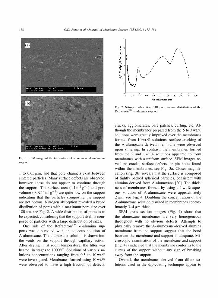
Fig. 1. SEM image of the top surface of a commercial �-aluminasupport.
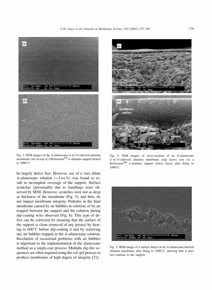
1 to 0.05 �m, and that pore channels exist betweensintered particles. Many surface defects are observed,however, these do not appear to continue throughthe support. The surface area (4.1 m2 g−1) and porevolume (0.0244 ml g−1) are quite low on the supportindicating that the particles composing the supportare not porous. Nitrogen absorption revealed a broaddistribution of pores with a maximum pore size over180 nm, see Fig. 2. A wide distribution of pores is tobe expected, considering that the support itself is com-posed of particles with a large distribution of sizes.
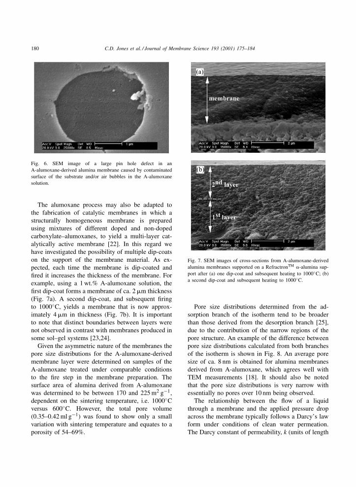
One side of the RefractronTM �-alumina sup-ports was dip-coated with an aqueous solution ofA-alumoxane. The alumoxane solution is drawn intothe voids on the support through capillary action.After drying in at room temperature, the filter washeated, in stages to 1000◦C. Solutions of various so-lutions concentrations ranging from 0.5 to 10 wt.%were investigated. Membranes formed using 10 wt.%were observed to have a high fraction of defects;
Fig. 2. Nitrogen adsorption BJH pore volume distribution of theRefractronTM �-alumina support.
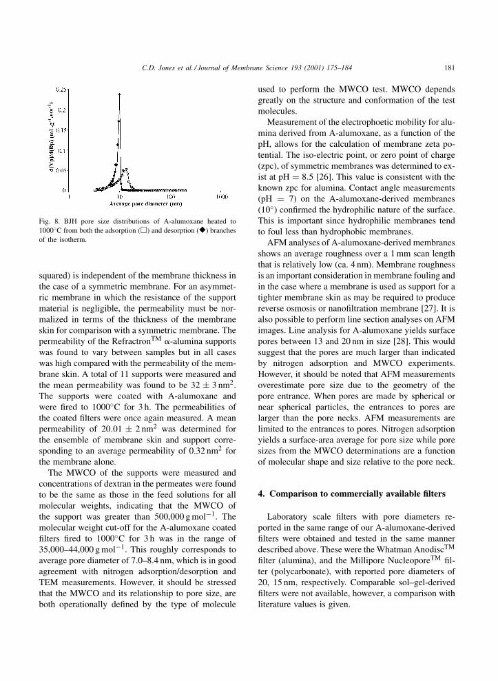
cracks, agglomerates, bare patches, curling, etc. Al-though the membranes prepared from the 5 to 3 wt.%solutions were greatly improved over the membranesformed from 10 wt.% solutions, surface cracking ofthe A-alumoxane-derived membrane were observedupon sintering. In contrast, the membranes formedfrom the 2 and 1 wt.% solutions appeared to formmembranes with a uniform surface. SEM images re-veal no cracks, surface defects, or pin holes foundwithin the membranes, see Fig. 3a. Closer magnifi-cation (Fig. 3b) reveals that the surface is composedof tightly packed spherical particles, consistent withalumina derived from A-alumoxane [20]. The thick-ness of membranes formed by using a 1 wt.% aque-ous solution of A-alumoxane were approximately2 �m, see Fig. 4. Doubling the concentration of theA-alumoxane solution resulted in membranes approx-imately 3–4 �m thick.
SEM cross section images (Fig. 4) show thatthe alumoxane membranes are very homogeneousthroughout with no obvious defects. Attempts tophysically remove the A-alumoxane-derived aluminamembrane from the support suggest that the bondbetween the membrane and support is adequate. Mi-croscopic examination of the membrane and support(Fig. 4a) indicated that the membrane conforms to thecurves of the support without any sign of breakingaway from the support.
Overall, the membranes derived from dilute so-lutions used in the dip-coating technique appear to
C.D. Jones et al. / Journal of Membrane Science 193 (2001) 175–184 179
Fig. 3. SEM images of the A-alumoxane (1 wt.%)-derived aluminamembrane cast on top of a RefractronTM �-alumina support heatedto 1000◦C.
be largely defect free. However, use of a very diluteA-alumoxane solution (<1 wt.%) was found to re-sult in incomplete coverage of the support. Surfacescratches (presumably due to handling) were ob-served by SEM. However, scratches were not as deepas thickness of the membrane (Fig. 5), and thus, donot impact membrane integrity. Pinholes in the finalmembrane caused by air bubbles in solution, or by airtrapped between the support and the solution duringdip-coating were observed (Fig. 6). This type of de-fect can be corrected by ensuring that the surface ofthe support is clean (removal of any grease) by heat-ing to 600◦C before dip-coating it and by removingany air bubbles trapped in the A-alumoxane solution.Resolution of occasional problems with air bubblesis important to the implementation of the alumoxanemethod as a single-cast process. Multiple dip-fire se-quences are often required using the sol–gel process toproduce membranes of high degree of integrity [21].
Fig. 4. SEM images of cross-sections of an A-alumoxane(1 wt.%)-derived alumina membrane (top layer) cast on aRefractronTM �-alumina support (lower layer) after firing to1000◦C.
Fig. 5. SEM image of a surface defect in an A-alumoxane-derivedalumina membrane after firing to 1000◦C, showing that it doesnot continue to the support.
180 C.D. Jones et al. / Journal of Membrane Science 193 (2001) 175–184
Fig. 6. SEM image of a large pin hole defect in anA-alumoxane-derived alumina membrane caused by contaminatedsurface of the substrate and/or air bubbles in the A-alumoxanesolution.
The alumoxane process may also be adapted tothe fabrication of catalytic membranes in which astructurally homogeneous membrane is preparedusing mixtures of different doped and non-dopedcarboxylate–alumoxanes, to yield a multi-layer cat-alytically active membrane [22]. In this regard wehave investigated the possibility of multiple dip-coatson the support of the membrane material. As ex-pected, each time the membrane is dip-coated andfired it increases the thickness of the membrane. Forexample, using a 1 wt.% A-alumoxane solution, thefirst dip-coat forms a membrane of ca. 2 �m thickness(Fig. 7a). A second dip-coat, and subsequent firingto 1000◦C, yields a membrane that is now approx-imately 4 �m in thickness (Fig. 7b). It is importantto note that distinct boundaries between layers werenot observed in contrast with membranes produced insome sol–gel systems [23,24].
Given the asymmetric nature of the membranes thepore size distributions for the A-alumoxane-derivedmembrane layer were determined on samples of theA-alumoxane treated under comparable conditionsto the fire step in the membrane preparation. Thesurface area of alumina derived from A-alumoxanewas determined to be between 170 and 225 m2 g−1,dependent on the sintering temperature, i.e. 1000◦Cversus 600◦C. However, the total pore volume(0.35–0.42 ml g−1) was found to show only a smallvariation with sintering temperature and equates to aporosity of 54–69%.
Fig. 7. SEM images of cross-sections from A-alumoxane-derivedalumina membranes supported on a RefractronTM �-alumina sup-port after (a) one dip-coat and subsequent heating to 1000◦C; (b)a second dip-coat and subsequent heating to 1000◦C.
Pore size distributions determined from the ad-sorption branch of the isotherm tend to be broaderthan those derived from the desorption branch [25],due to the contribution of the narrow regions of thepore structure. An example of the difference betweenpore size distributions calculated from both branchesof the isotherm is shown in Fig. 8. An average poresize of ca. 8 nm is obtained for alumina membranesderived from A-alumoxane, which agrees well withTEM measurements [18]. It should also be notedthat the pore size distributions is very narrow withessentially no pores over 10 nm being observed.
The relationship between the flow of a liquidthrough a membrane and the applied pressure dropacross the membrane typically follows a Darcy’s lawform under conditions of clean water permeation.The Darcy constant of permeability, k (units of length
C.D. Jones et al. / Journal of Membrane Science 193 (2001) 175–184 181
Fig. 8. BJH pore size distributions of A-alumoxane heated to1000◦C from both the adsorption (�) and desorption (�) branchesof the isotherm.
squared) is independent of the membrane thickness inthe case of a symmetric membrane. For an asymmet-ric membrane in which the resistance of the supportmaterial is negligible, the permeability must be nor-malized in terms of the thickness of the membraneskin for comparison with a symmetric membrane. Thepermeability of the RefractronTM �-alumina supportswas found to vary between samples but in all caseswas high compared with the permeability of the mem-brane skin. A total of 11 supports were measured andthe mean permeability was found to be 32 ± 3 nm2.The supports were coated with A-alumoxane andwere fired to 1000◦C for 3 h. The permeabilities ofthe coated filters were once again measured. A meanpermeability of 20.01 ± 2 nm2 was determined forthe ensemble of membrane skin and support corre-sponding to an average permeability of 0.32 nm2 forthe membrane alone.
The MWCO of the supports were measured andconcentrations of dextran in the permeates were foundto be the same as those in the feed solutions for allmolecular weights, indicating that the MWCO ofthe support was greater than 500,000 g mol−1. Themolecular weight cut-off for the A-alumoxane coatedfilters fired to 1000◦C for 3 h was in the range of35,000–44,000 g mol−1. This roughly corresponds toaverage pore diameter of 7.0–8.4 nm, which is in goodagreement with nitrogen adsorption/desorption andTEM measurements. However, it should be stressedthat the MWCO and its relationship to pore size, areboth operationally defined by the type of molecule
used to perform the MWCO test. MWCO dependsgreatly on the structure and conformation of the testmolecules.
Measurement of the electrophoetic mobility for alu-mina derived from A-alumoxane, as a function of thepH, allows for the calculation of membrane zeta po-tential. The iso-electric point, or zero point of charge(zpc), of symmetric membranes was determined to ex-ist at pH = 8.5 [26]. This value is consistent with theknown zpc for alumina. Contact angle measurements(pH = 7) on the A-alumoxane-derived membranes(10◦) confirmed the hydrophilic nature of the surface.This is important since hydrophilic membranes tendto foul less than hydrophobic membranes.
AFM analyses of A-alumoxane-derived membranesshows an average roughness over a 1 mm scan lengththat is relatively low (ca. 4 nm). Membrane roughnessis an important consideration in membrane fouling andin the case where a membrane is used as support for atighter membrane skin as may be required to producereverse osmosis or nanofiltration membrane [27]. It isalso possible to perform line section analyses on AFMimages. Line analysis for A-alumoxane yields surfacepores between 13 and 20 nm in size [28]. This wouldsuggest that the pores are much larger than indicatedby nitrogen adsorption and MWCO experiments.However, it should be noted that AFM measurementsoverestimate pore size due to the geometry of thepore entrance. When pores are made by spherical ornear spherical particles, the entrances to pores arelarger than the pore necks. AFM measurements arelimited to the entrances to pores. Nitrogen adsorptionyields a surface-area average for pore size while poresizes from the MWCO determinations are a functionof molecular shape and size relative to the pore neck.
4. Comparison to commercially available filters
Laboratory scale filters with pore diameters re-ported in the same range of our A-alumoxane-derivedfilters were obtained and tested in the same mannerdescribed above. These were the Whatman AnodiscTM
filter (alumina), and the Millipore NucleoporeTM fil-ter (polycarbonate), with reported pore diameters of20, 15 nm, respectively. Comparable sol–gel-derivedfilters were not available, however, a comparison withliterature values is given.

182 C.D. Jones et al. / Journal of Membrane Science 193 (2001) 175–184
Table 2Comparison of commercially available ultrafiltration filters
Alumoxane Whatman AnodiscTM (20 nm)a Millipore NucleoporeTM (15 nm)a
Surface area (m2 g−1) 100–225 n/a 1.5Porosity (%) 54–69 25–30 <15Pore size (nm) 8–20 20 15Permeability (nm2) 20 (0.32)b 3 0.05MWCO (103 Da) 11–44c (100%) 20d (0%) 20d (44%)AFM estimated pore size (nm) 16–23 30 27Contact angle (◦) 10 10 30Roughness (nm)e 4–6 6.5 2.8Maximum operating temperature (◦C) 1000f <400 140
a Nominal pore size reported by manufacturer.b Value for ensemble of 2 �m membrane and porous support. Intrinsic permeability of alumoxane-derived membrane given in parentheses.c Lower values obtained for membranes fired to 600◦C.d Based on PEG, percent retention (R) in parenthesis.e 1 �m scan length.f Pore size decreases due to sintering and grain growth.
The AnodiscTM filter is formed from the anodicoxidation of aluminum metal, resulting in a filtermade of amorphous alumina. The pores grow so thattheir diameter is proportional to the applied voltage,while current governs film thickness [4]. The bulkporous layer contains pores approximately 100 nm,while the membrane contains pores approximately20 nm in diameter. The NucleoporeTM filter is madefrom dense polycarbonate that has been exposed tohigh energy particle radiation applied perpendicularto the film [29]. A summary of characteristics for theA-alumoxane alumina membranes, the AnodiscTM
filter and NucleoporeTM filter is given in Table 2.Despite a smaller or comparable pore size, the
A-alumoxane-derived alumina membranes have amuch higher surface area and porosity than theAnodiscTM and the NucleoporeTM membranes (Ta-ble 2). The A-alumoxane-derived filters have smallerpore sizes than either of the other filters tested. Allthree filters exhibited a narrow pore size distributionand similar dimension of roughness and contact angle.An important advantage of the A-alumoxane-derivedalumina membranes can be operated at temperatureshigher than the alumina AnodiscTM (maximum tem-perature 400◦C).
Alumina sol–gel-derived membranes are presentlythe most accepted route to making alumina ultra-filtration filters. Lennears et al. [30], Lennears andBurggraaf [31–33], first developed the technique ofusing sol–gel processes to make alumina ultrafiltration
membranes. These filters, along with the vast majorityof those reported in the literature [34–37], were madeby the controlled hydrolysis of aluminum alkoxidesto form alumina. Mixed metal membranes have alsobeen reported by similar methods [38,39]. The prepa-ration techniques used by various researchers vary thedrying or sintering conditions which results to smallchanges in porosity or pore size.
The pore sizes for sol–gel membranes are depen-dent on the preparation and firing temperature. Thepore sizes at temperatures below 900◦C all had modaldiameters below 9 nm, while those fired to 1000◦Cshowed an increase in the average pore diameter to78 nm. The pore size below 900◦C is comparableto A-alumoxane-derived alumina membranes, how-ever at 1000◦C, all A-alumoxane-derived membranesexhibited a much lower average pore size. In con-trast, Lindqvist and Lidén reported sol–gel aluminamembranes having a pore size distributions with amaximum pore diameter of 23 nm at 800◦C, and30 nm at 1000◦C [36], both of which are larger thanthe A-alumoxane-derived membranes. Leenaars andBurggraaf have reported that sol–gel membranes firedto 400 and 800◦C were prepared with an average porediameter of 2.7 and 4.0 nm, respectively, by nitrogenabsorption [33].
The MWCO’s (based on R (%) of 90) for themembranes reported by Leenaars and Burggraaffired to 400 and 800◦C were determined to be2000 and 20,000 g mol−1, respectively [34]. It is
C.D. Jones et al. / Journal of Membrane Science 193 (2001) 175–184 183
interesting to note that the membrane fired to 800◦Cwas slightly smaller than the A-alumoxane-derivedmembrane which had a MWCO between 30,000and 40,000 g mol−1, and which was fired to 1000◦C.The A-alumoxane-derived membrane fired to 600◦Cshowed a MWCO of 11,000 g mol−1 which falls be-tween the 400◦C and 800◦C sol–gel-derived filters.Another group testing membranes made by the samesol–gel method reports a MWCO of 44,000 g mol−1
for membranes fired to 900◦C [37], which is similar tothe A-alumoxane-derived membranes fired to 1000◦C.
The A-alumoxane process for creating ceramicmembranes appears to be capable of yielding poresizes comparable to those obtained using the sol–gelmethod. Possible advantages of the alumoxane pro-cess include a reduction in the number of slip-castingsteps required to obtain a membrane of high integrity,a lower surface roughness, and better temperaturestability towards increases in pore size.
5. Conclusions
A new process for the formation of alumina ul-trafiltration membranes from alumina nanoparticles(alumoxanes) has been investigated. The new methodis an alternative method to the sol–gel technique. Thealumoxanes-derived membranes have a molecularweight cut-off in the range of 35,000–44,000 g mol−1
and permeability that comparable to or greater thanthat of alumina membranes that are currently avail-able commercially. Contact angles show that themembrane is hydrophillic and AFM imagery showsthat the surface of the alumoxane-derived mem-branes is quite smooth, which may reduce fouling.Alumoxane-derived alumina membranes have similarpore characteristics to sol–gel-derived membranes,however the alumoxane nanoparticle method appearsto be simpler and more environmentally benign.
Acknowledgements
Financial support for this work was provided jointlyby the Environmental Protection Agency (EPA) andthe National Science Foundation (NSF) under theTechnology for a Sustainable Environment Program.
References
[1] R.W. Baker, Membrane Separation systems: RecentDevelopments and Future Directions, Noyes Data Corp., ParkRidge, NJ, 1991.
[2] Inorganic Membranes: Markets, Technologies, Players,Business Communications Co. Inc., Norwalk, CT, MarketingStudy GB-112N 1997.
[3] H.D. Hsieh, in: K.K. Sirkar, D.R. Lloyd (Eds.), NewMembrane Materials and Processes for Separation, Vol. 84,American Institute of Chemical Engineering, New York, 1988.
[4] R.R. Bhave, Inorganic Membranes Synthesis, Characteristics,and Applications, Van Nostrand Reinhold, New York, 1991.
[5] A.J. Burggraaf, in: A.J. Burggraff, L. Cot (Eds.), MembraneScience and Technology Series 4, Fundamentals of InorganicMembrane Science and Technology, Elsevier, New York,1996, 21 pp.
[6] R.G. Gutman, Membrane Filtration: The Technology ofPressure-driven Crossflow Processes, Adam Hilger, Bristol,1987.
[7] T. Matsuura, Synthetic Membranes and Membrane SeparationProcesses, CRC Press, Ann Arbor, 1994.
[8] G.G. Avci, A. Misirli, V. Gunay, Processing and charac-terization of microfiltration supports prepared from aluminapowders, Ceram. Int. 22 (1996) 23–26.
[9] N. Das, S. Bandyopadhyay, D. Chattopadhyay, H.S. Maiti,Tape-cast ceramic membranes for microfiltration applications,J. Mater. Sci. 31 (1996) 5221–5225.
[10] E. Levänen, M. Kolari, T. Mäntylä, in: P. Vincenzini (Ed.),Ceramics: Charting the Future, 1995, 2755 pp.
[11] M.N. Rahaman, Ceramic Processing and Sintering, MarcelDekker, New York, 1995.
[12] S. Taruta, N. Takusagawa, K. Okada, N. Otsuka, slip castingof alumina powder mixtures with bimodal size distribution,J. Ceram. Soc. Jpn. Int. Ed. 104 (1996) 447–450.
[13] P.A. Smith, H. Kerch, S. Krueger, G.G. Long, J. Keller, R.A.Haber, Pore size and filtration rates from two alumina slips,J. Am. Ceram. Soc. 77 (1994) 1777–1782.
[14] C.C. Landry, N. Pappè, M.R. Mason, A.W. Apblett, A.N.Tyler, A.N. MacInnes, A.R. Barron, From minerals to mater-ials: synthesis of alumoxanes from the reaction of boehmitewith carboxylic acids, J. Mater. Chem. 5 (1995) 331–341.
[15] R.L. Callender, C.J. Harlan, N.M. Shapiro, C.D. Jones, D.L.Callahan, M.R. Wiesner, D.B. MacQueen, R. Cook, A.R.Barron, Aqueous synthesis of water-soluble alumoxanes:environmentally benign precursors to alumina and aluminum-based ceramics, Chem. Mater. 9 (1997) 2421–2433.
[16] R.L. Callender, A.R. Barron, A novel route to aluminaand aluminate coatings on SiC, carbon and Kevlar® fiber-reinforced ceramic matrix composites using carboxylate–alumoxane nanoparticles, J. Mater. Res. 15 (2000) 2228–2237.
[17] C.D. Jones, D.A. Bailey, M.R. Wiesner, A.R. Barron,Carboxylate–alumoxanes: environmentally benign precursorsfor developing aluminum based ceramic membranes and filter,Adv. Sci. Technol. 16 (1999) 413–420.
[18] R.L. Callender, A.R. Barron, Chemical control over ceramicporosity using alumoxane precursors, Adv. Mater. 12 (2000)734–735.
184 C.D. Jones et al. / Journal of Membrane Science 193 (2001) 175–184
[19] S.J. Gregg, K.S.W. Sing, Adsorption, Surface Area andPorosity, 2nd Edition, Academic Press, London, 1982.
[20] C.T. Vogelson, A.R. Barron, Particle size control anddependence on solution pH of carboxylate–alumoxanenanoparticles, J. Non-Cryst. Solids, 2001, in press.
[21] T. Okubo, M. Watanabe, K. Kusakabe, S. Morooka,Preparation of �-alumina thin membrane by sol–gelprocessing and its characterization by gel permeation, J.Mater. Sci. 25 (1990) 4822–4827.
[22] C.D. Jones, D.S. Brown, L.L. Marshall, A.R. Barron,Carboxylate–alumoxanes: precursors for heterogeneouscatalysis, Mater. Res. Soc., Symp. Proc. 581 (2000) 659–664.
[23] V.T. Zaspalis, W. Van Praag, K. Keizer, J.R.H. Ross, A.J.Burggraff, Synthesis and characterization of primary alumina,titania and binary membranes, J. Mater. Sci. 27 (1992) 1023–1035.
[24] A.J. Burggraaf, in: A.J. Burggraff, L. Cot (Eds.), MembraneScience and Technology Series 4, Fundamentals of InorganicMembrane Science and Technology, Elsevier, New York,1996, 259 pp.
[25] M.A. Anderson, M.J. Gieselmann, Q. Xu, Titania and aluminaceramic membranes, J. Membr. Sci. 39 (1988) 243–248.
[26] D.A. Bailey, C.D. Jones, A.R. Barron, M.R. Wiesner,Characterization of alumoxane-derived ceramic membranes,J. Membr. Sci. 176 (2000) 1–9.
[27] R.A.A. De Lange, J.H.A. Hekkink, K. Keizer, A.J. Burggraff,Formation and characterization of supported microporousceramic membranes prepared by sol–gel modificationtechniques, J. Membr. Sci. 99 (1995) 57–75.
[28] S. Kulkarni, E. Funk, N. Li, in: W.S.W. Ho, K.K. Sikar(Eds.), Membrane Handbook, Van Nostrand Reinhold, NewYork, 1992.
[29] M. Mulder, Basic Principles of Membrane Technology, 2ndEdition, Kluwer Academic Publishers, London, 1996.
[30] A.F.M. Leenaars, K. Keizer, A.J. Burggraaf, The preparationand characterization of high-temperature thermally stablealumina composite membranes, J. Mater. Sci. 19 (1984) 1077–1088.
[31] A.F.M. Leenaars, A.J. Burggraaf, The preparation andcharacterization of alumina membranes with ultrafine pores.2. The formation of supported membranes, J. Colloid Interf.Sci. 105 (1985) 27–40.
[32] A.F.M. Leenaars, A.J. Burggraaf, The preparation andcharacterization of alumina membranes with ultra-fine pores.Part 3. The permeability for liquids, J. Membr. Sci. 24 (1985)245–260.
[33] A.F.M. Leenaars, A.J. Burggraaf, The preparation andcharacterization of alumina membranes with ultra-fine pores.Part 4. Ultrafiltration and hyperfiltration experiments, J.Membr. Sci. 24 (1985) 261–270.
[34] J. Luyten, S. Vercauteren, A. De Wilde, C. Smolders, R.Leysen, Sol–gel preparation of mesoporous Al2O3 and TiO2
membranes, Ceram. Trans. 51 (1995) 647–651.[35] J. Luyten, J. Cooymans, C. Smolders, S. Vercauteren, E.F.
Vansant, R. Leysen, Shaping of multilayer ceramic membra-nes by dip-coating, J. Eur. Ceram. Soc. 17 (1997) 273–279.
[36] K. Lindqvist, E. Lidén, Preparation of alumina membranes bytape casting and dip-coating, J. Eur. Ceram. Soc. 17 (1997)359–366.
[37] J. Schaep, C. Vandecasteele, B. Peeters, J. Luyten, C.Dotremont, D. Roels, Characteristics and retention propertiesof a mesoporous �-Al2O3 membrane for nanofiltration, J.Membr. Sci. 163 (1999) 229–237.
[38] A. Larbot, J.A. Alary, J.P. Fabre, C. Guizard, L. Cot,Microporous layers from sol–gel techniques, Mater. Res. Soc.Symp. Proc. 73 (1986) 659–664.
[39] D. Farrusseng, A. Julbe, C. Guizard, J. Am. Chem. Soc. 122(2000) 12592–12593.