Altivar Regenerative Unit
57
www.schneider-electric.com NVE88423- 10/2016 Altivar Regenerative Unit User Manual 11/2016
Transcript of Altivar Regenerative Unit

www.schneider-electric.com NV
E88
423-
10/
2016
Altivar Regenerative Unit User Manual 11/2016

NVE88423 10/2016 2
The information provided in this documentation contains general descriptions and/or technical characteristics of the performance of the products contained herein. This documentation is not intended as a substitute for and is not to be used for determining suitability or reliability of these products for specific user applications. It is the duty of any such user or integrator to perform the appropriate and complete risk analysis, evaluation and testing of the products with respect to the relevant specific application or use thereof. Neither Schneider Electric nor any of its affiliates or subsidiaries shall be responsible or liable for misuse of the information contained herein. If you have any suggestions for improvements or amendments or have found errors in this publication, please notify us.
No part of this document may be reproduced in any form or by any means, electronic or mechanical, including photocopying, without express written permission of Schneider Electric.
All pertinent state, regional, and local safety regulations must be observed when installing and using this product. For reasons of safety and to help ensure compliance with documented system data, only the manufacturer should perform repairs to components.
When devices are used for applications with technical safety requirements, the relevant instructions must be followed. Failure to use Schneider Electric software or approved software with our hardware products may result in injury, harm, or improper operating results.
Failure to observe this information can result in injury or equipment damage.
© 2016 Schneider Electric. All rights reserved.

1
NVE88423 10/2016 3
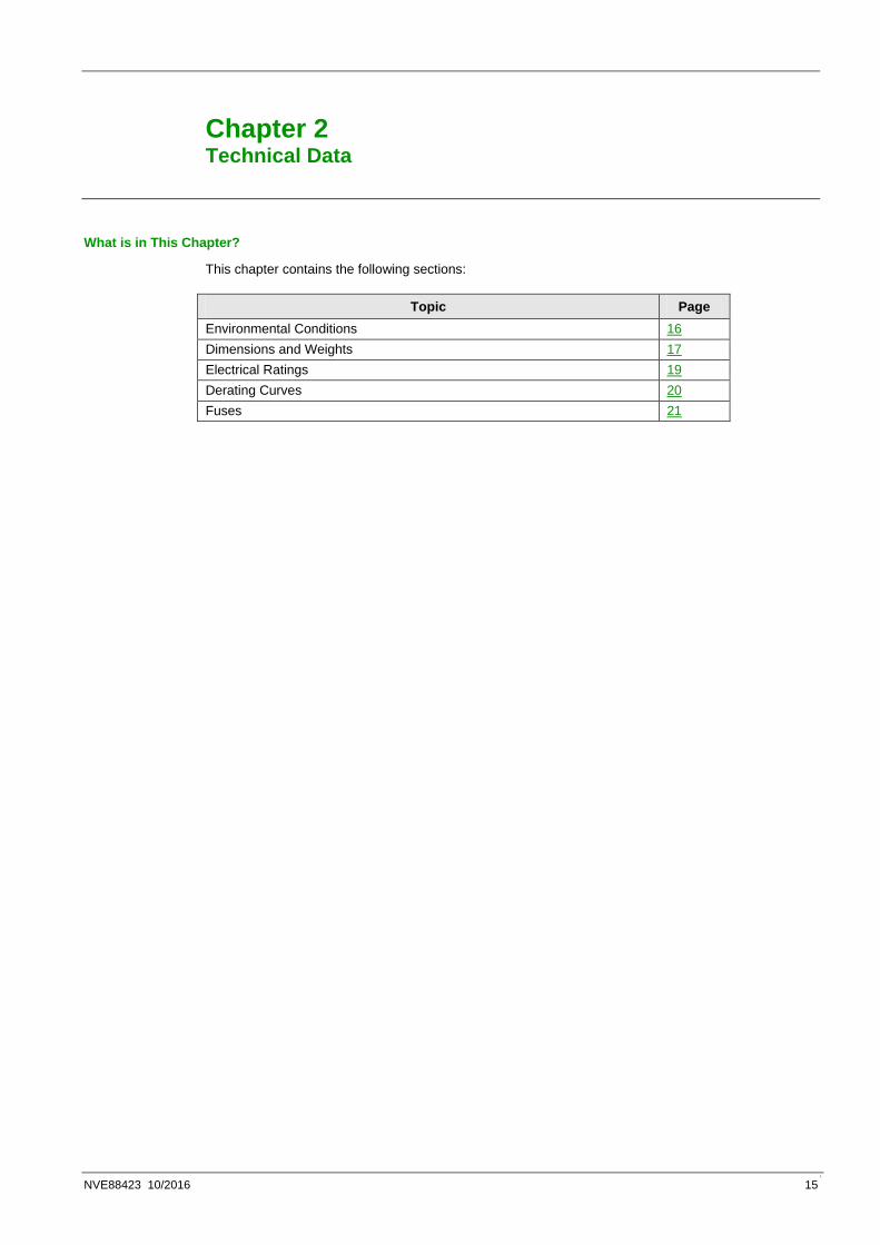
Table of Contents
Safety Information .................................................................................................. 4
About the Book ....................................................................................................... 8
Chapter 1 Introduction ......................................................................................................................... 11Sizing of the Altivar Regenerative Unit ..................................................................................................................... 12
Steps for Setting-Up the Regenerative Unit .............................................................................................................. 13
Altivar Regenerative Unit Overview .......................................................................................................................... 14
Chapter 2 Technical Data ..................................................................................................................... 15Environmental Conditions ......................................................................................................................................... 16
Dimensions and Weights .......................................................................................................................................... 17
Electrical Ratings ...................................................................................................................................................... 19
Derating Curves ........................................................................................................................................................ 20
Fuses ........................................................................................................................................................................ 21
Chapter 3 Regenerative Unit Mounting .............................................................................................. 22Initial Steps ............................................................................................................................................................... 23
Mounting Conditions ................................................................................................................................................. 24
Vertical Flat Mounting ............................................................................................................................................... 26
Side by Side Mounting .............................................................................................................................................. 28
Horizontal Flat Mounting ........................................................................................................................................... 29
Mounting ................................................................................................................................................................... 30
Chapter 4 Regenerative Unit Wiring ................................................................................................... 31Wiring Instructions .................................................................................................................................................... 32
Operation on an IT or Corner Grounded System ...................................................................................................... 34
Disconnecting the Built-in EMC Filter ....................................................................................................................... 35
Wiring the Power Part ............................................................................................................................................... 36
Wiring the Control Part .............................................................................................................................................. 37
Plugging Instructions ................................................................................................................................................. 38
Generic Wiring .......................................................................................................................................................... 41
Regenerative Units and Drive ................................................................................................................................... 42
Drives and Regenerative Unit ................................................................................................................................... 44
Wiring Blocks ............................................................................................................................................................ 46
Chapter 5 Checking Installation .......................................................................................................... 47Before Switching On ................................................................................................................................................. 48
Chapter 6 Diagnostics and Troubleshooting ..................................................................................... 50LED Status ................................................................................................................................................................ 51
Error Description ....................................................................................................................................................... 52
Chapter 7 Maintenance and Diagnostics ........................................................................................... 54Maintenance ............................................................................................................................................................. 55

1
NVE88423 10/2016 4
Safety Information
Important Information
NOTICE
Read these instructions carefully, and look at the equipment to become familiar with the device before trying to install, operate, or maintain it. The following special messages may appear throughout this documentation or on the equipment to inform of potential hazards or to call attention to information that clarifies or simplifies a procedure.
The addition of this symbol to a Danger safety label indicates that an electrical hazard exists, which will result in personal injury if the instructions are not followed.
This is the safety alert symbol. It is used to alert you to potential personal injury hazards. Obey all safety messages that follow this symbol to avoid possible injury or death.
DANGER DANGER indicates an imminently hazardous situation which, if not avoided, results in death or serious injury.
WARNING
WARNING indicates a potentially hazardous situation which, if not avoided, can result in death or serious injury.
CAUTION CAUTION indicates a potentially hazardous situation which, if not avoided, can result in minor or moderate injury.
NOTICE
NOTICE is used to address practices not related to physical injury.

1
NVE88423 10/2016 5
PLEASE NOTE
Electrical equipment should be installed, operated, serviced, and maintained only by qualified personnel. No responsibility is assumed by Schneider Electric for any consequences arising out of the use of this material.
A qualified person is one who has skills and knowledge related to the construction and operation of electrical equipment and its installation, and has received safety training to recognize and avoid the hazards involved.
Qualification Of Personnel
Only appropriately trained persons who are familiar with and understand the contents of this manual and all other pertinent product documentation are authorized to work on and with this product. In addition, these persons must have received safety training to recognize and avoid hazards involved. These persons must have sufficient technical training, knowledge and experience and be able to foresee and detect potential hazards that may be caused by using the product, by changing the settings and by the mechanical, electrical and electronic equipment of the entire system in which the product is used. All persons working on and with the product must be fully familiar with all applicable standards, directives, and accident prevention regulations when performing such work.
Intended Use
This product is a regenerative unit to be used in association with a drive for three-phase synchronous and asynchronous motors and intended for industrial use according to this manual. The product may only be used in compliance with all applicable safety standard and local regulations and directives, the specified requirements and the technical data. The product must be installed outside the hazardous ATEX zone. Prior to using the product, you must perform a risk assessment in view of the planned application. Based on the results, the appropriate safety measures must be implemented. Since the product is used as a component in an entire system, you must ensure the safety of persons by means of the design of this entire system (for example, machine design). Any use other than the use explicitly permitted is prohibited and can result in hazards. Electrical equipment should be installed, operated, serviced, and maintained only by qualified personnel.

1
NVE88423 10/2016 6
Product Related Information
Read and understand these instructions before performing any procedure with this regenerative unit.
DANGER HAZARD OF ELECTRIC SHOCK, EXPLOSION OR ARC FLASH • Only appropriately trained persons who are familiar with and understand the contents of this
manual and all other pertinent product documentation and who have received safety training to recognize and avoid hazards involved are authorized to work on and with this drive system. Installation, adjustment, repair and maintenance must be performed by qualified personnel.
• The system integrator is responsible for compliance with all local and national electrical code requirements as well as all other applicable regulations with respect to grounding of all equipment.
• Many components of the product, including the printed circuit boards, operate with mains voltage. Do not touch. Use only electrically insulated tools.
• Do not touch unshielded components or terminals with voltage present. • Motors can generate voltage when the shaft is rotated. Prior to performing any type of work on the
drive system, block the motor shaft to prevent rotation. • AC voltage can couple voltage to unused conductors in the motor cable. Insulate both ends of
unused conductors of the motor cable. • Do not short across the DC bus terminals or the DC bus capacitors or the braking resistor
terminals. • Before performing work on the drive system:
o Disconnect all power, including external control power that may be present. o Place a Do Not Turn On label on all power switches. o Lock all power switches in the open position. o Wait 15 minutes to allow the DC bus capacitors to discharge. The DC bus LED is not an
indicator of the absence of DC bus voltage that can exceed 800 Vdc. Measure the voltage on the DC bus between the DC bus terminals (PA/+, PC/-) using a properly rated voltmeter to verify that the voltage is <42 Vdc
o If the DC bus capacitors do not discharge properly, contact your local Schneider Electric representative. Do not repair or operate the product.
• Install and close all covers before applying voltage. Failure to follow these instructions will result in death or serious injury.
WARNING
UNANTICIPATED EQUIPMENT OPERATION • Carefully install the wiring in accordance with the EMC requirements. • Perform a comprehensive commissioning test.
Failure to follow these instructions can result in death, serious injury, or equipment damage.

1
NVE88423 10/2016 7
WARNING LOSS OF CONTROL
• The designer of any control scheme must consider the potential failure modes of control paths and, for critical control functions, provide a means to achieve a safe state during and after a path failure. Examples of critical control functions are emergency stop, overtravel stop, power outage and restart.
• Separate or redundant control paths must be provided for critical control functions. • System control paths may include communication links. Consideration must be given to the
implications of unanticipated transmission delays or failures of the link. • Observe all accident prevention regulations and local safety guidelines (1). • Each implementation of the product must be individually and thoroughly tested for proper
operation before being placed into service. Failure to follow these instructions can result in death, serious injury, or equipment damage.
(1) For USA: Additional information, refer to NEMA ICS 1.1 (latest edition), Safety Guidelines for the Application, Installation, and Maintenance of Solid State Control and to NEMA ICS 7.1 (latest edition), Safety Standards for Construction and Guide for Selection, Installation and Operation of Adjustable-Speed Drive Systems.
NOTICE DESTRUCTION DUE TO INCORRECT MAINS VOLTAGE
Before switching on and configuring the product, verify that it is approved for the mains voltage.
Failure to follow these instructions can result in equipment damage.
The temperature of the products described in this manual may exceed 80 °C (176 °F) during operation.
WARNING HOT SURFACES
• Ensure that any contact with hot surfaces is avoided. • Do not allow flammable or heat-sensitive parts in the immediate vicinity of hot surfaces. • Verify that the product has sufficiently cooled down before handling it. • Verify that the heat dissipation is sufficient by performing a test run under maximum load
conditions. Failure to follow these instructions can result in death, serious injury, or equipment damage.
This equipment has been designed to operate outside of any hazardous location. Only install this equipment in zones known to be free of a hazardous atmosphere
DANGER POTENTIAL FOR EXPLOSION
Install and use this equipment in non-hazardous locations only.
Failure to follow these instructions will result in death or serious injury.

1
NVE88423 10/2016 8
About the Book
At a Glance
Document Scope
The purpose of this document is to provide information about: • Mechanical and electrical data related to the Regenerative Unit, • Installation and wiring of the unit, • Displayed information by the LED on the unit, • Troubleshooting and Maintenance.
Validity Note
This document is valid for the Altivar Regenerative Unit intended to be used with Altivar drives range.
Original instructions and information given in this manual have been written in English (before optional translation).
NOTE: The products listed in the document are not all available at the time of publication of this document online. The data, illustrations and product specifications listed in the guide will be completed and updated as the product availabilities evolve. Updates to the guide will be available for download once products are released on the market.
Step Action 1 Go to the Schneider Electric home page www.schneider-electric.com 2 In the Search box type the reference of a product or the name of a product range.
• Do not include blank spaces in the reference or product range. • To get information on grouping similar modules, use asterisks (* ).
3 If you entered a reference, go to the Product Datasheets search results and click on the reference that interests you. If you entered the name of a product range, go to the Product Ranges search results and click on the product range that interests you.
4 If more than one reference appears in the Products search results, click on the reference that interests you.
5 Depending on the size of your screen, you may need to scroll down to see the data sheet. 6 To save or print a data sheet as a .pdf file, click Download XXX product datasheet.
The characteristics that are presented in this manual should be the same as those characteristics that appear online. In line with our policy of constant improvement, we may revise content over time to improve clarity and accuracy. If you see a difference between the manual and online information, use the online information as your reference.

1
NVE88423 10/2016 9
Related Documents
Use your tablet or your PC to quickly access detailed and comprehensive information on all our products on www.schneider-electric.com.
The internet site provides the information you need for products and solutions:
• The whole catalog for detailed characteristics and selection guides,
• The CAD files to help design your installation, available in over 20 different file formats,
• All software and firmware to maintain your installation up to date,
• A large quantity of White Papers, Environment documents, Application solutions,
Specifications... to gain a better understanding of our electrical systems and equipment or automation,
• And finally all the User Guides related to your drive, listed below:
Title of Documentation Reference Number Altivar Regenerative Unit Manual
NVE88423
Altivar Regenerative Unit Sizing Tool
(English)
NVE94856 (English)
ATV320 Installation Manual NVE41289 (English), NVE41290 (French), NVE41291 (German), NVE41292 (Spanish), NVE41293 (Italian), NVE41294 (Chinese)
ATV320 Programming Manual NVE41295 (English), NVE41296 (French), NVE41297 (German), NVE41298 (Spanish), NVE41299 (Italian), NVE41300 (Chinese)
ATV930, ATV950 Installation Manual NHA80932 (English), NHA80933 (French), NHA80934 (German), NHA80935 (Spanish), NHA80936 (Italian), NHA80937 (Chinese)
ATV900 Programming Manual NHA80757 (English), NHA80758 (French), NHA80759 (German), NHA80760 (Spanish), NHA80761 (Italian), NHA80762 (Chinese)
ATV340 Installation Manual NVE61069 (English), NVE61071 (French), NVE61074 (German), NVE61075 (Spanish), NVE61078 (Italian), NVE61079 (Chinese)
ATV340 Programming Manual NVE61643 (English), NVE61644 (French), NVE61645 (German), NVE61647 (Spanish), NVE61648 (Italian), NVE61649 (Chinese)
You can download these technical publications and other technical information from our website at http://download.schneider-electric.com

1
NVE88423 10/2016 10
Standards and Terminology
The technical terms, terminology, and the corresponding descriptions in this manual normally use the terms or definitions in the relevant standards.
In the area of drive systems this includes, but is not limited to, terms such as error, error message, failure, fault, fault reset, protection, safe state, safety function, warning, warning message, and so on.
Among others, these standards include:
• IEC 61800 series: Adjustable speed electrical power drive systems
• IEC 61508 Ed.2 series: Functional safety of electrical/electronic/programmable electronic safety-related
• EN ISO 13849-1 & 2 Safety of machinery - Safety related parts of control systems.
• IEC 60204-1: Safety of machinery - Electrical equipment of machines – Part 1: General requirements

1
NVE88423 10/2016 11
Chapter 1 Introduction
What is in This Chapter?
This chapter contains the following sections:
Topic Page Sizing of the Altivar Regenerative Unit Steps for Setting-Up the Regenerative Unit
12
Altivar Regenerative Unit Overview13
14

1
NVE88423 10/2016 12
Sizing of the Altivar Regenerative Unit
Sizing Diagram
To determine the number and the size of Altivar Regenerative Units you need, refer to the Altivar Regenerative Unit Sizing Tool (NVE94856).
Generic diagram for Altivar regenerative unit used with Altivar drives:
(1): Motor characteristics: o Motor rated power o Motor efficiency
(2): Gearbox efficiency

1
NVE88423 10/2016 13
Steps for Setting-Up the Regenerative Unit
q Connect the Regenerative Unit to the 3-phase supply (L1, L2, L3)
q Connect the Regenerative Unit to the Drive DC-bus
q Connect the control cable if several units are used
Wire the Regenerative Unit 4
5 Configure the Drive
2 Verify the supply mains
q Verify that the supply mains is compatible with the voltage range of the Regenerative Unit
q Mount the Regenerative Unit in accordance with the instructions in this document
3
1 Receive and inspect the Regenerative Unit• Verify that the catalog number printed on the label is the same on the purchase
order.• Remove the Regenerative Unit from its packaging and verify that it has not been
damaged.
Install the Regenerative Unit
6 Start the Drive

1
NVE88423 10/2016 14
Altivar Regenerative Unit Overview
Frame Size
Frame size ATVRU75N4 Frame size ATVRD15N4 3-phase 380 / 500 Vac, 2.2…7.5 kW 3-phase 380 / 500 Vac, 11…15 kW
General Description
1
NVE88423 10/2016 15
Chapter 2 Technical Data
What is in This Chapter?
This chapter contains the following sections:
Topic Page Environmental Conditions Dimensions and Weights
16
Electrical Ratings17
Derating Curves
19
Fuses20
21

NVE88423 - 10/2016 16
Environmental Conditions
Withstand to harsh environments
• Chemical class 3C3 conforming to IEC/EN 60721
• Mechanical class 3S2 conforming to IEC/EN 60721
Temperature Conditions
Ambient air temperature
For Temperature Comments Long term storage °C -25…55 According to class 1K4 of
IEC60721-3-1 °F -13…131 Storage and transportation °C -40…70 According to class 2K4 of
IEC60721-3-2 °F -40…158 Operation °C -10…50 Without derating
(For vertical mounting only) °F 14…122 °C 50…60 With derating °F 122…140
Relative Humidity
5...95% without condensation or dripping water.
Operating Altitude
Operating altitude Derating m Up to 1000 Without
ft Up to 3280
m 1000…2000 Braking power must be reduced by 1% every 100 m (328 ft) over 1000 m (3280 ft)
ft 3280…6560
m 2000…3000 Braking power must be reduced by 1% every 100 m (328 ft) over 1000 m (3280 ft). Direct use on corner grounded mains power supply is not allowed.
ft 6560…9840
Pollution Degree and Degree of Protection
Regenerative Unit Pollution Degree Degree of Protection ATVRU75N4 2 IP20 ATVRD15N4 2 IP20

NVE88423 - 10/2016 17
Dimensions and Weights
About The Drawings
All drawings CAD files can be downloaded from www.schneider-electric.com
ATVRU75N4
Dimensions
Weight
Catalog Number Weight in kg (lb)
ATVRU75N4 6.0 (13.23)

NVE88423 - 10/2016 18
ATVRD15N4
Dimensions
Weights
Catalog Number Weight in kg (lb)
ATVRD15N4 11.5 (24.25)

NVE88423 - 10/2016 19
Electrical Ratings
Mains Operating Voltage
Mains side Value Accuracy Minimum 380 Vac -15 % Maximum 500 Vac + 10 % Frequency 45…65 Hz - Maximum voltage unbalance 3%
DC-bus Operating Voltage
DC-bus side Value Minimum 300 Vdc Operating voltage 456…778 Vdc Maximum 880 Vdc
Operating Power and Currents
Continuous Operation
Ratings Altivar Regenerative Unit
ATVRU75N4 ATVRD15N4
380 Vac 500 Vac 380 Vac 500 Vac DC DC-bus Input Power (kW) 6.8 6.8 13.5 13.5
RMS Current (A) 16.5 14.5 31.8 27.9 AC RMS Current (A) 13.4 11.9 25.9 23.2
Transient Operation for 60s
Ratings Altivar Regenerative Unit
ATVRU75N4 ATVRD15N4
380 Vac 500 Vac 380 Vac 500 Vac DC DC-bus Input Power (kW) 10.2 10.2 20.3 20.3
RMS Current (A) 22.9 19.1 43.1 36.3 AC RMS Current (A) 18.4 15.4 36.5 29.7
NVE88423 - 10/2016 20
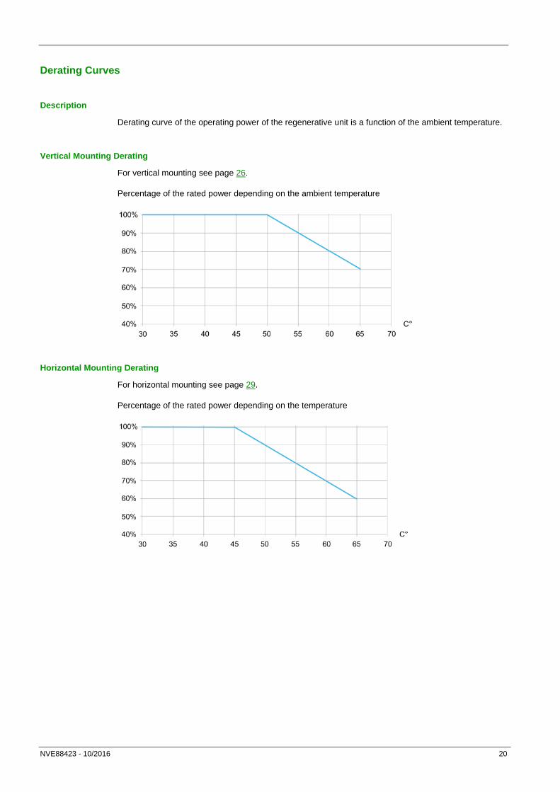
Derating Curves
Description
Derating curve of the operating power of the regenerative unit is a function of the ambient temperature.
Vertical Mounting Derating
For vertical mounting see page 26.
Percentage of the rated power depending on the ambient temperature
Horizontal Mounting Derating
For horizontal mounting see page 29.
Percentage of the rated power depending on the temperature

NVE88423 - 10/2016 21
Fuses
Fuse Selection Table
Maximum braking power on DC bus (kW)
DC fuses ratings Regenerative unit
Minimum current rating (A)
Max I²t (A².s)
0.33 3 300 ATVRU75N4 0.50 5 300
0.68 6 300 1.0 7 300 1.4 9 300 2.0 14 300 2.7 17 300 3.6 21 685 5.0 24 685 6.8 30 1100 9.9 40 1900
ATVRD15N4 13.5 40 3100 NOTE: Protection fuses on the DC lines must be selected in the semiconductors protection class.
Mains Protections
In rated conditions for each regenerative unit the protections below can be used:
• ATVRU75N4: circuit breaker GV2L32 or three fuses 40A, 600V class J.
• ATVRD15N4: circuit breaker GV2L50 or three fuses 70A, 600V class J.
Short Circuit Current Ratings
The maximum AC mains SCCR of the Regenerative Unit is 100 kA. In association with a drive whose AC mains SCCR is lower than this value, the drive value will apply.

NVE88423 - 10/2016 22
Chapter 3 Regenerative Unit Mounting
What is in This Chapter?
This chapter contains the following sections:
Topic Page Initial Steps Mounting Conditions
23
Vertical Flat Mounting24
Side by Side Mounting
26
Horizontal Flat Mounting28
Mounting
29
30

NVE88423 - 10/2016 23
Initial Steps
Handling and Storage
To help protect the Regenerative Unit before installation, handle and store the device in its packaging. Ensure that the ambient conditions are acceptable
Check the Delivery of the Regenerative Unit
Damaged products or accessories may cause electric shock or unanticipated equipment operation.
DANGER ELECTRIC SHOCK OR UNANTICIPATED EQUIPMENT OPERATION
Do not use damaged products or accessories.
Failure to follow these instructions will result in death or serious injury.
Contact your local Schneider Electric sales office if you detect any damage whatsoever.
Step Action 1 Remove the regenerative unit from the packaging and verify that it has not been damaged 2 Verify that the catalog number printed on the nameplate corresponds to the purchase
order. 3 Check that the following parts are in the packaging:
• Danger labels kit in different languages • Altivar regenerative unit instruction sheet • Hazardous substance list • Plug parts (1) • Wiring traps (2) • Screws (3)

NVE88423 - 10/2016 24
Mounting Conditions
Before You Begin
Conductive foreign objects, dust or liquids or damaged parts may cause parasitic voltage.
DANGER ELECTRIC SHOCK OR UNANTICIPATED EQUIPMENT OPERATION
• Do not use damaged products. • Keep foreign objects such as chips, screws or wire clippings from getting into the product. • Verify correct seat of seals and cable entries in order to avoid deposits and humidity.
Failure to follow these instructions will result in death or serious injury.
The temperature of the products described in this manual may exceed 80 °C (176 °F) during operation.
WARNING HOT SURFACES • Ensure that any contact with hot surfaces is avoided. • Do not allow flammable or heat-sensitive parts in the immediate vicinity of hot surfaces. • Verify that the product has sufficiently cooled down before handling it. • Verify that the heat dissipation is sufficient by performing a test run under maximum load conditions.
Failure to follow these instructions can result in death, serious injury, or equipment damage.
Power Drive Systems (PDS) can generate strong local electrical and magnetic fields. This can cause interference in electromagnetically sensitive devices.
WARNING ELECTROMAGNETIC FIELDS
• Keep persons with electronic medical implants, such as pacemakers, away from the equipment.
• Do not place electromagnetically sensitive devices in the vicinity of the equipment. Failure to follow these instructions can result in death, serious injury, or equipment damage.
Attaching a Label with Safety Instructions
A label kit is provided with the regenerative unit.
Step Action 1 Observe the safety regulations in the targeted country 2 Select the label with the suitable language for the targeted country 3 Attach the label to the front of the device and make sure that it is visible. Below is the
English version
NVE88423 - 10/2016 25
General Mounting Instructions
• The use of washers is required with all mounting screws.
• Tighten the fixation screws
• Do not mount the device close to heat sources.
• Avoid environmental effects like high temperatures and high humidity as well as dust, dirt and conductive gases.
• Adhere to the minimum installation distances for required cooling.
• Do not mount the device on flammable materials.
• Install the unit on solid, vibration-free support.
NVE88423 - 10/2016 26
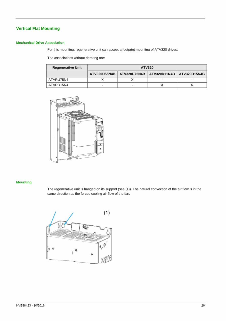
Vertical Flat Mounting
Mechanical Drive Association
For this mounting, regenerative unit can accept a footprint mounting of ATV320 drives.
The associations without derating are:
Regenerative Unit ATV320
ATV320U55N4B ATV320U75N4B ATV320D11N4B ATV320D15N4B ATVRU75N4 X X - - ATVRD15N4 - - X X
Mounting
The regenerative unit is hanged on its support (see (1)). The natural convection of the air flow is in the same direction as the forced cooling air flow of the fan.

NVE88423 - 10/2016 27
These pictures show dimensions for enclosure mounting:
(1): Fixing holes for ATV320

NVE88423 - 10/2016 28
Side by Side Mounting
Drive Association
The regenerative unit is hanged on its support. It can be mounted side by side with other regenerative unit(s), or with Altivar:
Mounting
This picture shows dimensions for enclosure mounting:

NVE88423 - 10/2016 29
Horizontal Flat Mounting The regenerative unit is mounted horizontally. The forced cooling air of the fan is orthogonal to the natural convection air flow. A derating shall be applied to the regenerative unit

NVE88423 - 10/2016 30
Mounting
Mounting Holes and Screws
Fixation by screws is required for all regenerative unit ratings:
• Number of holes: use the 4 mounting holes.
Top hole
Frame Size Top Holes a mm (in.)
Top Holes B (if any) mm (in.)
Bottom holes mm (in.)
Recommended Screws
ATVRU75N4 5 (0.2) 10 (0.4) 5 (0.2) M4 ATVRD15N4 6 (0.24) 11 (0.43) 6 (0.24) M5

NVE88423 - 10/2016 31
Chapter 4 Regenerative Unit Wiring
What is in This Chapter?
This chapter contains the following sections:
Topic Page Wiring Instructions Wiring the Power Part
32
Wiring the Control Part36
Ground Cables
37
Plugging Instructions36
Generic Wiring
38
Regenerative Units and Drive41
Drives and Regenerative Unit
42
Wiring Blocks44
46

NVE88423 - 10/2016 32
Wiring Instructions
General Instructions
WARNING UNANTICIPATED EQUIPMENT OPERATION
• Carefully install the wiring in accordance with the EMC requirements. • Perform a comprehensive commissioning test.
Failure to follow these instructions can result in death, serious injury, or equipment damage.
DANGER HAZARD OF FIRE OR ELECTRIC SHOCK
• Wire cross sections and tightening torques must comply with the specifications provided in this document • Do not use multi-conductor cables without cable plugs for any connection with a voltage higher than 25 Vac.
Failure to follow these instructions will result in death or serious injury.
The product has a leakage current greater than 3.5 mA. If the protective ground connection is interrupted, a hazardous touch current may flow if the product is touched.
DANGER ELECTRIC SHOCK CAUSED BY HIGH LEAKAGE CURRENT
• Verify compliance with all local and national electrical code requirements as well as all other applicable regulations with respect to grounding of the entire drive system.
Failure to follow these instructions will result in death or serious injury.
Power and Circuit Protection
Where local and national codes require upstream protection with a residual current device, use a type ASi device.
Choose a suitable model integrating: • High frequency current filtering, • A time delay that helps to prevent a triggering of the upstream device caused by the load from stray
capacitance on power-on. The time delay is not available for 30 mA device; in this case, choose devices with immunity against nuisance triggering.
Due to high leakage current in standard operation, we recommend to choose at least a 300 mA device. If the installation requires a residual current device less than 300 mA, it can be possible to use a device lower than 300 mA by removing the screws according to the instructions given in the installation manual of the drive product
If the installation includes several drives, provide one residual current device per drive.

NVE88423 - 10/2016 33
Equipment Grounding
NOTICE DESTRUCTION DUE TO INCORRECT WIRING
Before switching on and configuring the product, verify that it is properly wired.
Failure to follow these instructions can result in equipment damage.
DANGER ELECTRIC SHOCK CAUSED BY INSUFFICIENT GROUNDING
• Verify compliance with all local and national electrical code requirements as well as all other applicable regulations with respect to grounding of the entire drive system. • Ground the drive system before applying voltage. • The cross section of the protective ground conductor must comply with the applicable standards. • Do not use conduits as protective ground conductors; use a protective ground conductor inside the conduit. • Do not consider cable shields to be protective ground conductors.
Failure to follow these instructions will result in death or serious injury.
• Ensure that the resistance to ground is 1 Ohm or less.
• When grounding several regenerative units, you must connect each one directly, as shown in the above figure?
• Do not loop ground cables or connect them in series.

NVE88423 - 10/2016 34
Operation on an IT or Corner Grounded System
Definition
IT system: Isolated or impedance grounded neutral. Use a permanent insulation monitoring device compatible with nonlinear loads, such as an XM200 type or equivalent.
Corner grounded system: System with one phase grounded.
Operation
NOTICE RISK OF DAMAGE TO THE REGENERATIVE UNIT
If the regenerative unit is used on an IT or corner grounded system, the built-in EMC filter must be disconnected as described in this manual.
Failure to follow these instructions can result in equipment damage.

NVE88423 - 10/2016 35
Disconnecting the Built-in EMC Filter
Filter Disconnection
DANGER HAZARD OF ELECTRIC SHOCK, EXPLOSION OR ARC FLASH
Read and understand the instructions in Safety Information chapter before performing any procedure in this chapter.
Failure to follow these instructions will result in death or serious injury.
The regenerative unit has a built-in EMC filter. As a result they exhibit leakage current to ground. If the leakage current creates compatibility problems with your installation (residual current device or other), then you can reduce the leakage current by disconnecting the built-in filter as shown below. In the configuration the product does not meet the EMC requirements according to the standard IEC 61800-3.
Setting
Apply the following instructions to disconnect the built-in EMC filter.
Step Action 1
Locate the disconnect built-in EMC screw as shown on detail 1 2 For operation without the built-in EMC filter, remove the screw from its location.
NOTE:

NVE88423 - 10/2016 36
Wiring the Power Part
Before Wiring
Observe the following instructions before wiring:
• DC-bus link length between drive and regenerative unit or two units should not exceed
2 m (6.56 ft)
• Cables of DC-bus link (positive, negative and protective ground cables) have to be less than 5cm (2 in.) apart from each other
NOTE: It is recommended to use sheathed cable
Characteristics of the Power Part Terminals
Regenerative Unit
AC Terminals DC Terminals
Wire Cross Section Tightening Torque
Wire Cross Section Tightening Torque
Minimum Maximum Rated Minimum Maximum Rated
mm² (AWG)
mm² (AWG)
N.m (lb.in)
mm² (AWG)
mm² (AWG)
N.m (lb.in)
ATVRU75N4 2.5 (12) 4 (10) 0.8 (7) 2.5 (12) 4 (10) 0.8 (7) ATVRD15N4 6 (8) 6 (8) 1.7 (15) 6 (8) 6 (8) 1.7 (15)
Functions of the Power Terminals
Terminal Function
Ground terminal R/L1 – S/L2 – T/L3 Power supply PA/+ DC bus + polarity PC/- DC bus - polarity
Ground Cables
Ground cable cross sections of input and output ground cables are the same as those given for the input and output cables. Minimum cross section of protective ground cable is 10 mm² (AWG 8).
Tightening torque is 2.5 N.m.

NVE88423 - 10/2016 37
Wiring the Control Part
Characteristics of the Control Part Terminals
Regenerative Unit
Control Terminals
Wire Cross Section Tightening Torque
Minimum Maximum Rated
mm² (AWG) mm² (AWG) N.m (lb.in) ATVRU75N4 0.5 (20) 1.5 (16) 0.5 (4.4) ATVRD15N4 0.5 (20) 1.5 (16) 0.5 (4.4)
Functions of the Control Terminals
Terminal Function I/O Type Electrical characteristics 24V 24 Vdc Power supply O • Maximum current : 250mA
• Tolerance : -15/+20% DI/DQ Digital Input / Digital Output I/O Only for paralleling of Altivar
regenerative unit COM Digital I/O common I/O 0V NOTE: see page 42 for the wiring of the control terminal
NVE88423 - 10/2016 38
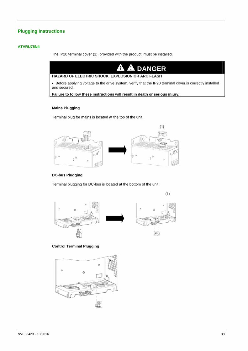
Plugging Instructions
ATVRU75N4
The IP20 terminal cover (1), provided with the product, must be installed.
DANGER HAZARD OF ELECTRIC SHOCK. EXPLOSION OR ARC FLASH
• Before applying voltage to the drive system, verify that the IP20 terminal cover is correctly installed and secured.
Failure to follow these instructions will result in death or serious injury.
Mains Plugging
Terminal plug for mains is located at the top of the unit.
DC-bus Plugging
Terminal plugging for DC-bus is located at the bottom of the unit.
Control Terminal Plugging

NVE88423 - 10/2016 39
ATVRD15N4
The IP20 terminal cover (1), provided with the product, must be installed.
DANGER HAZARD OF ELECTRIC SHOCK. EXPLOSION OR ARC FLASH
• Before applying voltage to the drive system, verify that the IP20 terminal cover is correctly installed and secured.
Failure to follow these instructions will result in death or serious injury.
Mains Plugging
Terminal plug for mains is located at the top of the unit.
DC-bus Plugging
Control Terminal Plugging
Control terminal plug is located at the bottom of the unit:

NVE88423 - 10/2016 40
Protective Ground
Connect the protective ground cable at the top and bottom of the unit:

NVE88423 - 10/2016 41
Generic Wiring
Drive and Regenerative Unit Wiring Diagram
(1): AC protection fuses (2): Optional additional EMC input Filter (see drive catalog) (3): Optional AC Choke (see drive catalog) (4): DC bus link (5): DC protection fuses

NVE88423 - 10/2016 42
Regenerative Units and Drive
One Drive with One to Three Regenerative Units
Using several regenerative units in parallel, the DC-bus connection between 2 regenerative units must not be wired directly on the second slot of the terminals (PA/+, PC/-) available on the regenerative units.
DANGER HAZARD OF ELECTRIC SHOCK, EXPLOSION, OR ARC FLASH
Use the wiring block specified at the page 46.
Failure to follow these instructions will result in death or serious injury.
(1): AC protection fuses (2): Optional EMC filter (see drive catalog) (3): Optional choke (see drive catalog) (4): Control link between regenerative units (5): DC protection fuses (6): DC-bus link (7): Wiring block and bridge (see reference page 46)

NVE88423 - 10/2016 43
One Drive with One to Three Regenerative Units Using Wiring Blocks
Using several regenerative units in parallel, the DC-bus connection between 2 regenerative units must not be wired directly on the second slot of the terminals (PA/+, PC/-) available on the regenerative units.
DANGER HAZARD OF ELECTRIC SHOCK, EXPLOSION, OR ARC FLASH
Use the wiring block specified at the page 46.
Failure to follow these instructions will result in death or serious injury.
(1): AC protection fuses (2): Optional EMC filter (see drive catalog) (3): Optional choke (see drive catalog) (4): Control link between regenerative units (5): DC protection fuses (6): DC-bus link (7): Wiring block and bridge (see reference page 46)

NVE88423 - 10/2016 44
Drives and Regenerative Unit
ATVRD15N4 Used With Two Drives
(1): AC protection fuses (2): Optional EMC filter (see drive catalog) (3): Optional choke (see drive catalog) (4): DC protection fuses (5): DC-bus link NOTE: In this case the total braking power of the two drives in the worst case of the application must be lower or equal to the rated power of ATVRD15N4
Drives DC fuses must be selected from table page 21 according to the maximum braking power of each drive
Association Table With DC Fuses
Drive Power Rating (kW)
Regenerative Unit 1 Regenerative Unit 2 Regenerative Unit 3
Catalog number
DC fuse Catalog number
DC fuse Catalog number
DC fuse
Rating (A)
I²t (A².s)
Rating (A)
I²t (A².s)
Rating (A)
I²t (A².s)
18.5 ATVRD15N4 50 < 1900 ATVRU75N4 25 < 650 - - - 22 ATVRD15N4 60 < 3100 ATVRU75N4 30 < 1100 - - - 30 ATVRD15N4 60 < 3100 ATVRD15N4 60 < 3100 - - - 37 ATVRD15N4 60 < 3100 ATVRD15N4 60 < 3100 ATVRU75N4 30 < 1100 45 ATVRD15N4 60 < 3100 ATVRD15N4 60 < 3100 ATVRD15N4 60 < 3100

NVE88423 - 10/2016 45
Multiple Drives with One Regenerative Unit Wiring
(1): AC protection fuses (2): Optional EMC filter (3): Optional AC Choke (4): DC-bus protection fuses (5): DC-bus Link (6): Wiring block and bridge (see reference page 46) The power rating of the regenerative unit must be greater or equal to the maximum regenerated power of the drives in the worst case of the application.
Drives and regenerative units have to be wired in the following order:
• Highest drive power close to the regenerative unit
• Then other drives sorted by power ratings
The drive must follow the instructions defined by the drives application note to share the same DC bus (wiring recommendations, DC fuses selection, use of line chokes…).

NVE88423 - 10/2016 46
Wiring Blocks
References
When using regenerative units in parallel it is recommended to use wiring blocks with bridge available on www.schneider-electric.com.
This table shows the wiring blocks with bridge according to the power rating.
Ratings Terminal block – bridge catalog number
NSYTRV102 – NSYTRAL102
NSYTRV162 – NSYTRAL162
NSYTRV352 – NSYTRAL352
Maximum Power (kW)
22 30 37 and 45
Rated current (A)
51 66 84
Peak current (A)
68 88 112
Rated section (mm²)
10 16 35
Plugging
Terminal block and bridge plugging:

NVE88423 - 10/2016 47
Chapter 5 Checking Installation
What is in This Chapter?
This chapter contains the following sections:
Topic Page Before Switching On
48

NVE88423 - 10/2016 48
Before Switching On
Unsuitable settings or unsuitable data or unsuitable wiring may trigger unintended movements, trigger signals, damage parts and disable monitoring functions.
WARNING UNANTICIPATED EQUIPMENT OPERATION
• Only start the system if there are no persons or obstructions in the zone of operation. • Verify that a functioning emergency stop push-button is within reach of all persons involved in the operation. • Do not operate the drive system with unknown settings or data. • Verify that the wiring is appropriate for the settings. • Never modify a parameter unless you fully understand the parameter and all effects of the modification. • When commissioning, carefully run tests for all operating states, operating conditions and potential error situations. • Anticipate movements in unintended directions or oscillation of the motor.
Failure to follow these instructions can result in death, serious injury, or equipment damage.
If the power stage is disabled unintentionally, for example as a result of power outage, errors or functions, there is a possibility that the motor is no longer decelerated in a controlled way.
WARNING UNANTICIPATED EQUIPMENT OPERATION
Verify that movements without braking effect cannot cause injuries or equipment damage.
Failure to follow these instructions can result in death, serious injury, or equipment damage.

NVE88423 - 10/2016 49
Mechanical Installation
Verify the mechanical installation of the entire regenerative unit:
Step Verify that… 1 The installation meets the specified distance requirements. 2 All fastening screws are tightened using the specified tightening torque.
Electrical Installation
Verify the electrical connections and the cabling:
Step Verify that… 1 All protective ground conductors are connected 2 All fuses and circuit breaker have the correct rating. 3 All wires are connected or insulated at the cable ends. 4 All cables and connectors are properly connected and installed. 5 Signal wires are properly connected. 6 The required shield connections are EMC compliant. 7 All measures for EMC compliance are taken.
Covers and Seals
Verify that all devices are properly installed to meet the required degree of protection (see page 38)
Setting on drive
.
Ensure that the following parameters are set as bellow:
• On ATV320, set [DC-Bus chaining] dCCM to [Bus & Main] Main NOTE: SCF3 error will be triggered by the drive if this setting is not correctly applied on the drive.
• On ATV320, ATV930 and ATV340, set [Dec.Ramp Adapt] brA to [No] nO

NVE88423 - 10/2016 50
Chapter 6 Diagnostics and Troubleshooting
Overview
This part describes the various types of diagnostics and provides troubleshooting assistance.
DANGER HAZARD OF ELECTRIC SHOCK, EXPLOSION OR ARC FLASH
Read and understand the instructions in Safety Information chapter before performing any procedure in this chapter.
Failure to follow these instructions will result in death or serious injury.
What is in This Chapter?
This chapter contains the following sections:
Topic Page LED Status Error Description
51
52

NVE88423 - 10/2016 51
LED Status
LED On the Altivar Regenerative Unit
The following diagram shows the LED on the Altivar regenerative unit.
Normal Operations
This diagram shows the LED states in normal operations.
During normal operations, LED indicates several states.
LED Status Regenerative Unit State Description OFF Not operational The regenerative unit is not operational. Red on Operational The regenerative unit is in standby. It is ready
to operate. Red continuous flashing Operating The unit is in regenerative mode.
Error detection
This diagram shows the LED states if an error is detected.

NVE88423 - 10/2016 52
Error Description
Error on the Regenerative Unit
When the Unit detects an error, there are several flashing modes according to the corresponding error.
LED Status Error Probable Cause Remedy 1 flash Input phase loss. One of the 3 AC input
phases is missing. • Verify the correct wiring of the AC input
terminal of the regenerative unit. • Verify the input AC protection (fuses or
circuit breaker) This error is cleared automatically after the cause has been removed.
2 flashes Under voltage. The voltage on terminal + and – is less than 300 Vdc.
• Verify the correct wiring of the regenerative unit DC terminals.
• Verify that power is applied on the drive linked to the DC bus.
• Verify the DC protection fuses. This error is cleared automatically after the DC bus voltage becomes greater than 370 Vdc.
3 flashes Over temperature. • Internal heatsink has reached the maximum temperature.
• Excessive operation cycles have been performed.
• Verify that the regenerative unit cooling fan is running during regenerative operation.
• Verify that the ambient temperature conforms with the regenerated power according to the derating curves.
• Verify the sizing of the regenerative unit in normal and over load operations.
If this error is detected by the heatsink temperature, it will be cleared automatically if the internal temperature decreases. If this error is detected by excessive operating cycles:
• Verify the sizing of the installation. This detected error requires a power reset.
4 flashes Over voltage. • AC mains power supply voltage is greater than 500 Vac +10%.
• DC voltage becomes greater than the maximum allowed during operation because the maximum regenerative capability of the unit has been exceeded.
• Verify the mains supply. The detected error requires a power reset.
• Reduce the regenerative power on the drive or add another regenerative unit in.
This error is cleared automatically after the DC bus voltage has decreased.
5 flashes Over current. The maximum current has been reached. The probable causes are:
• A short circuit on mains inputs.
• Internal short circuit.
• Verify mains input wiring, cables, protection (fuses and/or circuit breaker).
• Contact your local Schneider Electric representative.
This detected error requires a power reset.
6 flashes Internal error. Internal error detected. Verify if the error can be cleared with a power reset of the regenerative unit. If the error is still active contact your local Schneider Electric representative.

NVE88423 - 10/2016 53
Error code on the drive
Error Probable Cause Remedy [DC Bus Overvoltage] OBF on the drive product.
• Sizing of the installation.
• Internal 24 Vdc error if the control link is used.
• Tripped DC fuses (PA/+ PC/-)
• Verify the sizing of the installation.
• In case of no voltage between P24 and COM contact your local Schneider Electric representative.
• Verify the DC fuses

NVE88423 - 10/2016 54
Chapter 7 Maintenance and Diagnostics
What is in This Chapter?
This chapter contains the following sections:
Topic Page Maintenance
55

NVE88423 - 10/2016 55
Maintenance
Limitation of Warranty
The warranty does not apply if the product has been opened, except by Schneider Electric services.
Servicing
DANGER HAZARD OF ELECTRIC SHOCK, EXPLOSION OR ARC FLASH
Read and understand the instructions in Safety Information chapter before performing any procedure in this chapter.
Failure to follow these instructions will result in death or serious injury.
NOTICE RISK OF DAMAGE TO THE REGENERATIVE UNIT
Perform the following activities
Failure to follow these instructions can result in equipment damage.
Environment Part concerned Action Periodicity Mechanical impact on the product
Housing – LED Verify the visual aspect of the unit.
At least each year
Corrosion Terminals – connector – screws
Inspect and clean if required
Dust Terminals – fans blowholes
Cooling Fan Verify the fan operation Replace the fan After 3 to 5 years,
depending on the operating conditions
Vibration Terminal connections Verify tightening at recommended torque
At least each year
Spares and Repairs
Serviceable products. Please contact your Schneider Electric representative.

NVE88423 - 10/2016 56
Fan Replacement
It is possible to order a new fan for the regenerative unit maintenance.
To replace the regenerative unit fan you have to:
Step Action 1 Order a fan on www.schneider-electric.com
• For ATVRU75N4: reference: VZ3V1302 • For ATVRD15N4: reference: VX5VPS1001
2 Remove the fan from the regenerative unit:
3 Remove the new fan from its support :
4 Place the new fan on the regenerative unit fan support:
5 Place the fan on its support in the regenerative unit:

ATV_Regenerative_Unit_Manual_EN_NVE88423_01
11/2016


![Altivar Process EAV64318 04/2015 Altivar Process · Altivar Process EAV64318 04/2015 Altivar Process Variable Speed Drives ATV630, ... [Pumps configuration] ... FLM- Menu ...](https://static.fdocuments.us/doc/165x107/5aec00a27f8b9a36698f1358/altivar-process-eav64318-042015-altivar-process-eav64318-042015-altivar-process.jpg)