Altivar 71 - Schneider Electric Altivar 58 hardware identification Before selecting the Altivar 71,...
83
Transition manual Altivar 71 Migration from ATV58(F) V ATV71
Transcript of Altivar 71 - Schneider Electric Altivar 58 hardware identification Before selecting the Altivar 71,...

Transition manual
Altivar 71
Migration from ATV58(F) V ATV71

The purpose of this document is to help you replace an Altivar 58(F) with an Altivar 71 from version V1.1 ie01.
Sphere of application:
- Constant torque applications- Replacement of Altivar 58 and Altivar 58F drives on the following ranges:
200 V 240 V single and three-phase380 V 480 V three-phase.
It can be used to select the Altivar 71 and its various options or accessories according to the hardware configuration that was used on theAltivar 58(F).
The Altivar 71 does in fact incorporate additional functions such as the number of I/O, application functions, operating temperature, etc. The document also contains recommendations for installation and wiring. An Altivar 58(F) software configuration can be migrated to an Altivar 71 quickly and easily with the PowerSuite v2.20 software workshop.

3
Table of Contents
Table of Contents _____________________________________________________________________________________________ 3Determining catalog numbers____________________________________________________________________________________ 6
Choosing the Altivar 71 catalog number _____________________________________________________________________ 8Selecting the power circuit options ________________________________________________________________________ 12Mounting accessories __________________________________________________________________________________ 13Control circuit options __________________________________________________________________________________ 14Selecting I/O extension cards (VW3A58201, VW3A58202) _____________________________________________________ 15Selecting communication channels ________________________________________________________________________ 20
Drive setup _________________________________________________________________________________________________ 22Installation ___________________________________________________________________________________________ 22Comparison of dimensions ______________________________________________________________________________ 27Mounting the RFI filter __________________________________________________________________________________ 29Kit for flange-mounting in a dust and damp proof enclosure _____________________________________________________ 34NEMA mounting kits ___________________________________________________________________________________ 35Separate control card power supply _______________________________________________________________________ 37Remote display terminal ________________________________________________________________________________ 37Power wiring _________________________________________________________________________________________ 38
Setup for the Altivar 71 communication option cards _________________________________________________________________ 44General _____________________________________________________________________________________________ 44Communication via Modbus network _______________________________________________________________________ 46Communication via Unitelway/Modbus network and VW3 A3 303 option card _______________________________________ 49Communication via CANopen network _____________________________________________________________________ 50Communication via Profibus DP network ___________________________________________________________________ 52Communication via Fipio network – VW3 A3 301 option card ____________________________________________________ 54Communication via Fipio network – VW3 A3 311 option card ____________________________________________________ 56Communication via Interbus network _______________________________________________________________________ 58Communication via Modbus Plus network ___________________________________________________________________ 59Communication via DeviceNet network _____________________________________________________________________ 61Communication via Ethernet network ______________________________________________________________________ 70AS-i ________________________________________________________________________________________________ 79Application-specific option cards __________________________________________________________________________ 82
Steps for setting up the drive
b 1 Identifying the existing ATV 58(F)v Make an inventory of your Altivar 58(F) installation.
Steps 3 and 4 must be performed with the power off
b 2 Selecting the ATV 71v Determine the Altivar 71 catalog numberv Choose the various options required
b 3 Mountingv Mount the drive in accordance with the
instructions in this document, using the substitution kit
v Install any internal and external options
b 4 Wiringv Connect the motor, ensuring that its
connections correspond to the voltagev Connect the controlv Connect the speed referencev Connect the line supply, after making
sure that the power is off
Migration from ATV 58(F) ATV 71
b 5 Configurationv Drivev Communication cards
V
4

Altivar 58 hardware identification
Before selecting the Altivar 71, the Altivar 58 hardware configuration needs to be determined carefully.
1 Measure the line voltage and indicate the type of power supply:
Line voltage:_________V Single phase Three-phase
2 Note down the drive catalog number, which appears on the Altivar 58 nameplate:
ATV58______________________
3 Determine whether the drive is used with high torque (170% Tn) or standard torque (120% Tn), by referring to page 6.
High torque Standard torque
4 Note down the catalog number of any EMC filter installed under the drive:
VW3A584 ___________________
5 Note down the catalog number of any option cards installed in the Altivar 58; this can be found on the label attached to the card:
VW3A58_____________________
6 Note down whether the operator terminal is used:
VW3A58101: yes no
Is the operator terminal connected remotely on the enclosure door?
yes no
7 For ATV-58pU09M2 and U18M2 drives, note whether a braking module is present:
VW3A58701: yes no
8 Note down the catalog number of the NEMA type 1 mounting kit, if used:
VW3A5885___________________
9 Note down the catalog number of the control card fan kit, if used:
VW3A5882___________________
10 Make sure you have the diagrams for the existing installation.
Input V : 200/240V-50/60HzInput phase : 1Input I : 4.4/3.9AInput fuse : Type CC or J : 6A Max
Output 3 Ph : 200/240VOutput I : 2.1AOutput I max. transient (1mn) : 3.2AOutput frequency : 0.5-320Hz
Serial N . 1703001070 France - 6W 9720
LISTED 170MIND.CONT.EQ
Cu AWG 14 : 60/75 C : 8.9lb in/1.0 Nm
Motor Protective DeviceAIC 2000 A Protection type Classe 20
For 200 V and 208 V power supply,see user's manual WDED397048.
Kit VW3A58844 required for UL type 1 ratingN998
ATV58HU09M2Motor Rating : 0.37 kW / 0.5HP
5

1. Determining catalog numbers
Determining the type of use for the ATV58: high torque or standard torque?Drives rated less than or equal to 7.5 kW at 200/240 V and 15 kW at 380/500 V are only used for high torque applications (170% Tn).For other power ratings, see below:
Operating mode:
• With the drive operator terminal:Display the REF/Drive Identification Menu
Use in standard torque applications is identified by the "+" sign in front of the power rating.Example 1: Example 2:
"+" sign present: standard torque120% Tn
"+" sign absent: high torque170% Tn
ESCLANGUE
LnG
MACRO-CONFIGCFG
0.37 kW 200/240 VrEF
1-SURVEILLANCE
SUP
Initial power-up
Subsequent power-ups
Identification
+30 kW 380/500 VrEF
22 kW 380/500 VrEF
6

1. Determining catalog numbers
• With the PowerSuite software workshop:After opening or uploading the ATV58(F) configuration, go to the "Identification" item.
If the selected nominal power is the highest of the two options, this means that it is a standard torque configuration (120% of Tn); if not, the drive is configured in high torque mode (170% of Tn).
170%
120%
7

1. Determining catalog numbers
1. 1. Choosing the Altivar 71 catalog numberRequired information (refer to page 5): type of use, line voltage, Altivar 58 catalog number
1. 1. 1. Your catalog number starts with ATV58HHigh torque application (170% Tn)
Substitution kit: This kit consists of a metal support plate that makes it possible to re-use the same fixings as the ATV58.
(1)Drive supplied with a graphic display terminal that can be connected remotely. To order a drive without a graphic display terminal, add the letter Z at the end of the catalog number. The drive will then be equipped with the integrated 7-segment display terminal.
(2)On ATV58(F) catalog numbers ending with X, the RFI filter is disconnected in the event of use on an IT system (page 38 setup).
ATV58(F) catalog number
Power ATV 71 catalog number Substitution kit
kW HPAC supply200....240 V single phase
ATV58HU09M2 0.37 0.5 ATV 71H075M3 (1) VW3 A9 301ATV58HU18M2 0.75 1 ATV 71HU15M3 (1) VW3 A9 301ATV58HU29M2 1.5 2 ATV 71HU22M3 (1) VW3 A9 303ATV58HU41M2 2.2 3 ATV 71HU30M3 (1) VW3 A9 303ATV58HU72M2 3.0 - ATV 71HU40M3 (1) VW3 A9 304ATV58HU90M2 4.0 5 ATV 71HU55M3 (1) VW3 A9 306ATV58HD12M2 5.5 7.5 ATV 71HU75M3 (1) VW3 A9 306
AC supply200…240 V three-phase
ATV58HU29M2 1.5 2 ATV 71HU15M3 (1) VW3 A9 302ATV58HU41M2 2.2 3 ATV 71HU22M3 (1) VW3 A9 303ATV58HU54M2 3.0 - ATV 71HU30M3 (1) VW3 A9 304ATV58HU72M2 4.0 5 ATV 71HU40M3 (1) VW3 A9 304ATV58HU90M2 5.5 7.5 ATV 71HU55M3 (1) VW3 A9 306ATV58HD12M2 7.5 10 ATV 71HU75M3 (1) VW3 A9 307ATV58HD16M2X 11 15 ATV 71HD11M3X (1) VW3 A9 309ATV58HD23M2X 15 20 ATV 71HD15M3X (1) VW3 A9 309ATV58HD28M2X 18.5 25 ATV 71HD18M3X VW3 A9 312ATV58HD33M2X 22 30 ATV 71HD22M3X VW3 A9 312ATV58HD46M2X 30 40 ATV 71HD30M3X VW3 A9 314
AC supply380…480 V three-phase
ATV58HU18N4 0.75 1 ATV 71H075N4 (1) VW3 A9 302ATV58HU29N4 1.5 2 ATV 71HU15N4 (1) VW3 A9 302ATV58HU41N4 2.2 3 ATV 71HU22N4 (1) VW3 A9 302ATV58HU54N4 3.0 - ATV 71HU30N4 (1) VW3 A9 304ATV58HU72N4 4.0 5 ATV 71HU40N4 (1) VW3 A9 304ATV58HU90N4 5.5 7.5 ATV 71HU55N4 (1) VW3 A9 305ATV58HD12N4 7.5 10 ATV 71HU75N4 (1) VW3 A9 306ATV58HD16N4 11 15 ATV 71HD11N4 (1) VW3 A9 307ATV58HD23N4 15 20 ATV 71HD15N4 (1) VW3 A9 308ATV58HD28N4 (X) 18.5 25 ATV 71HD18N4 (2) VW3 A9 309ATV58HD33N4 (X) 22 30 ATV 71HD22N4 (2) VW3 A9 310ATV58HD46N4 (X) 30 40 ATV 71HD30N4 (2) VW3 A9 311ATV58HD54N4 (X) 37 50 ATV 71HD37N4 (2) VW3 A9 313ATV58HD64N4 (X) 45 60 ATV 71HD45N4 (2) VW3 A9 315ATV58HD79N4 (X) 55 75 ATV 71HD55N4 (2) VW3 A9 315
8
SESA61523
305
SESA61523
A9
SESA61523
VW3
SESA61523
71HU55N4
SESA61523
ATV
SESA61523
ATV58HU90N4

1. Determining catalog numbers
Standard torque applications (120% Tn)
Substitution kit: This kit consists of a metal support plate that makes it possible to re-use the same fixings as the ATV58.
(1)Drive supplied with a graphic display terminal that can be connected remotely. To order a drive without a graphic display terminal, add the letter Z at the end of the catalog number. The drive will then be equipped with the integrated 7-segment display terminal.
(2)On ATV58(F) catalog numbers ending with X, the RFI filter is disconnected in the event of use on an IT system, see page 38.
ATV58(F) catalog number
Power ATV 71 catalog number Substitution kit
kW HPAC supply200…240 V three-phase
ATV58HD16M2X 15 20 ATV 71HD15M3X (1) VW3 A9 309ATV58HD23M2X 18.5 25 ATV 71HD18M3X VW3 A9 309ATV58HD28M2X 22 30 ATV 71HD22M3X VW3 A9 312ATV58HD33M2X 30 40 ATV 71HD30M3X VW3 A9 314ATV58HD46M2X 37 50 ATV 71HD37M3X VW3 A9 313
AC supply380....480 V three-phase
ATV58HD28N4 (X) 22 30 ATV 71HD22N4 (2) VW3 A9 312ATV58HD33N4 (X) 30 40 ATV 71HD30N4 (2) VW3 A9 314ATV58HD46N4 (X) 37 50 ATV 71HD37N4 (2) VW3 A9 313ATV58HD54N4 (X) 45 60 ATV 71HD45N4 (2) VW3 A9 315ATV58HD64N4 (X) 55 75 ATV 71HD55N4 (2) VW3 A9 315ATV58HD79N4 (X) 75 100 ATV 71HD75N4 (2) VW3 A9 315
9
SESA61523
Substitution
SESA61523
kit:

1. Determining catalog numbers
1. 1. 2. Your catalog number starts with ATV58PThe Altivar 71 cannot replace the Altivar 58P in environments where the fans could become clogged.
High torque application (170% Tn)
Dust and damp proof flange mounting kit: This kit can be used to mount the power part of the drive outside the enclosure (IP54 degreeof protection). ATV58(F) kits for mounting in a dust and damp proof wall-mounted enclosure (VW3A58802, VW3A58803, VW3A 8804,VW3A58805) are not compatible.
(1)Drive supplied with a graphic display terminal that can be connected remotely. To order a drive without a graphic display terminal, add the letter Z at the end of the catalog number. The drive will then be equipped with the integrated 7-segment display terminal.
ATV58(F) catalog number
Power ATV 71 catalog number Dust and damp proof
flange mounting kitkW HPAC supply200....240 V single phase
ATV58PU09M2 0.37 0.5 ATV 71H075M3 (1) VW3 A9 501ATV58PU18M2 0.75 1 ATV 71HU15M3 (1) VW3 A9 501ATV58PU29M2 1.5 2 ATV 71HU22M3 (1) VW3 A9 502ATV58PU41M2 2.2 3 ATV 71HU30M3 (1) VW3 A9 502ATV58PU72M2 3.0 - ATV 71HU40M3 (1) VW3 A9 502ATV58PU90M2 4.0 5 ATV 71HU55M3 (1) VW3 A9 503ATV58PD12M2 5.5 7.5 ATV 71HU75M3 (1) VW3 A9 504
AC supply200…240 V three-phase
ATV58PU29M2 1.5 2 ATV 71HU15M3 (1) VW3 A9 501ATV58PU41M2 2.2 3 ATV 71HU22M3 (1) VW3 A9 502ATV58PU54M2 3.0 - ATV 71HU30M3 (1) VW3 A9 502ATV58PU72M2 4.0 5 ATV 71HU40M3 (1) VW3 A9 502ATV58PU90M2 5.5 7.5 ATV 71HU55M3 (1) VW3 A9 503ATV58PD12M2 7.5 10 ATV 71HU75M3 (1) VW3 A9 504
AC supply380…480 V three-phase
ATV58PU18N4 0.75 1 ATV 71H075N4 (1) VW3 A9 501ATV58PU29N4 1.5 2 ATV 71HU15N4 (1) VW3 A9 501ATV58PU41N4 2.2 3 ATV 71HU22N4 (1) VW3 A9 501ATV58PU54N4 3.0 - ATV 71HU30N4 (1) VW3 A9 502ATV58PU72N4 4.0 5 ATV 71HU40N4 (1) VW3 A9 502ATV58PU90N4 5.5 7.5 ATV 71HU55N4 (1) VW3 A9 503ATV58PD12N4 7.5 10 ATV 71HU75N4 (1) VW3 A9 503ATV58PD16N4 11 15 ATV 71HD11N4 (1) VW3 A9 504ATV58PD23N4 15 20 ATV 71HD15N4 (1) VW3 A9 505
10

1. Determining catalog numbers
1. 1. 3. Your catalog number starts with ATV58FNote: The ATV58F is only available in a High torque application version (170% Tn)
Substitution kit: This kit consists of a metal support plate that makes it possible to re-use the same fixings as the ATV58.
VW3 A3 401: Encoder interface card with RS 422 5V differential outputs compatible with the ATV58F encoder input.
(1)Drive supplied with a graphic display terminal that can be connected remotely. To order a drive without a graphic display terminal, add the letter Z at the end of the catalog number. The drive will then be equipped with the integrated 7-segment display terminal.
1. 1. 4. Your catalog number starts with ATV58EThe Altivar 71 must be mounted in an enclosure. Other offers: ATV31C, ATV 71 IP54 version (to be launched at a later date).
ATV58(F) catalog number
Power ATV 71 catalog number Substitution kit Encoder
interface cardkW HPAC supply380....480 V three-phase
ATV58FHU18N4 0.75 1 ATV 71H075N4 (1) VW3 A9 302 VW3 A3 401ATV58FHU29N4 1.5 2 ATV 71HU15N4 (1) VW3 A9 302 VW3 A3 401ATV58FHU41N4 2.2 3 ATV 71HU22N4 (1) VW3 A9 303 VW3 A3 401ATV58FHU54N4 3 - ATV 71HU30N4 (1) VW3 A9 304 VW3 A3 401ATV58FHU72N4 4 5 ATV 71HU40N4 (1) VW3 A9 304 VW3 A3 401ATV58FHU90N4 5.5 7.5 ATV 71HU55N4 (1) VW3 A9 305 VW3 A3 401ATV58FHD12N4 7.5 10 ATV 71HU75N4 (1) VW3 A9 306 VW3 A3 401ATV58FHD16N4 11 15 ATV 71HD11N4 (1) VW3 A9 307 VW3 A3 401ATV58FHD23N4 15 20 ATV 71HD15N4 (1) VW3 A9 308 VW3 A3 401ATV58FHD28N4 18.5 25 ATV 71HD18N4 VW3 A9 309 VW3 A3 401ATV58FHD33N4 22 30 ATV 71HD22N4 VW3 A9 310 VW3 A3 401ATV58FHD46N4 30 40 ATV 71HD30N4 VW3 A9 311 VW3 A3 401ATV58FHD54N4 37 50 ATV 71HD37N4 VW3 A9 313 VW3 A3 401ATV58FHD64N4 45 60 ATV 71HD45N4 VW3 A9 315 VW3 A3 401ATV58FHD79N4 55 75 ATV 71HD55N4 VW3 A9 315 VW3 A3 401
11

1. Determining catalog numbers
1. 2. Selecting the power circuit options1. 2. 1. Radio interference filters (VW3A5840x)The filters previously installed on the ATV58 are not compatible with the ATV 71 and must, therefore, be replaced.
No kit for substitution (mounting) between the 2 filter ranges.
1. 2. 2. Line chokesVZ1L0xxxMxx, VW3A5850x, VW3A6650x
The line chokes used with the ATV58 can be re-used with the ATV 71 and do not, therefore, need to be replaced.
1. 2. 3. Output filters (LR filters, LC filters)VW3A584 5x, VW3A6641x, VW3A6642x
The output filters used with the ATV58 can be re-used with the ATV 71 and do not, therefore, need to be replaced.
1. 2. 4. Motor chokesVW3A6650x
The motor chokes used with the ATV58 can be re-used with the ATV 71 and do not, therefore, need to be replaced.
1. 2. 5. Braking modulesVW3A58701
This braking option is only used on ATV-58xU09M2 and U18M2 drives but is not needed with the Altivar 71, which has an integrated brakingtransistor as standard. It should, therefore, be removed.
1. 2. 6. Braking resistorsVW3A5870x, VW3A5873x, VW3A6670x
The braking resistors used with the ATV58 can be re-used with the ATV 71 and do not, therefore, need to be replaced.
Drive catalog number Filter catalog numberATV 71H075M3, U15M3, 075N4, U15N4, U22N4 VW3 A4 401ATV 71HU22M3, U30M3, U40M3, U30N4, U40N4 VW3 A4 402ATV 71HU55M3, U55N4, U75N4 VW3 A4 403ATV 71HU75M3, D11N4 VW3 A4 404ATV 71HD11M3X, D15M3X, D15N4, D18N4 VW3 A4 405ATV 71HD18M3X, D22M3X, D22N4 VW3 A4 406ATV 71HD30N4, D37N4 VW3 A4 407ATV 71HD30M3X, D37M3X, D45M3X, D45N4, D55N4, D75N4 VW3 A4 408D15N4 (specif 58 if leakage current prob, lg = 100 m) VW3 A4 409
12

1. Determining catalog numbers
1. 3. Mounting accessories1. 3. 1. Kit for mounting in a dust and damp proof wall-mounted enclosure (used with ATV58P drives) VW3A58802, VW3A58803, VW3A58804, VW3A58805
These kits are not needed with the ATV 71. See page 10 (if ATV58P).
1. 3. 2. Removable power terminal kit (VW3A5881x)
There is no equivalent to this kit for the Altivar 71.
1. 3. 3. Air exchanger kit (VW3A5880x)
There is no equivalent to this kit for the Altivar 71.
Alternative solution: Mount the power part outside the enclosure using the ATV 71 VW3 A9 5xx flange-mounting kit. This solution can beused to reduce the heat dissipated inside the enclosure.
1. 3. 4. NEMA type 1 mounting kitRequired information: Altivar 71 catalog number
Catalog number selection guide:
ATV 71 catalog number NEMA kit ATV 71H075M3 VW3 A9 201ATV 71HU15M3 VW3 A9 201ATV 71HU22M3 VW3 A9 202ATV 71HU30M3 VW3 A9 202ATV 71HU40M3 VW3 A9 202ATV 71HU55M3 VW3 A9 203ATV 71HU75M3 VW3 A9 204ATV 71HD11M3X VW3 A9 205ATV 71HD15M3X VW3 A9 205ATV 71HD18M3X VW3 A9 206ATV 71HD22MX3 VW3 A9 206ATV 71HD30M3X VW3 A9 207ATV 71HD37M3X VW3 A9 208
ATV 71H075N4 VW3 A9 201ATV 71HU15N4 VW3 A9 201ATV 71HU22N4 VW3 A9 201ATV 71HU30N4 VW3 A9 202ATV 71HU40N4 VW3 A9 202ATV 71HU55N4 VW3 A9 203ATV 71HU75N4 VW3 A9 203ATV 71HD11N4 VW3 A9 204ATV 71HD15N4 VW3 A9 205ATV 71HD18N4 VW3 A9 205ATV 71HD22N4 VW3 A9 206ATV 71HD30N4 VW3 A9 207ATV 71HD37N4 VW3 A9 207ATV 71HD45N4 VW3 A9 209ATV 71HD55N4 VW3 A9 209ATV 71HD75N4 VW3 A9 209
13

1. Determining catalog numbers
1. 4. Control circuit options1. 4. 1. Control card fan kit (VW3A5882x)Required information: Altivar 71 catalog number
At an ambient temperature between 50°C and 60°C the Altivar 71 has a higher operating capacity than the Altivar 58.
The control card fan kit is required for the following ATV 71 ratings if the ambient temperature is between 50 and 60°C.
1. 4. 2. Separate control card power supply kit (VW3A5860x)This kit serves no purpose as the ATV 71 integrates this function as standard and requires the presence of an external 24 V DC (30 W) supply.
1. 4. 3. Remote display terminal (VW3A58103)Remote connection of the Altivar 71 graphic display terminal on the enclosure door
Note: Order an Altivar 71 with graphic display terminal (without Z at the end of the catalog number).
Other connection cable lengths are available:
Note: The graphic display terminal catalog number is VW3 A1 101.
ATV 71 catalog number Control card fan kitATV 71HD18M3X VW3 A9 406ATV 71HD22M3X VW3 A9 406ATV 71HD30M3X VW3 A9 407ATV 71HD37M3X VW3 A9 407
ATV 71HD22N4 VW3 A9 406ATV 71HD30N4 VW3 A9 406ATV 71HD37N4 VW3 A9 406ATV 71HD45N4 VW3 A9 407ATV 71HD55N4 VW3 A9 407ATV 71HD75N4 VW3 A9 407
IP54 version Remote mounting kit : VW3 A1 1023-meter cable : VW3 A1 104 R30
IP65 version Remote mounting kit : VW3 A1 102IP65 door : VW3 A1 1033-meter cable : VW3 A1 104 R30
RJ45 female/female adapter : VW3 A1 105This should be used in the above two instances.
Cable 1 m VW3 A1 104 R105 m VW3 A1 104 R5010 m VW3 A1 104 R100
14

1. Determining catalog numbers
1. 5. Selecting I/O extension cards (VW3A58201, VW3A58202)1. 5. 1. ATV58(F) and I/O option cards (VW3A58201, VW3A58202)Required information: Connection diagram, presence of an I/O extension card
As standard the ATV 71 has more I/O than the ATV58.
• If the ATV58 is not equipped with an I/O extension card, there is no need to add a card to the Altivar 71. Ignore this section. • If the ATV58 is equipped with an I/O extension card, it is important to know which inputs/outputs are used as well as the function assigned
to AI3 (VW3A58201 card) and to encoder input A, A, B, B (VW3A58201 card).
The tables below can be used to ascertain what was used previously and, therefore, to find the equivalent on ATV 71 with or without anoption card.
Scenario 1: Replacing an ATV58(F) with or without a VW3A58201 option card:
g Review of the various instances of use of the AI3 input on the VW3A58201 card:
AI3 assignment
Used: Becomes:ATV58(F) ATV 71 Description VW3A58201 VW3 A3 201 VW3 A3 202 DescriptionR1A/R1B/
R1CR1A/R1B/
R1C Fault relay (R1) COM 0 V 0 V Common
R2A/R2C R2A/R2C Programmable relay (R2) R3A/R3B/R3C
R4A/R4B/R4C Programmable relay
AO 1 AO 1 0-20 mA analog output -10 -10 -10 -10 V outputCOM COM Analog input common TH1+ TH2 + PTC probeAI 1 AI 1+ Analog input 0…10 V TH1- TH2 - PTC probe
+10 +10 1 to 10 kΩ potentiometer power supply +24 +24 +24 Logic input power supply
AI 2 AI 2 Analog input 0…10 V 0..4/20 mA
LI 5 also on control card LI 7 LI 11 24 V DC programmable
logic input
LI 1 LI 1 24 V DC run forward logic inputs
LI 6 also on control card LI 8 LI 12 24 V DC programmable
logic input
LI 2 LI 2 24 V DC programmable logic input LI 9 LI 13 24 V DC programmable
logic input
LI 3 LI 3 24 V DC programmable logic input LI10 LI 14 24 V DC programmable
logic input
LI 4 LI 4 24 V DC programmable logic input LO LO 1 LO 3 Logic output
+24 +24 Logic input power supply LO 2 LO 4 Logic output
LI 5 24 V DC programmable logic input LO + CLO CLO Logic output power supply
LI 6 24 V DC programmable logic input
AI 3A/AI3 B g
CurrentAI3 +/AI3 - Programmable analog input
AI4 Programmable analog input
AO AO 2 Programmable analog output
AO 3 Programmable analog output
+10 +10 V outputFP Pulse input
PTC Use LI6 on ATV 71 control card in PTC mode and adjust SW2 (see page xx)Use the TH inputs on the VW3 A3 201 or VW3 A3 202 option cards (see page xx)
Speed reference Two different options
ATV58(F) ATV 71AI3 (0..10 V) AI1 or AI2 if availableAI3 (+/- 10 V) AI1
15

1. Determining catalog numbers
PI feedback or summed reference: Three different options
Tachometer: Totally incompatible. Alternative solution: use an incremental encoder.
Scenario 2: Replacing an ATV58(F) with or without a VW3A58202 option card:
Examples:- If only LI5 and LI6 are used on the VW3A58202 card
An option card is not needed with the ATV 71 because Li5 and Li6 are features of the standard product.
- If only the incremental encoder inputs are used on the VW3A58202 card Use the VW3 A3 407 encoder card.
ATV58(F) ATV 71AI3 (0..10 V) AI1 or AI2 if available
AI4 on VW3 A3 202 option cardAI3 (+/- 10 V) AI1
Used: Becomes:
ATV58(F) ATV 71 Description VW3A58202 VW3... card DescriptionA3 201 A3 202 A3 407R1A/R1B/
R1CR1A/R1B/
R1C Fault relay (R1) COM 0 V 0 V Common
R2A/R2C R2A/R2C Programmable relay (R2)
R3A/R3B/R3C
R4A/R4B/R4C Programmable relay
AO 1 AO 1 0-20 mAanalog output -10 -10 -10 -10 V output
COM COM Analog input common TH1+ TH2 + PTC probeAI 1 AI 1+ 0…10 V analog input TH1- TH2 - PTC probe
+10 +101 to 10 kΩ
potentiometer power supply
+24 +24 +24 Logic input power supply
AI 2 AI 2 0…10 V 0..4/20 mA analog input
LI 5 also on control card LI 7 LI 11
24 V DC programmable
logic input
LI 1 LI 1 24 V DC run forward logic inputs
LI 6 also on control card LI 8 LI 12 24 V DC programmable
logic input
LI 2 LI 2 24 V DC programmable logic input LI 9 LI 13
24 V DC programmable
logic input
LI 3 LI 3 24 V DC programmable logic input LI 10 LI 14
24 V DC programmable
logic input
LI 4 LI 4 24 V DC programmable logic input LO LO 1 LO 3 Logic output
+24 +24 Logic input power supply LO 2 LO 4 Logic output
LI 5 24 V DC programmable logic input LO + CLO CLO Logic output
power supply
LI 6 24 V DC programmable logic input
Current AI3 +/AI3 -
Programmable analog input
AI4 Programmable analog input
AO AO 2 Programmable analog output
AO 3 Programmable analog output
FP Pulse input
A A Incremental encoder input
A- A- Incremental encoder input
B B Incremental encoder input
B- B- Incremental encoder input
0 V Encoder 0 VPES Encoder 5 V
16

1. Determining catalog numbers
1. 5. 2. ATV58F and I/O option cards (VW3A58201, VW3A58202)Required information: Connection diagram, presence of an I/O extension card
As standard the ATV 71 has more I/O than the ATV58F.Use the VW3 A3 401 card if an encoder is connected to the ATV58F (closed-loop mode).
• If the ATV58F is not equipped with an I/O extension card, there is no need to add a card to the Altivar 71. Ignore this section. • If the ATV58F is equipped with an I/O extension card, it is important to know which inputs/outputs are used as well as the function
assigned to AI3 (VW3A58201 card) and to encoder input A, A, B, B (VW3A58201 card).
The tables below can be used to ascertain what was used previously and, therefore, to find the equivalent on ATV 71 with or without anoption card.
Scenario 3: Replacing an ATV58F with or without a VW3A58201 option card:
Used: Becomes:
ATV58(F) ATV 71 Description VW3A58202 VW3... card DescriptionA3 201 A3 202 A3 401R1A/R1B/
R1CR1A/R1B/
R1CFault relay
contacts (R1) COM 0 V 0 V Common
R2A/R2C R2A/R2C Programmable relay contacts (R2)
R3A/R3B/R3C
R4A/R4B/R4C
Programmablerelay
COM COM Analog input common -10 -10 -10 V output
AI 1A AI 1+ ±10 V bipolar analog input TH1+ TH2 + PTC probe
AI 1B AI 1- ±10 V bipolar analog input TH1- TH2 - PTC probe
+10 +10Power supply for
1 to 10 kΩ reference potentiometer
+24 +24 +24 Logic input power supply
AI2 AI 2 0..20 mA analog input LI 5 also on mother board LI 7 LI 11
24 V DC programmable
logic input
AO1 AO 1 0-20 mAanalog output
LI 6 also on mother board LI 8 LI 12
24 V DC programmable
logic input
LI 1 LI 124 V DC
Run forward logic inputs
LI 9 LI 1324 V DC
programmable logic input
LI 2 LI 224 V DC
programmable logic input
LI 10 LI 1424 V DC
programmable logic input
LI 3 LI 3 Logic inputpower supply LO LO 1 LO 3 Logic output
LI 4 LI 424 V DC
programmable logic input
LO 2 LO 4 Logic output
+24 +24 Logic inputpower supply LO + CLO CLO Logic output
power supply
LI 524 V DC
programmable logic input
AI 3A/AI3 Bsee page 18
Current AI3 +/AI3 -
Programmable logic input
LI 624 V DC
programmable logic input
AI4 Programmable analog input
AO AO 2 Programmable analog output
AO 3 Programmable analog output
FP Pulse input+10 +10 V output
A Encoder input A Encoder inputA- Encoder input A- Encoder inputB Encoder input B Encoder inputB- Encoder input B- Encoder input0 V Encoder 0 V 0 V Encoder 0 V5 V Encoder 5 V PES Encoder 5 V
17

1. Determining catalog numbers
Review of the various instances of use of the AI3 input on the VW3A58201 card
AI3 assignment
Incompatibility occurs: If AI1 and AI3 are used as differential bipolar inputs.
PI feedback or summed reference: Three different options
Tachometer: not suitable
PTC Use LI6 on ATV 71 control card in PTC mode and adjust SW2.Use the TH inputs on the VW3 A3 201 or VW3 A3 202 option cards.
Speed reference Two different options
ATV58(F) ATV 71AI3 (0..10 V) AI1 or AI2 if availableAI3 (+/- 10 V) AI1
ATV58(F) ATV 71AI3 (0..10 V) AI1 or AI2 if available
AI4 on VW3 A3 202 option cardAI3 (+/- 10 V) AI1
18

1. Determining catalog numbers
Scenario 4: Replacing an ATV58F with or without a VW3A58202 option card:
Compatibility
- If only LI5 and LI6 are used on the VW3A58202 card An option card is unnecessary with the ATV 71 because LI5 and LI6 are features of the standard product.
- If the VW3A58202 card incremental encoder inputs are used as a summed reference: This configuration is not compatible with the ATV 71.
Alternative solution: Use the VW3 A3 202 card’s RP frequency control input.
Used: Becomes:ATV58(F) ATV 71 Description VW3A58202 VW3 A3 201 VW3 A3 202 VW3 A3 401 DescriptionR1A/R1B/
R1CR1A/R1B/
R1CFault relay
contacts (R1) COM 0 V 0 V Common
R2A/R2C R2A/R2C Programmable relay contacts (R2)
R3A/R3B/R3C
R4A/R4B/R4C
Programmablerelay
COM COM Analog input common -10 -10 -10 V output
AI 1A AI 1+ ±10 V bipolar analog input TH1+ TH2 + PTC probe
AI 1B AI 1- ±10 V bipolar analog input TH1- TH2 - PTC probe
+10 +10Power supply for
1 to 10 kΩ reference potentiometer
+24 +24 +24 Logic input power supply
AI2 AI 2 0..20 mA analog input LI 5 also on control card LI 7 LI 11
24 V DC programmable
logic input
AO1 AO 1 0-20 mAanalog output
LI 6 also on control card LI 8 LI 12
24 V DC programmable
logic input
LI 1 LI 124 V DC
Run forward logic inputs
LI 9 LI 1324 V DC
programmable logic input
LI 2 LI 224 V DC
programmable logic input
LI 10 LI 1424 V DC
programmable logic input
LI 3 LI 3 Logic inputpower supply LO LO 1 LO 3 Logic output
LI 4 LI 424 V DC
programmable logic input
LO 2 LO 4 Logic output
+24 +24 Logic inputpower supply LO + CLO CLO Logic output
power supply
LI 524 V DC
programmable logic input
CurrentAI3 +/AI3 -
Programmable analog input
LI 624 V DC
programmable logic input
AI4 Programmable analog input
AO AO 2 Programmable analog output
AO 3 Programmable analog output
FP Pulse inputA Encoder input A A Encoder inputA- Encoder input A- A- Encoder inputB Encoder input B B Encoder inputB- Encoder input B- B- Encoder input
5 V Encoder power supply 0 V Encoder
power supply
0 V Encoder power supply PES Encoder
power supply
19

1. Determining catalog numbers
1. 6. Selecting communication channels1. 6. 1. Communication via Modbus networkWith this type of communication, there are several possible scenarios:
1) The Altivar 58 was connected via the connector port using the RS485 connection kit (VW3A58306): The connection cable should bereplaced because the ATV71 has an RJ45 type Modbus port, but the port on the ATV58 is a 9-way SUB-D.
The integrated Modbus port does not have any pulldown resistors, but depending on the type of subscriber and the master modulepresent on the bus, it may be necessary to match these pulldown resistors (see page 46).
2) The Altivar 58 was connected via the VW3A58303 card to a Unitelway or 4-wire Modbus RTU/Jbus/ASCII network.The Altivar 71’s integrated Modbus port does not support these network services and it is, therefore, necessary to use an option card.
Card catalog number
In this example, keep the existing connections.
If the VW3A58303 card was used with the 2-wire Modbus RTU protocol, connection on the Altivar 71’s RJ45 port is possible,as this is compatible with the presence of the graphic display terminal. Only the diagnostic service (08) is restricted to subcodes 00,0A, 0C, 0E. Use the connection method described in Point 1.
1. 6. 2. Communication with Profibus bus (VW3A58307) Card catalog number
Installation and connection
For the Altivar 71, keep the existing connections.
1. 6. 3. Communication with DeviceNet bus (VW3A58309) Card catalog number
Installation and connection
For the Altivar 71, keep the existing connections.
1. 6. 4. Communication via Modbus Plus bus (VW3A58302)Card catalog number
Installation and connection
For the Altivar 71, keep the existing connections.
ATV58(F) connected on Catalog number DescriptionTSXSCA50 junction box or other screw terminals VW3 A8 306 D30 Length 3 m, an RJ45 connector at one end and stripped
at the otherTSXSCA62 subscriber socket VW3 A8 306 Length 3 m, an RJ45 connector at one end and a 15-way
SUB-D connector at the other
ATV58(F) ATV 71VW3A58303 VW3 A3 303
ATV58(F) ATV 71VW3A58307 VW3 A3 307
ATV58(F) ATV 71VW3A58309 VW3 A3 309
ATV58(F) ATV 71VW3A58302 VW3 A3 302
20

1. Determining catalog numbers
1. 6. 5. Communication with INTERBUS bus (VW3A58304(E)) Card catalog number
Installation and connection
For the Altivar 71, keep the existing connections.
It is essential to use the Altivar 71 control card’s external power supply function so that the bus token can circulate continuously(see page 37).
1. 6. 6. Communication via Ethernet network (VW3A58310)Card catalog number
Installation and connection
For the Altivar 71, keep the existing connections.
1. 6. 7. Communication via Fipio bus (VW3A58301(A) or VW3A58311)Card catalog number
Installation and connection
If a TSX FP ACC12 connector is used to link the Altivar to the bus, keep the existing connections. However, it is necessary to alter theposition of the cable(s) when using a TSX FP ACC2 connector (see page 54).
(g) The VW3A58301A card was dedicated to a Fipio application on Series 7 PLCs. When this is being replaced by a VW3 A3 301 card,the wiring must be modified so that a stop command can be issued to the drive (Power Removal open) when the PLC is stopped.
1. 6. 8. Communication via CANopen bus (VW3A58308)Card catalog number
The Altivar 71 integrates the ATV58 CANopen communication card’s connection and services as standard (VW3A58308).It is however necessary to modify the wiring.
1. 6. 9. Communication via AS-i bus (VW3A58305)Card catalog number
Although the AS-i communication card has not been continued in the Altivar 71 offer, there is a solution for substitution using a 4-input/4-output module on the AS-i bus.
ATV58(F) ATV 71VW3A58304 VW3 A3 304VW3A58304E VW3 A3 304
ATV58(F) ATV 71VW3A58310 VW3 A3 310
ATV58(F) ATV 71VW3A58301 VW3 A3 301VW3A58301A VW3 A3 301 (g)VW3A58311 VW3 A3 311
ATV58(F) ATV 71VW3A58305 ASI 20M T4I4OS
To adapt the wiring, order:- 9-way Sub-D connector (1 per drive): VW3 CAN KCDF 180T
- 9-way Sub-D/RJ45 adapter (1 per drive): VW3 CAN A71
ATV58(F) ATV 71Screw terminals 9-way Sub-D
21

2. Drive setup
2. 1. Installation2. 1. 1. Use in High Torque (170% of Tn) for catalog numbers starting with ATV58H or ATV58FThe dimensions given in the following sections can be used to compare those of an Altivar 58(F) equipped with an option card and itsoperator terminal with an Altivar 71 also equipped with an option card and operator terminal.
These tables only include examples where the Altivar 71 takes up more space than the Altivar 58, as well as the proposed solutions.
2. 1. 1. 1. Single phase supply 200…240 V for catalog numbers starting with ATV58H.Single phase drives are used primarily for simple applications. For low power ratings, the ATV 71 dimensions are greater than those ofthe ATV58.
Where installation creates serious difficulties, we recommend substituting the single phase ATV58 with the ATV31H.
Fixing centersThe substitution kits can use the same fixings as those for the Altivar 58.
Comparison of dimensions
(1) No problem if space is left between 2 drives. Width incompatible if the ATV58(F) drives are mounted side by side.
(2) This difference is easily made up by the space required for the drive wiring.
(3) The depth of enclosures is usually considerably greater than that of the products.If the enclosure depth poses a problem, it is always possible to order an Altivar 71 with a Z at the end of the catalog number. Your drive willbe supplied without a graphic display terminal and will, therefore, be 23 mm slimmer, e.g., ATV 71H075N4Z.
Width (1) Height (2) Depth (3)
ATV58HU09M2 113 206 167
ATV 71H075M3 130 230 195
ATV58HU18M2 113 206 167
ATV 71HU15M3 130 230 195
ATV58HU29M2 150 230 184
ATV 71HU22M3 155 260 207
ATV58HU41M2 150 230 184
ATV 71HU30M3 155 260 207
ATV58HU72M2 175 286 184
ATV 71HU40M3 155 260 207
ATV58HU12M2 230 325 210
ATV 71HU75M3 210 295 233
22
SESA61523
Fixing
SESA61523
centers
SESA61523
The
SESA61523
substitution
SESA61523
kits
SESA61523
use
SESA61523
can
SESA61523
the
SESA61523
same
SESA61523
fixings
SESA61523
for
SESA61523
Altivar
SESA61523
58.
SESA61523
the
SESA61523
those
SESA61523
as

2. Drive setup
2. 1. 1. 2. Three-phase supply 200…240 V (for catalog numbers starting with ATV58H)Comparison of dimensions
(1) No problem if space is left between 2 drives. Width incompatible if the ATV58(F) drives are mounted side by side.
(2) This difference is easily made up by the space required for the drive wiring.
(3) The depth of enclosures is usually considerably greater than that of the products.If the enclosure depth poses a problem, it is always possible to order an Altivar 71 with a Z at the end of the catalog number. Your drive willbe supplied without a graphic display terminal and will, therefore, be 23 mm slimmer, e.g., ATV 71H075N4Z.
Width (1) Height (2) Depth (3)
ATV58HU29M2 150 230 184
ATV 71HU15M3 130 230 195
ATV58HU41M2 150 230 184
ATV 71HU22M3 155 260 207
ATV58HU54M2 175 286 184
ATV 71HU30M3 155 260 207
ATV58HD72M2 175 286 184
ATV 71HU30M3 155 260 207
ATV58HD12M2 230 325 210
ATV 71HU75M3 210 295 233
23

2. Drive setup
2. 1. 1. 3. Three-phase supply 380…480 V (for catalog numbers starting with ATV58H and ATV58F)
2. 1. 1. 4. If the enclosure depth poses a problem, it is always possible to order an Altivar 71 with a Z at the end of the catalog number. Your drive will be supplied without a graphic display terminal and will, therefore, be 23 mm slimmer, e.g., ATV 71H075N4Z.
Comparison of dimensions
(1) No problem if space is left between 2 drives. Width incompatible if the ATV58(F) drives are mounted side by side.
(2) This difference is easily made up by the space required for the drive wiring.
(3) The depth of enclosures is usually considerably greater than that of the products.If the enclosure depth poses a problem, it is always possible to order an Altivar 71 with a Z at the end of the catalog number. Your drive willbe supplied without a graphic display terminal and will, therefore, be 23 mm slimmer, e.g., ATV 71H075N4Z.
Width (1) Height (2) Depth (3)
ATV58HU18N4 150 226 184
ATV 71H075N4 130 230 195
ATV58HU29N4 150 226 184
ATV 71HU15N4 130 230 195
ATV58HU41N4 150 226 184
ATV 71HU22N4 130 230 195
ATV58HU54N4 175 285 184
ATV 71HU30N4 155 260 207
ATV58HU72N4 175 285 184
ATV 71HU40N4 155 260 207
ATV58HU90N4 175 285 184
ATV 71HU55N4 175 295 207
ATV58HD16N4 230 325 210
ATV 71HD11N4 210 295 233
ATV58HD23N4 230 415 210
ATV 71HD15N4 230 400 233
ATV58HD64N4 (X) 350 650 304
ATV 71HD45N4 320 630 313
ATV58HD79N4 (X) 350 650 304
ATV 71HD55N4 320 630 313
24
SESA61523
ATV58HU90N4
SESA61523
ATV
SESA61523
71HU55N4

2. Drive setup
2. 1. 2. Use in Standard Torque for catalog numbers starting with ATV58HIn this section, the Altivar 71 dimensions include the graphic display terminal (this graphic display terminal is the same depth as an option card).For this product range, the Altivar 71 dimensions are the same as or less than those of the Altivar 58.
2. 1. 2. 1. Three-phase supply 200…240 V for catalog numbers starting with ATV58HThe substitution kits can use the same fixings as those for the Altivar 58.
Comparison of dimensions
(1) No problem if space is left between 2 drives. Width incompatible if the ATV58(F) drives are mounted side by side.
(2) This difference is easily made up by the space required for the drive wiring.
(3) The depth of enclosures is usually considerably greater than that of the products.If the enclosure depth poses a problem, it is always possible to order an Altivar 71 with a Z at the end of the catalog number. Your drive willbe supplied without a graphic display terminal and will, therefore, be 23 mm slimmer, e.g., ATV 71H075N4Z.
Width (1) Height (2) Depth (3)
ATV58HD16M2X 240 550 283
ATV 71HD15M3X 230 400 210
ATV58HD23M2X 240 550 283
ATV 71HD18M3X 240 420 210
ATV58H28M2X 350 650 304
ATV 71HD22M3X 240 420 210
ATV58HD33M2X 350 650 304
ATV 71HD30M3X 320 550 240
ATV58HD46M2X 350 650 304
ATV 71HD37M3X 320 550 240
25

2. Drive setup
2. 1. 2. 2. Three-phase supply 380…480 V for catalog numbers starting with ATV58H.
Comparison of dimensions
(1) No problem if space is left between 2 drives. Width incompatible if the ATV58(F) drives are mounted side by side.
(2) This difference is easily made up by the space required for the drive wiring.
(3) The depth of enclosures is usually considerably greater than that of the products.If the enclosure depth poses a problem, it is always possible to order an Altivar 71 with a Z at the end of the catalog number. Your drive willbe supplied without a graphic display terminal and will, therefore, be 23 mm slimmer, e.g., ATV 71H075N4Z.
Width (1) Height (2) Depth (3)
ATV58HD28N4(X) 240 550 283
ATV 71HD22N4 240 420 210
ATV58HD33N4(X) 240 550 283
ATV 71HD30N4 240 550 240
ATV58HD46N4(X) 240 550 283
ATV 71HD37N4 240 550 240
ATV58HD54N4(X) 350 650 304
ATV 71HD45N4 320 630 290
ATV58H64N4(X) 350 650 304
ATV 71HD55N4 320 630 290
ATV58HD79N4(X) 350 650 304
ATV 71HD75N4 320 630 290
26

2. Drive setup
2. 2. Comparison of dimensions2. 2. 1. DimensionsATV58(F)Hppp product on heatsink
ATV 71Hppp y 15 kW without graphic display terminal, with and without option cards
ATV-58H a b c G H ØU09M2, U18M2 113 206 167 96 190 5U29M2, U41M2, U18N4, U29N4, U41N4 150 230 184 133 210 5U54M2, U72M2, U54N4, U72N4, U90N4 175 286 184 155 270 5.5U90M2, D12M2, D12N4, D16N4 230 325 210 200 310 5.5D23N4 230 415 210 200 400 5.5D16M2X, D23M2X, D28N4, D46N4 240 550 283 205 530 7D28N4X, D33N4X, D46N4X 240 550 283 205 530 7D28M2X, D33M2X, D46M2X, D54N4, D64N4, D79N4 350 650 304 300 619 9D54N4X, D64N4X, D79N4X 350 650 304 300 619 9
ATV 71H amm(in.)
bmm(in.)
c mm(in.)
c1mm(in.)
c2mm(in.)
Gmm(in.)
Hmm(in.)
hmm(in.)
Ømm(in.)
Forscrews
Weightkg
(lb.)037M3Z, 075M3Z, U15M3Z, 075N4Z, U15N4Z,U22N4Z
130(5.12)
230(9.05)
149(5.87)
172(6.77)
195(7.68)
113.5(4.47)
220(8.66)
5(0.20)
5(0.20)
M4 3(6.61)
U22M3Z, U30M3Z, U40M3Z, U30N4Z, U40N4Z
155(6.10)
260(10.23)
161(6.34)
184(7.25)
207(8.15)
138(5.43)
249(9.80)
4(0.16)
5(0.20)
M4 4(8.82)
U55M3Z, U55N4Z, U75N4Z 175(6.89)
295(11.61)
161(6.34)
184(7.25)
207(8.15)
158(6.22)
283(11.14)
6(0.24)
6(0.24)
M5 5.5(12.13)
U75M3Z, D11N4Z 210(8.27)
295(11.61)
187(7.36)
210(8.27)
233(9.17)
190(7.48)
283(11.14)
6(0.24)
6(0.24)
M5 7(15.43)
D11M3XZ, D15M3XZ, D15N4Z 230(9.05)
400(15.75)
187(7.36)
210(8.27)
233(9.17)
210(8.26)
386(15.20)
8(0.31)
6(0.24)
M6 9(19.84)
a
G = =Hb
=
=c
c c1 c2 Ga
= =
Hh
b
4 xWith 2 option cardsWith 1 option cardWithout option card
27
SESA61523
U90N4

2. Drive setup
ATV 71Hppp y 15 kW with graphic display terminal, with and without option cards
ATV 71Hppp y 75 kW with graphic display terminal, with and without option cards
ATV 71H amm(in.)
bmm(in.)
c mm(in.)
c1mm(in.)
c2mm(in.)
Gmm(in.)
Hmm(in.)
hmm(in.)
Ømm(in.)
Forscrews
Weightkg
(lb.)037M3, 075M3, U15M3, 075N4, U15N4,U22N4
130(5.12)
230(9.05)
172(6.77)
195(7.68)
218(8.58)
113.5(4.47)
220(8.66)
5(0.20)
5(0.20)
M4 3(6.61)
U22M3, U30M3, U40M3, U30N4, U40N4
155(6.10)
260(10.23)
184(7.25)
207(8.15)
230(9.06)
138(5.43)
249(9.80)
4(0.16)
5(0.20)
M4 4(8.82)
U55M3, U55N4, U75N4 175(6.89)
295(11.61)
184(7.25)
207(8.15)
230(9.06)
158(6.22)
283(11.14)
6(0.24)
6(0.24)
M5 5.5(12.13)
U75M3, D11N4 210(8.27)
295(11.61)
210(8.27)
233(9.17)
256(10.08)
190(7.48)
283(11.14)
6(0.24)
6(0.24)
M5 7(15.43)
D11M3X, D15M3X, D15N4, D18N4
230(9.05)
400(15.75)
210(8.27)
233(9.17)
256(10.08)
210(8.26)
386(15.20)
8(0.31)
6(0.24)
M6 9(19.84)
D18M3X, D22M3X, D22N4 240(9.45)
420(16.54)
210(8.27)
243(9.57)
266(10.47)
206(8.11)
403(15.87)
11(0.45)
5.5(0.22)
M6 30(66.14)
D30N4, D37N4 240(9.45)
550(21.65)
240(9.45)
263(10.35)
286(11.25)
206(8.11)
531.5(20.93)
11(0.45)
5.5(0.22)
M6 37(81.57)
D30M3X, D37M3X, D45M3X 320(12.60)
550(21.65)
240(9.45)
263(10.35)
286(11.25)
280(11.02)
524(20.93)
20(0.79)
8.6(0.22)
M8 37(81.57)
D45N4, D55N4, D75N4 320(12.60)
630(24.80)
290(11.42)
315(12.40)
335(13.19)
280(11.02)
604.5(23.80)
15(0.59)
9(0.22)
M8 45(99.21)
Ga
= =
Hh
c
b
c1
4 x
c2
With 2 option cards (1)With 1 option card (1)Without option card
Ga
= =
Hh
c
b
c1
4 x
c2
With 2 option cards (1)With 1 option card (1)Without option card
28
SESA61523
U55N4,

2. Drive setup
2. 3. Mounting the RFI filterThe dimensions given in the following sections can be used to compare the dimensions of the Altivar 58 RFI filters with those used on theAltivar 71.
These tables only include examples where the Altivar 71 filters take up more space than those fitted on the Altivar 58, as well as theproposed solutions.
It is important to remember that, without exception, it will be necessary to adapt the mounting as the fixing centers are not the same.
2. 3. 1. Use in High Torque (170% of Tn) for catalog numbers starting with ATV58H2. 3. 1. 1. Single or three-phase supply 200…240 V for catalog numbers starting with ATV58H.
For performance and technological reasons, the Altivar 71 RFI filters are bulkier than those of the Altivar 58.
This difference can be compensated for due to the need to leave space for the Altivar 58 wiring.
It is also still equally possible to mount the filter on the side of the Altivar 71 (see page 33)
Drive FilterWidth Height Depth Fixing
a b c G H
ATV58HU09M2 VW3A58401 113 246 36 94.5 230ATV 71H075M3 VW3 A4 401 130 290 40 105 260
ATV58HU29M2 VW3A58402 150 276 60 133 260ATV 71HU22M3 VW3 A4 401 130 290 40 105 260
ATV58HU41M2 VW3A58402 150 276 60 133 260ATV 71HU30M3 VW3 A4 402 155 324 50 130 309
ATV58HD46M2X VW3A58408 350 770 110 300 770ATV 71HD30M3X VW3 A4 408 320 750 119 280 725
ATV58HD46M2X VW3A58408 350 770 110 300 770ATV 71HD30M3X VW3 A4 408 320 750 119 280 725
ATV58HD33M2X VW3A58408 350 770 110 300 770ATV 71HD30M3X VW3 A4 408 320 750 119 280 725
ATV58HD46M2X VW3A58408 350 770 110 300 770ATV 71HD37M3X VW3 A4 408 320 750 119 280 725
29

2. Drive setup
2. 3. 1. 2. Three-phase supply 400 V for catalog numbers starting with ATV58H.
Drive FilterWidth Height Depth Fixing
a b c G H
ATV58HU18N4 VW3A58402 150 276 60 133 260ATV 71H075N4 VW3 A4 401 130 290 40 105 260
ATV58HU29N4 VW3A58402 150 276 60 133 260ATV 71HU15N4 VW3 A4 401 130 290 40 105 260
ATV58HU41N4 VW3A58402 150 276 60 133 260ATV 71HU22N4 VW3 A4 401 130 290 40 105 260
ATV58HU90N4 VW3A58403 175 340 60 153 320ATV 71HU55N4 VW3 A4 403 175 370 60 150 355
ATV58HD23N4 VW3A58405 230 480 60 200 460ATV 71HD15N4 VW3 A4 405 230 498.5 62 190 460
ATV58HD64N4(X) VW3A58408 350 770 110 300 770ATV 71HD45N4 VW3 A4 408 320 750 119 280 725
ATV58HD79N4(X) VW3A58408 350 770 110 300 770ATV 71HD55N4 VW3 A4 408 320 750 119 280 725
ATV58HD54N4(X) VW3A58408 350 770 110 300 770ATV 71HD45N4 VW3 A4 408 320 750 119 280 725
30

2. Drive setup
2. 3. 2. Use in Standard Torque (120% of Tn) for catalog numbers starting with ATV58H2. 3. 2. 1. Single or three-phase supply 200…240 V for catalog numbers starting with ATV58H.
2. 3. 2. 2. Three-phase supply 400 V for catalog numbers starting with ATV58(F)H
Drive FilterWidth Height Depth Fixing
a b c G H
ATV58HD46M2X VW3A58408 350 770 110 300 770ATV 71HD30M3X VW3 A4 408 320 750 119 280 725
ATV58HD46M2X VW3A58408 350 770 110 300 770ATV 71HD30M3X VW3 A4 408 320 750 119 280 725
ATV58HD33M2X VW3A58408 350 770 110 300 770ATV 71HD30M3X VW3 A4 408 320 750 119 280 725
ATV58HD46M2X VW3A58408 350 770 110 300 770ATV 71HD37M3X VW3 A4 408 320 750 119 280 725
Drive FilterWidth Height Depth Fixing
a b c G H
ATV58HD54N4(X) VW3A58408 350 770 110 300 770ATV 71HD45N4 VW3 A4 408 320 750 119 280 725
ATV58HD64N4(X) VW3A58408 350 770 110 300 770ATV 71HD55N4 VW3 A4 408 320 750 119 280 725
ATV58HD79N4(X) VW3A58408 350 770 110 300 770ATV 71HD75N4 VW3 A4 408 320 750 119 280 725
31

2. Drive setup
2. 3. 3. Comparison of dimensions2. 3. 3. 1. RFI filters
VW3 a (mm) b (mm) c (mm) G (mm) H (mm) H1 (mm) Ø (mm)A4 401 130 290 40 105 275 – 4.5A4 402 155 324 50 130 309 – 4.5A4 403 175 370 60 150 355 – 5.5A4 404 210 380 60 190 365 – 5.5A4 405 230 498.5 62 190 479.5 460 6.6A4 409 230 498.5 62 190 479.5 460 6.6
VW3 a (mm) b (mm) c (mm) G (mm) H (mm) J (mm) Ø (mm)A4 406 240 522 79 200 502.5 40 6.6A4 407 240 650 79 200 631 40 6.6A4 408 320 750 119 280 725 80 9
c
b
G
a
HØ
G
a
HH1
Ø
c
b
c
b
GJ
a
H
Ø
32
2. Drive setup
Mounting under the drive
Side mounting against the ATV 71
4 x
ATV 58 ATV 71
Filter
Drive
Filter – Drive connection
Power connection
33
2. Drive setup
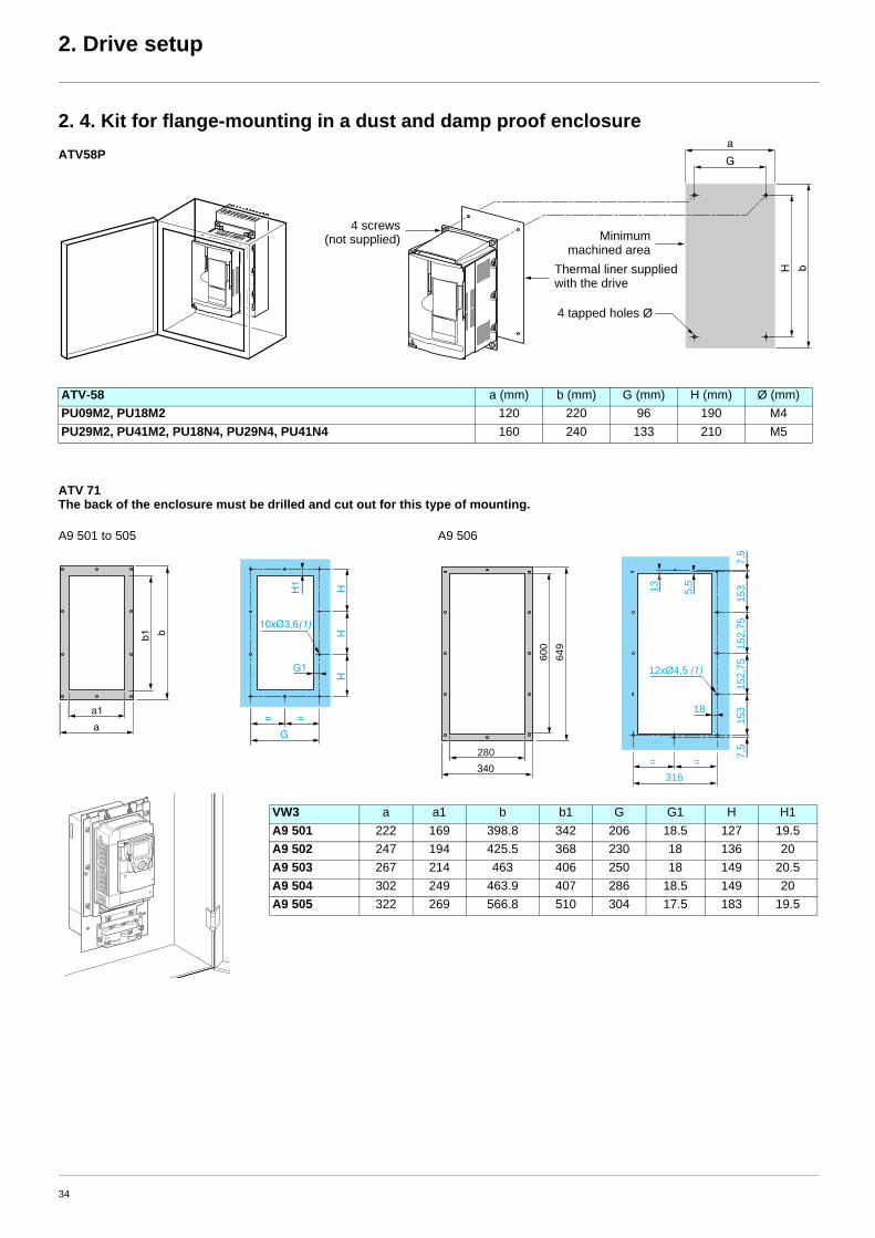
2. 4. Kit for flange-mounting in a dust and damp proof enclosure
ATV 71The back of the enclosure must be drilled and cut out for this type of mounting.
ATV-58 a (mm) b (mm) G (mm) H (mm) Ø (mm)PU09M2, PU18M2 120 220 96 190 M4PU29M2, PU41M2, PU18N4, PU29N4, PU41N4 160 240 133 210 M5
VW3 a a1 b b1 G G1 H H1A9 501 222 169 398.8 342 206 18.5 127 19.5A9 502 247 194 425.5 368 230 18 136 20A9 503 267 214 463 406 250 18 149 20.5A9 504 302 249 463.9 407 286 18.5 149 20A9 505 322 269 566.8 510 304 17.5 183 19.5
a
G
bH
4 screws(not supplied)
Thermal liner supplied with the drive
Minimummachined area
4 tapped holes Ø
ATV58P
a1
H1
HH
H
b
a
b1
G1
=
G
=
10xØ3,6(1)
280
5,5
13
153
153
7,5
7,5
152,
7515
2,75
649
340
12xØ4,5 (1)
600
=
18
=
316
A9 501 to 505 A9 506
34

2. Drive setup
2. 5. NEMA mounting kits Dimensions, in inches and (mm)
Kit catalognumber
Productsize
Drive catalog numberATV58Hppppp
a(in.)
b(in.)
c(in.)
G(in.)
H(in.)
Ø(in.)
d(lb.)
VW3A58851 1 U09M2, U18M2 4.45(113)
8.11(206)
6.58(167)
3.78(96)
7.48(190)
0.20(5)
2.62(66.7)
VW3A58852 2 U29M2, U41M2, U18N4, U29N4, U41N4 5.91(150)
9.06(230)
7.24(184)
5.20(133)
8.27(210)
0.20(5)
2.81(71)
VW3A58853 3 U54M2, U72M2, U54N4, U72N4, U90N4 6.89(175)
11.26(286)
7.24(184)
6.10(155)
10.63(270)
0.22(5.5)
2.94(75)
VW3A58854 4 U90M2, D12M2, D12N4, D16N4 9.06(230)
12.80(325)
8.27(210)
7.9(200)
12.20(310)
0.22(5.5)
2.94(75)
VW3A58855 5 D23N4 9.06(203)
16.35(415)
8.27(201)
7.9(200)
15.75(400)
0.22(5.5)
2.94(75)
Kit catalognumber
Productsize
Drive catalog numberATV58Hppppp
A(in.)
B(in.)
C(in.)
E(in.)
F(in.)
G(in.)
I(in.)
K(in.)
Ø(in.)
L(lb.)
VW3A58856 6 D16M2, D23M2, D25N4, D28N4, D33N4, D46N4
9.45(240)
21.65(550)
11.14(283)
5.57(146)
12.05(306)
8.07(205)
20.87(530)
0.39(10)
0.28(7)
3.5(89)
VW3A58857 7 D28M2, D33M2, D46M2, D54N4, D64N4, D79N4
13.78(350)
25.59(650)
11.97(304)
9.29(236)
15.35(390)
11.81(300)
24.37(619)
0.39(10)
0.36(9)
6.75(171)
a
G =
=H b
d
=
= c
KitKit
C
Kit Kit
35

2. Drive setup
Kit for UL NEMA Type 1 conformity or IP 21 protectionVW3 A9 ppp
VW3 a (in.) b (in.) VW3 a (in.) b (in.)
A9 101, 201 130 (5.12) 113 (4.45) A9 106, 206 240 (9.45) 185 (7.28)
A9 102, 202 155 (6.10) 103 (4.06) A9 107, 207 240 (9.45) 180 (7.09)
A9 103, 203 175 (6.89) 113 (4.45) A9 108, 208 320 (12.60) 178 (7.01)
A9 104, 204 210 (8.27) 113 (4.45)
A9 105, 205 230 (9.06) 108 (4.25)
VW3 a (in.) b (in.) c (in.) G (in.) K (in.) K1 (in.) K2 (in.) Ø (in.)
A9 109, 209 320 (12.60) 220 (8.66) 377 (14.84) 250 (9.84) 95 (3.74) 65 (2.56) 75 (2.95) 11.5 (0.45)
Δb
Drive
VW3 A9 xxxxx kit
a
c
b
a
b
VW3 A9 101…105, 201…205 VW3 A9 106…108, 206…208
G
K2
KK
1
4xØ
b
c
a
= =
VW3 A9 109…116, VW3 A9 209
36

2. Drive setup
2. 6. Separate control card power supply
2. 7. Remote display terminalUsed to connect the programming terminal remotely on the front of the enclosure.
Fixings: As the dimensions are not the same, the fixing holes must be modified.
This type of wiring is essential when using a VW3 A3 304 Interbus-S communication option card.
ATV58(F) ATV 71
A1ATV71Hppppp
P240V
+24 V
0 V
55,6 mm
24 mm
4 x 3,5 mm 36 mm
79,6
mm
52 m
m
115 mm (4.53 in)104 mm (4.09 in)
115
mm
(4.5
3 in
)10
0 m
m (3
.93
in)
5 m
m (0
.2 in
)
RUN
STOP
RESET
F2F1
F3 F4
ESC
FWD
REV
37

2. Drive setup
2. 8. Power wiringThe layout and type of power terminals have changed:
Ring terminals must be used rather than ferrules for the ground terminals, although for the power terminals the ferrules used previously canbe retained if they are in good condition (a flattened ferrule will not make a good connection).
Table of correspondence for power terminals
Disconnecting the RFI filter if using an IT system
Layout of the ATV58 power terminals
ATV58(F) ATV 71AC supply L1 R/L1
L2 S/L2L3 T/L3
DC bus + PO- PC/-
Braking resistor PA PA/+PB PB
Motor output U U/T1V V/T2W W/T3
Connecting to the Altivar 58 Connecting to the Altivar 71
IT system: Isolated or impedance grounded neutral.Use a permanent insulation monitor compatible with non-linear loads: a Merlin Gerin type XM200 or equivalent.
Altivar 71 drives feature built-in RFI filters. These filters can be isolated from ground for operation on an IT system as follows:Remove the jumper located to the left of the power terminals
t L1 L2 + - U V W t ATV-58•U09M2 and U18M2
t L1 L2 L3 PA PB U V W t ATV-58•U29M2 to D12M2 andATV-58•U18N4 to D23N24
t L1 L2 L3 + - PA PB U V W t ATV-58HD16M2X to D46M2X, ATV-58HD28N4 to D79N4 and ATV-58HD28N4X to D79N4
U
V
W
L1U
1
W1
V1
M 3 a
L2 L3A1
R2A
R2C
PA
PB
R1A
R1C
R1B
ATV58pppppp
Braking resistor(if used)
ATV71HpppM3
U /
T1
V /
T2
W /
T3
R /
L1
M 3 a
S /
L2
T / L
3A1
R1A
R1C
R1B
R2A
R2C
U1
W1
V1
PW
R
+24
P0
PA
/ +
PB
PC
/ -
Braking resistor(if used)
Normal(filter connected)
IT system(filter disconnected)
38
SESA61523
Power
SESA61523
wiring

2. Drive setup
Characteristics of the ATV58 power terminals
ATV58p Terminals Maximum wire size
Tightening torque
mm² AWG Nm(lb.in)
U09M2, U18M2 all 1.5 14 0.5U29M2, U14M2, U18N4U29N4, U41N4
all 6 8 0.75
U54M2, U72M2, U54N4U72N4, U90N4
all 6 8 0.75
U90M2, D112M2, D12N4D16N4, D23N4
all 10 6 2
ATV58H Terminals Maximum wire size
Tightening torque
mm² AWG Nm(lb.in)
D28N4, D28N4X PAPB 10 6 2
other 16 4 3D16M2X, D23M2XD23N4, D46N4D33N4X, D46N4X
PAPB 16 4 3
other 35 2 4D28M2X, D33M2X, D46M2XD54N4, D64N4, D79N4D54N4X, D64N4X, D79N4X
PAPB 35 2 4
other 70 2/0 10
39
SESA61523
U90N4

2. Drive setup
Layout of the ATV 71 power terminals and tightening torque
For ATV 71pppppp drives
For ATV 71pppppp drives
For ATV 71pppppp drives
PO PA/+ PB PC/-
U/T1 V/T2 W/T3R/L1 S/L2 T/L3
ATV 71H Maximum wire size
Tightening torque
mm² AWG Nm(lb.in)
037M3, 075M3, U15M3,075N4, U15N4, U22N4 2.5 14 1.2
(10.6)U22M3, U30M3, U40M3, U30N4, U40N4 6 8 1.2
(10.6)
PO PA/+ PB PC/- U/T1 V/T2 W/T3R/L1 S/L2 T/L3
ATV 71H Maximum wire size
Tightening torque
mm² AWG Nm(lb.in)
U55M3, U55N4, U75N4 10 6 2
(17.7)U75M3, D11N4 16 4 2.4
(21)D11M3X, D15M3X, D15N4, D18N4 35 1 2.4
(21)
PO PA/+ PB PC/-
U/T1 V/T2 W/T3R/L1 S/L2 T/L3
ATV 71H Maximum wire size
Tightening torque
mm² AWG Nm(lb.in)
D18M3X, D22M3X,D22N4, D30N4, D37N4 50 1/0 6
(53)
ATV 71H Maximum wire size
Tightening torque
mm² kcmils Nm(lb.in)
D30M3X, D37M3X, D45M3X, D45N4, D55N4, D75N4 120 350 19
(168)
40
SESA61523
For
SESA61523
ATV
SESA61523
71pppppp

2. Drive setup
Control wiring and I/O characteristics(Warning: Check the I/O assignment made by PowerSuite)
In order to ensure that the Altivar 71 works correctly, the following rules must be adhered to:
• Check that the SW1 switch on the Altivar 71 and the SW3 and SW4 switches on the option cards are in "Source" position.
• Check that the strap is present between +24 and PWR.
• The PTC probes connected on an ATV 71 correspond to market standards. Please note that the values are slightly different. Check that the trip thresholds are suitable for the temperature levels supported by the motor.
In PTC mode, Li6 is only taken into account after a Power on.
Control and option card logic input wiringControl card connection diagram
ATV58(F) value (kOhms) ATV 71 value (kOhms)Probe short-circuit 0.200 < 0.05Reset 1.5 1.8Overheat 2 3Probe break 20 > 100
R1B
R1A
R1C
R2A
R2C A
I1+
+10
AI1
-C
OM
AI2 CO
MA
O1
0VP24
LI1
LI2
LI3
LI4
LI5
LI6
+24
PW
R
RJ45
SW1
SW2 Ext
Source
SinkInt
SW3Ext
Source
SinkInt
SW4Ext
Source
SinkInt
VW3 A3 201
VW3 A3 202
ATV71HpppM3
PW
R
+24
A1 ATV71Hppppp
LI1
LI5
+24
0VLI3
LI2
LI6
LI4
41
SESA61523
Control
SESA61523
card
SESA61523
connection
SESA61523
diagram
2. Drive setup
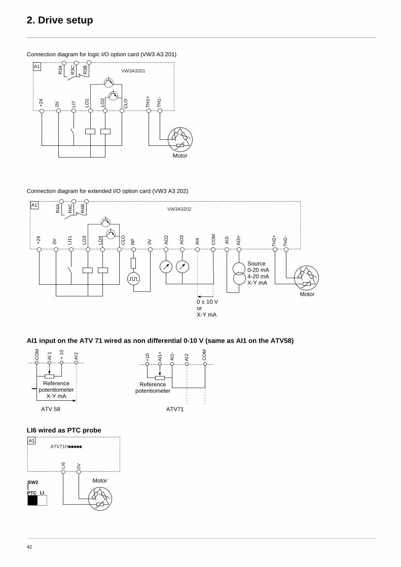
Connection diagram for logic I/O option card (VW3 A3 201)
Connection diagram for extended I/O option card (VW3 A3 202)
AI1 input on the ATV 71 wired as non differential 0-10 V (same as AI1 on the ATV58)
LI6 wired as PTC probe
+24
VW3A3201
CLOLO
2
LO1
LI7
0V TH1+
TH1-
R3A
R3C
R3BA1
Motor
+24
VW3A3202
0VRP
CLO
LO4
LO3
LI11
0V TH2+
TH2-
AO
2
AO
3
CO
M
AI4 AI3
-
AI3
+
R4A
R4C
R4BA1
Source0-20 mA4-20 mAX-Y mA
Motor0 ± 10 VorX-Y mA
CO
M
Al 1 AI2+ 10
+10
AI1
+
AI2AI1
-
CO
M
ATV 58 ATV71
Reference potentiometer
X-Y mA
Reference potentiometer
0VLI6
A1ATV71Hppppp
PTC LI
SW2 Motor
42

2. Drive setup
Wiring the VW3 A3 401 option card encoder input when replacing an ATV58FOn the Altivar 58F, encoder signals A A- or B B- had to be reversed in order to avoid the motor rotating in the wrong direction. This anomalyhas been corrected on the Altivar 71 and, therefore, the wiring conforms to the signal order A A- B B-.
ATV58F
ATV 71
The encoder card’s connector does not have a terminal for connecting the cable shielding.
This shielding must, therefore, be connected to the power terminals; use a tag connector or an accessory: D23 FA3.
0 V
5 V
A A- B B-
A A-
B B-
0 V
5 V
0 V
5 V
A A- B B-
A A-
B B-
0 V
5 V
Encoder Encoder
OR
A A- B B-
A A-
B B-
0 V
s
+ V
s
0 V
s
+ V
s
VW3 A3 40p
Encoder
PO PA/+ PB PC/- U/T1 V/T2 W/T3R/L1 S/L2 T/L3
43

3. Setup for the Altivar 71 communication option cards
3. 1. GeneralReceiptCheck that the card catalog number marked on the label is the same as that on the delivery note corresponding to the purchase order.Remove the option card from its packaging and check that it has not been damaged in transit.
Check that the drive is turned off. Check that there is no voltage on the DC bus: Red LED (POWER) off, wait for 3 minutesafter turning off the drive.
Installing the communication option card See Installation Manual pages 16 and 17.
When migrating an Altivar 58(F) installation to Altivar 71, the PowerSuite v2.20 program must be used to configure the ATV71 in 8 seriemode in order to ensure absolute consistency of the communication, drive and adjustment parameters between the two drive ranges.However, for some communications options, one or more of the microswitches on the card have to be toggled manually.
The connector for connecting the option card to the communication bus is not the same on the Altivar 71. This is now on the top right-handside of the drive.You should, therefore, make sure that the cable(s) is(are) long enough to make this connection.
If necessary, you should do one of the following:- Reconnect the wiring up and/or downstream of the drive- Adjust the drive position- Use an extension cable
ATV 71H 037M3 to D15M3Xand ATV 71 075N4 to D18N4
ATV 71H D18M3 to D45M3X and ATV 71H D22N4 to D75N4
Red LED indicating that the DC bus is turned on.
44

3. Setup for the communication option cards
Option card faultThe [internal com. link] (ILF-) fault appears when the following serious problems occur:
- Hardware fault on the option card- Dialog fault between the option card and the drive
The [Internal link fault 1] (ILF1) diagnostic parameter can be used to obtain more detailed information about the origin of the last[internal com. link] (ILF) fault:
This parameter can be accessed on the graphic display terminal only, in the [1.10 DIAGNOSTICS] (DGt-) menu,[MORE FAULT INFO] (AFI-).
• When the External Fault function is used via a communication card, the Altivar 58(F) would display EPF, but the Altivar 71 now displays EPF2.
• When the Fast Stop function is used via a communication card, the Altivar 58(F) would display RDY, but the Altivar 71 now displays FST.
• It is essential to follow the Altivar 58(F) internal variables manual when the Altivar 71 is being used in 8 serie mode. If not, migration may not proceed smoothly.
Value Description of parameter values Value Description of parameter values
0 No fault 8 Faulty analog input
1 Loss of internal communication with the drive 9 Faulty analog output
2 Hardware fault detected 10 Faulty logic input
3 Error in the EEPROM checksum 11 Faulty logic output
4 Faulty EEPROM 101 Unknown card
5 Faulty Flash memory 102 Exchange problem on the drive internal bus
6 Faulty RAM memory 103 Time out on the drive internal bus (500 ms)
7 Faulty NVRAM memory
45

3. Setup for the communication option cards
3. 2. Communication via Modbus network3. 2. 1. Calculating the polarization resistorsMixed schematic Slaves with 4.7 kΩ polarization can be integrated into a standard schematic. Suitable polarization resistance (Rp) must be calculated.
Schematic diagram
• To calculate the polarization resistance (Rp), all station polarizations must be deemed to be connected in parallel.
ExampleIf the bus Rp polarization is 470 Ω (installed in the master) and 2 slaves have 4700 Ω polarization, the equivalent polarization is:1/Re = 1/470 + 1/4700 + 1/4700i.e., Re = 1/ (1/470 + 1/4700 + 1/4700)and, therefore, Re = 390 Ω390 Ω is greater than 162 Ω, and the schematic is correct.
For an ideal equivalent polarization (650 Ω), Rp bus polarization can be installed so that:1/650 = 1/Rp + 1/4700 + 1/4700,i.e., Rp = 1/(1/650 – 1/4700 – 1/4700)and, therefore, Rp = 587 Ω.
• If the master has 470 Ω polarization, up to 18 slaves with 4.7 kΩ polarization can be connected.
Type of trunk cable Shielded cable with 1 twisted pair and at least a 3rd conductor Maximum length of bus 1000 m at 19200 bpsMaximum number of stations (without repeater) Up to 32 stations, i.e., 31 slaves (depending on Rp and the number of 4.7 kΩ resistors)Maximum length of tap links • 20 m for a single tap link
• 40 m divided by the number of tap links on a multiple junction boxBus polarization • One pulldown resistor at the 5 V (Rp)
• One pulldown resistor at the Common (Rp)This polarization can be provided in the master.The value of Rp should be validated (or determined) by calculating the equivalent polarization (Re) according to the polarization of the master and slave stations.The value of Re must be between 162 Ω and 650 Ω (recommended value: 650 Ω).
Line termination One 120 Ω 0.25 W resistor in series with a 1 nF 10 V capacitorCommon polarity Yes (Common)
1 nF
4,7 kΩ4,7 kΩ
Rp
Rp
120 Ω
5 V
0 V
5 V
0 V
D1
Common
D0
R T
TR
TR
Master
Slave 1 Slave n
46

3. Setup for the communication option cards
3. 2. 2. Reminder of the various connection methods:
ATV 71 RJ45 connector on TSXSCA50 or other screw terminals: Use cable VW3 A8 306 D30 (RJ45 to stripped end, 3 meters)
ATV 71 RJ45 connector on TSXSCA62: Use cable VW3 A8 306 (RJ45 to 15-way Sub-D)
3. 2. 2. 1. Configuring the driveThere are two possible scenarios.
Scenario 1 Using the built-in port when replacing the VW3A58303 Modbus/Unitelway option cardAs the PowerSuite software workshop is not able to anticipate this scenario, the communication, address and protocol-format parametersmust be entered manually:
Configuring the addressTransfer the Altivar 58 parameters to the Altivar 71 using the integrated display terminal, the graphic display terminal or the PowerSuitesoftware workshop:
The configuration of the Modbus network parameters can be accessed via the [MODBUS NETWORK] ( Md I-) submenu in the [1.9 – COMMUNICATION] ( COM -) menu.
Configuring the drive control modeCheck and configure the control mode applied to the drive in the [1.6 – COMMAND] (CtL-) menu on the graphic display terminal,the integrated display terminal or the PowerSuite software workshop,
[Profile] (CHCF) = [8 serie] (SE8)
2 = 0 V – brown t 0VL 0VL D(A) D(B) 2 = 0 V3 = D_B – blue 1 2 3 4 5 4 = D_A5 = D_A – white/blue 5 = D_B
2 = 0 V – brown 15 = 0 V3 = D_B – blue 14 = D_A5 = D_A – white/blue 7 = D_B
Modbus parameter Description/Possible values Terminal display Default value
[Modbus Address] (Add) 1 to 247Drive Modbus disabled (0)
[1] (1) to [247] (247) [Off] (OFF)
[Modbus baud rate] (tbr) 4800 bps
9600 bps
19200 bps
38400 bps
[4.8 Kbps] ( 4 8)
[9.6 Kbps] ( 9 6)
[19.2 Kbps] ( 19 2)
[38.4 Kbps] ( 38 4)
[19200] ( 19 2)
[Modbus format] (tFO) 8 data bits, odd parity, 1 stop bit
8 data bits, even parity, 1 stop bit
8 data bits, no parity, 1 stop bit
8 data bits, no parity, 2 stop bits
[8-0-1] (8o1)
[8-E-1] (8E1)
[8-N-1] (8n1)
[8-N-2] (8n2)
[8 E 1] (8E1)
8........................1
8........................1
1 2 3 4 5 6 7 8
1514131211109
47

3. Setup for the communication option cards
Configuring communication monitoringSince the Altivar 58’s communication monitoring time out is the same as the default value of the Altivar 71’s [Modbus time out] (ttO)field (10 s), there is no point in modifying the value of this field.
Modification of these parameters will only take effect on the next power-up.
After transfer of the drive configuration by the PowerSuite software workshop, the [Channel switching] (CHCF) parameter isautomatically assigned to [8 serie] (SE8), thus providing access to memory mapping for the Altivar 58 compatible with the Altivar 71.
PLC configuration and applicationThe fact of opening the Altivar 71’s "ATV58(F) compatibility" memory zone (SE8 mode) means that no changes need to be made in thePLC application.
However, in response to a function 43 identification request (16#2B) the drive will identify itself as an Altivar 71, not an Altivar 58(F).
Scenario 2 Using the built-in port when replacing the ATV58 terminal port
Configuring the driveThis example is implemented in the PowerSuite software workshop and consequently all the settings linked to the configuration parameters(address, baud rate, parity) will be assigned automatically, identical to the Altivar 58.
Configuring communication monitoringSince the Altivar 58’s communication monitoring time out is the same as the default value of the Altivar 71’s [Modbus time out] (ttO)field (10 s), there is no point in modifying the value of this field.
Modification of these parameters will only take effect on the next power-up.
PLC configuration and applicationThe fact of opening the Altivar 71’s "ATV58(F) compatibility" memory zone (SE8 mode) means that no changes need to be made in thePLC application.
However, in response to a function 43 identification request (16#2B) the drive will identify itself as an Altivar 71, not an Altivar 58(F).
48

3. Setup for the communication option cards
3. 3. Communication via Unitelway/Modbus network and VW3 A3 303 option card3. 3. 1. Reminder of possible connection methods
If the chosen communication interface is the VW3 A3 303 option card (Modbus RTU/Jbus/Ascii, Unitelway) both the address and theprotocol format must be configured manually.
3. 3. 2. Configuring the drive address on the Modbus/Unitelway networkTransfer the Altivar 58 address to the Altivar 71:An Altivar 58(F) was identified on the bus by its address, coded between 0 and 31.
The address corresponds to the number represented by the binary value 1 or 0 of the 8 card switches(in fact only micro-switches 3 to 7 are used).
The least significant bits are on the right.
Transfer the Altivar 58 address to the Altivar 71 using the 8 switches on the right of the card; the value 0 being the OFF position,the value 1 the ON position.The least significant bits are on the right.
On the Altivar 58, the binary value 1 of a switch is in the up position, on the Altivar 71 this position is reversed, and the value 1 is effectivein the down position.
Example
Use of address 0 is not recommended on a Modbus/Unitelway network as this address has the effect of deactivating the option card.
ATV58(F) ATV 71
3 = D(A)4 = 0 V7 = D(B)
3 = D(A)4 = 0 V7 = D(B)
ATV58(F) ATV 71
Address 11 = 2#0001011 Address 11 = 2#0001011
Address ATV58(F) switches ATV71 switches Address ATV58(F) switches ATV71 switches12345678 12345678 12345678 12345678
0 0000 0000 0000 0000 16 0010 0000 0001 00001 0000 0010 0000 0001 17 0010 0010 0001 00012 0000 0100 0000 0010 18 0010 0100 0001 00103 0000 0110 0000 0011 19 0010 0110 0001 00114 0000 1000 0000 0100 20 0010 1000 0001 01005 0000 1010 0000 0101 21 0010 1010 0001 01016 0000 1100 0000 0110 22 0010 1100 0001 01107 0000 1110 0000 0111 23 0010 1110 0001 01118 0001 0000 0000 1000 24 0011 0000 0001 10009 0001 0010 0000 1001 25 0011 0010 0001 100110 0001 0100 0000 1010 26 0011 0100 0001 101011 0001 0110 0000 1011 27 0011 0110 0001 101112 0001 1000 0000 1100 28 0011 1000 0001 110013 0001 1010 0000 1101 29 0011 1010 0001 110114 0001 1100 0000 1110 30 0011 1100 0001 111015 0001 1110 0000 1111 31 0011 1110 0001 1111
49

3. Setup for the communication option cards
3. 3. 3. Configuring polarity on the drive RS 485 busThe card is equipped with 2 line polarity configuration switches but the orientation is not the same for the Altivar 58 and the Altivar 71.Configure the polarity according to the following method.
Configuring the drive control modeCheck and configure as necessary the control mode applied to the drive in the [1.6 – COMMAND] (CtL-) menu on the graphic displayterminal, the integrated display terminal or the PowerSuite software workshop.[Profile] (CHCF) = [8 serie] (SE8)
3. 3. 4. PLC configuration and applicationThe fact of opening the Altivar 71’s "ATV58(F) compatibility" memory zone (SE8 mode) performed by the PowerSuite software workshopmeans that no changes need to be made in the PLC application.However, in response to a function 43 identification request (16#2B) the drive will identify itself as an Altivar 71, not an Altivar 58(F).
3. 4. Communication via CANopen network3. 4. 1. Reminder of possible connection methods
The ATV71 CANopen adapter must be used when connecting the Altivar 71 to a CANopen network.
3. 4. 2. Matching the line termination resistorThe VW3 CAN KCDF 180T connector for connecting to the CANopen bus incorporates a line termination resistor. You should ensure thishas been activated when the drive is at the end of the trunk cable.
ATV58(F) ATV 71
Unitelway protocol
Modbus/Jbus protocol
ATV58(F) ATV 71
1 = CAN_GND2 = CAN_L4 = CAN_H
2 = CAN_L3 = CAN_GND7 = CAN_H
Example: ATV71HU22M3ATV71
CANopenadapter
50

3. Setup for the communication option cards
3. 4. 3. Configuring the driveOn the Altivar 58’s CANopen communication option card, both addresses and the bus speed could be set via switches.
The PowerSuite software workshop is not capable of configuring the Altivar 71 automatically since these parameters were not stored in theAltivar 58 but in the option card.
The Altivar 71 parameters should, therefore, be set via the programming terminal, and where the product is being migrated, the PowerSuitesoftware workshop is responsible for configuring the drive so that it is identical to the configuration that existed on the Altivar 58.
3. 4. 4. Address and Baud rateConfiguration of the Altivar 71’s CANopen communication functions is accessed via the [CANopen] (CnO-) submenu in the[1.9 – COMMUNICATION] (COM-) menu on the graphic display terminal, integrated display terminal or the PowerSuitesoftware workshop.
The configuration can only be modified when the motor is stopped and the drive locked (no run command present).In order for modifications to take effect, the drive must be shut down then restarted.
3. 4. 5. PLC configuration and applicationThe fact of opening the Altivar 71’s "ATV58(F) compatibility" memory zone (SE8 mode) performed by the PowerSuite software workshopmeans that no changes need to be made in the PLC application.
In fact, the PDO used by default in the Altivar 71 in 8 serie mode is PDO1 type and is, therefore, compatible with that in the Altivar 58.
Configuring the drive control modeCheck and configure the control mode applied to the drive in the [1.6 – COMMAND] (CtL-) menu on the graphic display terminal,the integrated display terminal or the PowerSuite software workshop.
[Profile] (CHCF) = [8 serie] (SE8)
Parameter Possible values Terminal display Default value[CANopen address] (AdCO) 0 to 127 [0] (0) to [127] (127) 0
[CANopen bit rate] (bdCO) 50 kbps [50 kbps] (50)
125 kbps [125 kbps] (125) 125 kbps
250 kbps [250 kbps] (250)
500 kbps [500 kbps] (500)
1000 kbps [1 Mbps] (1M)
51

3. Setup for the communication option cards
3. 5. Communication via Profibus DP network3. 5. 1. Reminder of the possible connection methods: Same as existing
3. 5. 2. Configuring the drive address on the Profibus DP networkWith the Altivar 58’s VW3-A58307 Profibus DP option card, the drive address was coded via the programming terminal. You need, therefore,to use this terminal to find this address before turning off the drive and replacing it.
Transfer the Altivar 58 address to the Altivar 71 using the 7 switches on the right of the card; the value 0 being the OFF position, the value 1the ON position.
Example
If the PLC module was configured using the Sycon < v2.8 configuration tool, it was possible to use address 126 for a subscriber(Altivar or other).This address is reserved and, therefore, its use is prohibited from version v2.8 onwards in accordance with the recommendationsof the Profibus consortium.
3 = Rx/Tx- 5 = GND
6 = VP8 = Rx/Tx+
Address 23 Address 89
Address Switches Address Switches Address Switches Address Switches1234 5678 1234 5678 1234 5678 1234 5678
0 1000 0000 32 1010 0000 64 1100 0000 96 1110 00001 1000 0001 33 1010 0001 65 1100 0001 97 1110 00012 1000 0010 34 1010 0010 66 1100 0010 98 1110 00103 1000 0011 35 1010 0011 67 1100 0011 99 1110 00114 1000 0100 36 1010 0100 68 1100 0100 100 1110 01005 1000 0101 37 1010 0101 69 1100 0101 101 1110 01016 1000 0110 38 1010 0110 70 1100 0110 102 1110 01107 1000 0111 39 1010 0111 71 1100 0111 103 1110 01118 1000 1000 40 1010 1000 72 1100 1000 104 1110 10009 1000 1001 41 1010 1001 73 1100 1001 105 1110 100110 1000 1010 42 1010 1010 74 1100 1010 106 1110 101011 1000 1011 43 1010 1011 75 1100 1011 107 1110 101112 1000 1100 44 1010 1100 76 1100 1100 108 1110 110013 1000 1101 45 1010 1101 77 1100 1101 109 1110 110114 1000 1110 46 1010 1110 78 1100 1110 110 1110 111015 1000 1111 47 1010 1111 79 1100 1111 111 1110 111116 1001 0000 48 1011 0000 80 1101 0000 112 1111 000017 1001 0001 49 1011 0001 81 1101 0001 113 1111 000118 1001 0010 50 1011 0010 82 1101 0010 114 1111 001019 1001 0011 51 1011 0011 83 1101 0011 115 1111 001120 1001 0100 52 1011 0100 84 1101 0100 116 1111 010021 1001 0101 53 1011 0101 85 1101 0101 117 1111 010122 1001 0110 54 1011 0110 86 1101 0110 118 1111 011023 1001 0111 55 1011 0111 87 1101 0111 119 1111 011124 1001 1000 56 1011 1000 88 1101 1000 120 1111 100025 1001 1001 57 1011 1001 89 1101 1001 121 1111 100126 1001 1010 58 1011 1010 90 1101 1010 122 1111 101027 1001 1011 59 1011 1011 91 1101 1011 123 1111 101128 1001 1100 60 1011 1100 92 1101 1100 124 1111 110029 1001 1101 61 1011 1101 93 1101 1101 125 1111 110130 1001 1110 62 1011 1110 94 1101 1110 126 0111 111031 1001 1111 63 1011 1111 95 1101 1111
52
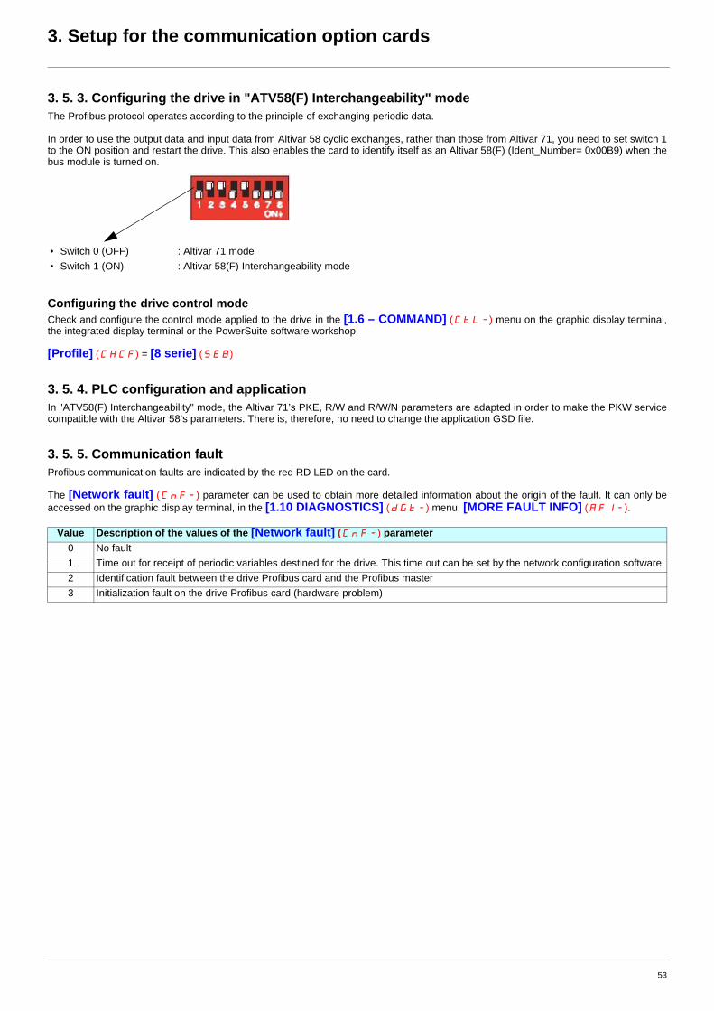
3. Setup for the communication option cards
3. 5. 3. Configuring the drive in "ATV58(F) Interchangeability" modeThe Profibus protocol operates according to the principle of exchanging periodic data.
In order to use the output data and input data from Altivar 58 cyclic exchanges, rather than those from Altivar 71, you need to set switch 1to the ON position and restart the drive. This also enables the card to identify itself as an Altivar 58(F) (Ident_Number= 0x00B9) when thebus module is turned on.
Configuring the drive control modeCheck and configure the control mode applied to the drive in the [1.6 – COMMAND] (CtL-) menu on the graphic display terminal,the integrated display terminal or the PowerSuite software workshop.
[Profile] (CHCF) = [8 serie] (SE8)
3. 5. 4. PLC configuration and applicationIn "ATV58(F) Interchangeability" mode, the Altivar 71’s PKE, R/W and R/W/N parameters are adapted in order to make the PKW servicecompatible with the Altivar 58’s parameters. There is, therefore, no need to change the application GSD file.
3. 5. 5. Communication faultProfibus communication faults are indicated by the red RD LED on the card.
The [Network fault] (CnF-) parameter can be used to obtain more detailed information about the origin of the fault. It can only beaccessed on the graphic display terminal, in the [1.10 DIAGNOSTICS] (dGt-) menu, [MORE FAULT INFO] (AFI-).
• Switch 0 (OFF) : Altivar 71 mode• Switch 1 (ON) : Altivar 58(F) Interchangeability mode
Value Description of the values of the [Network fault] (CnF-) parameter0 No fault1 Time out for receipt of periodic variables destined for the drive. This time out can be set by the network configuration software.2 Identification fault between the drive Profibus card and the Profibus master3 Initialization fault on the drive Profibus card (hardware problem)
53

3. Setup for the communication option cards
3. 6. Communication via Fipio network – VW3 A3 301 option card3. 6. 1. Reminder of the possible connection methods: Same as existing
3. 6. 2. PresentationThe VW3 A3 301 Fipio communication card, compatible with Altivar 58(F), can be used to connect an Altivar 71 drive, with software versionie 03 or higher, to a Fipio network. Its functions have been designed specifically for configuration transfer and drive control by means ofperiodic data. The message handling service is not installedYou can check the Altivar 71 software version via the graphic display terminal [1.11 – IDENTIFICATION] menu, Appli Software VxxIE03
It is only designed for replacement of an Altivar 58(F) equipped with a VW3-A58301 Fipio card.
3. 6. 3. Connecting to the Fipio busIf the tap junction connector used with the Altivar 58 is a TSX FP ACC12 connector, no restrictions are imposed when replacing anAltivar 58(F) with an Altivar 71.
3. 6. 4. Configuring the drive address on the Fipio networkExample
Note: Addresses 0 and 63 must not be used on an Altivar 58(F) or an Altivar 71.
6 = Tx+ 7 = Tx-
TSX FP ACC2connectorwith wiring on the right.
If this tap junction connector is a TSX FP ACC2, the Fipio cables and/or the TSX FP ACC7 line terminator must be located on this tap junction connector onthe side indicated opposite.
This involves modifying the internal connections to the tap junction connector, and it is possible that this may pose new problems concerning cable length(s), see General, page 44.
Address 11: 2#001011 Address 34: 2#100010
Address Switches Address Switches Address Switches Address Switches1234 5678 1234 5678 1234 5678 1234 5678
0 0000 0000 16 0001 0000 32 0010 0000 48 0011 00001 0000 0001 17 0001 0001 33 0010 0001 49 0011 00012 0000 0010 18 0001 0010 34 0010 0010 50 0011 00103 0000 0011 19 0001 0011 35 0010 0011 51 0011 00114 0000 0100 20 0001 0100 36 0010 0100 52 0011 01005 0000 0101 21 0001 0101 37 0010 0101 53 0011 01016 0000 0110 22 0001 0110 38 0010 0110 54 0011 01107 0000 0111 23 0001 0111 39 0010 0111 55 0011 01118 0000 1000 24 0001 1000 40 0010 1000 56 0011 10009 0000 1001 25 0001 1001 41 0010 1001 57 0011 100110 0000 1010 26 0001 1010 42 0010 1010 58 0011 101011 0000 1011 27 0001 1011 43 0010 1011 59 0011 101112 0000 1100 28 0001 1100 44 0010 1100 60 0011 110013 0000 1101 29 0001 1101 45 0010 1101 61 0011 110114 0000 1110 30 0001 1110 46 0010 1110 62 0011 111015 0000 1111 31 0001 1111 47 0010 1111 63 0011 1111
54

3. Setup for the communication option cards
3. 6. 5. Configuring the drive in "ATV58(F) Interchangeability" modeThis card has been designed exclusively for replacement of an Altivar 58(F), hence the "ATV58(F) interchangeability" mode is implicit and,therefore, no switch needs to be activated on the card.
Configuring the drive control modeConfigure the control mode applied to the drive in the [1.6 – COMMAND] (CtL-) menu on the graphic display terminal, the integrateddisplay terminal or the PowerSuite software workshop.[Profile] (CHCF) = [8 serie] (SE8) before installing the option card, otherwise an EPF2 fault will appear.
The PowerSuite software workshop will activate 8 serie mode once the configuration has been transferred to the drive.
3. 6. 6. PLC configuration and applicationIn PL7 or Unity, the drive configuration remains the same as that of the original Altivar 58. Any configuration parameters that no longer existin the Altivar 71 are nonetheless accepted in write mode (positive report) or read-only mode (the current value is returned).
3. 6. 7. Restrictions and incompatibilitiesBits 11, 12 and 13 of monitoring parameter %IW\p.2.c\0.0.3 (IOLR) are now reserved bits (inactive). As a result, the following data is no longer available:
• Image of the red LED (%IW\p.2.c\0.0.3 :X11)• Image of the charge relay (%IW\p.2.c\0.0.3 :X12)• Image of the braking transistor (%IW\p.2.c\0.0.3 :X13)
Bits 0 and 15 of monitoring parameter %IW\p.2.c\0.0.6 (DF1) are now reserved bits (inactive). As a result, the following data is no longer available:
• "Incorrect calibration constants (INF)" fault• "Charge relay command loss (CRF)" fault• The adjustment ranges of parameters IBR, IDC and UFR are different for the Altivar 58(F) and the Altivar 71. These values vary according
to the rating of each drive. Make sure, therefore, that you adapt the value of these parameters. Otherwise, the PL7 Pro software workshop will display an error message.
• SPC parameter: It is essential to set parameter OPL to NO so that SPC can be modified. Otherwise, the PL7 Pro software workshop will display an error message.
• SFR parameter: The Altivar 58 accepted the value 0.5 kHz; this value is not compatible with the Altivar 71, whose minimum value is 1 kHz. Make sure, therefore, that you modify the value of SFR, otherwise the PL7 Pro software workshop will display an error message.
• CFG parameter: An Altivar 58(F) can only be replaced with an Altivar 71 when used in constant torque applications. As a result the assignment CFG = VT is prohibited; use a drive from the Altivar 61 range.
• TFR parameter: The Altivar 58 equipped with a VW3 A58301 Fipio card had a particular type of operation.It was possible for the value of the HSP parameter to be higher than that of the TFR parameter.This is no longer the case with the Altivar 71, which adopts a pedestal value for HSP. Make sure, therefore, that you adapt the value of these parameters. Otherwise, the PL7 Pro or Unity software workshop will display an error message.
3. 6. 8. Managing loss of Fipio communicationThe Altivar 71 VW3 A3 301 Fipio card, compatible with the Altivar 58(F), will respond to loss of communication with the Fipio master in thesame way as the Altivar 58 VW3-A58301 Fipio card:
When the drive is disconnected from the Fipio bus, the CNF fault is not activated and the motor will stop on a ramp.
3. 6. 9. Communication faultFipio communication faults are indicated by the red RD LED on the card.
The [Network fault] (CnF-) parameter can be used to obtain more detailed information about the origin of the fault. It can only beaccessed on the graphic display terminal, in the [1.10 DIAGNOSTICS] (dGt-) menu, [MORE FAULT INFO] (AFI-).
Value Description of the values of the [Network fault] (CnF-) parameter0 No fault1 Initialization fault on the Fipio card (hardware problem)2 Time out for receipt of periodic variables destined for the drive. This time out can be set by the network configuration software.3 Hardware fault on the Fipio card4 Hardware fault on the Fipio card5 Master PLC changes from Run to STOP
55

3. Setup for the communication option cards
3. 7. Communication via Fipio network – VW3 A3 311 option card3. 7. 1. Reminder of the possible connection methods: Same as existing
3. 7. 2. PresentationThe VW3 A3 311 Fipio communication card is used to connect an Altivar 71 drive to a Fipio network in place of an Altivar 58(F). Its functionsare dedicated to transferring both periodic and aperiodic data by means of a message handling service.
It is designed to replace an Altivar 58(F) equipped with a VW3-A58311 Fipio card.
3. 7. 3. Connecting to the Fipio busIf the tap junction connector used with the Altivar 58 is a TSX FP ACC12 connector, no restrictions are imposed when replacing anAltivar 58(F) with an Altivar 71.
3. 7. 4. Configuring the drive address on the Fipio networkExamples
Note: Addresses 0 and 63 must not be used on an Altivar 58(F) or an Altivar 71.
6 = Tx+ 7 = Tx-
TSX FP ACC2 connectorwith wiring on the right.
If this tap junction connector is a TSX FP ACC2, the Fipio cables and/orthe TSX FP ACC7 line terminator must be located on this tap junctionconnector on the side indicated opposite.
This involves modifying the internal connections to the tap junction connector, and it is possible that this may pose new problems concerning cable length(s), see General, page 44.
Address 11: 2#001011 Address 34: 2#100010
Address Switches Address Switches Address Switches Address Switches1234 5678 1234 5678 1234 5678 1234 5678
0 0000 0000 16 0001 0000 32 0010 0000 48 0011 00001 0000 0001 17 0001 0001 33 0010 0001 49 0011 00012 0000 0010 18 0001 0010 34 0010 0010 50 0011 00103 0000 0011 19 0001 0011 35 0010 0011 51 0011 00114 0000 0100 20 0001 0100 36 0010 0100 52 0011 01005 0000 0101 21 0001 0101 37 0010 0101 53 0011 01016 0000 0110 22 0001 0110 38 0010 0110 54 0011 01107 0000 0111 23 0001 0111 39 0010 0111 55 0011 01118 0000 1000 24 0001 1000 40 0010 1000 56 0011 10009 0000 1001 25 0001 1001 41 0010 1001 57 0011 100110 0000 1010 26 0001 1010 42 0010 1010 58 0011 101011 0000 1011 27 0001 1011 43 0010 1011 59 0011 101112 0000 1100 28 0001 1100 44 0010 1100 60 0011 110013 0000 1101 29 0001 1101 45 0010 1101 61 0011 110114 0000 1110 30 0001 1110 46 0010 1110 62 0011 111015 0000 1111 31 0001 1111 47 0010 1111 63 0011 1111
56

3. Setup for the communication option cards
3. 7. 5. Configuring the drive in "ATV58(F) Interchangeability" modeIn order to use the Altivar 58(F)’s periodic input/output variables rather than those of the Altivar 71, you need to set switch 1 to the ONposition and restart the drive.
The PowerSuite software workshop will activate 8 serie mode once the configuration has been transferred.
Configuring the drive control modeCheck and configure as necessary the control mode applied to the drive in the [1.6 – COMMAND] (CtL-) menu on the graphic displayterminal, the integrated display terminal or the PowerSuite software workshop.• [Profile] (CHCF) = [8 serie] (SE8)
3. 7. 6. PLC configuration and applicationIn the TSX Premium master’s Fipio configurator, the three base modules described in the table below are compatible with an Altivar 71 usedin 8 serie mode.
3. 7. 7. Altivar 58 PKW indexed periodic variablesIn "ATV58(F) Interchangeability" mode, we do not recommend using the PKW service for the Altivar 71 indexed periodic variables, as thisservice is only designed for accessing the Altivar 71 parameters.
You should, therefore, use the PKW service for the Altivar 58 indexed periodic variables, as described in the User’s Manual for the Altivar 58VW3-A58311 Fipio card. This service can be used to access only the Altivar 58 parameters.
3. 7. 8. Managing loss of Fipio communicationIn order to imitate the Altivar 58’s behavior on disconnection of the bus ("stop on ramp" imposed by the drive), you should configure it usingthe integrated display terminal or the graphic display terminal.
In the [COMMUNICATION FAULTS] (COF-) submenu in the [1.8 – FAULT MANAGEMENT] (FLt-) menu, assign thevalue [ramp] (rMP) to the [Com Bus Flt Mgt] (CLL) parameter, which is used to imitate the Altivar 58’s behavior on disconnectionof the Fipio bus.
Hence, when the drive is disconnected from the Fipio bus, the CNF fault will be activated and the value of parameter CLL will cause themotor to stop on a ramp.
3. 7. 9. Communication faultFipio communication faults are indicated by the red RD LED on the card.
The [Network fault] (CnF-) parameter can be used to obtain more detailed information about the origin of the fault. It can only beaccessed on the graphic display terminal, in the [1.10 DIAGNOSTICS] (dGt-) menu, [MORE FAULT INFO] (AFI-).
Family Base moduleATV-58 ATV58 PKWATV-58F ATV58F PKWSTD_P FED C32
Value Description of the values of the [Network fault] (CnF-) parameter0 No fault1 Initialization fault on the Fipio card (hardware problem)2 Time out for receipt of periodic variables destined for the drive. This time out can be set by the network configuration software.3 Hardware fault on the Fipio card4 Hardware fault on the Fipio card5 Master PLC changes from Run to STOP
• Switch 0 (OFF) : Altivar 71 mode• Switch 1 (ON) : 8 serie mode
57

3. Setup for the communication option cards
3. 8. Communication via Interbus network3. 8. 1. Reminder of the possible connection methods: Same as existing
The profile used by the Altivar 71 in the CMD Tool bus configurator is compatible with that of the Altivar 58, i.e., DRIVECOM TypeProfil 21 (RB) and, therefore, there is no difference in the process data.
Use the Altivar 71 control card’s external power supply function, as in the event of a break in the drive power supply allcommunication on the Interbus-S bus will cease.
3. 8. 2. Configuring the communication parametersThe drive is configured by default to communicate on the bus with limited services. The data exchanged on the bus is not transmitted to the drive.
On the display terminal, in the [1.9 COMMUNICATION] (COM-) menu, [COMMUNICATION CARD] (CBD-) submenu,the value of the [Address] (AdrC) parameter is 0.
To operate in normal mode, in which the data exchanged on the bus is transmitted to the drive by the INTERBUS card, the value of this[Address] (AdrC) parameter must be changed to 1.
Configuring the drive control modeCheck and configure the control mode applied to the drive in the [1.6 – COMMAND] (CtL-) menu on the graphic display terminal,the integrated display terminal or the PowerSuite software workshop.
[Profile] (CHCF) = [8 serie] (SE8)
3. 8. 3. PLC configuration and applicationThe fact of opening the Altivar 71’s "ATV58(F) compatibility" memory zone (SE8 mode) performed by the PowerSuite software workshopmeans that no changes need to be made in the PLC application.
However, in response to an "Identify" service request the drive will identify itself as an Altivar 71, not an Altivar 58(F).
1 = DO22 = DI23 = GNDO
4 = NC5 = VCCO6 = DO2/
7 = DI28 = NC9 = RBST
58

3. Setup for the communication option cards
3. 9. Communication via Modbus Plus network3. 9. 1. Reminder of the possible connection methods: Same as existing
3. 9. 2. Configuring the drive address on the Modbus Plus networkOn the Altivar 58’s Modbus Plus option card, the drive address is coded using switches 1 to 6 (LSB to MSB).
Therefore, simply transfer the switch configuration of a Modbus Plus option card for Altivar 58(F) to the switches of a Modbus Plus optioncard for Altivar 71.
The address corresponds to the binary number given by position 0 or 1 of the 6 switches increased by 1.
Example: address 6 = 5 (+1)
3. 9. 3. Configuring the drive in "ATV58(F) Interchangeability" modeIn order to use the Altivar 58(F) Peer Cop and Global Data variables rather than those of the Altivar 71, you need to set the right-hand switchto the ON position and restart the drive.
• Switch 0 (OFF): Altivar 71 mode• Switch 1 (ON): 8 serie mode
1 = GND2 = Tx3 = Rx
ATV58(F) ATV 71
Address Switches Address Switches Address Switches Address Switches1234 5678 1234 5678 1234 5678 1234 5678
1 0000 0000 17 0000 1000 33 0000 0100 49 0000 11002 1000 0000 18 1000 1000 34 1000 0100 50 1000 11003 0100 0000 19 0100 1000 35 0100 0100 51 0100 11004 1100 0000 20 1100 1000 36 1100 0100 52 1100 11005 0010 0000 21 0010 1000 37 0010 0100 53 0010 11006 1010 0000 22 1010 1000 38 1010 0100 54 1010 11007 0110 0000 23 0110 1000 39 0110 0100 55 0110 11008 1110 0000 24 1110 1000 40 1110 0100 56 1110 11009 0001 0000 25 0001 1000 41 0001 0100 57 0001 110010 1001 0000 26 1001 1000 42 1001 0100 58 1001 110011 0101 0000 27 0101 1000 43 0101 0100 59 0101 110012 1101 0000 28 1101 1000 44 1101 0100 60 1101 110013 0011 0000 29 0011 1000 45 0011 0100 61 0011 110014 1011 0000 30 1011 1000 46 1011 0100 62 1011 110015 0111 0000 31 0111 1000 47 0111 0100 63 0111 110016 1111 0000 32 1111 1000 48 1111 0100 64 1111 1100
59

3. Setup for the communication option cards
3. 9. 4. Configuring the drive in "ATV58(F) Interchangeability" modeThe following bus management parameters:Time out, Peer Cop node, Control station, Number of registers are transferred by the PowerSuite software workshop with the same valuesas they had in the Altivar 58.
Configuring the drive control modeCheck and configure the control mode applied to the drive in the [1.6 – COMMAND] (CtL-) menu on the graphic display terminal,the integrated display terminal or the PowerSuite software workshop.
[Profile] (CHCF) = [8 serie] (SE8)
3. 9. 5. PLC configuration and applicationThe fact of opening the Altivar 71’s "ATV58(F) compatibility" memory zone (SE8 mode) performed by the PowerSuite software workshopmeans that no changes need to be made in the PLC application.
3. 9. 6. Communication faultModbus Plus communication faults are indicated by the red RD LED on the card.
The [Network fault] (CnF-) parameter can be used to obtain more detailed information about the origin of the fault. It can only beaccessed on the graphic display terminal, in the [1.10 DIAGNOSTICS] (dGt-) menu, [MORE FAULT INFO] (AFI-).
Value Description of the values of the [Network fault] (CnF-) parameter0 No fault1 Time out for receipt of periodic variables destined for the drive. This time out can be set by the network configuration software.2 Master PLC changes from Run to STOP3 Initialization fault on the Modbus Plus card (hardware problem)
60

3. Setup for the communication option cards
3. 10. Communication via DeviceNet network3. 10. 1. Reminder of the possible connection methods: Same as existing
3. 10. 2. Configuring the drive on the networkConfiguring the switches
When switches 7 and 8 are in position 1 (ON), the baud rate value as well as the drive MAC ID address correspond to theattributes ID 1 (MAC ID) and ID 2 (Baud rate) of the DEVICENET Class ID 03hex object.
All devices connected on a DEVICENET network must have an identical baud rate: 125, 250, or 500 kbps. In accordance with the tablebelow:
3. 10. 3. Configuring the drive address on the DeviceNet network
Configuring the drive control modeCheck and configure the control mode applied to the drive in the [1.6 – COMMAND] (CtL-) menu on the graphic display terminal,the integrated display terminal or the PowerSuite software workshop[Profile] (CHCF) = [8 serie] (SE8)
ATV58(F)
1 = GND2 = CAN_L3 = SHIELD
BlackBlueBare
4 = CAN_H5 = V+
WhiteRed
Switch 7 Switch 8 Baud Rate0 0 125 kbps0 1 250 kbps1 0 500 kbps1 1 both the baud rate value and the drive MAC ID address correspond to the attributes of the
DEVICENET Class ID 03hex object.
MACaddress Switches MAC
address Switches MACaddress Switches MAC
address Switches
1234 56 1234 56 1234 56 1234 56
00 0000 00 16 0100 00 32 1000 00 48 1100 0001 0000 01 17 0100 01 33 1000 01 49 1100 0102 0000 10 18 0100 10 34 1000 10 50 1100 1003 0000 11 19 0100 11 35 1000 11 51 1100 1104 0001 00 20 0101 00 36 1001 00 52 1101 0005 0001 01 21 0101 01 37 1001 01 53 1101 0106 0001 10 22 0101 10 38 1001 10 54 1101 1007 0001 11 23 0101 11 39 1001 11 55 1101 1108 0010 00 24 0110 00 40 1010 00 56 1110 0009 0010 01 25 0110 01 41 1010 01 57 1110 0110 0010 10 26 0110 10 42 1010 10 58 1110 1011 0010 11 27 0110 11 43 1010 11 59 1110 1112 0011 00 28 0111 00 44 1011 00 60 1111 0013 0011 01 29 0111 01 45 1011 01 61 1111 0114 0011 10 30 0111 10 46 1011 10 62 1111 1015 0011 11 31 0111 11 47 1011 11 63 1111 11
MAC ID Baud Rate
61

3. Setup for the communication option cards
PLC configuration and application
Only activate the Device Type option in the "Electronic Key" zone, so that there is no control over the node type when the bus starts.
The fact of opening the Altivar 71’s "ATV58(F) compatibility" memory zone (SE8 mode) performed by the PowerSuite software workshopmeans that no changes need to be made in the PLC application.
62

3. Setup for the communication option cards
3. 10. 4. Drive setup on the DeviceNet network
Before attempting to replace an Altivar 58(F) with an Altivar 71, its configuration must be backed up using the RSNetworx softwareworkshop.
1 Launch the RSNetWorx application then "browse" the network by clicking on this icon.
2 The scanner identifies the various nodes present on the network.
63

3. Setup for the communication option cards
3 "Upload" the Altivar 58 configuration:
Once the network has been identified correctly, the whole configuration can be retrieved from a slave.
Double-click with the left mouse button on the relevant Altivar 58. The following window appears:
64

3. Setup for the communication option cards
4 Click on the "Device Parameter" tab; a window appears asking whether you want to "Upload" or "Download".
Choose Upload in order to retrieve the Altivar 58 configuration.
Uploading in progress:
65

3. Setup for the communication option cards
5 Once uploading is complete, a window appears; click on the "Device Parameters" tab to display all the Altivar 58 parameters.
The whole Altivar 58 configuration has now been retrieved. Click "OK" to exit this window and retain a trace of the original configuration.
66

3. Setup for the communication option cards
Backing up the configuration before transfer to the Altivar 71 in 8 serie mode:
Select "SaveAs…" in the File menu to retain this configuration:
Give your configuration a name:
Then back up the file:
67

3. Setup for the communication option cards
6 Preparation of the Altivar 71:
It is vital to perform a special setting on the Altivar 71 so that it can accept the old Altivar 58(F) configuration, which will be transmitted bythe DeviceNet network.
This operation consists of declaring in the Altivar 71 the version of the Altivar 58(F) it is to replace.
Identify and note down the Altivar 58(F) software version; this information can be found on the drive above the connector for connecting theprogramming terminal, and in our example it is version 5.3 ie12; only the first two numbers are required (in our example: 5.3).
Enter the following parameters in the [1.9 – COMMUNICATION] (COM-) menu on the graphic display terminal or integrated displayterminal, [ DeviceNet] (dnEt) submenu:
Parameter P08 can be used to save the data entered in parameters P06 and P07;its value returns to 0 after it has been taken into account and saved in the Altivar 71’s EEPROM.
Install the Altivar 71 in place of the Altivar 58 (this operation must be performed with the power off). Then turn the Altivar 71 back on.
Right-click to load the Altivar 58 configuration that you have already saved and select "Download to Device".
Once downloading is complete the Altivar 71 has retrieved the whole Altivar 58 configuration.
Turn the drive off and then back on again. This operation is essential so that the Assembly devices are taken into account by the drive.
Parameter no. To be entered To be entered Example ATV58 v5.3ie12
[P06] (P06) ATV58 version ATV58F version 53[P07] (P07) 0 1 0[P08] (P08) 1 1 1
68

3. Setup for the communication option cards
3. 10. 5. Communication faultDeviceNet communication faults are indicated by the red RD LED on the card.
The [Network fault] (CnF-) parameter can be used to obtain more detailed information about the origin of the fault. It can only beaccessed on the graphic display terminal, in the [1.10 DIAGNOSTICS] (dGt-) menu, [MORE FAULT INFO] (AFI-).
Value Description of the values of the [Network fault] (CnF-) parameter0 No fault1 Fault caused by the user2 Duplication of the MAC ID address3 Error on the reception buffer4 Error on the transmission buffer5 Initialization fault on the drive DeviceNet card (hardware problem)6 Error during sending of a telegram7 DeviceNet bus not operating8 Time out for receipt of periodic variables destined for the drive. This time out can be set by the network configuration software.9 Cyclic or COS data acknowledgement error
69

3. Setup for the communication option cards
3. 11. Communication via Ethernet network3. 11. 1. Reminder of the possible connection methods: Same as existing
Warning
Because of certain minor incompatibilities, described below, the replacement of an Altivar 58(F) by an Altivar 71 on an Ethernetbus is supposed to be definitive.
The reason is that modifications, which can be made when migrating from Altivar 58(F) to Altivar 71, only work in the context ofupward compatibility (ATV58(F) to ATV71).
3. 11. 2. Transmission speedThe VW3 A3 310 Ethernet card supports speeds of 10 Mbps and 100 Mbps, as well as half-duplex and full-duplex modes for both thesetransmission speeds, and is fully compatible with the VW3 A58310 Ethernet card.
In order to configure the Ethernet card parameters, the Altivar 71 must be configured in Expert mode; moreover, use of the graphicdisplay terminal is essential for assignment of the DeviceName if DHCP-FDR protocol is used.
3. 11. 3. Drive configuration in Expert modeThe Altivar 71 must be in Expert mode in order to configure the VW3 A3 310 Ethernet card functions; from the main screen, open the[2.0 – ACCESS LEVEL] menu and select Expert mode.
3. 11. 4. Assigning a dynamic IP address to the driveUsing the BOOTP protocolIn the BOOTP address server configuration, the Altivar 58(F) Ethernet card’s MAC address must be replaced with the Altivar 71 Ethernetcard’s MAC address, since this type of address is unique and linked to the hardware.
Location of the MAC address:
This only applies if the drive IP address is supplied by a BOOTP server, i.e., if the drive IP address is 0.0.0.0 and the FDR function hasnot been enabled (parameter in the [ETHERNET] (EtH-) submenu in the [1.9 – COMMUNICATION] (COM-) menu,[FDR validation] ( VFdrU ) set to [No] (nO).
1 = TD+2 = TD-3 = RD+6 = RD-
ATV58(F) ATV71
8........................1
70

3. Setup for the communication option cards
3. 11. 5. Using the DHCP-FDR protocol
The DHCP-FDR protocol is only supported by version 2.1 of the VW3 A58310 Ethernet option card. This section, therefore, only applies to replacement of an Altivar 58(F) equipped with this type of card.
This only applies if the drive IP address is supplied by a DHCP server, i.e., if the drive IP address is set to 0.0.0.0 and the FDR function hasbeen enabled ([FDR validation] ( VFdrU ) parameter set to [Yes] (YES)).
The DHCP-FDR address server configuration remains the same when the Altivar 58(F) drive is replaced by an Altivar 71.
Important: It is essential to transfer the name of the Altivar 58(F) to the Altivar 71:
Before turning off the Altivar 58(F) to be replaced, check its DHCP name (its "DeviceName") from the "8-Communication" (SL) menu viathe programming terminal or the PowerSuite software workshop.
Procedure on the Altivar 58(F):
1 Select "Parameter 05" (-P05 or -O05) and press ENT.2 Use the arrow keys to enter the value "4" and press ENT; this value is reset shortly afterwards by the drive.3 Select "Parameter 01" (-P01 or -O01) and press ENT.4 Note down the value which then appears: "xxxx" (between "0" and "9999").
The drive DHCP name is based on this value and becomes: "ATV_xxxx".Example: "ATV_0004" instead of "4".
You should then transfer this DHCP name to the Altivar 71 using the graphic display terminal or the PowerSuite software tool.
From the main screen, open the [7.0 – DISPLAY CONFIG] menu then [7.1 – USER PARAMETERS] and [DEVICE NAME];use the navigation button as well as function keysF1, F2, F3, F4 to enter the text "ATV_xxxx", in our example ATV_0004.
3. 11. 6. Faulty Device Replacement (FDR)Activating the serviceThe FDR service is only supported by version 2.1 of the VW3 A58310 Ethernet option card. This section, therefore, only applies to replacement of an Altivar 58(F) equipped with this type of card.
If the Altivar 58(F) to be replaced was using the FDR service (IP address set to 0.0.0.0 and FDR service activated/enabled), the Altivar 58(F)configuration should be transferred to the Altivar 71 following the procedure described below:
1 With the Altivar 58(F) supplied with power, retrieve the drive configuration using the PowerSuite v2.20 software workshop; save this configuration in order to create an original ATV58(F) configuration file.
2 Turn off the Altivar 58(F).3 Now set up the hardware (Altivar 71 and VW3 A3 310 Ethernet card).4 In the PowerSuite software workshop, transfer the configuration retrieved from the Altivar 58(F) to the drive; this has been processed by
the PowerSuite software workshop to make it compatible with the Altivar 71.5 Modify the [Ethernet local conf] (LCFG) = [Yes] (YES) parameter and also the DeviceName (ATV_xxxx).6 Start up the DHCP-FDR server (e.g., TSX Premium PLC) and check that the drive itself receives an IP address (green IP LED lit).7 The drive configuration is automatically saved in the server.8 Once it has been saved at least once, modify parameter [Ethernet local conf] (LCFG) = [No] (nO).9 Use a Web browser to connect to the Ethernet card HTTP server, then access the "FDR Agent" page located in the "Setup" menu,
and press the "Save" button.
Incompatible FDR filesVW3 A58310 Ethernet card FDR files are incompatible with those on VW3 A3 310 Ethernet cards.
The procedure for replacing an Altivar 58(F) with an Altivar 71 on an Ethernet network, described above, causes the FDR file forAltivar 58(F) present on the FDR server to be lost.
However, the drive configuration can be retrieved in the PowerSuite software workshop if it has been saved to a file, and theAltivar 58 that has been replaced still has its configuration. It is, therefore, possible (if necessary) to rebuild the original FDR file on the FDR server. The procedure for doing this is similar tothe procedure described above.
71

3. Setup for the communication option cards
3. 11. 7. Programming the Altivar 58 Ethernet parametersApart from the drive DHCP name ("DeviceName" parameter), all the parameters that can be accessed using the Altivar 58’s programmingterminal are present on an Altivar 71 equipped with a VW3 A3 310 Ethernet card.
They can be accessed from the [ETHERNET] (EtH-) submenu in the [1.9 – COMMUNICATION] (COM-) menu.The correspondence of these parameters between the two types of drive is described in the following table:
3. 11. 8. Modbus serviceAvailable address fieldsIn "ATV58(F) Interchangeability" mode (SE8 mode), addresses W1 to W615, described in the Altivar 58(F) "Internal communicationvariables" User’s Manual, can now be accessed in order to ensure that an Altivar 58(F) can be replaced by an Altivar 71.
In order to access these variables by means of TCP/Modbus messaging, a UNIT_ID of 0 must be used, in the same way as before on theAltivar 58(F).
Command DescriptionAltivar 58(F) Altivar 71
Graphic display terminal or integrated display terminalValue in … Short
parameter nameP05/O05
1 IP address P01/O01 to P04/O04 AdrIP[1] to AdrIP[4] [IP card] (IPC-) + (IPC1) to (IPC4)
2 Subnet mask P01/O01 to P04/O04 Mask[1] to Mask[4] [IP Mask] (IPM-) + (IPM1) to (IPM4)
3 Gateway address P01/O01 to P04/O04 Gtw[1] to Gtw[4] [IP Gate] (IPG-) + (IPG1) to (IPG4)
4 DeviceName P01/O01 DeviceName XXXX
5 FDR configuration P01/O01 Validation [FDR validation] (FdrU) + (NO/YES)
P02/O02 Local Config [Ethernet local conf] (LCFG) +(OFF/ON)
P03/O03 FileDef [FDR File error] (FdrF) + (OFF/ON)
6 FDR-Autosave configuration
P01/O01 AutoSave [FDR autosave] (FdrS) + (NO/YES)
P02/O02 Timer [FDR t. autosave] (Fdrt) + 2 to 255
7 FDR status P01/O01 Action [FDR Action] (FdrA) + (IDLE, SAVE, REST, DEL)
P02/O02 State [FDR state] (FdrE)
P03/O03 ErrCode [FDR Fault] (FdrD) + 0 to 65535
8 DHCP-FDR serverIP address
P01/O01 to P04/O04 Ip[1] to Ip[4] (DHCP-FDR)
[IP FDR] (IPF-) + (IPF1) to (IPF4)
9 IP Master address P01/O01 to P04/O04 Ip[1] to Ip[4] (Master) [IP Process] (IPP-) + (IPP1) to (IPP4)
10 IO Scanner configuration
P01/O01 Activation [Eth IO Scan. act] (IOSA) + (OFF/ON)
P02/O02 Time out [Ethernet Time out] (tOUt) + 0 to 60.0
72

3. Setup for the communication option cards
Ethernet card access to the Modbus serverWith the VW3 A3 310 Ethernet card, access to address fields W40 0"" (values transmitted by the IO Scanner), W50 ppp"" (addressesassigned to the IO Scanner) and W60 ppp"" (Ethernet parameters) is only possible by using a (UNIT_ID) address of 251 in your TCP/Modbus requests.
Example:
(* Writing one of the ATV71 Ethernet card parameters *)
IF (NOT %MW810 :X0 AND %M65) THEN%MW811 :3 :=0;WRITE_VAR(ADR# {1.101} 6.0.251,'%MW', %MD2400, %MW2, %MW3000 :6,%MW810 :4);RESET %M65;
END_IF;
In "ATV58(F) Interchangeability" mode (SE8 mode), it is still essential to use this new address in order to obtain accessto these fields, which had been available via address 0 with the VW3 A58310 Ethernet card. This address is no longer used for this purpose on the Altivar 71’s VW3 A3 310 card.
Modbus functions availableThe "Drive Identification" function on the VW3 A3 310 Ethernet card is incompatible with that on the VW3 A58310 Ethernet card.
Modification to be made in the context of upward compatibilityFunction 65 (16#41) in the VW3 A58310 Ethernet card must be replaced by function 43 (16#2B), described in the "DriveIdentification" Request section, pages 32 and 36 in the VW3 A3 310 card Programming Manual.
This new function conforms to the Modbus protocol identification function and is used by the new products marketed bySchneider Electric.
3. 11. 9. IO Scanning serviceIO Scanning controlIn order to imitate the Altivar 58(F)’s behavior when a CNF fault is triggered by IO Scanning control ("freewheel stop" imposed by the drive),you should configure it using the integrated display terminal, graphic display terminal or the PowerSuite software workshop.
In the [1.8 – FAULT MANAGEMENT] (FLt-) menu, assign the value [freewheel] (nSt) to the [Network fault mgt.]parameter in the [Com. Fault Mgt] (CLL) submenu.
In this way, when a CNF fault is triggered by IO Scanning control, the value of the CLL parameter will cause a freewheel stop.
Note: The CMD command word cannot be removed from the Altivar 58’s IO Scanner, and the check on writing of the CMD command wordby TCP/Modbus messaging does not apply to an Altivar 71 when it is used in "ATV58(F) Interchangeability" mode (SE8 mode).
Configuring the periodic parameter assignment tableIf the Altivar 58 (F)’s VW3 A58310 Ethernet card uses periodic parameters configured by default (factory settings), it is still necessary toconfigure the periodic parameter assignment table in the Altivar 71’s VW3 A3 310 Ethernet card since, by default, only the first two inputperiodic parameters (CMD and LFRD) and the first two output periodic parameters (ETA and RFRD) are the same as those on the Altivar58(F)’s VW3 A58310 Ethernet card.
Configuration is performed either by TCP/Modbus messaging, or from the "IO Scanner" page of the standard HTTP server (see below),or using PowerSuite.
73

3. Setup for the communication option cards
3. 11. 10. Communication faultEthernet communication faults are indicated by the red FLT LED on the card.
The [Network fault] (CnF-) parameter can be used to obtain more detailed information about the origin of the fault. It can only beaccessed on the graphic display terminal, in the [1.10 DIAGNOSTICS] (dGt-) menu, [MORE FAULT INFO] (AFI-).
3. 11. 11. FDR service fault (EPF2)The EPF2 communication fault is indicated by the red RD LED on the card.
This fault appears when a problem arises during the FDR status diagram sequence on the drive, provided that the FDR service is beingused and that FDR errors are permitted on the drive ([FDR Error Mgt.] (FdrG) = [Yes] (YES) or FDR file error (address 60 060) =[Yes] (YES). This fault is resettable.
The EPF2 fault is also triggered if the drive IP address is already being used by another device. In this case, the EPF2 fault is notresettable. You should then modify the drive IP address, or that of the device using this IP address, then restart the drive.
It is possible to obtain more detailed information about the origin of the fault. It can only be accessed on the graphic display terminal, in the[1.9 COMMUNICATION] (COM-) menu, [Ethernet] (EtH-), [FDR fault] (Fdrd).
Value Description of the values of the [Network fault] (CnF-) parameter0 No fault
1
Tcp/Modbus Time out fault.
The Tcp/Modbus Time out is activated as soon as the control word is received:- If no IP master has been configured, the period of activity is maintained by receipt of the control word.- If an IP master has been configured, the period of activity is maintained by any type of Tcp/Modbus request on this IP address.
No Time out is managed if its value equals 0.10 Ethernet network overload11 No signal from the Ethernet network, cable pulled out, etc.
Value Description of the values of the [Network fault] (CnF-) parameter2 FDR configuration file incompatible3 Error reading the FDR file4 Error writing the FDR file7 Time out for access to the FTP server has elapsed. This time out cannot be set (90 s)9 Duplication of the IP address
12 FDR file not present in the FTP server
74

3. Setup for the communication option cards
Configuring the "IO Scanner" page from the HTTP server
Click the "Setup" button.
Click the "IO Scanner" button.
75

3. Setup for the communication option cards
Click the "PassWord" button, enter USER in the Password field; press the Enter key on your keyboard, then Deactivate the IO scanner bysetting IoScanner to No.
Complete the "IO Scanning" table, save the table and reactivate the IO Scanner by setting IoScanner to Yes.
Do not take account of the new logic addresses that appear to the right of the register:When IO Scanner is configured via the HTTP server or PowerSuite, the Altivar 71’s logic addresses are displayed, but only thedescription matters to you.
No modification should be made in the PLC when the IO Scanner function is being used.
76

3. Setup for the communication option cards
Configuring the "IO Scanner" page using TCP/Modbus messagingUsing TCP/Modbus services and calling on the Ethernet card’s Modbus server, assign the same drive parameter as for the Altivar 58(F)register to each periodic register.
The table below represents the default table for the Altivar 58(F) periodic data as seen by the PLC module.
We recommend that you use the configuration presented above due to the fact that neither PowerSuite nor the pages of the drive standardHTTP server offer the Altivar 58(F) parameter addresses during configuration of the periodic parameter assignment table for the Altivar 71’sVW3 A3 310 Ethernet card.
If the Altivar 58(F)’s VW3 A58310 Ethernet card uses one or more periodic parameters alongside those that are configured by default(modification of factory settings):
Using the PowerSuite software workshop, pages of the drive standard HTTP server or TCP/Modbus services, you should modify theconfiguration of the periodic parameter assignment table for the Altivar 71’s VW3 A3 310 Ethernet card so that it has exactly the sameconfiguration as that of the Altivar 58(F) (see next section).
Parameter incompatibilitiesWhen the IO Scanner is configured via the HTTP server or PowerSuite, the register’s Altivar 71 logic address is displayed,but only the description matters to you.
No modification should be made in the PLC when the IO Scanner function is being used.
Altivar 58(F) PKW parameter-setting serviceIn "ATV58(F) Interchangeability" mode (SE8 mode), we recommend use of the Altivar 58(F)’s PKW parameter-setting service as describedin the Altivar 58(F) VW3 A58310 Ethernet card User’s Manual.
Note: Both these services use the same PKE, R/W and PWE output variables (output registers 28, 29 and 31), as well as the same PKE,R/W/N and PWE input variables (input registers 28, 29 and 31) of the Altivar 58(F).
SNMP agentThe following modifications apply to the Altivar 71’s VW3 A3 310 Ethernet card:• "SysName" object: This object took the name of the Ethernet card in the case of the Altivar 58 ("VW3A58310"), whereas it now takes the
name of the Altivar 71, if it exists.• "SysService" object: Value equals -1 in the case of the Altivar 58, as against 72 with the Altivar 71.• Use of a "community name": the "community string" character string in read/write mode for the Altivar 71 is "schneider"; "public" in read-
only mode.
For the Altivar 58, it was:
Ethernet server
address Description ATV71 register
and addressEthernet server
addressDescription ATV71 register
and address
50 001 Output periodic no. 1 CMD 8 501 50 017 Input periodic
no. 1 ETA 3 201
50 002 Output periodic no. 2 LFRD 8 602 50 018 Input periodic
no. 2 RFRD 8 604
50 003 Output periodic no. 3 CMI 8 504 50 019 Input periodic
no. 3 LCR 3 204
50 004 Output periodic no. 4 IOLR 0 478 50 020 Input periodic
no. 4 IOLR 0 478
50 005 Output periodic no. 5 -- 0 000 50 021 Input periodic
no. 5 AI1R 5 232
50 006 Output periodic no. 6 -- 0 000 50 022 Input periodic
no. 6 OTR 3 205
50 007 Output periodic no. 7 -- 0 000 50 023 Input periodic
no. 7 DF1 7 101
50 008 Output periodic no. 8 -- 0 000 50 024 Input periodic
no. 8 ETI 3 206
50 009 Output periodic no. 9 -- 0 000 50 025 Input periodic
no. 9 -- 0 000
50 010 Output periodic no. 10 -- 0 000 50 026 Input periodic
no. 10 -- 0 000
PRIVATE
77

3. Setup for the communication option cards
Standard HTTP serverThe storage capacity of the VW3 A3 310 Ethernet card for Web server files has been increased: 1.536 kb, as against 196 kb for theVW3 A58310 Ethernet card.
The maximum number of URL files has changed from 50 to 150.
Transferring all the URL files present on the Altivar 58(F)’s Web server to the Altivar 71’s Web server is not permitted. There are severalreasons for this:
• The drive parameter addresses are totally different between the two drives and these addresses are displayed in the Web pages by means of a file that can be found on the drive Web server: "DataFile.txt".
Apart from that, the content of the Web pages remains identical, and the Applets support the developments on the VW3 A3 310 card(example: the "Altivar Viewer"/"Altivar" page has been updated to support the Altivar 71’s additional inputs, outputs and relays).
Nonetheless, if you have added functions to the Altivar 58(F)’s standard HTTP server and you wish to apply them to the Altivar 71’s HTTPserver, it is your responsibility to adapt them in accordance with the Altivar 71 Web page format, before transferring them to the Altivar 71’sWeb server.
"PDA Altivar" page: Last Fault = ILF FaultThis page is no longer used with the Altivar 71’s VW3 A3 310 Ethernet card.
Communication faultEthernet communication faults are indicated by the red RD LED on the card.
The [Network fault] (CnF-) parameter can be used to obtain more detailed information about the origin of the fault. It can only beaccessed on the graphic display terminal, in the [1.10 DIAGNOSTICS] (DGt-) menu, [MORE FAULT INFO] (AFI-).
FDR service fault (EPF2)The EPF2 communication fault is indicated by the red RD LED on the card.
This fault appears when a problem arises during the FDR status diagram sequence on the drive, provided that the FDR service is beingused and that FDR errors are permitted on the drive ([FDR Error Mgt.] (FdrG) = [Yes] (YES) or FDR file error (address 60 060) =[No] (nO). This fault is resettable.
The EPF2 fault is also triggered if the drive IP address is already being used by another device. In this case, the EPF2 fault is notresettable. You should then modify the drive IP address, or that of the device using this IP address, then restart the drive.
It is possible to obtain more detailed information about the origin of the fault. It can only be accessed on the graphic display terminal, in the[1.9 COMMUNICATION] (COM-) menu, [Ethernet] (EtH-), [FDR fault] (Fdrd).
Value Description of the values of the [Network fault] (CnF-) parameter0 No fault
1
Tcp/Modbus Time out fault.
The Tcp/Modbus Time out is activated as soon as the control word is received:
• If no IP master has been configured, the period of activity is maintained by receipt of the control word.• If an IP master has been configured, the period of activity is maintained by any type of Tcp/Modbus request
on this IP address.
No Time out is managed if its value equals 010 Ethernet network overload11 No signal from the Ethernet network, cable pulled out, etc.
Value Description of the values of the [Network fault] (CnF-) parameter2 FDR configuration file incompatible3 Error reading the FDR file4 Error writing the FDR file7 Time out for receipt of the FDR file has elapsed. This time out can be set by the network configuration software.9 Duplication of the IP address12 FDR file not present in the FTP server
78

3. Setup for the communication option cards
3. 12. AS-iThe bus configuration must be modified in the PLC because the profile used by the 4I/4O (S.7.0.F.E) module is different from that of a drive (7E).
4I/4O module wiring: ASI20MT4I4OR
3. 12. 1. Controlling the Altivar 71 (without using parameter-setting bits)This configuration does not include all the As-i option card functions used on the Altivar 58. You will find below an exhaustive list that makeseconomic sense.
It is however necessary to assign and configure the logic inputs in the Altivar 71 manually using the HMI keypad or PowerSuite; automaticprocessing is impossible because the ASI20MT4140R module cannot be configured using PowerSuite.
A1
T/L
3
2 4 6
1
Q1
3 5
O4
I1
I2
I3
- +AS-i
I4
S+
S-
O3
O2
O1
C
C
PC
/-
U/T
1
V/T
2
W/T
3
1/L1
3/L2
5/L3
2/T
1
4/T
2
6/T
3
Q2
U1
W1
V1
M1 3
PA
/+
PO
+ 1
0
L1
AI1
+
AI1
-
AI2
CO
M
AO
1
CO
MP
WR
+ 2
4LI
6LI
5LI
4LI
3LI
2LI
1
R2C
R2A
R1B
R1C
R1A
S/L
2
R/L
1
79

3. Setup for the communication option cards
3. 12. 1. 1. +/- speed mode
Assignment of the Inputs/Outputs4 logic inputs used on the terminals, 2-wire control.LI1: forwardLI2: reverseLI3: + speedLI4: - speed
3. 12. 1. 2. 7-speed mode, 1 direction of operation
Assignment of the Inputs/Outputs4 logic inputs used on the terminals, 2-wire control.LI1: forwardLI2: 2 preset speedsLI3: 4 preset speedsLI4: 8 preset speeds
Note: The application function on the drive is "8-speed" even though with the AS-i mode only 7 are used.
Control bits
CommandD3(S) D2(S) D1(S) D0(S)LI4
- speedLI3
+ speedLI2
reverseLI1
forward0 0 0 0
Stop
Normal0 1 0 01 0 0 01 1 0 00 0 0 1
Forward
"maintain speed"0 1 0 1 + speed1 0 0 1 - speed
0 0 1 0
Reverse
"maintain speed"0 1 1 0 + speed1 0 1 0 - speed
0 0 1 1
Reset0 1 1 11 0 1 11 1 1 1
Control bits
CommandD3(S) D2(S) D1(S) D0(S)LI4
8-spdLI3
4-spdLI2
2-spdLI1
Forward0 0 0 0
Stop
Normal0 1 0 01 0 0 01 1 0 00 0 1 0 Not used0 1 1 0 Not used1 0 1 0 Not used1 1 1 0 Not used0 0 0 1
Forward
1st speed: LSP+AI0 0 1 1 2nd speed: SP20 1 0 1 3rd speed: SP30 1 1 1 4th speed: SP41 0 0 1 5th speed: SP51 0 1 1 6th speed: SP61 1 0 1 7th speed: HSP1 1 1 1 Reset
80

3. Setup for the communication option cards
3. 12. 2. 4-speed mode, 2 directions of operation
Assignment of the Inputs/Outputs4 logic inputs used on the terminals, 2-wire control.LI1: forwardLI2: reverseLI3: 2 preset speedsLI4: 4 preset speeds
3. 12. 3. Managing the terminal outputs (AS-i monitoring bits)
3. 12. 4. LimitationsCommands transmitted by the AS-i bus data bits that cannot be reproduced by wiring directly are:• Fast stop (0 1 0 0)• Stop with DC injection (1 0 0 0)• Freewheel stop (1 1 0 0)• Fault reset (1 1 1 1)
In fact, it is not possible to wire directly, for example, bit D2 (0 1 0 0 = fast stop) on an additional logic input of the Altivar 71 and assign toit the fast stop function, because each time bit D2 is at 1 but for another command (e.g., 0 1 0 1 = forward – SP2), the motor is stoppedbecause the stop function takes priority.
3. 12. 5. Configuring the drive logic I/ORefer to the Programming Manual to find out how to assign the Lix and Rx according to your requirements.
Control bits
CommandD3(O) D2(O) D1(O) D0(O)LI4
4-spdLI3
2-spdLI2
ReverseLI1
Forward0 0 0 0
Stop
Normal0 1 0 01 0 0 01 1 0 00 0 0 1
Forward
1st speed: LSP+AI0 1 0 1 2nd speed: SP21 0 0 1 3rd speed: SP31 1 0 1 4th speed: HSP0 0 1 0
Reverse
1st speed: LSP+AI0 1 1 0 2nd speed: SP21 0 1 0 3rd speed: SP31 1 1 0 4th speed: HSP0 0 1 1
Reset0 1 1 11 0 1 11 1 1 1
Mode parameter-setting bits(not used) Monitoring bits Command
P3 P2 P1 P0 D3(I) D2(I) D1(I) D0(1) Names of the AS-i variablesExample of assignment to the terminal relaysx x x x R2 R1
Example 1:
1 1 D0(I)=1: drive ready for remote controlD1(I)=1: motor running
81

3. Setup for the communication option cards
3. 13. Application-specific option cards
Refer to the Altivar 71 Programming Manual for information about how to use these different functions.
Pump card VW3A58210This card has not been continued on the Altivar 71; this offer will be available at a later date with the range resulting from the RSX-P project.
Multi-motor card VW3A58211Compatibility is assured with the addition of a VW3A3202 extended I/O option card in order to access AI3 and LO and configure the Multi-motor function manually since the PowerSuite software workshop cannot access the data stored in the old option card. To do this, in menu:[1.7 APPLICATION FUNCT.] (FUn-) adjust [MULTIMOTORS/CONFIG.] (MMC-).
Multi-parameter card VW3A58212This card has not been continued on the Altivar 71H.Only the parameter switching function is integrated in the ATV71, and can be used to switch between 3 sets of 15 selectable parameters.[1.7 APPLICATION FUNCT.] (FUn-) then [PARAM. SET SWITCHING] (MLP-)For other operating modes (indexing, sequencing functions, etc.), it is necessary to use Controller Inside.
Positioning card for simple applications
VW3A58213This card has not been continued on the Altivar 71.The simple position control function integrated as standard in the product and requires the addition of a VW3A3201 basic I/O option card.[1.7 APPLICATION FUNCT.] (FUn-) then [POSITIONING BY SENSORS] (LPO-)
82

2005-06
atv71_Migration_en_v1