
Altivar 28 Telemecanique - Switchrite · Altivar 28 Telemecanique ... NOT RDY TO SWITCH ON 0 x 0000...
26
Guide d'exploitation User's manual Altivar 28 Telemecanique Variables internes de communication Internal Communication Variables
Transcript of Altivar 28 Telemecanique - Switchrite · Altivar 28 Telemecanique ... NOT RDY TO SWITCH ON 0 x 0000...
Guide d'exploitationUser's manual
Altivar 28TelemecaniqueVariables internes de communicationInternal Communication Variables

2
FR
AN
ÇA
ISE
NG
LIS
H
Altivar 28
Variables internes de communication Page 2
Internal Communication Variables Page 26
26
EN
GL
ISH
NOTE
While every care has been taken in the preparation of this document, Schneider Electric SA cannotguarantee the content and cannot be held responsible for any errors it may contain nor for any damagewhich may result from its use or application.
The products described in this document may be changed or modified at any time, either from a technicalpoint of view or in the way they are operated. Their description can in no way be considered contractual.
27
EN
GLI
SH
Contents
Control and Monitoring of the Altivar 28 ______________________________________________ 28
Summary of "DRIVECOM" standard _________________________________________________ 30
Altivar 28 Variables _______________________________________________________________ 33
General configuration parameters _______________________________________ 33
I/O configuration parameters ___________________________________________ 35
Fault configuration parameters _________________________________________ 36
Adjustment parameters _______________________________________________ 37
Control parameters ___________________________________________________ 39
Monitoring parameters ________________________________________________ 41
Special "DRIVECOM" parameters _______________________________________ 46
Index of addresses ________________________________________________________________ 48
EN
GLI
SH
Control and Monitoring of the Altivar 28
The Altivar 28 speed controller can communicate using the integrated RS485 serial link, with theconnection kit (order separately).
This document defines the variable speed controller control process using the serial link as well as theinternal variables for the speed controller.The Altivar 28 user’s manual should be consulted in order to obtain more detailed explanation (operation,"factory" settings, etc).
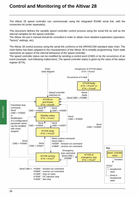
The Altivar 28 control process using the serial link conforms to the DRIVECOM standard state chart. Thechart below has been adapted to the characteristics of the Altivar 28 to simplify programming. Each staterepresents an aspect of the internal behaviour of the speed controller.The speed controller status can be modified by sending a control word (CMD) or by the occurrence of anevent (example : lock following malfunction). The speed controller status is given by the value of the statusregister (ETA).
Enter state diagram
Irrespective of ATV28 statusETA = H'xxxx'
Speed controllerswitched on
SendCMD = H'0006'
SendCMD = H'0000'
Resetfaults
Send CMD = H'0080'
Occurrence of a fault
ATV28 onand locked
ETA = H'xx40'
Standby statusETA = H'xx21'
ATV28 readyETA = H'xx23'
ATV28 faultyETA = H'xxxF' or
ETA = H'xxx8'
SendCMD = H'0007'
SendCMD = H'0000'
Freewheel stopcommand.SendCMD = H'0000'orModificationof a configurationparameter whichcan be modifiedwith motor stopped
SendCMD = H'0006' Send
CMD = H'0000'
ATV28 runningETA = H'xx27'
Emergencystop commandSend CMD =
H'000B'
ATV28 atemergency stopETA = H'xx07'
Motor control commandSend CMD = H'000F' : forward run commandH'080F' : reverse run command
Send CMD = H'000F' : forward run commandH'080F' : reverse run commandH'100F' : stop on rampH'200F' : DC injection stopH'400F' : fast stop
SendCMD = H'0007'
SendCMD = H'0006'
Speed controller status
Transition
Key
hexadecimalvalue
shows a hexadecimal value
H'xxxx'
28

EN
GLI
SH
Control and Monitoring of the Altivar 28
Stop requests which can be activated by the terminal always have priority:
Forced to localIf a logic input assigned to the forced to local function is set to 1, the commands present at the terminalsare taken into account.
In forced to local mode all write requests from the fieldbus are refused.
Warning: when forced to local mode ceases, line control is restored at the point which was activeat the moment of interrupt caused by forced to local.
Communication bus monitoring
Bit 14 (NTO) of control word CMI is used to inhibit communication monitoring. If NTO = 1, the speed controller no longer takes into account communication errors from the communicationbus controlling the speed controller.For safety reasons its use must be restricted to the debug phase.
Warning
Only those addresses and values defined in this document may be used. All other addresses andvalues should be considered as reserved and should not be written. If this precaution is notrespected it may result in malfunctions.
Type of stop Corresponding DRIVECOM state
Actions for restoring control of the Altivar 28 using the serial link
Freewheel stop "ATV28 powered up" - set the logic input assigned to the "Freewheel stop" function to 1 (active at 0)- perform the transitions required to return the speed controller to “run” status.
Fast stop "ATV28 running" - set the logic input assigned to the "Fast stop" function to 1 (active at 0)
DC injection stop "ATV28 running" - set the logic input assigned to the "DC injection braking" function to 0 (active at 1)
3-wire control stop via logic input STOP (LI1)
"ATV28 powered up" - set the logic input assigned to the STOP function to 1 (active at 0)- perform the transitions required to return the speed controller to “run” status.
29

EN
GLI
SH
Summary of "DRIVECOM" standard
Definition of bits in the control register and the status register.
The bits in the CMD control register ("controlword") have the following meaning:
Note : The grey boxes correspond to the "DRIVECOM" standard, the white boxes correspond to theadaptation of the Altivar 28 to this standard.
The commands are combinations of 5 mandatory bits.
x : state is not significant0>1 : "rising edge" (switch from 0 to 1).
bit 0 bit 1 bit 2 bit 3 bit 4 bit 5 bit 6 bit 7SWITCH ON
DISABLE VOLTAGE
QUICKSTOP
ENABLE OPERATION
optional optional optional RESETMALFUNCTION
Switch tospeed controller ready
Return to ATV 28powered upstatus
Emergencystop
run / stop
reserved reserved reserved Reset fault acknowledged
bit 8 bit 9 bit 10 bit 11 bit 12 bit 13 bit 14 bit 15reserved reserved reserved specific
to manu-facturer
specific tomanu-facturer
specificto manu-facturer
specificto manu-facturer
specificto manufacturer
reserved reserved reserved reverse the motor direction
run / stop stop byinjection
faststop
reserved
command bit 7 bit 3 bit 2 bit 1 bit 0 transition inDRIVECOM
diagram
sample values of the control
registerinitializes state Switch on disabled 1 0 0 0 0 1 00 F0HSHUT DOWN x x 1 1 0 2, 6, 8 00 76HSWITCH ON x x 1 1 1 3 00 77HDISABLE VOLTAGE x x x 0 x 7, 9, 10, 12 00 70HQUICK STOP x x 0 1 x 11 00 72HDISABLE OPERATION x 0 1 1 1 5 00 77HENABLE OPERATION x 1 1 1 1 4 00 7FHRESET MALFUNCTION 0>1 x x x x 15 00 F0H
30

EN
GLI
SH
Summary of "DRIVECOM" standard
The bits in the ETA status register ("statusword") have the following meaning:
Note : The grey boxes correspond to the "DRIVECOM" standard, the white boxes correspond to theadaptation of the Altivar 28 to this standard.
The states are coded in combinations of bits: (Note: bit 4 is not significant and is therefore not shown in thetable).
x : state is not significant
Description of other bits:bit 4 - Voltage disabled = 1 power absentbit 7 - Warning = 1 a standard or user-specific warning is presentbit 8 - Message = 1 a message (an event) is present (optional)bit 9 - Remote = 1 if the parameters can be modified via bus when not forced to localbit 10 - Setpoint reached = 1 if the reference value is reachedbit 11 - Limit value = 1 if a limit value is reached (min-max speed)
bit 0 bit 1 bit 2 bit 3 bit 4 bit 5 bit 6 bit 7Ready toswitch on
Switchedon
Operationenabled
Malfunction Voltagedisabled
Quick Stop
Switch ondisabled
Warning
not ready/ready forstartup
speed controllernot ready/
ready
stop/run
no malfunction/malfunction
poweron/off
emergencystop
in progress
speed controller
locked
Alarm
bit 8 bit 9 bit 10 bit 11 bit 12 bit 13 bit 14 bit 15Message Remote Setpoint
reachedLimit value reserved reserved specific
to manu-facturer
specific to
manufacturerreserved forced to
local/remote
referencereached
min or maxvalue
reached
reserved reserved stop viaSTOP
key
direction ofrotation
forward/reverse
command bit 6 bit 5 bit 3 bit 2 bit 1 bit 0 value of the status registerexpected value after masking
mask
NOT RDY TO SWITCH ON 0 x 0 0 0 0 - -SWITCH ON DISABLED 1 x 0 0 0 0 00 40H 00 4FHREADY TO SWITCH ON 0 1 0 0 0 1 00 21H 00 6FHSWITCH ON 0 1 0 0 1 1 00 23H 00 6FHOPERATION ENABLED 0 1 0 1 1 1 00 27H 00 6FHMALFUNCTION 0 x 1 0 0 0 00 08H 00 4FHMALFUNC. REACT. ACTIVE 0 x 1 1 1 1 - -QUICK STOP ACTIVE 0 0 0 1 1 1 00 00H 00 08H
31

EN
GLI
SH
Summary of "DRIVECOM" standard
Managing the status diagram according to the commands written by the CMD control register (controlword)
Not operablexx00H
No malfunction
Malfunction
Malfunction
Switch ONDisabledxx40H
Ready to SwitchON
xx21H
Switched ONxx23H
New com. reg.value or
Speed Reference Value
Malfunctionxxx8H
OperationEnabledxx27H
No malfunction& com. reg. = QUICK
STOP
No malfunction& com. reg. = DISABLEOPERATION
No malfunction& com. reg. = DISABLEVOLTAGE
No malfunction& com. reg. =
DISABLEVOLTAGE
No malfunction& com. reg. =
ENABLEOPERATION
11
4 5
No malfunction& com. reg. = SHUT DOWN
No malfunction& com. reg. = SHUT DOWN
No malfunction& powerpresent
& com. reg. = SWITCH ON
3
8
6
No malfunction& com. reg. = DISABLEVOLTAGE orQUICK STOP
No malfunction& com. reg. = DISABLEVOLTAGE orQUICK STOP
No malfunction& com. reg. =
SHUTDOWN
No malfunction& com. reg. = RESET
MALFUNCTION
2 7
9
1
0
15
13
Malfunction 13
Malfunction 13
Malfunction
Malfunction
13
10
Malfunction13
12
14
Quick StopActivexx07H
MalfunctionReaction active
xxxFH
32

EN
GLI
SH
Altivar 28 Variables
General configuration parameters (read and write)These parameters may only be adjusted with the motor stopped, except SdS and SFr, which can beadjusted with the motor running.
Word Code Unit Description Possible values or rangeW4 CrL 0.1 mA Minimum reference of input AI2 0 to 200
W5 CrH 0.1 mA Maximum reference of input AI2 40 to 200
W6 tCC 2-wire / 3-wire control via terminalsModification of this parameterwill reassign the I/O
0 = 2 C : 2-wire control1 = 3 C : 3-wire control2 = OPt : local control option present, in this case writing is impossible.
W10 Add Address of the speed controller via the standard serial link
1 to 31
W16 bdr Serial link transmission speed. This parameter is not actually modified until the speed controller has been switched off and on again.
7 = 9600 bps8 = 19200 bps
W40 bFr Motor configuration 50 or 60 Hz 0 = 50 Hz1 = 60 Hz
W41 SdS Scale factor of SPd parameter(speed display)Can be adjusted whilst operating
1 to 200
W42 AOt Configuration of analogue output as 0 - 20 mA or 4 - 20 mA
0 = 0 - 20 mA1 = 4 - 20 mA
W51 SFr 0.1 kHz Switching frequencyCan be adjusted whilst operating
20 to 150 (2 to 15 kHz)
W52 tFr 0.1 Hz Maximum frequency 400 to 4000
W53 FrS 0.1 Hz Nominal motor frequency 400 to 4000
W55 UnS 1 V Nominal motor voltage ATV-28•••M2 : 200 to 240ATV-28•••N4 : 380 to 500
33
EN
GLI
SH
Altivar 28 Variables
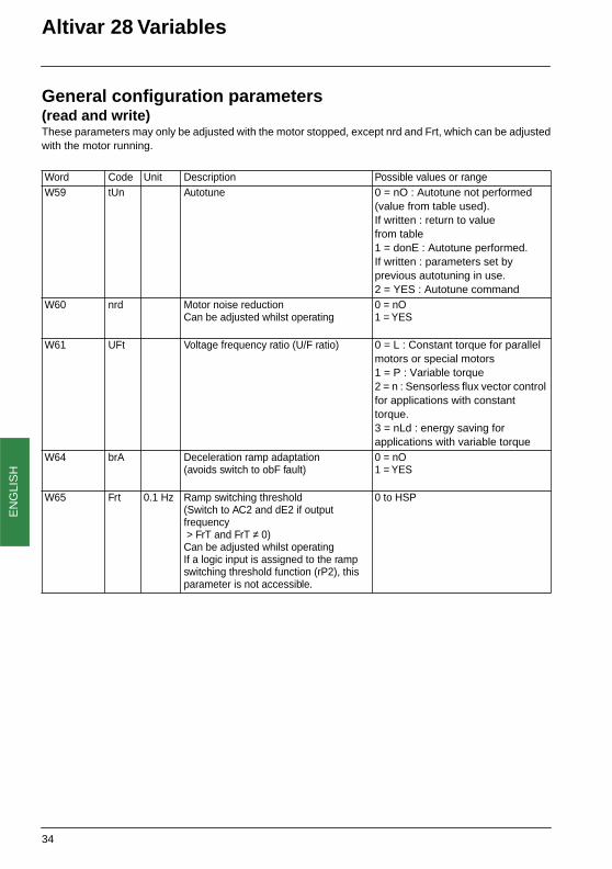
General configuration parameters (read and write)These parameters may only be adjusted with the motor stopped, except nrd and Frt, which can be adjustedwith the motor running.
Word Code Unit Description Possible values or rangeW59 tUn Autotune 0 = nO : Autotune not performed
(value from table used). If written : return to valuefrom table1 = donE : Autotune performed.If written : parameters set by previous autotuning in use. 2 = YES : Autotune command
W60 nrd Motor noise reductionCan be adjusted whilst operating
0 = nO1 = YES
W61 UFt Voltage frequency ratio (U/F ratio) 0 = L : Constant torque for parallel motors or special motors1 = P : Variable torque2 = n : Sensorless flux vector control for applications with constant torque.3 = nLd : energy saving for applications with variable torque
W64 brA Deceleration ramp adaptation (avoids switch to obF fault)
0 = nO1 = YES
W65 Frt 0.1 Hz Ramp switching threshold (Switch to AC2 and dE2 if output frequency > FrT and FrT ≠ 0)Can be adjusted whilst operatingIf a logic input is assigned to the ramp switching threshold function (rP2), this parameter is not accessible.
0 to HSP
34

EN
GLI
SH
Altivar 28 Variables
I/O configuration parameters (read and write)These parameters may only be adjusted with the motor stopped.
Word Code Description Possible values or rangeW100 LI1 Assignment of logic input "LI1"
Write protected0 = Not assigned (local control option present, tCC = OPt)1 = Stop (if tCC = 3C)2 = Forward operation (if tCC = 2C)
W101 LI2 Assignment of logic input "LI2"Write protected if tCC = 3C
0 = nO : Not assigned2 = For : Forward operation. (If tCC = 3C)3 = rrS : Reverse operation4 = rP2 : Ramp switching5 = JOG : Jog operation8 = PS2 : 2 preset speeds9 = PS4 : 4 preset speeds10 = PS8 : 8 preset speeds11 = rFC : Reference switching12 = nSt : Freewheel stop13 = dCI : Injection stop14 = FSt : Fast stop17 = FLO : Forced local18 = rSt : Clear faults
W102 LI3 Assignment of logic input "LI3" 0 = nO : Not assigned3 = rrS : Reverse operation4 = rP2 : Ramp switching5 = JOG : Jog operation8 = PS2 : 2 preset speeds9 = PS4 : 4 preset speeds10 = PS8 : 8 preset speeds11 = rFC : Reference switching12 = nSt : Freewheel stop13 = dCI : Injection stop14 = FSt : Fast stop17 = FLO : Forced local18 = rSt : Clear faults
W103 LI4 Assignment of logic input "LI4" 0 = nO : Not assigned3 = rrS : Reverse operation4 = rP2 : Ramp switching5 = JOG : Jog operation8 = PS2 : 2 preset speeds9 = PS4 : 4 preset speeds10 = PS8 : 8 preset speeds11 = rFC : Reference switching12 = nSt : Freewheel stop13 = dCI : Injection stop14 = FSt : Fast stop17 = FLO : Forced local18 = rSt : Clear faults
35
EN
GLI
SH
Altivar 28 Variables
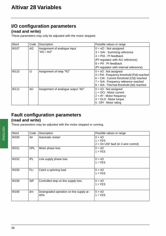
I/O configuration parameters (read and write)These parameters may only be adjusted with the motor stopped.
Fault configuration parameters(read and write)These parameters may be adjusted with the motor stopped or running.
Word Code Description Possible values or rangeW107 AI2 Assignment of analogue input
"AIC / AI2"0 = nO : Not assigned3 = SAI : Summing reference4 = PIA : PI feedback(PI regulator with AI1 reference)8 = PII : PI feedback(PI regulator with internal reference)
W110 r2 Assignment of relay "R2" 0 = nO : Not assigned4 = FtA : Frequency threshold (Ftd) reached6 = CtA : Current threshold (Ctd) reached7 = SrA : Frequency reference reached8 = tSA : Thermal threshold (ttd) reached
W112 AO Assignment of analogue output "AO" 0 = nO : Not assigned1 = OCr : Motor current2 = rFr : Motor frequency4 = OLO : Motor torque5 : OPr : Motor rating
Word Code Description Possible values or rangeW150 Atr Automatic restart 0 = nO
1 = YES2 = On USF fault (in 2-wire control)
W151 OPL Motor phase loss 0 = nO1 = YES
W152 IPL Line supply phase loss 0 = nO1 = YES
W155 FLr Catch a spinning load 0 = nO1 = YES
W156 StP Controlled stop on line supply loss 0 = nO1 = YES
W190 drn Downgraded operation on line supply at - 40%
0 = nO1 = YES
36
EN
GLI
SH
Altivar 28 Variables
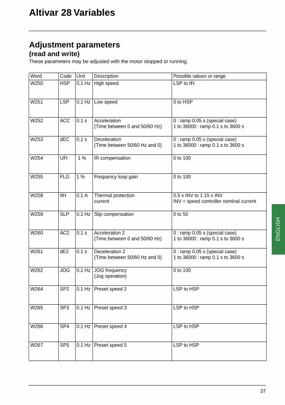
Adjustment parameters(read and write)These parameters may be adjusted with the motor stopped or running.
Word Code Unit Description Possible values or rangeW250 HSP 0.1 Hz High speed LSP to tFr
W251 LSP 0.1 Hz Low speed 0 to HSP
W252 ACC 0.1 s Acceleration(Time between 0 and 50/60 Hz)
0 : ramp 0.05 s (special case)1 to 36000 : ramp 0.1 s to 3600 s
W253 dEC 0.1 s Deceleration (Time between 50/60 Hz and 0)
0 : ramp 0.05 s (special case)1 to 36000 : ramp 0.1 s to 3600 s
W254 UFr 1 % IR compensation 0 to 100
W255 FLG 1 % Frequency loop gain 0 to 100
W258 ItH 0.1 A
Thermal protection current
0.5 x INV to 1.15 x INVINV = speed controller nominal current
W259 SLP 0.1 Hz Slip compensation 0 to 50
W260 AC2 0.1 s Acceleration 2(Time between 0 and 50/60 Hz)
0 : ramp 0.05 s (special case)1 to 36000 : ramp 0.1 s to 3600 s
W261 dE2 0.1 s Deceleration 2(Time between 50/60 Hz and 0)
0 : ramp 0.05 s (special case)1 to 36000 : ramp 0.1 s to 3600 s
W262 JOG 0.1 Hz JOG frequency(Jog operation)
0 to 100
W264 SP2 0.1 Hz Preset speed 2 LSP to HSP
W265 SP3 0.1 Hz Preset speed 3 LSP to HSP
W266 SP4 0.1 Hz Preset speed 4 LSP to HSP
W267 SP5 0.1 Hz Preset speed 5 LSP to HSP
37

EN
GLI
SH
Altivar 28 Variables
Adjustment parameters(read and write)These parameters may be adjusted with the motor stopped or running.
Word Code Unit Description Possible values or rangeW268 SP6 0.1 Hz Preset speed 6 LSP to HSP
W269 SP7 0.1 Hz Preset speed 7 LSP to HSP
W270 IdC 0.1 A Injection current 0.1 ItH to INV(INV = speed controller nominal current)
W271 tdC 0.1 s Injection time(In the case of automatic injection on stopping)
0 to 254 = time 0.0 s to 25.4 s255 = CONT : continuous injection
W272
tLS 0.1 s Maximum time at low speed (LSP)
0 = NO : no limit 1 to 255 = time from 0.1 s to 25.5 s
W279 rPG 0.01 PI proportional gain 1 to 10000 (gain from 0.01 to 100)
W280 rIG 0.01/s PI integral gain 1 to 10000 (gain from 0.01/s to 100/s)
W281 FbS 0,1 PI feedback scale factor 1 to 1000 (factor 0.1 to 100)
W282 Ctd 0.1 A Current threshold reached 0.1 x INV to 1.5 x INVINV. = speed controller nominal current
W283 ttd 1 % Thermal threshold reached 1 to 118
W284 Ftd 0.1 Hz Frequency threshold reached 0 to HSP
W286 JPF 0.1 Hz Skip frequency on a frequencyrange of ± 1 Hz around the adjusted value
0 to HSP
W287 PIC Reversal of direction of correctionof PI regulator
0 = nO1 = YES
W340 rOt Control of operating direction with "local control" option.This parameter is only accessible in read mode.
0 = FOr : forward1 = rrS : reverse
38
EN
GLI
SH
Altivar 28 Variables
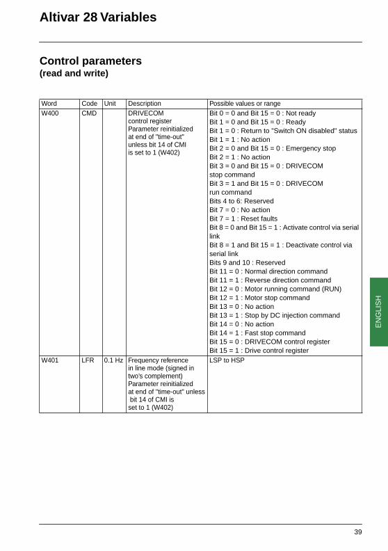
Control parameters(read and write)
Word Code Unit Description Possible values or rangeW400 CMD DRIVECOM
control register Parameter reinitialized at end of "time-out" unless bit 14 of CMI is set to 1 (W402)
Bit 0 = 0 and Bit 15 = 0 : Not readyBit 1 = 0 and Bit 15 = 0 : Ready Bit 1 = 0 : Return to "Switch ON disabled" statusBit 1 = 1 : No actionBit 2 = 0 and Bit 15 = 0 : Emergency stopBit 2 = 1 : No actionBit 3 = 0 and Bit 15 = 0 : DRIVECOM stop command Bit 3 = 1 and Bit 15 = 0 : DRIVECOM run command Bits 4 to 6: ReservedBit 7 = 0 : No actionBit 7 = 1 : Reset faultsBit 8 = 0 and Bit 15 = 1 : Activate control via serial linkBit 8 = 1 and Bit 15 = 1 : Deactivate control via serial linkBits 9 and 10 : ReservedBit 11 = 0 : Normal direction commandBit 11 = 1 : Reverse direction commandBit 12 = 0 : Motor running command (RUN)Bit 12 = 1 : Motor stop commandBit 13 = 0 : No actionBit 13 = 1 : Stop by DC injection commandBit 14 = 0 : No actionBit 14 = 1 : Fast stop commandBit 15 = 0 : DRIVECOM control register Bit 15 = 1 : Drive control register
W401 LFR 0.1 Hz Frequency reference in line mode (signed in two’s complement) Parameter reinitialized at end of "time-out" unless bit 14 of CMI isset to 1 (W402)
LSP to HSP
39

EN
GLI
SH
Altivar 28 Variables
Control parameters(read and write)
(1) Each action of bits 0, 1, and 2 of W402 is only accepted if the motor is stopped and the speed controllerpowered up without a USF fault. When accepted, it interrupts communication while it executes, or for 2seconds max. The PLC "time out" must therefore be set to a higher value in order to avoid tripping.During this time the speed controller display indicates :• IIIInnnnIIIItttt to return to factory settings and to return to EEPROM parameters (bits 0 and 2)• NNNNEEEENNNNOOOO to memorize write operations in EEPROM (bit 1). If several of these bits are activated simultaneously, the following priorities are respected :• bit 0 has priority over bits 1 and 2• bit 1 has priority over bit 2
Word Code Unit Description Possible values or rangeW402 CMI Internal control
register (application program)Parameter reinitialized at end of "time-out" unless bit 14 of CMI is set to 1
Bit 0 = 0 : No actionBit 0 = 1 : (1) Return to factory settings.This bit automatically resets to 0 after accepting the request.Bit 1 = 0 : No actionBit 1 = 1 : (1) Memorize in EEPROM configuration and adjustment words which have been the object of a write request. This bit must be reset to 0 by the PLC after accepting the request.Bit 2 = 0 : No actionBit 2 = 1 : (1) Return to parameters memorized in EEPROM (cancel write operations). This bit must be reset to 0 by the PLC after accepting the request.Bit 3 : ReservedBit 4 = 0 : No actionBit 4 = 1 : Ramp switching commandBits 5 to 12 : ReservedBit 13 = 0 : Speed controller not locked on stopBit 13 = 1 : Speed controller locked on stopBit 14 (NTO) = 0 : Control with monitoring of communication.
Bit 14 (NTO) = 1 : Control without monitoring of communication. For safety reasons this should be reserved for the debug phase.
Bit 15 : ReservedW440 rPI 0.1% PI regulator
internal setpoint (if AIC / AI2 = PII)
0 to 1000
40

EN
GLI
SH
Altivar 28 Variables
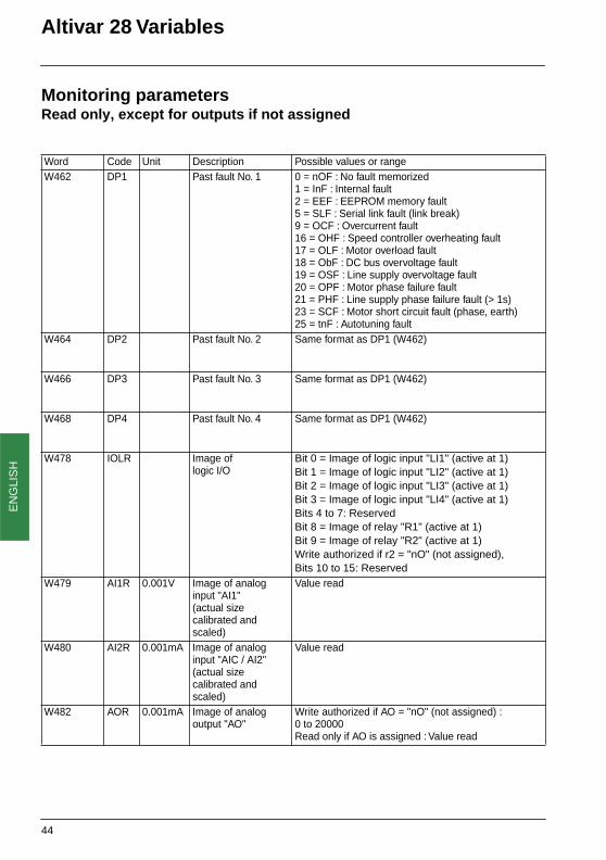
Monitoring parametersRead only, except for outputs if not assigned
Word Code Unit Description Possible values or rangeW450 FrH 0.1Hz Frequency reference
(absolute value)Value read
W451 rFr 0.1Hz Output frequencyapplied to motor(absolute value)
Value read
W452 SPd 1 Motor speed estimated by speed controller (absolute value)
Value read
W453 LCr 0.1A Current in motor Value read
W454 ULn 0.1V Line voltage(from bus)
Value read
W455 tHr 1% Motor thermal state(100 % = Nominal thermal state, 118 % = OLF threshold)
Value read
W456 tHd 1% Speed controller thermal state(100 % = Nominal thermal state, 118 % = OHF threshold)
Value read
W457 LFt Last fault 0 = nOF : No fault memorized1 = InF : Internal fault2 = EEF : EEPROM memory fault5 = SLF : Serial link fault
(link break)9 = OCF : Overcurrent fault16 = OHF : Speed controller overheating
fault (on heatsink)
17 = OLF : Motor overload fault 18 = ObF : DC bus overvoltage fault19 = OSF : Line supply overvoltage fault20 = OPF : Motor phase failure fault21 = PHF : Line supply phase failure fault23 = SCF : Motor short circuit fault
(phase, earth)25 = tnF : Autotuning fault
41

EN
GLI
SH
Altivar 28 Variables
Monitoring parametersRead only, except for outputs if not assigned
Word Code Description Possible values or rangeW458 ETA DRIVECOM
speed controllerstatus register
Bit 0 = 0 : Power not readyBit 0 = 1 : Power ready for startupBit 1 = 0 : Speed controller not readyBit 1 = 1 : Speed controller ready (rdY)Bit 2 = 0 : DRIVECOM stopBit 2 = 1 : DRIVECOM runBit 3 = 0 : Fault absentBit 3 = 1 : Fault present (FAI)Bit 4 = 0 : Power presentBit 4 = 1 : Power absentBit 5 = 0 : Emergency stop in progressBit 5 = 1 : Emergency stop absentBit 6 = 0 : Status ≠ SWITCH ON DISABLED (freewheel stop)Bit 6 = 1 : Status ≠ SWITCH ON DISABLED (freewheel stop)Bit 7 = 0 : Alarm absentBit 7 = 1 : Alarm presentBit 8 = ReservedBit 9 = 0 : Forced local in progress (FLO)Bit 9 = 1 : Forced local absentBit 10 = 0 : Reference not reached (transient state)Bit 10 = 1 : Reference reached (steady state)Bit 11 = 0 : LFRD reference normalBit 11 = 1 : LFRD reference exceeded (> HSP or < LSP)Bits 12 and 13 : ReservedBit 14 = 0 : No stop from STOP key
(remote keypad)Bit 14 = 1 : Stop from STOP key
(remote keypad)Bit 15 = 0 : Forward direction of rotation (output frequency)Bit 15 = 1 : Reverse direction of rotation (output frequency)
42

EN
GLI
SH
Altivar 28 Variables
Monitoring parametersRead only, except for outputs if not assigned
Word Code Description Possible values or rangeW459 ETI Speed controller
internal status register no. 1
Bits 0 to 3: ReservedBit 4 = 0 : Motor stoppedBit 4 = 1 : Motor runningBit 5 = 0 : No DC injection Bit 5 = 1 : DC injectionBit 6 = 0 : Speed controller in steady stateBit 6 = 1 : Speed controller in transient stateBit 7 = 0 : No thermal overload alarmBit 7 = 1 : Thermal overload alarmBit 8 = 0 : No alarm if excessive brakingBit 8 = 1 : Alarm if excessive brakingBits 9 and 10 = ReservedBit 11 = 0 : No current limit alarm Bit 11 = 1 : Current limit alarm Bit 12 = ReservedBit 14 = 0, Bit 13 = 0 : Drive controlled via terminalsBit 14 = 0, Bit 13 = 1 : Drive controlled via remote keypadBit 14 = 1, Bit 13 = 0 : Drive controlled via serial linkBit 15 = 0 : Forward direction of rotation requested (reference)Bit 15 = 1 : Reverse direction of rotation requested (reference)
W460 ETI2 Speed controllerinternal status register no. 2
Bits 0 to 3: ReservedBit 4 = 0 : Speed reference not reachedBit 4 = 1 : Speed reference reachedBit 5 = 0 : Frequency threshold (Ftd) not reachedBit 5 = 1 : Frequency threshold (Ftd) reachedBit 6 = 0 : Current threshold (Ctd) not reachedBit 6 = 1 : Current threshold (Ctd) reachedBits 7 to 15: Reserved
W461 ETI3 Speed controllerinternal status register no. 3
Reserved
43
EN
GLI
SH
Altivar 28 Variables
Monitoring parametersRead only, except for outputs if not assigned
Word Code Unit Description Possible values or rangeW462 DP1 Past fault No. 1 0 = nOF : No fault memorized
1 = InF : Internal fault2 = EEF : EEPROM memory fault5 = SLF : Serial link fault (link break)9 = OCF : Overcurrent fault16 = OHF : Speed controller overheating fault 17 = OLF : Motor overload fault 18 = ObF : DC bus overvoltage fault19 = OSF : Line supply overvoltage fault20 = OPF : Motor phase failure fault21 = PHF : Line supply phase failure fault (> 1s)23 = SCF : Motor short circuit fault (phase, earth)25 = tnF : Autotuning fault
W464 DP2 Past fault No. 2 Same format as DP1 (W462)
W466 DP3 Past fault No. 3 Same format as DP1 (W462)
W468 DP4 Past fault No. 4 Same format as DP1 (W462)
W478 IOLR Image of logic I/O
Bit 0 = Image of logic input "LI1" (active at 1)Bit 1 = Image of logic input "LI2" (active at 1)Bit 2 = Image of logic input "LI3" (active at 1)Bit 3 = Image of logic input "LI4" (active at 1)Bits 4 to 7: ReservedBit 8 = Image of relay "R1" (active at 1)Bit 9 = Image of relay "R2" (active at 1)Write authorized if r2 = "nO" (not assigned),Bits 10 to 15: Reserved
W479 AI1R 0.001V Image of analog input "AI1" (actual size calibrated and scaled)
Value read
W480 AI2R 0.001mA Image of analog input "AIC / AI2" (actual size calibrated and scaled)
Value read
W482 AOR 0.001mA Image of analog output "AO"
Write authorized if AO = "nO" (not assigned) : 0 to 20000Read only if AO is assigned : Value read
44
EN
GLI
SH
Altivar 28 Variables
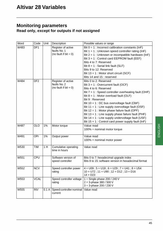
Monitoring parametersRead only, except for outputs if not assigned
Word Code Unit Description Possible values or rangeW483 DF1 Register of active
faults No. 1 (no fault if bit = 0)
Bit 0 = 1 : Incorrect calibration constants (InF) Bit 1 = 1 : Unknown speed controller rating (InF)Bit 2 = 1 : Unknown or incompatible hardware (InF)Bit 3 = 1 : Control card EEPROM fault (EEF)Bits 4 to 7: ReservedBit 8 = 1 : Serial link fault (SLF)Bits 9 to 12: ReservedBit 13 = 1 : Motor short circuit (SCF)Bits 14 and 15 : reserved
W484 DF2 Register of active faults No. 2 (no fault if bit = 0)
Bits 0 to 2: ReservedBit 3 = 1 : Overcurrent fault (OCF)Bits 4 to 6: ReservedBit 7 = 1 : Speed controller overheating fault (OHF)Bit 8 = 1 : Motor overload fault (OLF)Bit 9 : ReservedBit 10 = 1 : DC bus overvoltage fault (ObF)Bit 11 = 1 : Line supply overvoltage fault (OSF)Bit 12 = 1 : Motor phase failure fault (OPF)Bit 13 = 1 : Line supply phase failure fault (PHF)Bit 14 = 1 : Line supply undervoltage fault (USF)Bit 15 = 1 : Control card power supply fault (InF)
W487 OLO 1% Motor torque Value read100% = nominal motor torque
W491 OPr 1% Output power Value read100% = nominal motor power
W530 TIM 1 H Cumulative operating time in hours
Value read
W551 CPU Software version of speed controller
Bits 0 to 7: hexadecimal upgrade indexBits 8 to 15: software version in hexadecimal format
W552 NCV Speed controller power rating
4 = U09 ; 5 = U18 ; 6 = U29 ; 7 = U41 ; 8 = U5410 = U72 ; 11 = U90 ; 12 = D12 ; 13 = D1614 = D23
W553 VCAL Speed controller voltage rating
1 = Single phase 200 / 240 V2 = 3-phase 380 / 500 V3 = 3-phase 200 / 230 V
W555 INV 0.1 A Speed controller nominal current
Value read
45

EN
GLI
SH
Altivar 28 Variables
Special "DRIVECOM" parameters(read and write)Use of parameters W603 to W615 necessitates a special configuration of parameter SdS (W41) in driveparameter menu drC- :SdS = 60/p where p = number of pairs of poles in motor.Example : motor 1450 Rpm (revolutions per minute) at 50Hz : 4-pole motor, so SdS = 30.This parameter enables the speed controller to establish the relationship between the frequency in Hz andthe speed in Rpm.
Word Code Unit Description Possible values or rangeW600 ERRD Error code (603FH)
Write protected0 = nOF : No fault1000H = OLF : Motor overload fault 2310H = OCF : Overcurrent fault3110H = OSF : Line supply overvoltage fault3120H = USF : Line supply undervoltage fault3130H = PHF : Line supply phase failure fault3310H = ObF : DC bus overvoltage fault or3310H = OPF : Motor phase failure fault4210H = OHF : Speed controller overheating fault 5520H = EEF : EEPROM memory fault6100H = InF : Internal fault7510H = SLF : Serial link fault
W601 CMDD Control wordSame as parameter "CMD" (W400)
W602 ETAD Status wordSame as parameter "ETA" (W458)Write protected
W603 LFRD 1 Rpm Speed reference(reference not peak limited)
- 32768 to 32767
W604 FRHD 1 Rpm Ramp output signedWrite protected
- 32768 to 32767
W605 RFRD 1 Rpm Motor speedWrite protected
0 to 65535
W606 SMIL 1 Rpm Low speed, equivalent to LSP (W251), but in revolutions/minute
0 to (HSP x SdS)
W607 SMIH Reserved 0
W608 SMAL 1 Rpm High speed, equivalent to HSP (W250), but in revolutions/minute
(LSP x SdS) to (tFr x SdS)
W609 SMAH Reserved 0
46
EN
GLI
SH
Altivar 28 Variables
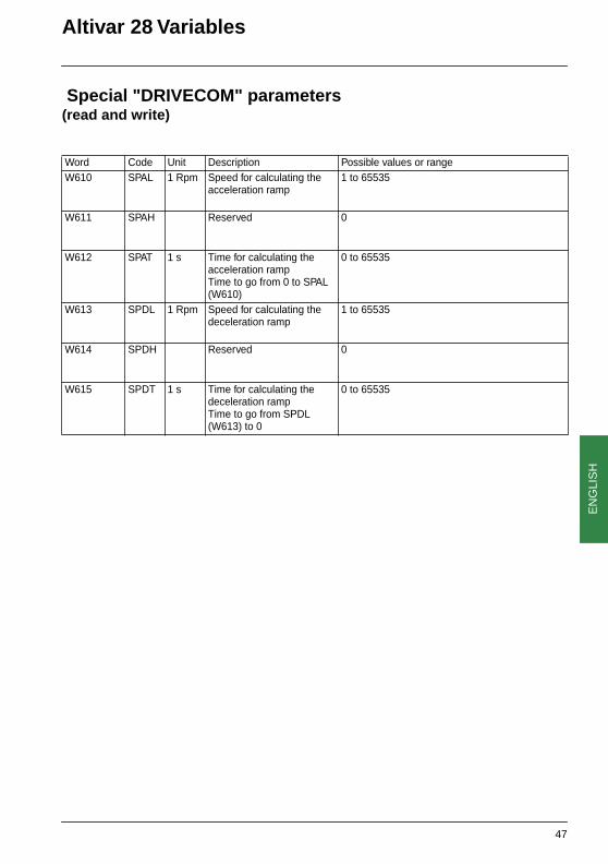
Special "DRIVECOM" parameters(read and write)
Word Code Unit Description Possible values or rangeW610 SPAL 1 Rpm Speed for calculating the
acceleration ramp1 to 65535
W611 SPAH Reserved 0
W612 SPAT 1 s Time for calculating the acceleration rampTime to go from 0 to SPAL (W610)
0 to 65535
W613 SPDL 1 Rpm Speed for calculating the deceleration ramp
1 to 65535
W614 SPDH Reserved 0
W615 SPDT 1 s Time for calculating the deceleration rampTime to go from SPDL (W613) to 0
0 to 65535
47

EN
GLI
SH
Index of addresses
Address Description PageW4toW55
General configuration parameters page 33
W59toW65
General configuration parameters page 34
W100toW103
I/O configuration parameters page 35
W107toW112
I/O configuration parameters page 36
W150toW190
Fault configuration parameters page 36
W250toW267
Adjustment parameters page 37
W268toW340
Adjustment parameters page 38
W400toW401
Control parameters page 39
W402toW440
Control parameters page 40
W450toW457
Monitoring parameters page 41
W458 Monitoring parameters page 42
W459toW461
Monitoring parameters page 43
W462toW482
Monitoring parameters page 44
W483toW555
Monitoring parameters page 45
W600toW609
Special "DRIVECOM" parameters page 46
W610toW615
Special "DRIVECOM" parameters page 47
48

VVDED399064
27454
W9 1494186 01 11 A01
1999-11


![Altivar 18 Telemecanique - Elmatik speed drives Altivar 18 User Guide...Altivar 18 Telemecanique Jmdh\h^kl\h Ij_h[jZah\Zl_eb qZklhlu ih wdkiemZlZpbb ^ey Zkbgojhgguo ^\b]Zl_e_c. 6 1](https://static.fdocuments.us/doc/165x107/5ec0a3b09d489557bf438e23/altivar-18-telemecanique-speed-drives-altivar-18-user-guide-altivar-18-telemecanique.jpg)


