Altimeter INDU 80 | Manual · and Inkscape applications. Photos and scanned material was processed...
11
Altimeter INDU 80 — Manual Kanardia d.o.o. March 2016 Kanardia d.o.o. Manual Revision 1.3
Transcript of Altimeter INDU 80 | Manual · and Inkscape applications. Photos and scanned material was processed...
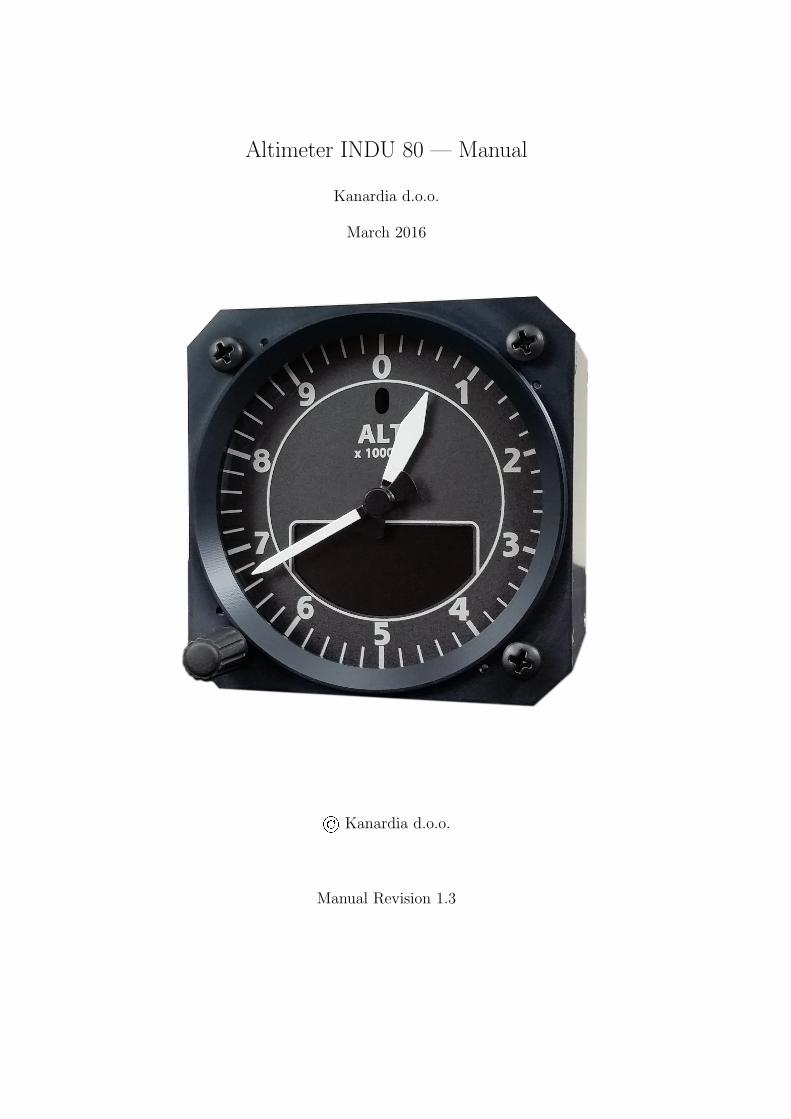
Altimeter INDU 80 — Manual
Kanardia d.o.o.
March 2016
© Kanardia d.o.o.
Manual Revision 1.3
Contact Information
Publisher and producer:Kanardia d.o.o.Lopata 24aSI-3000Slovenia
Tel: +386 40 360 512Email: [email protected]
A lot of useful and recent information can be also found on the Internet. See http://www.
kanardia.eu for more details.
Copyright
This document is published under the Creative Commons, Attribution-ShareAlike 3.0 Un-ported licence. Full license is available on http://creativecommons.org/licenses/by-sa/
3.0/legalcode web page and a bit more human readable summary is given on http:
//creativecommons.org/licenses/by-sa/3.0/. In short, the license gives you right tocopy, reproduce and modify this document if:
� you cite Kanardia d.o.o. as the author of the original work,
� you distribute the resulting work only under the same or similar license to this one.
Credits
This document was written using TeTeX (LATEX) based document creation system using Kilerunning on Linux operating system. Most of the figures were drawn using Open Office Drawand Inkscape applications. Photos and scanned material was processed using Gimp. Sam2pwas used to convert pictures into eps format. All document sources are freely available onrequest under the licence mentioned above and can be obtained by email. Please send requeststo [email protected].
Revision History
The following table shows the revision history of this document.
Rev. Date Description
1.0 Feb 2015 Initial release
1.1 Oct 2015 Altitude model is extended up to 20000 m.
1.2 Dec 2015 Procedures for QNH toggle and IAS auto zero.
1.3 Mar 2016 Procedure for Illumination wheel activation.
Altimeter — Manual CONTENTS
Contents
1 Introduction 3
1.1 General Description . . . . . . . . . . . . . . . . . . . . . . . . . . . . . . . . 3
1.2 Technical Specification . . . . . . . . . . . . . . . . . . . . . . . . . . . . . . . 3
1.3 Options . . . . . . . . . . . . . . . . . . . . . . . . . . . . . . . . . . . . . . . 3
2 Installation & Maintenance 4
2.1 Mounting Dimensions . . . . . . . . . . . . . . . . . . . . . . . . . . . . . . . 4
2.2 Connections . . . . . . . . . . . . . . . . . . . . . . . . . . . . . . . . . . . . . 4
2.2.1 Static Connection . . . . . . . . . . . . . . . . . . . . . . . . . . . . . 4
2.2.2 CAN Bus Connection . . . . . . . . . . . . . . . . . . . . . . . . . . . 5
2.2.3 Illumination . . . . . . . . . . . . . . . . . . . . . . . . . . . . . . . . . 6
2.3 Power Connection . . . . . . . . . . . . . . . . . . . . . . . . . . . . . . . . . 6
2.4 Maintenance . . . . . . . . . . . . . . . . . . . . . . . . . . . . . . . . . . . . 6
2.5 Repair . . . . . . . . . . . . . . . . . . . . . . . . . . . . . . . . . . . . . . . . 6
2.6 Static Sensor Offset . . . . . . . . . . . . . . . . . . . . . . . . . . . . . . . . 6
2.7 Toggle QNH hPa – inHg . . . . . . . . . . . . . . . . . . . . . . . . . . . . . . 7
2.8 Airspeed Indicator Auto Zero . . . . . . . . . . . . . . . . . . . . . . . . . . . 7
2.9 Toggle Illumination Knob . . . . . . . . . . . . . . . . . . . . . . . . . . . . . 7
3 Calibration And Pressure Altitude 8
3.1 Calibration . . . . . . . . . . . . . . . . . . . . . . . . . . . . . . . . . . . . . 8
3.2 Pressure Altitude . . . . . . . . . . . . . . . . . . . . . . . . . . . . . . . . . . 8
4 Limited Conditions 9
4.1 Warranty . . . . . . . . . . . . . . . . . . . . . . . . . . . . . . . . . . . . . . 9
4.2 TSO Information — Limited Operation . . . . . . . . . . . . . . . . . . . . . 10
2 © Kanardia 2015-2016
Altimeter — Manual 1. Introduction
1 Introduction
First of all, we would like to thank you for purchasing our device. Indu altimeter is anelectronic device, which mimics classical altimeter construction and combines it with thestate of the art electronics. This results in the best of both worlds; a perfect and intuitiveanalogue reading combined with high precision of modern electronics.
This manual describes the technical description of the unit, installation and operation.
1.1 General Description
The altimeter is an electromechanical device. It consist of high precision electronic barometricsensor, which provides static pressure information in digital form. The electronics readsthe sensor and drives two coaxial stepper motors turning one needle each. The pressureinformation is also shown on a colour LCD display. A rotating knob is used to adjust thebarometric offset (aka QNH value). When connected to a CAN bus the altimeter outputs thepressure information. An optional dim knob can be connected to the device and it is used toadjust the brightness of the screen.
Display is divided linearly in 360◦scale. The large pointer is working in 1000 m (feet) perrevolution with the 20 m markings (20 feet). The small pointer is working in 10000 m (feet)per revolution with 200 m markings (200 feet).
1.2 Technical Specification
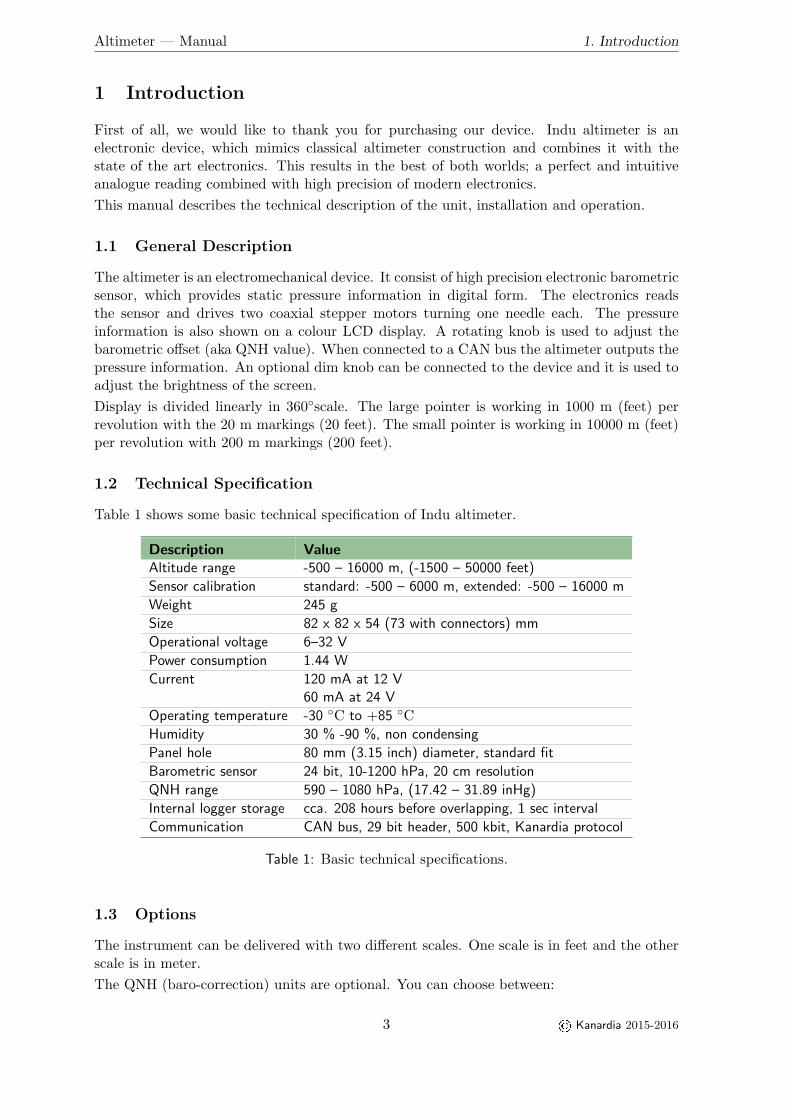
Table 1 shows some basic technical specification of Indu altimeter.
Description ValueAltitude range -500 – 16000 m, (-1500 – 50000 feet)
Sensor calibration standard: -500 – 6000 m, extended: -500 – 16000 m
Weight 245 g
Size 82 x 82 x 54 (73 with connectors) mm
Operational voltage 6–32 V
Power consumption 1.44 W
Current 120 mA at 12 V60 mA at 24 V
Operating temperature -30 ◦C to +85 ◦C
Humidity 30 % -90 %, non condensing
Panel hole 80 mm (3.15 inch) diameter, standard fit
Barometric sensor 24 bit, 10-1200 hPa, 20 cm resolution
QNH range 590 – 1080 hPa, (17.42 – 31.89 inHg)
Internal logger storage cca. 208 hours before overlapping, 1 sec interval
Communication CAN bus, 29 bit header, 500 kbit, Kanardia protocol
Table 1: Basic technical specifications.
1.3 Options
The instrument can be delivered with two different scales. One scale is in feet and the otherscale is in meter.
The QNH (baro-correction) units are optional. You can choose between:
3 © Kanardia 2015-2016
Altimeter — Manual 2. Installation & Maintenance
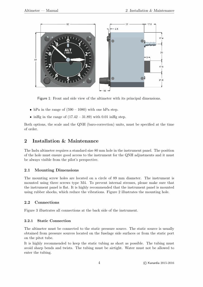
Figure 1: Front and side view of the altimeter with its principal dimensions.
� hPa in the range of (590 – 1080) with one hPa step.
� inHg in the range of (17.42 – 31.89) with 0.01 inHg step.
Both options, the scale and the QNH (baro-correction) units, must be specified at the timeof order.
2 Installation & Maintenance
The Indu altimeter requires a standard size 80 mm hole in the instrument panel. The positionof the hole must ensure good access to the instrument for the QNH adjustments and it mustbe always visible from the pilot’s perspective.
2.1 Mounting Dimensions
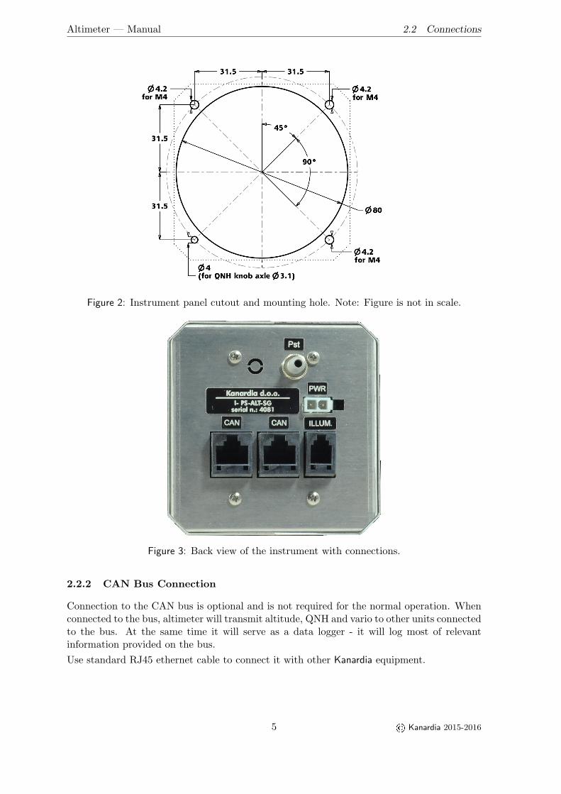
The mounting screw holes are located on a circle of 89 mm diameter. The instrument ismounted using three screws type M4. To prevent internal stresses, please make sure thatthe instrument panel is flat. It is highly recommended that the instrument panel is mountedusing rubber shocks, which reduce the vibrations. Figure 2 illustrates the mounting hole.
2.2 Connections
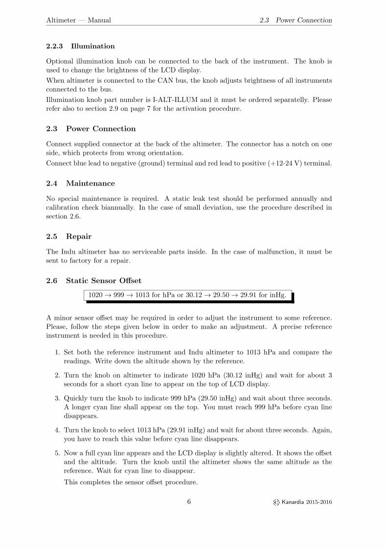
Figure 3 illustrates all connections at the back side of the instrument.
2.2.1 Static Connection
The altimeter must be connected to the static pressure source. The static source is usuallyobtained from pressure sources located on the fuselage side surfaces or from the static porton the pitot tube.
It is highly recommended to keep the static tubing as short as possible. The tubing mustavoid sharp bends and twists. The tubing must be airtight. Water must not be allowed toenter the tubing.
4 © Kanardia 2015-2016
Altimeter — Manual 2.2 Connections
Figure 2: Instrument panel cutout and mounting hole. Note: Figure is not in scale.
Figure 3: Back view of the instrument with connections.
2.2.2 CAN Bus Connection
Connection to the CAN bus is optional and is not required for the normal operation. Whenconnected to the bus, altimeter will transmit altitude, QNH and vario to other units connectedto the bus. At the same time it will serve as a data logger - it will log most of relevantinformation provided on the bus.
Use standard RJ45 ethernet cable to connect it with other Kanardia equipment.
5 © Kanardia 2015-2016
Altimeter — Manual 2.3 Power Connection
2.2.3 Illumination
Optional illumination knob can be connected to the back of the instrument. The knob isused to change the brightness of the LCD display.
When altimeter is connected to the CAN bus, the knob adjusts brightness of all instrumentsconnected to the bus.
Illumination knob part number is I-ALT-ILLUM and it must be ordered separatelly. Pleaserefer also to section 2.9 on page 7 for the activation procedure.
2.3 Power Connection
Connect supplied connector at the back of the altimeter. The connector has a notch on oneside, which protects from wrong orientation.
Connect blue lead to negative (ground) terminal and red lead to positive (+12-24 V) terminal.
2.4 Maintenance
No special maintenance is required. A static leak test should be performed annually andcalibration check biannually. In the case of small deviation, use the procedure described insection 2.6.
2.5 Repair
The Indu altimeter has no serviceable parts inside. In the case of malfunction, it must besent to factory for a repair.
2.6 Static Sensor Offset
1020 → 999 → 1013 for hPa or 30.12 → 29.50 → 29.91 for inHg.
A minor sensor offset may be required in order to adjust the instrument to some reference.Please, follow the steps given below in order to make an adjustment. A precise referenceinstrument is needed in this procedure.
1. Set both the reference instrument and Indu altimeter to 1013 hPa and compare thereadings. Write down the altitude shown by the reference.
2. Turn the knob on altimeter to indicate 1020 hPa (30.12 inHg) and wait for about 3seconds for a short cyan line to appear on the top of LCD display.
3. Quickly turn the knob to indicate 999 hPa (29.50 inHg) and wait about three seconds.A longer cyan line shall appear on the top. You must reach 999 hPa before cyan linedisappears.
4. Turn the knob to select 1013 hPa (29.91 inHg) and wait for about three seconds. Again,you have to reach this value before cyan line disappears.
5. Now a full cyan line appears and the LCD display is slightly altered. It shows the offsetand the altitude. Turn the knob until the altimeter shows the same altitude as thereference. Wait for cyan line to disappear.
This completes the sensor offset procedure.
6 © Kanardia 2015-2016
Altimeter — Manual 2.7 Toggle QNH hPa – inHg
2.7 Toggle QNH hPa – inHg
1020 → 1025 → 1013 for hPa or 30.12 → 30.27 → 29.91 for inHg.
Part of the LCD display is also a QNH value. This value can be shown in hPa or in inHgunits. If current unit does not suit you, you can change it by following procedure:
1. Turn QNH until it shows 1020 hPa (30.12 inHg) and wait for about three seconds fora short cyan line to appear on top of LCD display.
2. Quickly turn the knob to indicate 1025 hPa (30.27 inHg). After about three seconds alonger cyan line appears.
3. Turn the knob to 1013 hPa (29.91 inHg) to complete the procedure. Observe the unitsand values next to QNH. They changed from hPa to inHg and vice versa.
2.8 Airspeed Indicator Auto Zero
1020 → 1030 → 1013 for hPa or 30.12 → 30.42 → 29.91 for inHg.
In special situations, when altimeter and airspeed indicator are connected with the CAN bus,you can use altimeter to issue zero calibration command on the airspeed indicator. Normaly,this is not needed. You should issue this command only, if airspeed indicator shows significantoffset during pitostatic test.
When airspeed indicator receives such command, it changes offset of the internal pressuresensor so that it shows true zero afterwards.
Important: Please make sure that aeroplane is either inside hangar or there is absolutelyno wind and that pitot tube is not covered. Failing to do so may result in wrong offset andit may worsen airspeed precision.
The procedure is as follows:
1. Turn QNH until it shows 1020 hPa (30.12 inHg) and wait for about three seconds fora short cyan line to appear on top of LCD display.
2. Quickly turn the knob to indicate 1030 hPa (30.42 inHg). After about three seconds alonger cyan line appears.
3. Turn the knob to 1013 hPa (29.91 inHg) to complete the procedure. Cyan line disap-pears and no other visual feedback is shown on either indicator.
2.9 Toggle Illumination Knob
1020 → 1035 → 1013 for hPa or 30.12 → 30.56 → 29.91 for inHg.
If the illumination knob does not work – screen does not react on the knob change, try thefollowing procedure. This procedure enables remote illumination knob if it was not enabledor disables illumination knob, if it was enabled.
7 © Kanardia 2015-2016
Altimeter — Manual 3. Calibration And Pressure Altitude
1. Turn QNH until it shows 1020 hPa (30.12 inHg) and wait for about three seconds fora short cyan line to appear on top of LCD display.
2. Quickly turn the knob to indicate 1035 hPa (30.56 inHg). After about three seconds alonger cyan line appears.
3. Turn the knob to 1013 hPa (29.91 inHg) to complete the procedure.
4. Finally, you need to turn off the instrument and then back on in order to activate thechange.
3 Calibration And Pressure Altitude
3.1 Calibration
Each unit is factory calibrated against reference barometer at different pressure points. Thesemeasurements are then repeated at different temperatures.
Eleven pressure points are used to cover pressure range 1100 – 100 hPa. First pressure isdecreased in steps 1100, 900, 700, 500, 300, 100 and from this point the pressure is increasedagain to 200, 400, 600, 800 and 1000 hPa.
These measurements are then repeated at different temperatures ranging from -5 to 55 ◦C.Typical steps are: -5, 10, 25, 40, 55 ◦C.
Please note that FAA Part 43, Appendix E does not require calibration/verification at dif-ferent temperatures. But temperature calibration is essential for any electronic sensor.
This means that each altimeter is calibrated against 55 different temperature - pressurepairs. The least squares method is then applied on this results in order to obtain correctionscoefficients. A two dimensional, second degree polynomial is used for the correction model.
3.2 Pressure Altitude
Pressure altitude is calculated according to the ISA 1976 model of athmosphere. First twoathmosphere layers are used; throposphere and thropopause. The throposphere is modeled byequation (1) up to 11000 meters of geopotential altitude. The thropopause layer is modeledby equation (2) up to 20000 meters of geopotential altitude.
As the pressure sensor is calibrated down to 100 hPa (about 16000 meters) altitudes above16000 meters are not reliable.
p = p0
[T0 + T ′
0 · z
T0
]−g0RT ′
0 (1)
p = p1 exp
[−g0(z − z1)
RT1
](2)
The equations converts geopotential altitude into pressure. Here z means geopotential alti-tude, g0 = 9.806645 m/s2 is gravity constant, R = 287.0528 N ·m/kg ·K. is gas constant fordry air, p0 = 1013.25 hPa is standard pressure at sea level, p1 = 226.321 hPa is standardpressure at throposphere/thropopause limit, z1 = 11000 m is geopotential altitude of thelimit, T0 = 288.15 K is temperature at sea level, T1 = 216.65 K is temperature at limit andT ′0 = −0.0065 K/m is temperature gradient in throposphere.
Besides the equations given below, their inverse and derivatives of inverse are also used.
8 © Kanardia 2015-2016
Altimeter — Manual 4. Limited Conditions
4 Limited Conditions
Although a great care was taken during the design, production, storage and handling, it mayhappen that the Product will be defective in some way. Please read the following sectionsabout the warranty and the limited operation to get more information about the subject.
4.1 Warranty
Kanardia d.o.o. warrants the Product manufactured by it against defects in material andworkmanship for a period of twenty-four (24) months from retail purchase.
Warranty Coverage
Kanardia’s warranty obligations are limited to the terms set forth below:
Kanardia d.o.o. warrants the Kanardia-branded hardware product will conform to the pub-lished specification when under normal use for a period of twenty-four months (24) from thedate of retail purchase by the original end-user purchaser (”Warranty Period”). If a hardwaredefect arises and a valid claim is received within the Warranty Period, at its option and as thesole and exclusive remedy available to Purchaser, Kanardia will either (1) repair the hardwaredefect at no charge, using new or refurbished replacement parts, or (2) exchange the productwith a product that is new or which has been manufactured from new or serviceable usedparts and is at least functionally equivalent to the original product, or, at its option, if (1) or(2) is not possible (as determined by Kanarida in its sole discretion), (3) refund the purchaseprice of the product. When a refund is given, the product for which the refund is providedmust be returned to Kanardia and becomes Kanardia’s property.
Exclusions and Limitations
This Limited Warranty applies only to hardware products manufactured by or for Kanardiathat have the ”Kanardia” trademark, trade name, or logo affixed to them at the time of man-ufacture by Kanardia. The Limited Warranty does not apply to any non-Kanardia hardwareproducts or any software, even if packaged or sold with Kanardia hardware. Manufacturers,suppliers, or publishers, other than Kanardia, may provide their own warranties to the Pur-chaser, but Kanarida and its distributors provide their products AS IS, without warranty ofany kind.
Software distributed by Kanardia (with or without the Kanardia’s brand name including,but not limited to system software) is not covered under this Limited Warranty. Refer to thelicensing agreement accompanying such software for details of your rights with respect to itsuse.
This warranty does not apply: (a) to damage caused by use with non-Kanardia products;(b) to damage caused by accident, abuse, misuse, flood, fire, earthquake or other externalcauses; (c) to damage caused by operating the product outside the permitted or intended usesdescribed by Kanardia; (d) to damage caused by service (including upgrades and expansions)performed by anyone who is not a representative of Kanardia or an Kanarida AuthorizedReseller; (e) to a product or part that has been modified to significantly alter functionalityor capability without the written permission of Kanardia; (f) to consumable parts, such asbatteries, unless damage has occurred due to a defect in materials or workmanship; or (g) ifany Kanardia serial number has been removed, altered or defaced.
9 © Kanardia 2015-2016
Altimeter — Manual 4.2 TSO Information — Limited Operation
To the extent permitted by applicable law, this warranty and remedies set forth above areexclusive and in lieu of all other warranties, remedies and conditions, whether oral or written,statutory, express or implied, including, without limitation, warranties of merchantability,fitness for a particular purpose, non-infringement, and any warranties against hidden orlatent defects. If Kanardia cannot lawfully disclaim statutory or implied warranties then tothe extent permitted by law, all such warranties shall be limited in duration to the durationof this express warranty and to repair or replacement service as determined by Kanardiain its sole discretion. Kanardia does not warrant that the operation of the product will beuninterrupted or error-free. Kanardia is not responsible for damage arising from failure tofollow instructions relating to the product’s use. No Kanardia reseller, agent, or employee isauthorized to make any modification, extension, or addition to this warranty, and if any ofthe foregoing are made, they are void with respect to Kanardia.
Limitation of Liability
To the extent permitted by applicable law, Kanardia is not responsible for indirect, special,incidental or consequential damages resulting from any breach of warranty or condition, orunder any other legal theory, including but not limited to loss of use; loss of revenue; loss ofactual or anticipated profits (including loss of profits on contracts); loss of the use of money;loss of anticipated savings; loss of business; loss of opportunity; loss of goodwill; loss of repu-tation; loss of, damage to or corruption of data; or any other loss or damage howsoever causedincluding the replacement of equipment and property, any costs of recovering, programming,or reproducing any program or data stored or used with Kanardia products and any failureto maintain the confidentiality of data stored on the product. Under no circumstances willKanardia be liable for the provision of substitute goods or services. Kanardia disclaims anyrepresentation that it will be able to repair any product under this warranty or make a prod-uct exchange without risk to or loss of the programs or data. Some jurisdictions do not allowfor the limitation of liability for personal injury, or of incidental or consequential damages,so this limitation may not apply to you.
4.2 TSO Information — Limited Operation
This product is not TSO approved as a flight instrument. Therefore, the manufacturer willnot be held responsible for any damage caused by its use. The Kanardia is not responsible forany possible damage or destruction of any part on the airplane caused by default operationof instrument.
10 © Kanardia 2015-2016