Alternative Fiber Evaluation and Optimization of Filament ...
19
2011 DOE Hydrogen & Fuel Cell Program Alternate Fiber Evaluation and Optimization of Filament Winding Mark Leavitt Quantum Fuel Systems Technologies Worldwide, Inc. May 16, 2012 Project ID # ST106 This presentation does not contain any proprietary, confidential, or otherwise restricted information.
Transcript of Alternative Fiber Evaluation and Optimization of Filament ...

2011 DOE Hydrogen & Fuel Cell Program Alternate Fiber Evaluation and Optimization
of Filament Winding
Mark Leavitt Quantum Fuel Systems Technologies Worldwide, Inc.
May 16, 2012
Project ID # ST106
This presentation does not contain any proprietary, confidential, or otherwise restricted information.

2
Overview
• Project start date: 08/2011 • Project end date: 03/2012 • Percent complete: 99%
Timeline
Budget • Total Budget: $149,682 DOE Share: $149,682 • Funding for FY11: $149,682
• Alternate Fiber Evaluation • Optimization of Filament Winding Processing
Phase I Objective
3
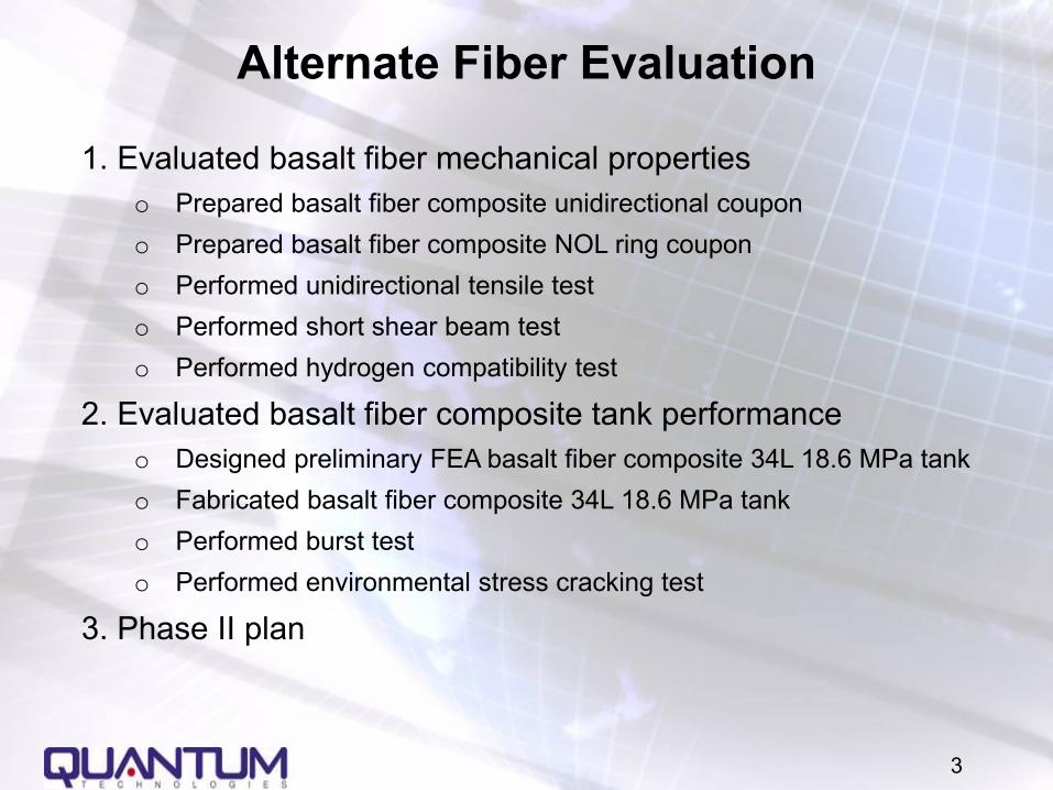
Alternate Fiber Evaluation
1. Evaluated basalt fiber mechanical properties o Prepared basalt fiber composite unidirectional coupon o Prepared basalt fiber composite NOL ring coupon o Performed unidirectional tensile test o Performed short shear beam test o Performed hydrogen compatibility test
2. Evaluated basalt fiber composite tank performance o Designed preliminary FEA basalt fiber composite 34L 18.6 MPa tank o Fabricated basalt fiber composite 34L 18.6 MPa tank o Performed burst test o Performed environmental stress cracking test
3. Phase II plan

0
200
400
600
800
1000
1200
0 10 20 30 40 50 60 70 80 90 100
Tensile Modulus (msi)
Tens
ile S
tren
gth
(ksi
)
Aluminu
Vectran M
Vectran HS
PyronPyron
S-glass
E-Glass
Spectra
Kevlar
Kevlar 49
Arimid
Titanium
Steel
Zylon AS
AS4
T700
T300J
T300
PanexAS4
T400H
AS2
AS8
Zylon HM
T1000
T1000G
T800
M30
IM7
IM6
IM9
Innegra
M40J
M5
IM8
M40
M46M50
M50J
M66JM46J
M60J
M35J
1% Strain to Failure
2% Strain to Failure4% 3% Strain to Failure5%
0.5% Strain to Failure
Fiber Properties Comparison
4
Carbon fiber, Glass, Aramid
Basalt

5
Basalt vs. E Glass • Higher tensile strength (by 15-20%), higher tensile modulus
(by 15-20%) • Extended operation temperature range • Better chemical resistance
Source: Kamenny Vek http://www.basfiber.com/src/filament_winding.pdf

6
Basalt 34L Tank vs. Carbon 34L Tank
EC79: Carbon fiber safety factor (SF) = 2.25, glass fiber SF = 3.5 2.25 < Basalt SF < 3.5

7
Basalt Composite Unidirectional Tensile Test
• Determine basalt/epoxy composite tensile properties
• Compare with carbon fiber • Data for basalt tank design
8
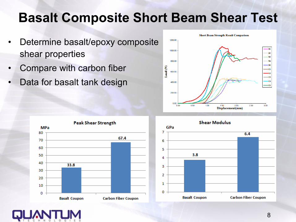
Basalt Composite Short Beam Shear Test
• Determine basalt/epoxy composite shear properties
• Compare with carbon fiber • Data for basalt tank design
9
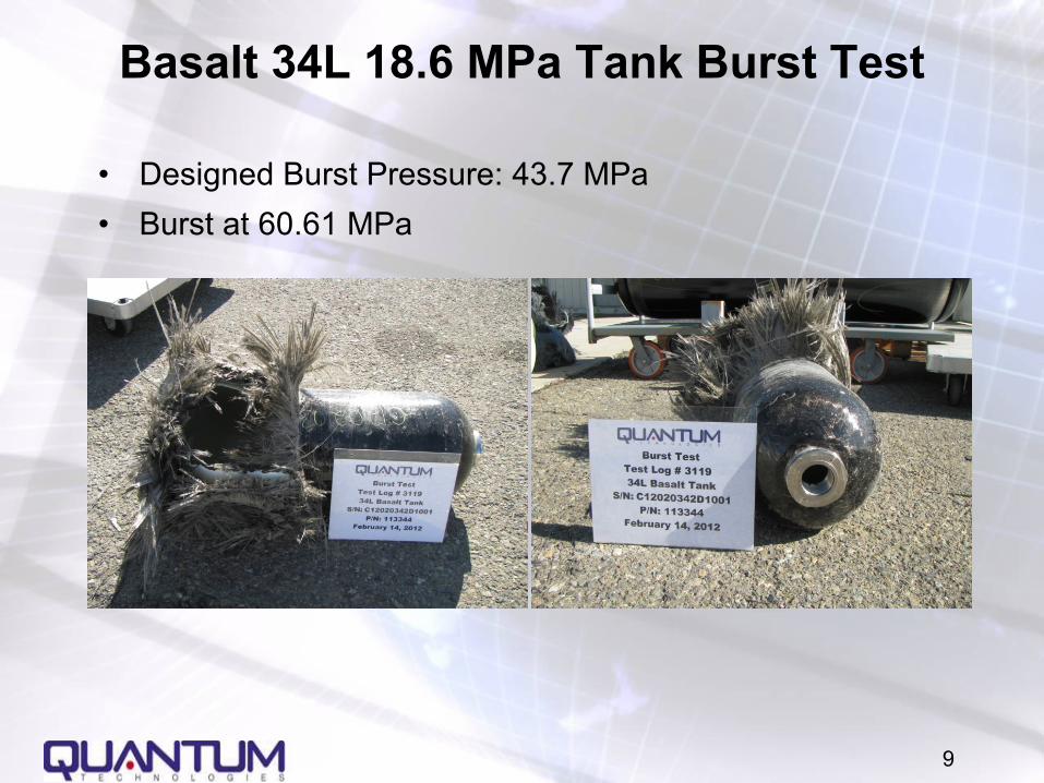
Basalt 34L 18.6 MPa Tank Burst Test
• Designed Burst Pressure: 43.7 MPa • Burst at 60.61 MPa

10
Basalt 34L 18.6 MPa Tank Environmental Stress Cracking Test
• Pendulum impact (30J) followed by chemical exposure • Sulphuric acid – 19% solution by volume in water • Sodium hydroxide – 25% solution by volume in water • Methanol/Gasoline – 5/95% concentration • Ammonium nitrate – 28% solution by volume in water • Windshield washer fluid
• Failed at 2714th cycles • Failed at cylinder section near aft end away from 5 chemical
exposure locations • Chemical nearest failure location
• Windshield washer fluid
• Possible failure reasons: • Improper design safety factor • Damage at AFT End during pendulum impact

11
Phase II Plan
• Determine Proper Design Safety Factor (2.25 to 3.5) • Develop FEA model • Optimize winding parameters • Build 35 MPa (5000 psi) basalt tanks • Perform standard tests
• H2 Gas Cycle Test • Burst Test • Cycle Test • Accelerated Stress Rupture • Extreme Temperature Cycle Test • Composite Flaw Tolerance Test • Drop Test • Penetration Test • Bonfire Test • Chemical Exposure Test

12
Background: Automatic Resin Mixing and Impregnation System - Why It is Important
• Errors may be inadvertently introduced
by operators misreading the scales or using the wrong weight values.
• The current impregnation system retains a large amount of resin which is subject to large viscosity changes.
• The rotating drum used in the current impregnation system may introduce micro-bubbles at high filament velocities.
• The uncontrolled ambient temperature of the production area has a great effect on the mixed resin and its viscosity.
• The tension applied to the fiber is also effected by both the fiber velocity and resin viscosity.
13
Optimization of Filament Winding Processing
1. Evaluate the selected hardware elements 2. Define the required software concepts and methods 3. Fabricate initial machined components for evaluation 4. Control software development

Task 1: Evaluate the Selected Hardware Elements
• Brushless three phase servo motors were selected to drive the various pumps and mixers
• A four quadrant motor operation was specified in the original design
• The amplifier and motor combinations were successfully placed into service and tested using their respective RS485 link
• A test was conducted to demonstrate the ability of the scales accuracy and stability, via serial interface
14

Task 2: Define Required Software Concepts and Methods
• Demonstrated the ability to simultaneously drive and provide real time feedback of a typical mixer using the selected motor amplifier
• Demonstrated the ability to proportionately drive a peristaltic pump using a four quadrant servo control with the real time process variables obtained above
• Demonstrated the ability to incorporate real time operator interface graphics relating the system states and status
• Demonstrated the ability to utilize configuration files which alter the
system’s mixing and impregnation parameters • Demonstrated the ability to simultaneously communicate with each of
the two balance scales via RS232 serial links 15

Task 3: Fabricate Initial Machined Components for Evaluation
• To date, six pump and two mixer assemblies have been fabricated. Illustrated are assembled resin pump and an assembled resin mixer.
16
Figure 1: Aft end of an assembled resin pump. The initial assembly provided fit and print check.
Figure 2: Side view of an assembled resin mixer during fit and print check.
Figure 3: A completed resin pump assembly. The pump assemblies accommodate up to four pump heads which allows up to eight individual pumping tubes.

Task 4: Control Software Development
• A control program utilizing all the functions and methods mentioned above has been completed
• Both resin mixing and impregnation process will be controlled using one graphics interface screen
• Provisions have been incorporated to allow the inclusion of several CSV data acquisition files of real time process data
17
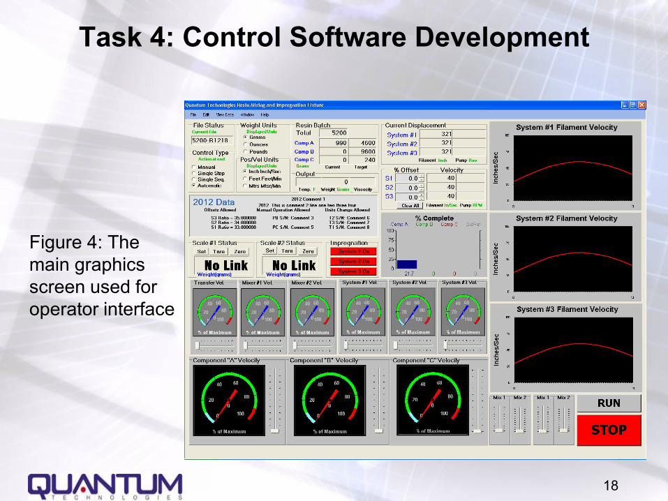
Figure 4: The main graphics screen used for operator interface
18
Task 4: Control Software Development

Recommendations for Completion of the Overall System
Listed below are items and milestones that are currently planned for future project.
1. Fabricate an impregnation assembly capable of impregnating up to eight tows of fiber simultaneously.
2. Using the newly fabricated resin mixing and impregnation system test and debug the control software.
3. Evaluation of the effects of the variance of the individual components as they relate to the overall accuracy of the system.
4. Evaluate the use of a static mixer in lieu of the batch measurement approach.
5. Evaluate composite structure with new mix and impregnation system
19