
Alternative Approach to Modelling of Fluid Distribution in ... · Alternative Approach to Modelling...
6
237 Alternative Approach to Modelling of Fluid Distribution in a Parallel Flow System Vojtěch Turek*, Zdeněk Jegla, Petr Stehlík Institute of Process and Environmental Engineering, Faculty of Mechanical Engineering, Brno University of Technology Technická 2, 616 69 Brno, Czech Republic; [email protected] This paper presents a developed mathematical model of one-dimensional steady single- phase fluid flow in a parallel system of an economizer for high-pressure (10 MPa) water preheating. The unit is a new part of a heat recovery steam generator (HRSG) added for increased steam generation efficiency. Preliminary design of the flow system from the technical-economic point of view is used as a basis for geometry optimization ensuring as low a fluid distribution non-uniformity as possible. The model is utilized for prediction of fluid distribution, outlet temperature and pressure drop on tube side with regard to a known range of operating conditions. It can be used for both incompressible and compressible fluids. Pressure and temperature profiles influenced by inflow or outflow of fluid are constructed for each manifold. Both manifolds are of a constant cross-section and due to the structure of the serpentine coil, a non-uniform heat flux density along the length of individual tubes as well as their different lengths are taken into account. 1. Introduction Tube bundle is an essential part of any parallel flow system present in a tubular heat exchanger. Flow through such a system is influenced by several factors, for example geometry of the system, nature of the flow or heat flux. Generally, the goal is to get fluid distribution that is as close to a uniform one as possible to prevent overheating of the tubes that may cause burn-off, excessive deformations, etc. Analytical investigation of flow through parallel systems was first performed by Bajura and Jones (1976), however, their mathematical model assumed the tubes to be straight and horizontal and did not consider temperature changes in tubes between a splitting and a combining manifold. Datta and Majumdar (1983) proposed a finite difference method extending these results to include the effect of a uniform heat flux. Later on, Ngoma and Godard (2005) presented a model including the effect of a non-uniform heat flux, but inlets and outlets of tubes were considered to be connected to mass points. A hybrid 1D/3D analytical model was proposed by Miao and Xu (2006), though no temperature changes in tubes were considered. Recent investigations include e.g. works by Pustylnik et al. (2010) assuming constant fluid temperature or Ablanque et al. (2010) and Turek et al. (2010) with support for a uniform heat flux. The present model is based on the above mentioned paper by Ngoma and Godard (2005), however, geometry of every tube in a bundle as well as heat flux can be freely
Transcript of Alternative Approach to Modelling of Fluid Distribution in ... · Alternative Approach to Modelling...

237
Alternative Approach to Modelling of Fluid Distribution in a Parallel Flow System
Vojtěch Turek*, Zdeněk Jegla, Petr Stehlík
Institute of Process and Environmental Engineering, Faculty of Mechanical Engineering, Brno University of Technology Technická 2, 616 69 Brno, Czech Republic; [email protected]
This paper presents a developed mathematical model of one-dimensional steady single-phase fluid flow in a parallel system of an economizer for high-pressure (10 MPa) water preheating. The unit is a new part of a heat recovery steam generator (HRSG) added for increased steam generation efficiency. Preliminary design of the flow system from the technical-economic point of view is used as a basis for geometry optimization ensuring as low a fluid distribution non-uniformity as possible. The model is utilized for prediction of fluid distribution, outlet temperature and pressure drop on tube side with regard to a known range of operating conditions. It can be used for both incompressible and compressible fluids. Pressure and temperature profiles influenced by inflow or outflow of fluid are constructed for each manifold. Both manifolds are of a constant cross-section and due to the structure of the serpentine coil, a non-uniform heat flux density along the length of individual tubes as well as their different lengths are taken into account.
1. Introduction Tube bundle is an essential part of any parallel flow system present in a tubular heat exchanger. Flow through such a system is influenced by several factors, for example geometry of the system, nature of the flow or heat flux. Generally, the goal is to get fluid distribution that is as close to a uniform one as possible to prevent overheating of the tubes that may cause burn-off, excessive deformations, etc. Analytical investigation of flow through parallel systems was first performed by Bajura and Jones (1976), however, their mathematical model assumed the tubes to be straight and horizontal and did not consider temperature changes in tubes between a splitting and a combining manifold. Datta and Majumdar (1983) proposed a finite difference method extending these results to include the effect of a uniform heat flux. Later on, Ngoma and Godard (2005) presented a model including the effect of a non-uniform heat flux, but inlets and outlets of tubes were considered to be connected to mass points. A hybrid 1D/3D analytical model was proposed by Miao and Xu (2006), though no temperature changes in tubes were considered. Recent investigations include e.g. works by Pustylnik et al. (2010) assuming constant fluid temperature or Ablanque et al. (2010) and Turek et al. (2010) with support for a uniform heat flux. The present model is based on the above mentioned paper by Ngoma and Godard (2005), however, geometry of every tube in a bundle as well as heat flux can be freely

238
defined and quantities are evaluated along the manifolds instead of considering those to be mass points. Also, due to the previously noted reasons and the possibility of fluid “recirculation” in some region of the flow system, mixing of fluid streams of different temperatures is supported at tube entrances (resp. exits) in both manifolds.
1.1 Description of the Economiser Fig. 1 shows serpentine coil of the economiser. High-pressure water flows as indicated by the arrows. There are 24 tubes in the coil constituting eight “layers” perpendicular to the flow of flue gas. Each tube is of a different length and geometry. Although “Z” flow system arrangement (Fig. 2a) tends to perform better in terms of distribution uniformity, “U” arrangement (Fig. 2b) is used due to limited space available for HRSG elements.
2. Mathematical Model For a one-dimensional steady single-phase flow in a channel having constant cross-section, conservation laws can be written as follows:
( ) (mass),0=∂∂
xvρ (1)
( ) and(momentum)0sinfriction
2
=∂∂
+∂∂
++∂
∂xp
xpg
xv αρρ (2)
Figure 1: Serpentine coil of the economiser.
Figure 2: Flow system arrangements.
239
(energy).sin2
2
SUqgxvhv
x=
⎥⎥⎦
⎤
⎢⎢⎣
⎡⎟⎟⎠
⎞⎜⎜⎝
⎛++
∂∂ αρ (3)
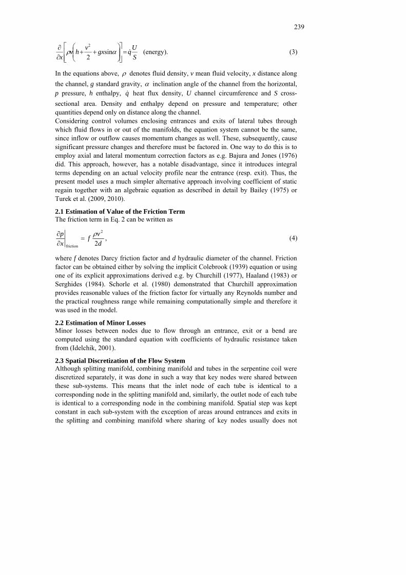
In the equations above, ρ denotes fluid density, v mean fluid velocity, x distance along the channel, g standard gravity, α inclination angle of the channel from the horizontal, p pressure, h enthalpy, q heat flux density, U channel circumference and S cross-sectional area. Density and enthalpy depend on pressure and temperature; other quantities depend only on distance along the channel. Considering control volumes enclosing entrances and exits of lateral tubes through which fluid flows in or out of the manifolds, the equation system cannot be the same, since inflow or outflow causes momentum changes as well. These, subsequently, cause significant pressure changes and therefore must be factored in. One way to do this is to employ axial and lateral momentum correction factors as e.g. Bajura and Jones (1976) did. This approach, however, has a notable disadvantage, since it introduces integral terms depending on an actual velocity profile near the entrance (resp. exit). Thus, the present model uses a much simpler alternative approach involving coefficient of static regain together with an algebraic equation as described in detail by Bailey (1975) or Turek et al. (2009, 2010).
2.1 Estimation of Value of the Friction Term The friction term in Eq. 2 can be written as
,2
2
friction dvf
xp ρ
=∂∂ (4)
where f denotes Darcy friction factor and d hydraulic diameter of the channel. Friction factor can be obtained either by solving the implicit Colebrook (1939) equation or using one of its explicit approximations derived e.g. by Churchill (1977), Haaland (1983) or Serghides (1984). Schorle et al. (1980) demonstrated that Churchill approximation provides reasonable values of the friction factor for virtually any Reynolds number and the practical roughness range while remaining computationally simple and therefore it was used in the model.
2.2 Estimation of Minor Losses Minor losses between nodes due to flow through an entrance, exit or a bend are computed using the standard equation with coefficients of hydraulic resistance taken from (Idelchik, 2001).
2.3 Spatial Discretization of the Flow System Although splitting manifold, combining manifold and tubes in the serpentine coil were discretized separately, it was done in such a way that key nodes were shared between these sub-systems. This means that the inlet node of each tube is identical to a corresponding node in the splitting manifold and, similarly, the outlet node of each tube is identical to a corresponding node in the combining manifold. Spatial step was kept constant in each sub-system with the exception of areas around entrances and exits in the splitting and combining manifold where sharing of key nodes usually does not

240
permit equidistant spacing. Partial derivatives were approximated using the forward finite difference method (Ames 1992, p. 16), i.e.,
( ) ( )x
xpxxpxp
xp ii
Δ−Δ+
=ΔΔ
≈∂∂ (5)
in case of pressure and similarly for other quantities.
3. Results and Discussion The model was implemented in Maplesoft® Maple® and supports three different tube entrance (resp. exit) types in the splitting and combining manifold – sharp, conical and circular bellmouth.
3.1 Comparison with Other Models Only models of single phase adiabatic flow validated with experimental data were found by the authors. In Fig. 3, predictions of the present model are compared to those of Wang and Yu (1989) and Ablanque et al. (2010) (for flow system geometry etc. please refer to either of these two papers). It can be seen that agreement among the models is good, especially between the present model and the one of Ablanque et al. (2010).
3.2 Optimum Diameter of Manifolds in the Studied Economiser Based on known operating conditions, i.e.,
� mass flow rate of water [ ] ,skg 160.6,028.6 1−⋅∈m
Figure 3: Comparison of results yielded by three different models. Manifold inlet and outlet pressures are denoted pin and pout.

241
� heat flux density [ ] ,mW 12920,11780 2035.0035.0 −−− ⋅∈ ii eeq i = 1, …, 8 denotes a specific “layer” of tubes in the coil (obtained during thermal design of the unit),
� inlet temperature [ ] C189,177in °∈T and � inlet pressure MPa,10in =p
preliminary analysis revealed that the best standardized outer diameter of tubes in the serpentine coil is 38.1 mm with tube spacing of 50 mm. Maximum allowed outer diameter of splitting and combining manifold therefore was 350 mm. Also, maximum allowed pressure drop on tube side was 15 kPa. Since parameter ranges were relatively small, standardized tube diameters were preferred and most importantly, character of flow distribution can greatly vary for different manifold diameters due to possible fluid recirculation, a brute force approach to diameter optimization was used. This means that a grid was defined in the search space and distributions were only evaluated for parameter combinations given by this grid. Under such conditions, optimization took roughly 3100 s using a single-core AMD Athlon 64 3200+ CPU. The lowest relative standard deviation from flow uniformity, 3.2%, was obtained for manifolds with inner diameter of 60 mm and sharp tube entrances and exits. In this case the resulting pressure drop on tube side was 14.7 kPa and water outlet temperature 275°C. Dimensionless pressures and mass flow rates for the optimized parallel system are shown in Fig. 4.
Acknowledgement The authors acknowledge financial support of the Ministry of Education, Youth and Sports of the Czech Republic provided within the research plan No. MSM 0021630502�“Waste and Biomass Utilization Focused on Environment Protection and Energy Generation”.
Figure 4: Results for the optimized parallel system. L denotes length of the manifolds; tube No. 1 follows after the inlet section of the splitting manifold (note straight parts of pressure curves).

242
References Ablanque N., Oliet C., Rigola J., Pérez-Segarra C.D. and Oliva A., 2010, Two-phase
flow distribution in multiple parallel tubes, International Journal of Thermal Sciences, 49, 909–921.
Ames W.F., 1992, Numerical methods for partial differential equations, 3rd Ed., Academic Press, New York, NY, United States of America.
Bailey B.J., 1975, Fluid flow in perforated pipes, Journal of Mechanical Engineering Science, 17, 338–347.
Bajura R.A. and Jones E.H., 1976, Flow distribution manifolds, Journal of Fluids Engineering, 98, 654–666.
Churchill S.W., 1977, Friction factor equation spans all fluid regimes, Chemical Engineering, 84, 91–92.
Colebrook C.F., 1939, Turbulent flow in pipes, with particular reference to the transition region between smooth and rough pipe laws, Journal of the Institution of Civil Engineers, 11, 133-156.
Datta A.B. and Majumdar A.K., 1983, A calculation procedure for two phase flow distribution in manifolds with and without heat transfer, International Journal of Heat and Mass Transfer, 26, 1321–1328.
Haaland S.E., 1983, Simple and explicit formulas for the friction factor in turbulent pipe flow, Journal of Fluids Engineering, 105, 89–90.
Idelchik I.E., 2001, Handbook of hydraulic resistance, 3rd Ed., Begell House Publishers, Redding, CT, United States of America.
Miao Z. and Xu T., 2006, Single phase flow characteristics in the headers and connecting tube of parallel tube platen systems, Applied Thermal Engineering, 26, 396–402.
Ngoma G.D. and Godard F., 2005, Flow distribution in an eight level channel system, Applied Thermal Engineering, 25, 831–849.
Pustylnik L., Barnea D. and Taitel Y., 2010, Adiabatic flow distribution of gas and liquid in parallel pipes – Effect of additional restrictions, Chemical Engineering Science, 65, 2552–2557.
Schorle B.J., Churchill S.W. and Shacham M., 1980, Comments on: “An explicit equation for friction factor in pipe”, Industrial and Engineering Chemistry Fundamentals, 19, 228–230.
Serghides T.K., 1984, Estimate friction factor accurately, Chemical Engineering, 91, 63–64.
Turek V., Hájek J, Jegla Z. and Stehlík P., 2010, Optimum design of fluid distribution systems in heat exchangers, Asia-Pacific Journal of Chemical Engineering, in press, DOI: 10.1002/apj.516.
Turek V., Kohoutek J., Jegla Z. and Stehlík P., 2009, Contribution to analytical calculation methods for prediction of uniform fluid flow dividing in tubular distributor, Chemical Engineering Transactions, 18, 809–814.
Wang X.A., Yu P., 1989, Isothermal flow distribution in header systems, International Journal of Solar Energy, 7, 159–169.